WO2011007663A1 - 照射装置 - Google Patents
照射装置 Download PDFInfo
- Publication number
- WO2011007663A1 WO2011007663A1 PCT/JP2010/061002 JP2010061002W WO2011007663A1 WO 2011007663 A1 WO2011007663 A1 WO 2011007663A1 JP 2010061002 W JP2010061002 W JP 2010061002W WO 2011007663 A1 WO2011007663 A1 WO 2011007663A1
- Authority
- WO
- WIPO (PCT)
- Prior art keywords
- electrode
- discharge
- plasma
- excimer
- plasma discharge
- Prior art date
- Legal status (The legal status is an assumption and is not a legal conclusion. Google has not performed a legal analysis and makes no representation as to the accuracy of the status listed.)
- Ceased
Links
Images






Classifications
-
- H—ELECTRICITY
- H01—ELECTRIC ELEMENTS
- H01J—ELECTRIC DISCHARGE TUBES OR DISCHARGE LAMPS
- H01J65/00—Lamps without any electrode inside the vessel; Lamps with at least one main electrode outside the vessel
- H01J65/04—Lamps in which a gas filling is excited to luminesce by an external electromagnetic field or by external corpuscular radiation, e.g. for indicating plasma display panels
- H01J65/042—Lamps in which a gas filling is excited to luminesce by an external electromagnetic field or by external corpuscular radiation, e.g. for indicating plasma display panels by an external electromagnetic field
- H01J65/046—Lamps in which a gas filling is excited to luminesce by an external electromagnetic field or by external corpuscular radiation, e.g. for indicating plasma display panels by an external electromagnetic field the field being produced by using capacitive means around the vessel
-
- H—ELECTRICITY
- H05—ELECTRIC TECHNIQUES NOT OTHERWISE PROVIDED FOR
- H05H—PLASMA TECHNIQUE; PRODUCTION OF ACCELERATED ELECTRICALLY-CHARGED PARTICLES OR OF NEUTRONS; PRODUCTION OR ACCELERATION OF NEUTRAL MOLECULAR OR ATOMIC BEAMS
- H05H1/00—Generating plasma; Handling plasma
- H05H1/24—Generating plasma
- H05H1/2406—Generating plasma using dielectric barrier discharges, i.e. with a dielectric interposed between the electrodes
Definitions
- the present invention relates to an irradiation apparatus that can be suitably used for dry cleaning of a substrate such as a wafer or a glass substrate in a manufacturing process of a semiconductor element or a liquid crystal substrate.
- an organic compound attached to the surface of a substrate such as a silicon wafer or a glass substrate is removed.
- a method for removing such an organic compound water or organic Dry cleaning methods that do not use solvents are widely used.
- a dry cleaning method by irradiating the surface of the object to be processed with vacuum ultraviolet rays having a wavelength of 200 nm or less, the organic compound adhering to the surface of the object to be processed is decomposed and oxidized by active oxygen such as ozone.
- Patent Document 1 Plasma generation by applying a high-frequency electric field while flowing a reactive gas for plasma generation such as nitrogen gas under a pressure near atmospheric pressure.
- Patent Document 2 Plasma cleaning method in which an organic compound adhering to the surface of an object to be processed is decomposed and oxidized by this plasma.
- an optical cleaning method for example, using an irradiation device equipped with an excimer lamp in which xenon is sealed in a discharge vessel, and passing an object to be processed through an irradiation region irradiated with ultraviolet rays from the irradiation device, The object to be processed is cleaned.
- the plasma is instantly changed from glow discharge to arc discharge under atmospheric pressure, and spark discharge is likely to occur. Therefore, an electric field of a short pulse is applied to the electrode, and before the transition from the glow discharge to the arc discharge, the electric field is forcibly switched to prevent the transition from the arc discharge, and the glow discharge is maintained. .
- the conventional irradiation apparatus has the following problems.
- the processing speed of the object to be processed is high, the irradiation time of the vacuum ultraviolet ray to the object to be processed is shortened, so that it is difficult to obtain a high cleaning processing capability. is there.
- the pulse power source for generating a short pulse electric field used in the plasma cleaning method is expensive, there is a problem that the price of the entire apparatus increases.
- a short pulse electric field is applied, complicated control is required for timing with the glass substrate, which is a processed object, and a steep electric field is generated, resulting in noise problems.
- an object of the present invention is to provide an irradiation apparatus that can obtain a high cleaning ability and can reliably remove an organic compound having a chemical bond having a high binding energy.
- Another object of the present invention is to provide a new atmospheric pressure plasma generator capable of preventing the transition from glow discharge to arc discharge and solving various problems of using a pulse power supply. is there.
- a first invention of the present application includes an excimer lamp having a discharge vessel and a pair of electrodes, and a plasma discharge electrode disposed so as to face one electrode of the excimer lamp via a dielectric, in the excimer lamp.
- a plasma generation circuit is formed through the one electrode and the plasma discharge electrode, and an excimer discharge is generated in the discharge vessel by a high-frequency electric field applied between a pair of electrodes in the excimer lamp, A high-frequency electric field applied between the one electrode and the plasma discharge electrode in the excimer lamp in a state where a reactive gas for plasma generation is passed between the excimer lamp and the plasma discharge electrode.
- a second invention of the present application is the irradiation apparatus according to the first invention, wherein an electric field concentration convex portion is formed on the surface of the dielectric.
- a third invention of the present application is the irradiation apparatus according to the first or second invention, wherein an electric field concentration convex portion is formed on a surface of the plasma discharge electrode.
- a fourth invention of the present application is the invention according to any one of the first to third inventions, further comprising a lamp house in which the excimer lamp is disposed, and the plasma discharge electrode is integrated with the lamp house. An irradiation apparatus is provided.
- a fifth invention of the present application is the irradiation apparatus according to any one of the first to fourth inventions, wherein the plasma discharge is generated by a high frequency power source for excimer discharge.
- an inert gas is enclosed in a reactive gas layer in which a reactive gas is flowing under atmospheric pressure in a space between a pair of electrodes to which an alternating electric field is supplied and a discharge vessel.
- the inert gas layer is arranged so as to be continuous in parallel with the electrodes, and the discharge generated between the electrodes is divided into a plasma discharge in the reactive gas layer and an excimer discharge in the inert gas layer. It is an irradiation device characterized by generating via.
- one electrode is attached to the discharge vessel, the other electrode is attached to a lamp house in which the discharge vessel is disposed, and the lamp house and the discharge vessel
- the irradiation apparatus is characterized in that a reactive gas layer is formed therebetween.
- the one electrode has one side electrode extending on a side surface of the discharge vessel, and has the same potential as the other electrode at a position facing the one side electrode.
- the irradiation apparatus is characterized in that the other side electrode to which power is supplied is attached, and a dielectric is provided between the one side electrode and the other side electrode.
- a dielectric having an area larger than that of the one electrode is disposed between the discharge container and the one electrode on a surface of the dielectric facing the object to be processed. It is an irradiation apparatus characterized by being attached.
- the tenth invention of the present application includes an internal electrode arranged inside a discharge vessel in which an inert gas layer filled with an inert gas is formed, and a reactive gas flowing outside the discharge vessel under atmospheric pressure. An AC electric field is supplied between the external electrode arranged with the reactive gas layer interposed therebetween, and the discharge generated between the external electrode and the internal electrode is inactive with the plasma discharge in the reactive gas layer. It is an irradiation device that is generated through excimer discharge in a gas layer.
- An eleventh invention of the present application is the irradiation device according to the tenth invention, wherein a high voltage is supplied to the internal electrode.
- both the cleaning process by the ultraviolet rays from the excimer lamp and the cleaning process by the plasma generated between the excimer lamp and the plasma discharge electrode are performed on the object to be processed. Therefore, it is possible to obtain a high cleaning capability for the object to be processed, and even for organic compounds having a chemical bond with a high binding energy that is difficult to remove only by the cleaning treatment with ultraviolet rays, the plasma cleaning treatment is performed. Therefore, it can be reliably removed.
- the reactive gas layer is generated by causing the discharge generated by the pair of electrodes to be generated through the reactive gas layer and the inert gas layer.
- the transition of the plasma discharge to the arc discharge can be prevented and the plasma discharge can be maintained stably.
- the object to be processed can be subjected to both the cleaning process using ultraviolet light from the excimer lamp and the cleaning process using plasma generated between the excimer lamp and the electrode, a high cleaning process can be performed on the object to be processed.
- the irradiation apparatus since the reactive gas layer is formed between the lamp house and the discharge vessel, the side electrode extending on the side surface of the discharge vessel and the electrode are the same. Plasma discharge is generated between the other side electrode to which electric power is supplied so as to have a potential.
- the object W can be irradiated with a gas containing more plasma, and the organic compound attached to the surface of the object W is more efficiently decomposed and oxidized.
- the dielectric having a larger area than the electrode is disposed between the discharge container and the electrode is attached to the surface of the dielectric facing the object to be processed. It is possible to prevent the electrodes from running along the side surfaces of the discharge vessel of the excimer lamp and causing an arc short circuit along the creeping surface.
- the discharge of the reactive gas layer is caused by causing the discharge generated at the pair of electrodes to be generated through the reactive gas layer and the inert gas layer. Since it can be stopped without sustaining, even if a sinusoidal AC voltage is supplied, the transition of the plasma discharge to the arc discharge can be prevented, and the plasma discharge can be maintained stably.
- the object to be processed can be subjected to both the cleaning process using ultraviolet light from the excimer lamp and the cleaning process using plasma generated between the excimer lamp and the electrode, a high cleaning process can be performed on the object to be processed.
- the inner electrode since the inner electrode is in a closed space inside the discharge vessel, insulation can be easily achieved by setting the inner electrode to the high voltage side. .
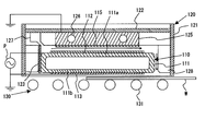
- FIG. 1 is a cross-sectional view illustrating a configuration of an irradiation apparatus according to the present embodiment.
- this irradiation apparatus is used for, for example, dry-cleaning the surface of an object to be processed such as a liquid crystal substrate, and includes an excimer lamp 110 that emits vacuum ultraviolet rays having a wavelength of 200 nm or less.
- the excimer lamp 110 is disposed in a rectangular box-shaped lamp house 120 having an open bottom surface.
- a transport mechanism 130 that transports and moves the workpiece W in the horizontal direction is provided below the excimer lamp 110.
- the transport mechanism 130 is configured such that a plurality of transport rollers 131 are arranged along the transport direction of the object to be processed.
- the excimer lamp 110 has a rectangular box-shaped discharge vessel 111 in which an excimer gas is hermetically sealed.
- One film-like electrode 112 is provided on the outer surface (upper surface in FIG. 1) of the upper side portion 111a in the discharge vessel 111, and the outer surface (lower surface in FIG. 1) of the lower side portion 111b in the discharge vessel 111 is The other net-like electrode 113 is provided, and each of the one electrode 112 and the other electrode 113 is connected to the high-frequency power source P.
- one electrode 112 is a high-voltage side electrode
- the other electrode 113 is a ground-side electrode.
- a material that can transmit vacuum ultraviolet rays well specifically, silica glass such as synthetic quartz glass, sapphire glass, or the like can be used.
- a material constituting one electrode 112 and the other electrode 113 a metal material such as aluminum, nickel, or gold can be used.
- the one electrode 112 and the other electrode 113 can be formed by screen-printing a conductive paste containing the metal material or by vacuum-depositing the metal material.
- the excimer gas enclosed in the discharge vessel 111 can generate an excimer that emits vacuum ultraviolet rays, specifically, a rare gas such as xenon, argon, krypton, or a rare gas and bromine, chlorine. Further, a mixed gas in which a halogen gas such as iodine or fluorine is mixed can be used.
- the sealing pressure of the excimer gas is, for example, 10 to 80 kPa.
- a plasma discharge dielectric film 115 is formed on one electrode 112 of the excimer lamp 110 so as to cover the one electrode 112.
- a dielectric material such as alumina (Al 2 O 3 ), silica (SiO 2 ), or the like can be used.
- the plasma discharge dielectric film 115 can be formed by spraying or depositing the dielectric material on the surface of one of the electrodes 112.
- each of the upper side portion 111a and the lower side portion 111b in the discharge vessel 111 is preferably 0.5 to 5 mm. Further, the distance (discharge gap) between the upper side portion 111a and the lower side portion 111b in the discharge vessel 111 in the discharge vessel 111 is preferably 0.05 to 5 mm.
- the thickness of the plasma discharge dielectric film 115 is preferably 0.01 to 4 mm. When this thickness is too small, arc discharge is likely to occur between the plasma discharge dielectric film 115 and the plasma discharge electrode 125. On the other hand, when this thickness is excessive, it is difficult to generate plasma discharge between the plasma discharge dielectric film 115 and the plasma discharge electrode 125.
- the lamp house 120 includes a rectangular cylindrical side wall member 121 that forms a side wall, and an upper plate 122 that closes an opening at the top of the side wall member 121.
- a rectangular parallelepiped plasma discharge electrode 125 made of aluminum is provided integrally with the upper plate 122.
- the plasma discharge electrode 125 is provided with a plurality of cooling water pipes 126 extending in the horizontal direction (direction perpendicular to the paper surface in FIG. 1).
- the excimer lamp 110 is fixedly disposed in the lamp house 120 by a fixing plate 123 so that the plasma discharge electrode 125 faces the one electrode 112 with the plasma discharge dielectric film 115 interposed therebetween, and the plasma discharge electrode 125.
- a plasma generation circuit is formed through one electrode 112 and the plasma discharge electrode 125 in the excimer lamp 110.
- the plasma discharge is generated by the high frequency power supply P for excimer discharge in the excimer lamp 110, that is, the excimer discharge and the plasma discharge are both performed by the common high frequency power supply P.
- 127 and a guide member 128 for guiding the gas flowing between the one electrode 112 and the plasma discharge electrode 125 downward is provided at a side position of the excimer lamp 110.
- the separation distance between the plasma discharge dielectric film 115 and the plasma discharge electrode 125 is preferably 1 to 10 mm. If the separation distance is too small, it may be difficult to flow the plasma generating reactive gas between the plasma discharge dielectric film 115 and the plasma discharge electrode 125. On the other hand, if the separation distance is excessive, it may be difficult to generate plasma discharge between the one electrode 112 and the plasma discharge electrode 125 in the excimer lamp 110.
- a reactive gas for generating plasma is supplied from the manifold 127 between the dielectric film 115 for plasma discharge and the electrode for plasma discharge 125 under atmospheric pressure or a pressure in the vicinity thereof and flowed through.
- the reactive gas for generating plasma is mainly composed of nitrogen gas (N 2 ), argon gas (Ar), carbon dioxide gas (CO 2 ), helium gas (He), etc., and contains oxygen gas in an amount of 1 to 2% by volume. Is preferably used.
- the flow rate per unit length of the reactive gas for generating plasma is preferably 0.5 to 4 m 3 / s per meter.
- a high-frequency electric field is applied between the one electrode 112 and the other electrode 113 in the excimer lamp 110 by a high-frequency power source P, with one electrode 112 serving as a high-voltage side electrode and the other electrode 113 serving as a ground-side electrode.
- Excimer discharge is generated in the discharge vessel 111 of the excimer lamp 110 by the high-frequency electric field, and excimer molecules derived from the excimer gas are formed by this excimer discharge, and thereby, vacuum ultraviolet rays are emitted.
- one electrode 112 and the plasma discharge electrode 125 in the excimer lamp 110 one electrode 112 serves as a high-pressure side electrode, and the plasma discharge electrode 125 serves as a ground-side electrode.
- a high-frequency electric field is applied by the high-frequency power source P, and this high-frequency electric field generates a plasma discharge (glow discharge) between the plasma discharge dielectric film 115 and the plasma discharge electrode 125, and this plasma discharge causes a plasma discharge.
- the generating reactive gas is ionized or excited to generate plasma.
- the power supplied from the high frequency power source P is preferably a high frequency having a frequency of 10 to 100 kHz, and the voltage is preferably a high voltage of 1 kVrms to several tens of kVrms.
- the discharge state between the plasma discharge dielectric film 115 and the plasma discharge electrode 125 does not shift from glow discharge to arc discharge, and plasma discharge can be maintained stably.
- the excimer discharge and plasma discharge start voltages are determined by the pressure in the discharge space, the size of the discharge gap, the type of gas, etc., but the plasma discharge start voltage is high and the plasma discharge is excimer discharge. More preferably, it is set so as to occur with a delay of several microseconds, for example. When these conditions are satisfied, photoelectrons are generated by radiating vacuum ultraviolet rays by excimer discharge, so that plasma discharge can be generated easily and stably.
- the surface of the workpiece W that is moved in the horizontal direction by the transport mechanism 130 is irradiated with vacuum ultraviolet rays emitted from the excimer lamp 110, and active oxygen such as ozone generated by the vacuum ultraviolet rays is irradiated.
- active oxygen such as ozone generated by the vacuum ultraviolet rays
- the organic compound attached to the surface of the object to be processed W is decomposed and oxidized.
- the plasma-containing gas generated between the plasma discharge dielectric film 115 and the plasma discharge electrode 125 is guided downward by the side surface of the excimer lamp 110 and the guide member 128 and moved in the horizontal direction by the transport mechanism 130.
- the organic compound attached to the surface of the object to be processed W is decomposed and oxidized.
- chemical bonds such as C—C bonds, C—H bonds, and C ⁇ C bonds in organic compounds have a relatively low bond energy, and can be cut by the energy of vacuum ultraviolet rays. It can be oxidized and gasified by reacting with active oxygen generated by ultraviolet rays.
- a chemical bond such as a C ⁇ O bond has a high bond energy and cannot be cut by the energy of vacuum ultraviolet rays, but can be oxidized and gasified by oxygen radicals generated by plasma discharge. In this way, the object to be processed W is subjected to the cleaning process using vacuum ultraviolet rays and the cleaning process using plasma.
- the object to be processed W is cleaned with vacuum ultraviolet light from the excimer lamp 110 and cleaned with plasma generated between the one electrode 112 and the plasma discharge electrode 125 in the excimer lamp 110. Since both processes can be performed, a high cleaning processing capability is obtained for the workpiece W. In addition, an organic compound having a chemical bond having a high binding energy, which is difficult to remove only by a cleaning process using vacuum ultraviolet rays, can be reliably removed because it is oxidized and gasified by the cleaning process using plasma.
- the irradiation apparatus according to the present embodiment is not limited to the configuration shown in FIG. 1, and various modifications can be made as described in the following (1) to (6).
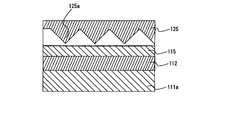
- a large number of electric field concentration convex portions 115 a can be formed on the surface of the plasma discharge dielectric film 115.
- a large number of electric field concentration convex portions 125 a can be formed on the surface of the plasma discharge electrode 125.
- the electric field concentration convex portion 115a and the plasma discharge electrode 125 of the plasma discharge dielectric film 115 or the electric field concentration convexity of the plasma discharge dielectric film 115 and the plasma discharge electrode 125 are formed.
- the part 125a may be separated from or in contact with the part 125a, and the separation distance is preferably 2 mm or less.
- the projecting heights of the electric field concentration convex portion 115a of the plasma discharge dielectric film 115 or the electric field concentration convex portion 125a of the plasma discharge electrode 125 are preferably 3 to 10 mm, respectively. According to such a configuration, the electric field concentration between the convex portion 115a for concentrating the electric field of the dielectric film 115 for plasma discharge and the plasma discharge electrode 125, or for concentrating the electric field between the dielectric film 115 for plasma discharge and the plasma discharge electrode 125.
- a high frequency electric field is concentrated between the convex portion 125a and a discharge state in which creeping discharge and equal electric field type discharge are combined is obtained, so that the starting voltage for plasma discharge can be lowered, Even when the distance between the plasma discharge dielectric film 115 and the plasma discharge electrode 125 changes due to thermal expansion of the discharge vessel 111 during operation, the plasma discharge can be stably maintained.
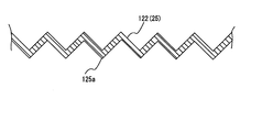
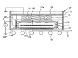
- the upper plate 122 in the lamp house 120 can be used as the plasma discharge electrode 125 as shown in FIG.
- the electric field concentration convex portion 125a can be formed by forming the upper plate 122 in a bellows shape.
- the plasma discharge dielectric film 115 may be formed on the surface of the plasma discharge electrode 125.
- one electrode 112 in the excimer lamp 110 may be disposed inside the discharge vessel 111.
- the upper portion 111a of the discharge vessel 111 in the excimer lamp 110 can be used as a dielectric for plasma discharge.
- an excimer discharge is generated between the one electrode 112 and the lower portion 111 b of the discharge vessel 111, and the excimer is generated between the one electrode 112 and the upper portion 111 a of the discharge vessel 111. Discharge occurs. Therefore, both the excimer discharge and the plasma discharge are generated between the one electrode 112 and the plasma discharge electrode 125, so that the discharge state can be easily controlled.
- the irradiation apparatus shown in FIG. 1 is configured such that both excimer discharge and plasma discharge are performed by a common high-frequency power source P.
- the high-frequency power source for plasma discharge is used for excimer discharge in the excimer lamp 110.
- a configuration provided separately from the high-frequency power source for the above-described configuration may be used.
- one electrode 112 in the excimer lamp 110 is a high-voltage side electrode and the plasma discharge electrode 125 is a ground-side electrode, but the plasma discharge electrode 125 is a high-voltage side electrode.
- the structure made into the electrode may be sufficient.
- FIG. 8 is a cross-sectional view illustrating a configuration of an irradiation apparatus according to the second embodiment.
- an excimer lamp 210 is disposed inside the lamp house 220, and a transport mechanism 230 for transporting and moving the workpiece W in the horizontal direction is provided below the excimer lamp 210.
- the lamp house 220 is disposed so that the side wall members 221a and 221b forming the side walls face each other, and a top plate 222 is formed so as to close the opening at the top of the side wall members 221a and 221b.
- the lamp house 220 is divided into side wall members 221a and 221b and a top plate 222, so that the excimer lamp 210 disposed inside the lamp house 220 can be replaced by making the top plate 222 openable.
- the transport mechanism 230 is configured such that a plurality of transport rollers 231 are arranged along the transport direction of the workpiece W.
- a rectangular parallelepiped plasma discharge electrode 225 made of, for example, aluminum is provided on the inner surface of the top plate 222 of the lamp house 220.
- a plurality of cooling water pipes 226 extending horizontally along the longitudinal direction of the excimer lamp 210 are provided inside the plasma discharge electrode 225.
- a manifold 227 for supplying a reactive gas between the excimer lamp 210 and the plasma discharge electrode 225 is provided between the one side wall member 221 a and the plasma discharge electrode 225.
- the reactive gas is mainly composed of nitrogen gas (N 2 ), argon gas (Ar), carbon dioxide gas (CO 2 ), helium gas (He), etc., and contains 1 to 2% by volume of oxygen gas. Is preferably used.
- the flow rate per unit length is set to 0.5 to 4 m 3 / s per meter.
- the reactive gas flows from the manifold 227 between the plasma discharge electrode 225 and the excimer lamp 210 under the atmospheric pressure or a pressure in the vicinity thereof, and is to be processed below the excimer lamp 210 through the gap between the other side wall member 221b.
- the fixing plate 223 is disposed so as to contact the side surface of the excimer lamp 210 so that the reactive gas does not flow out along the one side wall member 221a.
- a guide member 228 is disposed between the other side wall member 221b and a side surface of the excimer lamp 210 with a gap through which reactive gas flows.
- the excimer lamp 210 contains a rare gas or a rare gas and a halogen gas in a hollow rectangular discharge vessel 211 having a rectangular cross section that transmits vacuum ultraviolet rays such as synthetic silica glass and sapphire.
- An inert gas composed of a mixed gas mixture is hermetically sealed, for example, at 10 to 80 kPa.
- a net-like excimer discharge electrode 213 is provided on the outer surface of the lower surface 211b of the discharge vessel 211 facing the object to be processed W.
- the excimer discharge electrode 213 is made of a metal material such as aluminum, nickel, or gold, and is formed by screen-printing a conductive paste containing these metal materials or vacuum-depositing the metal materials.
- the plasma discharge electrode 225 and the excimer discharge electrode 213 are connected to a high-frequency power source P that supplies a sinusoidal AC voltage.
- the power supplied from the high-frequency power source P has, for example, a frequency of 10 to 100 kHz and a voltage of 1 kVrms to several tens of kVrms.
- Excimer discharge is generated in the inert gas layer 214 to form excimer molecules, and vacuum ultraviolet rays are emitted.
- a plasma discharge is generated by the high frequency electric field applied to the reactive gas layer 224, and the reactive gas 224 is ionized or excited to generate plasma.
- the surface of the workpiece W that is moved in the horizontal direction by the transport mechanism 230 is irradiated with the vacuum ultraviolet rays emitted from the excimer lamp 210, and active oxygen such as ozone generated by the vacuum ultraviolet rays is irradiated on the workpiece W.
- active oxygen such as ozone generated by the vacuum ultraviolet rays is irradiated on the workpiece W.
- a gas containing plasma is guided downward by the side surface of the excimer lamp 210 and the guide member 228 and comes into contact with the surface of the object to be processed W, whereby the organic compound attached to the surface of the object to be processed W is decomposed and oxidized. Is done. Since the object to be processed W can be subjected to both the cleaning process using vacuum ultraviolet light from the excimer lamp 210 and the cleaning process using plasma, a high cleaning process capability can be obtained for the object to be processed W.
- the starting voltage of excimer discharge and plasma discharge is determined by the pressure in the discharge space, the size of the discharge gap, the type of gas, etc., but the starting voltage of plasma discharge is higher than the starting voltage of excimer discharge, and the plasma discharge is excimer. For example, it is preferably set so as to be delayed by several microseconds from the discharge.
- the size of the discharge gap between the reactive gas layer 224 and the inert gas layer 214 and the gas pressure of the inert gas layer 214 are set so that these conditions are satisfied.
- the distance between the excimer lamp 210 and the plasma discharge electrode 225 which is the size of the discharge gap of the reactive gas layer 224, is set to 1 to 10 mm, and the upper surface 211a of the discharge vessel 211 that becomes the discharge gap of the inert gas layer 214 The distance from the lower surface 211b is set to 0.05 to 5 mm.
- the case where a sinusoidal AC voltage is supplied using the plasma discharge electrode 225 as the high voltage generation side will be described.
- the high voltage applied to the excimer discharge electrode 213 charges the lower surface 211b of the excimer lamp 210, and when the accumulated charge reaches the excimer discharge start voltage, the excimer discharge occurs in the inert gas layer 214. appear. Furthermore, when the excimer discharge in the inert gas layer 214 charges the upper surface 211a of the excimer lamp 210 and reaches the discharge start voltage of the plasma discharge, a plasma discharge is generated in the reactive gas layer 224.
- the voltage between the upper surface 211a and the lower surface 211b of the excimer lamp 210 decreases due to the excimer discharge, and thus the discharge is stopped without being maintained. Furthermore, by stopping the excimer discharge, the current to the reactive gas layer 224 is limited and the plasma discharge is also stopped.
- the applied high voltage is further increased, the above state is repeatedly generated and discharged until the maximum voltage is reached. Since the discharge of the reactive gas layer 224 can be stopped without sustaining, the transition to the arc discharge can be prevented. When the polarity of the plasma discharge electrode 225 is reversed, the discharge is generated again.
- the reactive gas layer 224 and the inert gas layer 214 By arranging the reactive gas layer 224 and the inert gas layer 214 in line with the electrodes 213 and 225 in a space between the plasma discharge electrode 225 and the excimer discharge electrode 213, a pair of electrodes The discharge generated at 225 and 213 is caused to occur through the reactive gas layer 224 and the inert gas layer 214.
- the discharge of the reactive gas layer 224 can be stopped without being sustained, so that even if a sinusoidal AC voltage is supplied, the transition of the plasma discharge to the arc discharge can be prevented, and the plasma discharge can be stabilized. Can be maintained.
- FIG. 9 is a cross-sectional view showing a configuration of an irradiation apparatus in which the installation position of the plasma discharge electrode 225 is changed in the irradiation apparatus according to the second embodiment.
- FIG. 8 when the plasma discharge electrode 225 is disposed inside the lamp house 220 and a high voltage is supplied to the plasma discharge electrode 225, it is difficult to insulate the lamp house 220 and other members. There is.
- a plasma discharge electrode 225 is arranged separately from the top plate 222 of the lamp house 220 so as to be suspended from the top plate 222. With this configuration, the plasma discharge electrode 225 can be easily insulated.
- FIG. 10 is a cross-sectional view showing a configuration of an irradiation apparatus in which an excimer discharge electrode 213 is installed via a dielectric 215 in the irradiation apparatus according to the second embodiment.
- the excimer discharge electrode 213 is not directly attached to the discharge vessel 211, but a dielectric 215 having a larger area than the excimer discharge electrode 213 is disposed between the discharge vessel 211 and the dielectric
- An excimer discharge electrode 213 is attached to a surface of the substrate 215 that faces the workpiece W. In this way, by using the dielectric 215, the excimer discharge electrode 213 and the plasma discharge electrode 225 can prevent discharge from running on the side surface of the discharge vessel 211 of the excimer lamp 210 and arc short-circuiting along the surface. .
- the discharge generated between the plasma discharge electrode 225 and the excimer discharge electrode 213 is caused between the dielectric and the excimer lamp 210.
- An inert gas layer 214 in which excimer discharge is generated is present between the reactive gas layers 224 in which plasma discharge is generated and plasma discharge is generated.
- FIG. 11 is a cross-sectional view showing the configuration of the irradiation apparatus according to this embodiment.
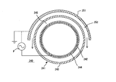
- the excimer lamp 240 includes a discharge vessel 241 having a double tube structure in which an outer tube 243 and an inner tube 242 are coaxially arranged, and is a space surrounded by the outer tube 243 and the inner tube 242. An inert gas is sealed in the structure.
- a bowl-shaped reflecting mirror 251 made of aluminum is disposed above the excimer lamp 240. The reactive gas flows between the excimer lamp 240 and the reflecting mirror 251 under atmospheric pressure, and the leaked gas flows toward the object to be processed.
- An inner electrode 244 made of a cylindrical metal member is formed on the inner peripheral surface of the inner tube 242 of the excimer lamp 240, and a high frequency power supply P that supplies a sine wave AC voltage is connected with the reflecting mirror 251 as the other electrode.
- a high frequency power supply P that supplies a sine wave AC voltage is connected with the reflecting mirror 251 as the other electrode. Since the inner electrode 244 is in a closed space inside the inner tube 242, insulation can be easily achieved by setting the inner electrode 244 to the high voltage side and the reflecting mirror 251 to the low voltage side.
- an inert gas layer 245 in which an inert gas is sealed inside the discharge vessel 241 and a reactivity in which a reactive gas flows under atmospheric pressure. It arrange
- the discharge of the reactive gas layer 252 can be stopped without sustaining, so that the transition of the plasma discharge to the arc discharge can be prevented even when the sine wave AC voltage is supplied, and the plasma discharge is stabilized. Can be maintained.
- the object to be processed can be subjected to both the cleaning process using vacuum ultraviolet light from the excimer lamp 240 and the cleaning process using plasma, a high cleaning processing capability can be obtained for the object to be processed.
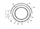
- FIG. 12 is a cross-sectional view showing a configuration of an irradiation apparatus in which an external electrode 246 is attached to the lower half of the discharge vessel 241 in the irradiation apparatus according to the third embodiment.
- an external electrode 246 is attached to the lower half of the outer tube 243 of the discharge vessel 241 of the excimer lamp 240, and the external electrode 246 is grounded.
- a high voltage is applied to the inert gas sealed in the lower half of the discharge vessel 241 between the inner electrode 244 and the outer electrode 246, and excimer discharge occurs.
- the external electrode 246 is attached to the lower half of the outer tube 243.
- the lower half side of the inner electrode 244 can also contribute to the discharge, and the cleaning ability of the object to be processed can be enhanced.
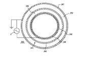
- FIG. 13 is a cross-sectional view showing a configuration of an irradiation apparatus according to the third embodiment in which a mesh electrode 247 that covers the entire circumference of the discharge vessel 241 is attached instead of the reflecting mirror 251.
- a mesh electrode 247 is attached so as to cover the entire periphery of the discharge vessel 241 via a reactive gas layer 252.
- a mesh electrode 247 is formed so as to sandwich the entire circumference of the inner electrode 244 via an inert gas layer 245 and a reactive gas layer 252.
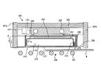
- FIG. 14 is a cross-sectional view showing the configuration of the irradiation apparatus according to the present embodiment.
- a side electrode 229 is attached to a guide member 228 that guides a reactive gas to flow toward a workpiece W below the excimer lamp 210, and an electrode 225 for plasma discharge is provided. Electric power is supplied so as to have the same potential as that.
- a dielectric 219 made of a dielectric material such as alumina (Al 2 O 3 ) or silica (SiO 2 ) is formed on the surface of the guide member 228.
- the excimer discharge electrode 213 formed on the lower surface 211 b of the discharge vessel 211 is formed to extend to the side surface 212 facing the guide member 228.
- the plasma is generated between the excimer discharge electrode 213 extending to the side surface 212 and the side electrode 229 facing through the dielectric 219. Discharge occurs.
- the object W can be irradiated with a gas containing more plasma, and the organic compound attached to the surface of the object to be processed W It is decomposed and oxidized more efficiently.
- FIG. 15 is a cross-sectional view showing the configuration of the irradiation apparatus according to the present embodiment.
- this irradiation apparatus includes an excimer lamp 310 disposed inside a lamp house 320, and a transport mechanism 330 that transports and moves the workpiece W in the horizontal direction below the excimer lamp 310. It has been.
- the lamp house 320 is arranged so that the side wall members 321a and 321b forming the side walls face each other, and a top plate 322 is formed so as to close the opening at the top of the side wall members 321a and 321b.
- the lamp house 320 is configured by dividing it into side wall members 321a and 321b and a top plate 322, so that the excimer lamp 310 disposed inside the lamp house 320 can be exchanged by making the top plate 322 openable.
- the transport mechanism 330 is configured such that a plurality of transport rollers 331 are arranged along the transport direction of the workpiece W.
- a rectangular parallelepiped outer electrode 325 made of, for example, aluminum is provided on the inner surface of the top plate 322 of the lamp house 320.
- a plurality of cooling water pipes 326 extending horizontally along the longitudinal direction of the excimer lamp 310 are provided inside the outer electrode 325.
- a manifold 327 is provided between one side wall member 321 a and the outer electrode 325, and a reactive gas is supplied between the excimer lamp 310 and the outer electrode 325.
- the reactive gas is mainly composed of nitrogen gas (N 2 ), argon gas (Ar), carbon dioxide gas (CO 2 ), helium gas (He), etc., and contains 1 to 2% by volume of oxygen gas. Is preferably used.
- the flow rate per unit length is set to 0.5 to 4 m 3 / s per meter.
- the reactive gas flows between the outer electrode 325 and the excimer lamp 310 from the manifold 327 under the atmospheric pressure or a pressure in the vicinity thereof, and the workpiece W below the excimer lamp 310 is formed through a gap between the other side wall member 321b.
- the generated plasma is irradiated to the workpiece W by flowing toward the surface.
- the fixing plate 323 is arranged so as to contact the side surface of the excimer lamp 310 so that the reactive gas does not flow out along the one side wall member 321a.
- a guide member 328 is disposed between the other side wall member 321b and a gap through which reactive gas flows between the side surface of the excimer lamp 310 and the side wall member 321b.
- the excimer lamp 310 contains a rare gas or a rare gas and a halogen gas in a hollow rectangular discharge vessel 311 having a rectangular cross-section that can transmit vacuum ultraviolet rays such as synthetic silica glass and sapphire.
- An inert gas composed of a mixed gas mixture is hermetically sealed, for example, at 10 to 80 kPa.
- An inner electrode 313 is provided inside the discharge vessel 311.
- the inner electrode 313 is made of a metal material such as aluminum, nickel, or gold, and is formed by supporting the inside of the discharge vessel 311 or screen printing a conductive paste on the inner surface of the discharge vessel 311.
- the outer electrode 325 and the inner electrode 313 are connected to a high frequency power source P that supplies a sinusoidal AC voltage.
- the power supplied from the high-frequency power source P has, for example, a frequency of 10 to 100 kHz and a voltage of 1 kVrms to several tens of kVrms.
- an inert gas layer 314 in which an inert gas is sealed inside the discharge vessel 311 and a reactive gas layer 324 in which the reactive gas flows under atmospheric pressure. It is arranged so as to be sandwiched continuously. For this reason, the discharge between the outer electrode 325 and the inner electrode 313 passes through the plasma discharge and the excimer discharge via the upper surface 311a of the excimer lamp 310.
- Excimer discharge is generated in the inert gas layer 314 sandwiched between the inner electrode 313 and the upper surface 311a of the discharge vessel 311 to form excimer molecules, and vacuum ultraviolet rays are emitted.
- a plasma discharge is generated by a high-frequency electric field applied to the reactive gas layer 324, and the reactive gas 324 is ionized or excited to generate plasma.
- the surface of the workpiece W that is moved in the horizontal direction by the transport mechanism 330 is irradiated with vacuum ultraviolet rays emitted from the excimer lamp 310, and active oxygen such as ozone generated by the vacuum ultraviolet rays is irradiated on the workpiece W.
- the organic compound attached to the surface of the workpiece W is decomposed and oxidized. Further, the gas containing plasma is guided downward by the side surface of the excimer lamp 310 and the guide member 328 and comes into contact with the surface of the object to be processed W, whereby the organic compound attached to the surface of the object to be processed W is decomposed and oxidized. Is done. Since both the cleaning process using vacuum ultraviolet rays from the excimer lamp 310 and the cleaning process using plasma can be performed on the target object W, a high cleaning processing capability can be obtained for the target object W.
- the excimer discharge and plasma discharge start voltages are determined by the pressure in the discharge space, the size of the discharge gap, the type of gas, etc., but the plasma discharge start voltage is higher than the excimer discharge start voltage, and the plasma discharge is For example, it is preferably set so as to be delayed by several microseconds from the discharge.
- the size of the discharge gap between the reactive gas layer 324 and the inert gas layer 314 and the gas pressure of the inert gas layer 314 are set so that these conditions are satisfied.
- the distance between the excimer lamp 310, which is the size of the discharge gap of the reactive gas layer 324, and the outer electrode 325 is 1 to 10 mm, and the upper surface 311a of the discharge vessel 311 that is the discharge gap of the inert gas layer 314 and the inner electrode
- the distance from 313 is set to 0.05 to 5 mm.
- the current to the reactive gas layer 324 is limited and the plasma discharge is also stopped.
- the applied high voltage is further increased, the above state is repeatedly generated and discharged until the maximum voltage is reached. Since the discharge of the reactive gas layer 324 can be stopped without sustaining, the transition to the arc discharge can be prevented.
- the polarity of the plasma discharge electrode 325 is reversed, the discharge occurs again.
- the reactive gas layer 324 and the inert gas layer 314 are arranged in a space sandwiched between the outer electrode 325 and the inner electrode 313 so as to be aligned with the inner electrode 313 and the outer electrode 325.
- the discharge generated between the outer electrode 325 is generated via the reactive gas layer 324 and the inert gas layer 314.
- the inner electrode 313 is in a closed space inside the discharge vessel 311, insulation from the lamp house 320 and the workpiece W can be easily achieved by setting the inner electrode 313 to the high voltage side. .
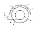
- FIG. 16 is a cross-sectional view showing the configuration of the irradiation apparatus according to the present embodiment.
- an excimer lamp 340 includes a cylindrical inner electrode 342 disposed inside a cylindrical discharge vessel 341 filled with an inert gas.
- a bowl-shaped reflecting mirror 351 made of aluminum is disposed above the excimer lamp 340. The reactive gas flows between the discharge vessel 341 and the reflecting mirror 351 under atmospheric pressure, and the leaked gas flows toward the object to be processed.
- the inner electrode 342 disposed inside the discharge vessel 341 is paired with the reflecting mirror 351 as the other electrode, and is connected to a high frequency power source P that supplies a sinusoidal AC voltage. Since the inner electrode 342 is in a closed space inside the discharge vessel 341, insulation can be easily achieved by setting the inner electrode 342 on the high voltage side and the reflecting mirror 351 on the low voltage side.
- the discharge of the reactive gas layer 352 can be stopped without being sustained, so that even if a sinusoidal AC voltage is supplied, the transition of the plasma discharge to the arc discharge can be prevented and the plasma discharge can be stabilized. Can be maintained.
- the object to be processed can be subjected to both the cleaning process using vacuum ultraviolet light from the excimer lamp 340 and the cleaning process using plasma, a high cleaning processing capability can be obtained for the object to be processed.
- the irradiation apparatus of the present invention can be suitably used for dry cleaning of a substrate such as a wafer or a glass substrate in a manufacturing process of a semiconductor element or a liquid crystal substrate.
Landscapes
- Physics & Mathematics (AREA)
- Engineering & Computer Science (AREA)
- Plasma & Fusion (AREA)
- Spectroscopy & Molecular Physics (AREA)
- Electromagnetism (AREA)
- Physical Or Chemical Processes And Apparatus (AREA)
- Cleaning In General (AREA)
- Cleaning Or Drying Semiconductors (AREA)
Abstract
高い洗浄処理能力を得ると共に、結合エネルギーが高い化学結合を有する有機化合物についても確実に除去することができる照射装置を提供する。放電容器(111)及び一対の電極(112、113)を有するエキシマランプ(110)と、一方の電極(112)に誘電体を介して対向するよう配置されたプラズマ放電用電極(125)とを備え、一方の電極(112)及びプラズマ放電用電極(125)を介してプラズマ発生回路が形成されてなり、エキシマランプ(110)における一対の電極間(112、113)に印加される高周波電界によって放電容器(111)内にエキシマ放電が発生されると共に、エキシマランプ(110)とプラズマ放電用電極(125)との間にプラズマ発生用反応性ガスが流過された状態で、一方の電極(112)とプラズマ放電用電極(125)との間に印加された高周波電界によってプラズマ放電が発生させる。
Description
本発明は、半導体素子や液晶基板の製造工程において、ウエハやガラス基板等の基板のドライ洗浄に好適に用いることができる照射装置に関する。
半導体素子や液晶基板の製造工程においては、シリコンウエハやガラス基板等の基板の表面に付着した有機化合物等の除去処理が行われており、かかる有機化合物等の除去処理方法としては、水や有機溶剤等を使用しないドライ洗浄法が広く利用されている。
このようなドライ洗浄法としては、被処理体の表面に波長200nm以下の真空紫外線を照射することにより、該被処理体の表面に付着した有機化合物を分解すると共にオゾン等の活性酸素によって酸化して除去する光洗浄法(特許文献1参照。)や、大気圧近傍の圧力下において、窒素ガス等のプラズマ発生用反応性ガスを流過させながら高周波電界を印加することによってプラズマを発生させ、このプラズマによって被処理体の表面に付着した有機化合物を分解・酸化して除去するプラズマ洗浄法(特許文献2参照。)が知られている。
このようなドライ洗浄法としては、被処理体の表面に波長200nm以下の真空紫外線を照射することにより、該被処理体の表面に付着した有機化合物を分解すると共にオゾン等の活性酸素によって酸化して除去する光洗浄法(特許文献1参照。)や、大気圧近傍の圧力下において、窒素ガス等のプラズマ発生用反応性ガスを流過させながら高周波電界を印加することによってプラズマを発生させ、このプラズマによって被処理体の表面に付着した有機化合物を分解・酸化して除去するプラズマ洗浄法(特許文献2参照。)が知られている。
光洗浄法としては、放電容器内に、例えば、キセノンが封入されたエキシマランプを備えた照射装置を用い、該照射装置からの紫外線が照射される照射領域を被処理体を通過させることにより、該被処理体の洗浄処理が行われる。
また、プラズマ洗浄法においては、プラズマは、大気圧下では一瞬にしてグロー放電からアーク放電に移行し、スパーク放電が発生しやすい。そのため、短パルスの電界を電極に印加して、グロー放電からアーク放電に移行する前に、強制的に電界を切替えて、アーク放電に移行しないようにし、グロー放電のまま維持させるようにしている。
しかしながら、従来の照射装置においては、以下のような問題がある。
液晶基板においては、サイズの大きい大型のものの開発が進み、このような液晶基板等の被処理体の大型化に伴い、被処理体の有機化合物等の除去処理を高い効率で行うために、被処理体の移動速度を上げることにより、処理速度を向上することが要請されている。しかしながら、従来の照射装置では、被処理体の処理速度が高い場合には、該被処理体に対する真空紫外線の照射時間が短くなるため、高い洗浄処理能力を得ることが困難である、という問題がある。
また、結合エネルギーが高い化学結合を有する有機化合物においては、該化学結合を真空紫外線のエネルギーでは切断することができないため、このような有機化合物について真空紫外線による光洗浄処理だけでは除去することが困難である、という問題がある。
液晶基板においては、サイズの大きい大型のものの開発が進み、このような液晶基板等の被処理体の大型化に伴い、被処理体の有機化合物等の除去処理を高い効率で行うために、被処理体の移動速度を上げることにより、処理速度を向上することが要請されている。しかしながら、従来の照射装置では、被処理体の処理速度が高い場合には、該被処理体に対する真空紫外線の照射時間が短くなるため、高い洗浄処理能力を得ることが困難である、という問題がある。
また、結合エネルギーが高い化学結合を有する有機化合物においては、該化学結合を真空紫外線のエネルギーでは切断することができないため、このような有機化合物について真空紫外線による光洗浄処理だけでは除去することが困難である、という問題がある。
また、プラズマ洗浄法において使用する、短パルスの電界を生成するパルス電源は高価であるため、装置全体の価格が上昇してしまうという問題がある。また、短パルス電界を印加する場合は、処理物であるガラス基板との走行位置とのタイミングを図る複雑な制御が必要となることや、急峻な電界が発生することからノイズの問題も生じる。
本発明の目的は、以上のような事情に鑑み、高い洗浄処理能力を得ることができ、しかも、結合エネルギーが高い化学結合を有する有機化合物についても確実に除去することができる照射装置を提供することにある。
また、本発明の他の目的は、グロー放電からアーク放電への移行を防止することができ、かつ、パルス電源を使うことの種々の問題を解決できる新しい大気圧プラズマ発生装置を提供することにある。
また、本発明の他の目的は、グロー放電からアーク放電への移行を防止することができ、かつ、パルス電源を使うことの種々の問題を解決できる新しい大気圧プラズマ発生装置を提供することにある。
本願第1の発明は、放電容器及び一対の電極を有するエキシマランプと、該エキシマランプにおける一方の電極に誘電体を介して対向するよう配置されたプラズマ放電用電極とを備え、前記エキシマランプにおける前記一方の電極及び前記プラズマ放電用電極を介してプラズマ発生回路が形成されてなり、前記エキシマランプにおける一対の電極間に印加される高周波電界によって前記放電容器内にエキシマ放電が発生されると共に、前記エキシマランプと前記プラズマ放電用電極との間にプラズマ発生用反応性ガスが流過された状態で、前記エキシマランプにおける前記一方の電極と前記プラズマ放電用電極との間に印加された高周波電界によってプラズマ放電が発生されることを特徴とする照射装置である。
本願第2の発明は、第1の発明において、前記誘電体の表面に、電界集中用凸部が形成されていることを特徴とする照射装置である。
本願第3の発明は、第1又は第2の発明において、前記プラズマ放電用電極の表面に、電界集中用凸部が形成されていることを特徴とする照射装置である。
本願第4の発明は、第1の発明乃至第3の発明のいずれか1つの発明において、前記エキシマランプが配置されるランプハウスを備えてなり、該ランプハウスに前記プラズマ放電用電極が一体に設けられていることを特徴とする照射装置である。
本願第5の発明は、第1の発明乃至第4の発明のいずれか1つの発明において、エキシマ放電のための高周波電源によって前記プラズマ放電が発生されることを特徴とする照射装置である。
本願第6の発明は、交流電界が供給される一対の電極に挟まれる空間に、大気圧下に反応性ガスが流過されている反応性ガス層と放電容器の内部に不活性ガスが封入された不活性ガス層とが、前記電極に対して並行で連続するように配置されてなり、前記電極間で発生する放電が反応性ガス層におけるプラズマ放電と不活性ガス層におけるエキシマ放電とを介して発生することを特徴とする照射装置である。
本願第7の発明は、第6の発明において、前記放電容器に一方の電極が取り付けられ、該放電容器が内部に配置されるランプハウスに他方の電極が取り付けられ、ランプハウスと放電容器との間に反応性ガス層が形成されていることを特徴とする照射装置である。
本願第8の発明は、第7の発明において、前記一方の電極は放電容器の側面に伸びる一方の側面電極を有し、該一方の側面電極に対向する位置に前記他方の電極と同電位になるように電力が供給されている他方の側面電極が取り付けられ、前記一方の側面電極と前記他方の側面電極との間に誘電体を有することを特徴とする照射装置である。
本願第9の発明は、第6の発明において、前記一方の電極よりも大きい面積を有する誘電体を放電容器との間に配置し、前記誘電体の被処理体に対向する面に一方の電極が取り付けられていることを特徴とする照射装置である。
本願第10の発明は、不活性ガスが封入された不活性ガス層が形成された放電容器の内部に配置された内部電極と、前記放電容器の外部に大気圧下に反応性ガスが流過された反応性ガス層を挟んで配置された外部電極との間に交流電界が供給され、前記外部電極と前記内部電極との間で発生する放電が、反応性ガス層におけるプラズマ放電と不活性ガス層におけるエキシマ放電とを介して発生することを特徴とする照射装置である。
本願第11の発明は、第10の発明において、前記内部電極に高電圧が供給されることを特徴とする照射装置である。
本願第2の発明は、第1の発明において、前記誘電体の表面に、電界集中用凸部が形成されていることを特徴とする照射装置である。
本願第3の発明は、第1又は第2の発明において、前記プラズマ放電用電極の表面に、電界集中用凸部が形成されていることを特徴とする照射装置である。
本願第4の発明は、第1の発明乃至第3の発明のいずれか1つの発明において、前記エキシマランプが配置されるランプハウスを備えてなり、該ランプハウスに前記プラズマ放電用電極が一体に設けられていることを特徴とする照射装置である。
本願第5の発明は、第1の発明乃至第4の発明のいずれか1つの発明において、エキシマ放電のための高周波電源によって前記プラズマ放電が発生されることを特徴とする照射装置である。
本願第6の発明は、交流電界が供給される一対の電極に挟まれる空間に、大気圧下に反応性ガスが流過されている反応性ガス層と放電容器の内部に不活性ガスが封入された不活性ガス層とが、前記電極に対して並行で連続するように配置されてなり、前記電極間で発生する放電が反応性ガス層におけるプラズマ放電と不活性ガス層におけるエキシマ放電とを介して発生することを特徴とする照射装置である。
本願第7の発明は、第6の発明において、前記放電容器に一方の電極が取り付けられ、該放電容器が内部に配置されるランプハウスに他方の電極が取り付けられ、ランプハウスと放電容器との間に反応性ガス層が形成されていることを特徴とする照射装置である。
本願第8の発明は、第7の発明において、前記一方の電極は放電容器の側面に伸びる一方の側面電極を有し、該一方の側面電極に対向する位置に前記他方の電極と同電位になるように電力が供給されている他方の側面電極が取り付けられ、前記一方の側面電極と前記他方の側面電極との間に誘電体を有することを特徴とする照射装置である。
本願第9の発明は、第6の発明において、前記一方の電極よりも大きい面積を有する誘電体を放電容器との間に配置し、前記誘電体の被処理体に対向する面に一方の電極が取り付けられていることを特徴とする照射装置である。
本願第10の発明は、不活性ガスが封入された不活性ガス層が形成された放電容器の内部に配置された内部電極と、前記放電容器の外部に大気圧下に反応性ガスが流過された反応性ガス層を挟んで配置された外部電極との間に交流電界が供給され、前記外部電極と前記内部電極との間で発生する放電が、反応性ガス層におけるプラズマ放電と不活性ガス層におけるエキシマ放電とを介して発生することを特徴とする照射装置である。
本願第11の発明は、第10の発明において、前記内部電極に高電圧が供給されることを特徴とする照射装置である。
本願第1~5の発明に係る照射装置によれば、被処理体に対して、エキシマランプからの紫外線による洗浄処理及びエキシマランプとプラズマ放電用電極との間に発生したプラズマによる洗浄処理の両方を行うことができるので、被処理体に対して高い洗浄処理能力が得られ、紫外線による洗浄処理のみでは除去することが困難な結合エネルギーが高い化学結合を有する有機化合物についても、プラズマによる洗浄処理によって酸化されるため、確実に除去することができる。
また、本願第6及び第7の発明に係る照射装置によれば、一対の電極で発生する放電が反応性ガス層と不活性ガス層とを介して生じるようにすることによって、反応性ガス層の放電を持続させずに停止できるので、正弦波交流電圧を供給してもプラズマ放電のアーク放電への移行を防止でき、プラズマ放電を安定に維持することができる。また、被処理体に対して、エキシマランプからの紫外線による洗浄処理およびエキシマランプと電極との間に発生したプラズマによる洗浄処理の両方を行うことができるので、被処理体に対して高い洗浄処理能力が得られる。
また、本願第8の発明に係る照射装置によれば、ランプハウスと放電容器との間に反応性ガス層が形成されているため、放電容器の側面に伸びる一方の側面電極と、電極と同電位になるように電力が供給されている他方の側面電極との間でプラズマ放電が発生する。そのため、プラズマをより多く含むガスを被処理体Wに照射でき、被処理体Wの表面に付着した有機化合物がより効率よく分解・酸化される。
また、本願第9の発明に係る照射装置によれば、電極よりも大きい面積を有する誘電体を放電容器との間に配置し、誘電体の被処理体に対向する面に電極が取り付けることによって、電極同士がエキシマランプの放電容器の側面を放電が走り、沿面でアークショートしないようにすることができる。
また、本願第10の発明に係る照射装置によれば、一対の電極で発生する放電が反応性ガス層と不活性ガス層とを介して生じるようにすることによって、反応性ガス層の放電を持続させずに停止できるので、正弦波交流電圧を供給してもプラズマ放電のアーク放電への移行を防止でき、プラズマ放電を安定に維持することができる。また、被処理体に対して、エキシマランプからの紫外線による洗浄処理およびエキシマランプと電極との間に発生したプラズマによる洗浄処理の両方を行うことができるので、被処理体に対して高い洗浄処理能力が得られる。
また、本願第11の発明に係る照射装置によれば、内側電極は放電容器の内部の閉じられた空間内にあるので、内側電極を高圧側とすることによって、容易に絶縁を図ることができる。
また、本願第6及び第7の発明に係る照射装置によれば、一対の電極で発生する放電が反応性ガス層と不活性ガス層とを介して生じるようにすることによって、反応性ガス層の放電を持続させずに停止できるので、正弦波交流電圧を供給してもプラズマ放電のアーク放電への移行を防止でき、プラズマ放電を安定に維持することができる。また、被処理体に対して、エキシマランプからの紫外線による洗浄処理およびエキシマランプと電極との間に発生したプラズマによる洗浄処理の両方を行うことができるので、被処理体に対して高い洗浄処理能力が得られる。
また、本願第8の発明に係る照射装置によれば、ランプハウスと放電容器との間に反応性ガス層が形成されているため、放電容器の側面に伸びる一方の側面電極と、電極と同電位になるように電力が供給されている他方の側面電極との間でプラズマ放電が発生する。そのため、プラズマをより多く含むガスを被処理体Wに照射でき、被処理体Wの表面に付着した有機化合物がより効率よく分解・酸化される。
また、本願第9の発明に係る照射装置によれば、電極よりも大きい面積を有する誘電体を放電容器との間に配置し、誘電体の被処理体に対向する面に電極が取り付けることによって、電極同士がエキシマランプの放電容器の側面を放電が走り、沿面でアークショートしないようにすることができる。
また、本願第10の発明に係る照射装置によれば、一対の電極で発生する放電が反応性ガス層と不活性ガス層とを介して生じるようにすることによって、反応性ガス層の放電を持続させずに停止できるので、正弦波交流電圧を供給してもプラズマ放電のアーク放電への移行を防止でき、プラズマ放電を安定に維持することができる。また、被処理体に対して、エキシマランプからの紫外線による洗浄処理およびエキシマランプと電極との間に発生したプラズマによる洗浄処理の両方を行うことができるので、被処理体に対して高い洗浄処理能力が得られる。
また、本願第11の発明に係る照射装置によれば、内側電極は放電容器の内部の閉じられた空間内にあるので、内側電極を高圧側とすることによって、容易に絶縁を図ることができる。
本発明の第1の実施形態を図1~図7を用いて説明する。
図1は、本実施形態に係る照射装置の構成を示す断面図である。
同図に示すように、この照射装置は、例えば、液晶基板等の被処理体の表面をドライ洗浄処理するために用いられるものであって、波長200nm以下の真空紫外線を放射するエキシマランプ110を有し、このエキシマランプ110は、下面が開口された矩形の箱型のランプハウス120内に配置されている。また、エキシマランプ110の下方には、被処理体Wを水平方向に搬送して移動させる搬送機構130が設けられている。この搬送機構130は、複数の搬送コロ131が被処理体の搬送方向に沿って並ぶよう配置されて構成されている。
図1は、本実施形態に係る照射装置の構成を示す断面図である。
同図に示すように、この照射装置は、例えば、液晶基板等の被処理体の表面をドライ洗浄処理するために用いられるものであって、波長200nm以下の真空紫外線を放射するエキシマランプ110を有し、このエキシマランプ110は、下面が開口された矩形の箱型のランプハウス120内に配置されている。また、エキシマランプ110の下方には、被処理体Wを水平方向に搬送して移動させる搬送機構130が設けられている。この搬送機構130は、複数の搬送コロ131が被処理体の搬送方向に沿って並ぶよう配置されて構成されている。
エキシマランプ110は、エキシマ用ガスが気密に封入された矩形の箱型の放電容器111を有する。この放電容器111における上部側部分111aの外面(図1において上面)には、膜状の一方の電極112が設けられ、放電容器111における下部側部分111bの外面(図1において下面)には、網状の他方の電極113が設けられており、一方の電極112及び他方の電極113の各々は、高周波電源Pに接続されている。図示の例では、一方の電極112が高圧側電極とされ、他方の電極113が接地側電極とされている。
放電容器111を構成する材料としては、真空紫外線を良好に透過するもの、具体的には、合成石英ガラス等のシリカガラス、サファイアガラス等を用いることができる。一方の電極112及び他方の電極113を構成する材料としては、アルミニウム、ニッケル、金等の金属材料を用いることができる。また、一方の電極112及び他方の電極113は、前記の金属材料を含む導電性ペーストをスクリーン印刷することにより、又は前記の金属材料を真空蒸着することにより、形成することができる。放電容器111内に封入されるエキシマ用ガスとしては、真空紫外線を放射するエキシマを生成し得るもの、具体的には、キセノン、アルゴン、クリプトン等の希ガス、又は、希ガスと、臭素、塩素、ヨウ素、フッ素等のハロゲンガスとを混合した混合ガス等を用いることができる。また、エキシマ用ガスの封入圧は、例えば、10~80kPaである。
エキシマランプ110における一方の電極112には、一方の電極112を覆うようにプラズマ放電用誘電体膜115が形成されている。プラズマ放電用誘電体膜115を構成する材料としては、アルミナ(Al2 O3 )、シリカ(SiO2 )等の誘電体材料を用いることができる。また、プラズマ放電用誘電体膜115は、一方の電極112の表面に前記の誘電体材料を溶射又は溶着することにより形成することができる。
放電容器111における上部側部分111a及び下部側部分111bの各々の厚みは、0.5~5mmであることが好ましい。また、放電容器111内における放電容器111における上部側部分111a及び下部側部分111bとの距離(放電ギャップ)は、0.05~5mmであることが好ましい。また、プラズマ放電用誘電体膜115の厚みは、0.01~4mmであることが好ましい。この厚みが過小である場合には、プラズマ放電用誘電体膜115とプラズマ放電用電極125との間にアーク放電が生じやすくなる。一方、この厚みが過大である場合には、プラズマ放電用誘電体膜115とプラズマ放電用電極125との間にプラズマ放電を発生させることが困難となる。
ランプハウス120は、側壁を形成する矩形の筒状の側壁部材121と、側壁部材121の上部の開口を塞ぐ上板122とにより構成されている。上板122の内面には、例えば、アルミニウムよりなる直方体状のプラズマ放電用電極125が上板122に一体に設けられている。このプラズマ放電用電極125には、それぞれ水平方向(図1において紙面に垂直な方向)に貫通して伸びる複数の冷却水管126が設けられている。エキシマランプ110が、一方の電極112にプラズマ放電用誘電体膜115を介してプラズマ放電用電極125が対向するよう、ランプハウス120内に固定板123によって固定配置されると共に、プラズマ放電用電極125が接地されることにより、エキシマランプ110における一方の電極112及びプラズマ放電用電極125を介してプラズマ発生回路が形成される。図示の例では、エキシマランプ110におけるエキシマ放電のための高周波電源Pによってプラズマ放電が発生される構成、すなわち、エキシマ放電及びプラズマ放電の両方が共通の高周波電源Pによって行われる構成となっている。また、上板122の内面におけるプラズマ放電用電極125に隣接する位置には、エキシマランプ110における一方の電極112とプラズマ放電用電極125との間にプラズマ発生用反応性ガスを供給するためのマニホールド127が設けられ、エキシマランプ110の側方位置には、一方の電極112とプラズマ放電用電極125との間を流過したガスを下方に案内する案内部材128が設けられている。
プラズマ放電用誘電体膜115とプラズマ放電用電極125との離間距離は、1~10mmであることが好ましい。この離間距離が過小である場合には、プラズマ放電用誘電体膜115とプラズマ放電用電極125との間にプラズマ発生用反応性ガスを流過させることが困難となることがある。一方、この離間距離が過大である場合には、エキシマランプ110における一方の電極112とプラズマ放電用電極125との間に、プラズマ放電を発生させることが困難となることがある。
当該照射装置においては、プラズマ放電用誘電体膜115とプラズマ放電用電極125との間に、大気圧又はその近傍の圧力下において、マニホールド127からプラズマ発生用反応性ガスが供給されて流過される。プラズマ発生用反応性ガスとしては、窒素ガス(N2 )、アルゴンガス(Ar)、炭酸ガス(CO2 )、ヘリウムガス(He)等を主成分とし、酸素ガスが1~2体積%含有してなるものを用いることが好ましい。また、プラズマ発生用反応性ガスの単位長さ当りの流量は、1m当り0.5~4m3 /sであることが好ましい。
エキシマランプ110における一方の電極112と他方の電極113との間には、一方の電極112を高圧側電極とし、他方の電極113を接地側電極として、高周波電源Pによって高周波電界が印加され、この高周波電界によって、エキシマランプ110における放電容器111内においてエキシマ放電が発生し、このエキシマ放電によってエキシマ用ガスに由来するエキシマ分子が形成され、これにより、真空紫外線が放射される。一方、エキシマランプ110における一方の電極112とプラズマ放電用電極125との間には、一方の電極112を高圧側電極とし、プラズマ放電用電極125を接地側電極として、大気圧又はその近傍の圧力下において、高周波電源Pによって高周波電界が印加され、この高周波電界によって、プラズマ放電用誘電体膜115とプラズマ放電用電極125との間にプラズマ放電(グロー放電)が発生し、このプラズマ放電によってプラズマ発生用反応性ガスが電離または励起されてプラズマが生成される。
以上において、高周波電源Pから供給される電力は、その周波数が10~100kHzの高周波であることが好ましく、その電圧は1kVrms~数10kVrmsの高電圧であることが好ましい。これにより、プラズマ放電用誘電体膜115とプラズマ放電用電極125との間の放電状態が、グロー放電からアーク放電に移行することがなく、プラズマ放電を安定に維持することができる。また、エキシマ放電及びプラズマ放電の開始電圧は、放電空間の圧力、放電ギャップの大きさ、ガスの種類等によって定まるが、プラズマ放電の開始電圧がエキシマ放電の開始電圧が高く、プラズマ放電がエキシマ放電より例えば数マイクロ秒間遅延して発生するよう設定されることが好ましい。このような条件が満足されることにより、エキシマ放電による真空紫外線が放射されることによって光電子が生ずるため、プラズマ放電を容易にかつ安定に発生させることができる。
エキシマランプ110の下方において、搬送機構130によって水平方向に移動する被処理体Wの表面に、エキシマランプ110から放射された真空紫外線が照射されると共に、真空紫外線によって発生したオゾン等の活性酸素が被処理体Wの表面に接触することにより、被処理体Wの表面に付着した有機化合物が分解・酸化される。更に、プラズマ放電用誘電体膜115とプラズマ放電用電極125との間で生成したプラズマを含むガスが、エキシマランプ110の側面と案内部材128によって下方に導かれ、搬送機構130によって水平方向に移動する被処理体Wの表面に接触することにより、被処理体Wの表面に付着した有機化合物が分解・酸化される。ここで、有機化合物中におけるC-C結合、C-H結合、C=C結合等の化学結合は、結合エネルギーが比較的に低いため、真空紫外線のエネルギーによって切断することができ、更に、真空紫外線によって発生した活性酸素と反応することによって酸化してガス化することができる。一方、C=O結合等の化学結合は、結合エネルギーが高いため、真空紫外線のエネルギーによって切断することができないが、プラズマ放電によって発生した酸素ラジカル等によって酸化してガス化することができる。このようして、被処理体Wについて、真空紫外線による洗浄処理及びプラズマによる洗浄処理が行われる。
当該照射装置によれば、被処理体Wに対して、エキシマランプ110からの真空紫外線による洗浄処理、及びエキシマランプ110における一方の電極112とプラズマ放電用電極125との間に発生したプラズマによる洗浄処理の両方を行うことができるので、被処理体Wに対して高い洗浄処理能力が得られる。また、真空紫外線による洗浄処理のみでは除去することが困難な結合エネルギーが高い化学結合を有する有機化合物についても、プラズマによる洗浄処理によって酸化されてガス化されるため、確実に除去することができる。
本実施形態に係る照射装置においては、図1に示した構成に限定されず、下記(1)~(6)に説明するように、種々の変更を加えることが可能である。
(1)図2に示すように、プラズマ放電用誘電体膜115の表面に、多数の電界集中用凸部115aを形成することができる。また、図3に示すように、プラズマ放電用電極125の表面に多数の電界集中用凸部125aを形成することができる。このような照射装置においては、プラズマ放電用誘電体膜115の電界集中用凸部115aとプラズマ放電用電極125とが、又はプラズマ放電用誘電体膜115とプラズマ放電用電極125の電界集中用凸部125aとが離間していても接触していてもよく、その離間距離が2mm以下であることが好ましい。また、プラズマ放電用誘電体膜115の電界集中用凸部115a又はプラズマ放電用電極125の電界集中用凸部125aの突出高さは、それぞれ3~10mmであることが好ましい。
このような構成によれば、プラズマ放電用誘電体膜115の電界集中用凸部115aとプラズマ放電用電極125との間、又はプラズマ放電用誘電体膜115とプラズマ放電用電極125の電界集中用凸部125aとの間に高周波電界が集中して発生し、沿面放電及び平等電界型放電が複合した放電状態が得られるため、プラズマ放電のための始動開始電圧を低くすることができ、また、作動中に放電容器111の熱膨張が生じることによりプラズマ放電用誘電体膜115とプラズマ放電用電極125との距離が変化した場合にも、プラズマ放電を安定に維持することができる。
このような構成によれば、プラズマ放電用誘電体膜115の電界集中用凸部115aとプラズマ放電用電極125との間、又はプラズマ放電用誘電体膜115とプラズマ放電用電極125の電界集中用凸部125aとの間に高周波電界が集中して発生し、沿面放電及び平等電界型放電が複合した放電状態が得られるため、プラズマ放電のための始動開始電圧を低くすることができ、また、作動中に放電容器111の熱膨張が生じることによりプラズマ放電用誘電体膜115とプラズマ放電用電極125との距離が変化した場合にも、プラズマ放電を安定に維持することができる。
(2)専用のプラズマ放電用電極を設けずに、ランプハウスの一部、例えば、図4に示すように、ランプハウス120における上板122をプラズマ放電用電極125として利用することができ、このような構成においては、図5に示すように、上板122を蛇腹状に形成することにより、電界集中用凸部125aを形成することができる。
(3)図6に示すように、プラズマ放電用誘電体膜115は、プラズマ放電用電極125の表面に形成されていてもよい。
(4)図7に示すように、エキシマランプ110における一方の電極112は、放電容器111の内部に配置されていてもよい。このような構成においては、エキシマランプ110における放電容器111の上部側部分111aをプラズマ放電用の誘電体として利用することができる。
このような構成によれば、一方の電極112と放電容器111における下部側部分111bとの間にエキシマ放電が発生すると共に、一方の電極112と放電容器111における上部側部分111aとの間にエキシマ放電が発生する。従って、一方の電極112とプラズマ放電用電極125との間には、エキシマ放電およびプラズマ放電の両方が発生した状態となるため、放電状態の制御が容易となる。
このような構成によれば、一方の電極112と放電容器111における下部側部分111bとの間にエキシマ放電が発生すると共に、一方の電極112と放電容器111における上部側部分111aとの間にエキシマ放電が発生する。従って、一方の電極112とプラズマ放電用電極125との間には、エキシマ放電およびプラズマ放電の両方が発生した状態となるため、放電状態の制御が容易となる。
(5)図1に示す照射装置においては、エキシマ放電およびプラズマ放電の両方が共通の高周波電源Pによって行う構成とされているが、プラズマ放電のための高周波電源が、エキシマランプ110におけるエキシマ放電のための高周波電源と別個に設けられた構成であってもよい。
(6)図1に示す照射装置においては、エキシマランプ110における一方の電極112が高圧側電極とされ、プラズマ放電用電極125が接地側電極とされているが、プラズマ放電用電極125が高圧側電極とされた構成であってもよい。
次に、本発明の第2の実施形態を図8~図10を用いて説明する。
図8は、第2の実施形態に係る照射装置の構成を示す断面図である。
同図に示すように、ランプハウス220の内部に、エキシマランプ210が配置され、エキシマランプ210の下方に被処理体Wを水平方向に搬送して移動させる搬送機構230が設けられている。ランプハウス220は、側壁を形成する側壁部材221a、221bが向かい合うように配置され、側壁部材221a、221bの上部の開口を塞ぐように天板222が形成されている。ランプハウス220を、側壁部材221a、221bと天板222とに分けて構成することにより、天板222を開閉式にしてランプハウス220内部に配置されるエキシマランプ210を交換できるようにしている。搬送機構230は、複数の搬送コロ231が被処理体Wの搬送方向に沿って並ぶよう配置されて構成されている。
図8は、第2の実施形態に係る照射装置の構成を示す断面図である。
同図に示すように、ランプハウス220の内部に、エキシマランプ210が配置され、エキシマランプ210の下方に被処理体Wを水平方向に搬送して移動させる搬送機構230が設けられている。ランプハウス220は、側壁を形成する側壁部材221a、221bが向かい合うように配置され、側壁部材221a、221bの上部の開口を塞ぐように天板222が形成されている。ランプハウス220を、側壁部材221a、221bと天板222とに分けて構成することにより、天板222を開閉式にしてランプハウス220内部に配置されるエキシマランプ210を交換できるようにしている。搬送機構230は、複数の搬送コロ231が被処理体Wの搬送方向に沿って並ぶよう配置されて構成されている。
ランプハウス220の天板222の内面には、例えば、アルミニウムよりなる直方体状のプラズマ放電用電極225が設けられている。プラズマ放電用電極225の内部に、エキシマランプ210の長手方向に沿って水平に伸びる冷却水管226が複数設けられている。一方の側壁部材221aとプラズマ放電用電極225との間に、エキシマランプ210とプラズマ放電用電極225との間に反応性ガスを供給するためのマニホールド227が設けられている。反応性ガスとしては、窒素ガス(N2)、アルゴンガス(Ar)、炭酸ガス(CO2)、ヘリウムガス(He)等を主成分とし、酸素ガスが1~2体積%含有してなるものを用いることが好ましい。また、単位長さ当りの流量が、1m当り0.5~4m3/sとなるように流過させている。
反応性ガスが、大気圧またはその近傍の圧力下において、マニホールド227からプラズマ放電用電極225とエキシマランプ210との間を流れ、他方の側壁部材221bとの隙間からエキシマランプ210の下方の被処理体Wに向かって流すことによって、発生したプラズマが被処理体Wに照射されるようにしている。反応性ガスが一方の側壁部材221aに沿って流出しないように、エキシマランプ210の側面に接触するように固定板223が配置されている。また、他方の側壁部材221bとの間にはエキシマランプ210の側面との間に反応性ガスが流過する隙間を挟んで案内部材228が配置されている。
エキシマランプ210は、合成石英ガラス等のシリカガラス、サファイア等の真空紫外線を良好に透過する断面矩形状で中空長尺の放電容器211の内部に、希ガス、又は、希ガスとハロゲンガスとを混合した混合ガスよりなる不活性ガスが、例えば、10~80kPaで気密に封入されている。放電容器211の被処理体Wに対向する下面211bの外面に、網状のエキシマ放電用電極213が設けられている。エキシマ放電用電極213は、アルミニウム、ニッケル、金等の金属材料よりなり、これらの金属材料を含む導電性ペーストをスクリーン印刷することや、金属材料を真空蒸着することにより形成される。
プラズマ放電用電極225及びエキシマ放電用電極213は、正弦波交流電圧を供給する高周波電源Pに接続されている。高周波電源Pから供給される電力は、例えば、周波数が10~100kHzであり、電圧が1kVrms~数10kVrmsである。プラズマ放電用電極225とエキシマ放電用電極213との間に、放電容器211の内部に不活性ガスが封入された不活性ガス層214と、大気圧下に反応性ガスが流過する反応性ガス層224とが連続して挟まれるように配置されている。このため、プラズマ放電用電極225とエキシマ放電用電極213との放電は、エキシマランプ210の上面211aを介してプラズマ放電とエキシマ放電とを経ることになる。
不活性ガス層214でエキシマ放電が発生してエキシマ分子が形成され、真空紫外線が放射される。また、反応性ガス層224にかかる高周波電界によってプラズマ放電が発生し、反応性ガス224が電離または励起されてプラズマが生成される。そして、搬送機構230によって水平方向に移動する被処理体Wの表面に、エキシマランプ210から放射された真空紫外線が照射されると共に、真空紫外線によって発生したオゾン等の活性酸素が被処理体Wの表面に接触することにより、被処理体Wの表面に付着した有機化合物が分解・酸化される。更に、プラズマを含むガスが、エキシマランプ210の側面と案内部材228によって下方に導かれ、被処理体Wの表面に接触することにより、被処理体Wの表面に付着した有機化合物が分解・酸化される。被処理体Wに対して、エキシマランプ210からの真空紫外線による洗浄処理、及びプラズマによる洗浄処理の両方を行うことができるので、被処理体Wに対して高い洗浄処理能力が得られる。
エキシマ放電及びプラズマ放電の開始電圧は、放電空間の圧力、放電ギャップの大きさ、ガスの種類等によって定まるが、プラズマ放電の開始電圧の方がエキシマ放電の開始電圧よりも高く、プラズマ放電がエキシマ放電より、例えば、数マイクロ秒間遅延して発生するよう設定されることが好ましい。このような条件が満たすように、反応性ガス層224と不活性ガス層214の放電ギャップの大きさや、不活性ガス層214のガス圧が設定される。例えば、反応性ガス層224の放電ギャップの大きさとなるエキシマランプ210とプラズマ放電用電極225との離間距離を1~10mmとし、不活性ガス層214の放電ギャップとなる放電容器211の上面211aと下面211bとの距離を0.05~5mmとする。
プラズマ放電用電極225を高電圧発生側として正弦波交流電圧を供給した場合について説明する。エキシマ放電用電極213に印加された高電圧により、エキシマランプ210の下面211bに電荷が充電され、蓄えられた電荷による電圧がエキシマ放電の開始電圧に達すると、不活性ガス層214でエキシマ放電が発生する。さらに、不活性ガス層214でのエキシマ放電により、エキシマランプ210の上面211aに電荷がさらに充電され、プラズマ放電の放電開始電圧に達すると、反応性ガス層224でプラズマ放電が発生する。しかしながら、不活性ガス層214では、エキシマ放電によりエキシマランプ210の上面211aと下面211bとの間の電圧が低下するため、放電が維持することなく停止する。さらに、エキシマ放電の停止により、反応性ガス層224への電流が制限されてプラズマ放電も停止する。印加される高圧電圧をさらに上昇させていくと、上記状態が最大電圧に到達するまで繰り返し発生して放電する。反応性ガス層224の放電を持続させずに停止できるので、アーク放電への移行を防止できる。プラズマ放電用電極225の極性が反転することによって、上記放電が再び生じる。
プラズマ放電用電極225とエキシマ放電用電極213との間に挟まれる空間に、反応性ガス層224と不活性ガス層214とが電極213、225に対して並ぶよう配置することによって、一対の電極225、213で発生する放電が反応性ガス層224と不活性ガス層214とを介して生じるようにしている。このような構成にすることによって、反応性ガス層224の放電を持続させずに停止できるので、正弦波交流電圧を供給してもプラズマ放電のアーク放電への移行を防止でき、プラズマ放電を安定に維持することができる。
図9は、第2の実施形態に係る照射装置において、プラズマ放電用電極225の設置位置を変更した照射装置の構成を示す断面図である。
図8において、プラズマ放電用電極225をランプハウス220の内部に配置して、プラズマ放電用電極225に高電圧を供給する場合、ランプハウス220やその他の部材と絶縁をとることが困難となる場合がある。そのような問題を回避するため、図9に示すように、ランプハウス220の天板222とは別体に、天板222から吊り下げるようにしてプラズマ放電用電極225を配置している。このような構成にすることによって、プラズマ放電用電極225の絶縁がとりやすくなる。
図8において、プラズマ放電用電極225をランプハウス220の内部に配置して、プラズマ放電用電極225に高電圧を供給する場合、ランプハウス220やその他の部材と絶縁をとることが困難となる場合がある。そのような問題を回避するため、図9に示すように、ランプハウス220の天板222とは別体に、天板222から吊り下げるようにしてプラズマ放電用電極225を配置している。このような構成にすることによって、プラズマ放電用電極225の絶縁がとりやすくなる。
図10は、第2の実施形態に係る照射装置において、エキシマ放電用電極213を誘電体215を介して設置した照射装置の構成を示す断面図である。
同図に示すように、エキシマ放電用電極213を放電容器211に直接に取り付けるのではなく、エキシマ放電用電極213より大きい面積を有する誘電体215を放電容器211との間に配置し、誘電体215の被処理体Wに対向する面にエキシマ放電用電極213が取り付けられている。このように誘電体215を介することによって、エキシマ放電用電極213とプラズマ放電用電極225とが、エキシマランプ210の放電容器211の側面を放電が走り、沿面でアークショートしないようにすることができる。
同図に示すように、エキシマ放電用電極213を放電容器211に直接に取り付けるのではなく、エキシマ放電用電極213より大きい面積を有する誘電体215を放電容器211との間に配置し、誘電体215の被処理体Wに対向する面にエキシマ放電用電極213が取り付けられている。このように誘電体215を介することによって、エキシマ放電用電極213とプラズマ放電用電極225とが、エキシマランプ210の放電容器211の側面を放電が走り、沿面でアークショートしないようにすることができる。
誘電体215とエキシマランプ210との間にも反応性ガスを流過させることによって、プラズマ放電用電極225とエキシマ放電用電極213との間で発生する放電は、誘電体とエキシマランプ210との間で生じるプラズマ放電が加わり、プラズマ放電が生じる反応性ガス層224に挟まれて、エキシマ放電が生じる不活性ガス層214が存在することになる。
次に、本発明の第3の実施形態を図11~図13を用いて説明する。
図11は、本実施形態に係る照射装置の構成を示す断面図である。
同図に示すように、エキシマランプ240は、外側管243と内側管242とが同軸上に配置された二重管構造の放電容器241を有し、外側管243と内側管242に囲まれる空間に不活性ガスが封入されて構成されている。エキシマランプ240の上方にアルミニウムよりなる樋状の反射鏡251が配置されている。エキシマランプ240と反射鏡251との間には、反応性ガスが大気圧下において流過され、漏れ出たガスが被処理体に向かって流れ出るようになっている。
図11は、本実施形態に係る照射装置の構成を示す断面図である。
同図に示すように、エキシマランプ240は、外側管243と内側管242とが同軸上に配置された二重管構造の放電容器241を有し、外側管243と内側管242に囲まれる空間に不活性ガスが封入されて構成されている。エキシマランプ240の上方にアルミニウムよりなる樋状の反射鏡251が配置されている。エキシマランプ240と反射鏡251との間には、反応性ガスが大気圧下において流過され、漏れ出たガスが被処理体に向かって流れ出るようになっている。
エキシマランプ240の内側管242の内周面に、円筒状の金属部材よりなる内側電極244が形成されており、反射鏡251を他方の電極として、正弦波交流電圧を供給する高周波電源Pが接続されている。内側電極244は内側管242の内側の閉じられた空間内にあるので、内側電極244を高圧側とし、反射鏡251を低圧側とすることによって、容易に絶縁を図ることができる。
内側電極244の上半分側は、反射鏡251との間に、放電容器241の内部に不活性ガスが封入された不活性ガス層245と、大気圧下に反応性ガスが流過する反応性ガス層252とが連続して挟まれるように配置されている。このような構成にすることによって、反応性ガス層252の放電を持続させずに停止できるので、正弦波交流電圧を供給してもプラズマ放電のアーク放電への移行を防止でき、プラズマ放電を安定に維持することができる。また、被処理体に対して、エキシマランプ240からの真空紫外線による洗浄処理、及びプラズマによる洗浄処理の両方を行うことができるので、被処理体に対して高い洗浄処理能力が得られる。
図12は、第3の実施形態に係る照射装置において、放電容器241の下側半分に外部電極246が取り付けられた照射装置の構成を示す断面図である。
同図に示すように、エキシマランプ240の放電容器241の外側管243の下側半分に外部電極246を取り付け、外部電極246にアースをとっている。放電容器241の下側半分に封入されている不活性ガスに、内側電極244と外側電極246に挟まれて高電圧がかけられ、エキシマ放電する。図11に示した照射装置では、内側電極244の上半分側しか放電に寄与しなかったが、図12に示した照射装置においては、外側管243の下側半分に外部電極246を取り付けることによって、内側電極244の下半分側も放電に寄与するようにでき、被処理体に対して洗浄処理能力を高めることができる。
同図に示すように、エキシマランプ240の放電容器241の外側管243の下側半分に外部電極246を取り付け、外部電極246にアースをとっている。放電容器241の下側半分に封入されている不活性ガスに、内側電極244と外側電極246に挟まれて高電圧がかけられ、エキシマ放電する。図11に示した照射装置では、内側電極244の上半分側しか放電に寄与しなかったが、図12に示した照射装置においては、外側管243の下側半分に外部電極246を取り付けることによって、内側電極244の下半分側も放電に寄与するようにでき、被処理体に対して洗浄処理能力を高めることができる。
図13は、第3の実施形態に係る照射装置において、反射鏡251ではなく、放電容器241の全周を覆う網状電極247が取り付けられた照射装置の構成を示す断面図である。
同図に示すように、放電容器241の周囲を、反応性ガス層252を介して全周を覆うように網状電極247が取り付けられている。内側電極244の全周に対して、不活性ガス層245と反応性ガス層252とを介して網状電極247が挟むように形成されている。このような網状電極247を構成することによって、内側電極244を取り囲む全ての領域でエキシマ放電とプラズマ放電とを発生させることができる。
同図に示すように、放電容器241の周囲を、反応性ガス層252を介して全周を覆うように網状電極247が取り付けられている。内側電極244の全周に対して、不活性ガス層245と反応性ガス層252とを介して網状電極247が挟むように形成されている。このような網状電極247を構成することによって、内側電極244を取り囲む全ての領域でエキシマ放電とプラズマ放電とを発生させることができる。
次に、本発明の第4の実施形態を図14を用いて説明する。
図14は、本実施形態に係る照射装置の構成を示す断面図である。
同図に示すように、この照射装置は、反応性ガスをエキシマランプ210の下方の被処理体Wに向かって流れるように案内する案内部材228に側面電極229が取り付けられ、プラズマ放電用電極225と同電位になるように電力が供給されている。案内部材228の表面に、アルミナ(Al2O3)、シリカ(SiO2)等の誘電体材料よりなる誘電体219が形成されている。放電容器211の下面211bに形成されたエキシマ放電用電極213は、案内部材228に向かい合う側面212まで伸びるように形成されている。
図14は、本実施形態に係る照射装置の構成を示す断面図である。
同図に示すように、この照射装置は、反応性ガスをエキシマランプ210の下方の被処理体Wに向かって流れるように案内する案内部材228に側面電極229が取り付けられ、プラズマ放電用電極225と同電位になるように電力が供給されている。案内部材228の表面に、アルミナ(Al2O3)、シリカ(SiO2)等の誘電体材料よりなる誘電体219が形成されている。放電容器211の下面211bに形成されたエキシマ放電用電極213は、案内部材228に向かい合う側面212まで伸びるように形成されている。
エキシマランプ210と案内部材228の間には反応性ガスが流過しているので、側面212まで伸びたエキシマ放電用電極213と誘電体219を介して対向する側面電極229との間で、プラズマ放電が発生する。反応性ガスが被処理体Wの表面に接触する直前でプラズマ放電を発生させることによって、プラズマをより多く含むガスを被処理体Wに照射でき、被処理体Wの表面に付着した有機化合物がより効率よく分解・酸化される。
次に、本発明の第5の実施形態を図15を用いて説明する。
図15は、本実施形態に係る照射装置の構成を示す断面図である。
同図に示すように、この照射装置は、ランプハウス320の内部に、エキシマランプ310が配置され、エキシマランプ310の下方に被処理体Wを水平方向に搬送して移動させる搬送機構330が設けられている。ランプハウス320は、側壁を形成する側壁部材321a、321bが向かい合うように配置され、側壁部材321a、321bの上部の開口を塞ぐように天板322が形成されている。ランプハウス320を、側壁部材321a、321bと天板322とに分けて構成することにより、天板322を開閉式にしてランプハウス320内部に配置されるエキシマランプ310を交換できるようにしている。搬送機構330は、複数の搬送コロ331が被処理体Wの搬送方向に沿って並ぶよう配置されて構成されている。
図15は、本実施形態に係る照射装置の構成を示す断面図である。
同図に示すように、この照射装置は、ランプハウス320の内部に、エキシマランプ310が配置され、エキシマランプ310の下方に被処理体Wを水平方向に搬送して移動させる搬送機構330が設けられている。ランプハウス320は、側壁を形成する側壁部材321a、321bが向かい合うように配置され、側壁部材321a、321bの上部の開口を塞ぐように天板322が形成されている。ランプハウス320を、側壁部材321a、321bと天板322とに分けて構成することにより、天板322を開閉式にしてランプハウス320内部に配置されるエキシマランプ310を交換できるようにしている。搬送機構330は、複数の搬送コロ331が被処理体Wの搬送方向に沿って並ぶよう配置されて構成されている。
ランプハウス320の天板322の内面には、例えば、アルミニウムよりなる直方体状の外側電極325が設けられている。外側電極325の内部に、エキシマランプ310の長手方向に沿って水平に伸びる冷却水管326が複数設けられている。一方の側壁部材321aと外側電極325との間にマニホールド327が設けられ、エキシマランプ310と外側電極325との間に反応性ガスを供給している。反応性ガスとしては、窒素ガス(N2)、アルゴンガス(Ar)、炭酸ガス(CO2)、ヘリウムガス(He)等を主成分とし、酸素ガスが1~2体積%含有してなるものを用いることが好ましい。また、単位長さ当りの流量が、1m当り0.5~4m3/sとなるように流過させている。
反応性ガスが、大気圧又はその近傍の圧力下において、マニホールド327から外側電極325とエキシマランプ310との間を流れ、他方の側壁部材321bとの隙間からエキシマランプ310の下方の被処理体Wに向かって流すことによって、発生したプラズマが被処理体Wに照射されるようにしている。反応性ガスが一方の側壁部材321aに沿って流出しないように、エキシマランプ310の側面に接触するように固定板323が配置されている。また、他方の側壁部材321bとの間にはエキシマランプ310の側面との間に反応性ガスが流過する隙間を挟んで案内部材328が配置されている。
エキシマランプ310は、合成石英ガラス等のシリカガラス、サファイア等の真空紫外線を良好に透過する断面矩形状で中空長尺の放電容器311の内部に、希ガス、又は、希ガスとハロゲンガスとを混合した混合ガスよりなる不活性ガスが、例えば、10~80kPaで気密に封入されている。放電容器311の内部に内側電極313が設けられている。内側電極313は、アルミニウム、ニッケル、金等の金属材料よりなり、放電容器311の内部で支持することや、放電容器311の内面に導電性ペーストをスクリーン印刷すること等により形成される。
外側電極325および内側電極313は、正弦波交流電圧を供給する高周波電源Pに接続されている。高周波電源Pから供給される電力は、例えば、周波数が10~100kHzであり、電圧が1kVrms~数10kVrmsである。外側電極325と内側電極313との間に、放電容器311の内部に不活性ガスが封入された不活性ガス層314と、大気圧下に反応性ガスが流過する反応性ガス層324とが連続して挟まれるように配置されている。このため、外側電極325と内側電極313との放電は、エキシマランプ310の上面311aを介してプラズマ放電とエキシマ放電とを経ることになる。
内側電極313と放電容器311の上面311aに挟まれる不活性ガス層314でエキシマ放電が発生してエキシマ分子が形成され、真空紫外線が放射される。また、反応性ガス層324にかかる高周波電界によってプラズマ放電が発生し、反応性ガス324が電離または励起されてプラズマが生成される。そして、搬送機構330によって水平方向に移動する被処理体Wの表面に、エキシマランプ310から放射された真空紫外線が照射されると共に、真空紫外線によって発生したオゾン等の活性酸素が被処理体Wの表面に接触することにより、被処理体Wの表面に付着した有機化合物が分解・酸化される。更に、プラズマを含むガスが、エキシマランプ310の側面と案内部材328によって下方に導かれ、被処理体Wの表面に接触することにより、被処理体Wの表面に付着した有機化合物が分解・酸化される。被処理体Wに対して、エキシマランプ310からの真空紫外線による洗浄処理、及びプラズマによる洗浄処理の両方を行うことができるので、被処理体Wに対して高い洗浄処理能力が得られる。
エキシマ放電およびプラズマ放電の開始電圧は、放電空間の圧力、放電ギャップの大きさ、ガスの種類等によって定まるが、プラズマ放電の開始電圧の方がエキシマ放電の開始電圧よりも高く、プラズマ放電がエキシマ放電より、例えば、数マイクロ秒間遅延して発生するよう設定されることが好ましい。このような条件が満たすように、反応性ガス層324と不活性ガス層314の放電ギャップの大きさや、不活性ガス層314のガス圧が設定される。例えば、反応性ガス層324の放電ギャップの大きさとなるエキシマランプ310と外側電極325との離間距離を1~10mmとし、不活性ガス層314の放電ギャップとなる放電容器311の上面311aと内側電極313との距離を0.05~5mmとする。
内側電極313を高電圧発生側として正弦波交流電圧を供給した場合について説明する。内側電極313に印加された高電圧により電荷が蓄えられ、電圧がエキシマ放電の開始電圧に達すると、不活性ガス層314でエキシマ放電が発生する。不活性ガス層314でのエキシマ放電により、エキシマランプ310の上面311aに電荷がさらに充電され、プラズマ放電の放電開始電圧に達すると、反応性ガス層324でプラズマ放電が発生する。しかしながら、不活性ガス層314では、エキシマ放電により内側電極313とエキシマランプ310の下面311bとの間の電圧が低下するため、放電が維持することなく停止する。さらに、エキシマ放電の停止により、反応性ガス層324への電流が制限されてプラズマ放電も停止する。印加される高圧電圧をさらに上昇させていくと、上記状態が最大電圧に到達するまで繰り返し発生して放電する。反応性ガス層324の放電を持続させずに停止できるので、アーク放電への移行を防止できる。プラズマ放電用電極325の極性が反転することによって、上記放電が再び生じる。
外側電極325と内側電極313との間に挟まれる空間に、反応性ガス層324と不活性ガス層314とが内側電極313と外側電極325に対して並ぶよう配置することによって、内側電極313と外側電極325との間で発生する放電が反応性ガス層324と不活性ガス層314とを介して生じるようにしている。このような構成にすることによって、反応性ガス層324の放電を持続させずに停止できるので、正弦波交流電圧を供給してもプラズマ放電のアーク放電への移行を防止でき、プラズマ放電を安定に維持することができる。
また、内側電極313は放電容器311の内部の閉じられた空間内にあるので、内側電極313を高圧側とすることによって、ランプハウス320や被処理体Wとの絶縁を容易に図ることができる。
次に、本発明の第6の実施形態を図16を用いて説明する。
図16は、本実施形態に係る照射装置の構成を示す断面図である。
同図に示すように、この照射装置は、エキシマランプ340が、不活性ガスが封入された円筒状の放電容器341の内部に、円筒状の内側電極342が配置されている。エキシマランプ340の上方にアルミニウムよりなる樋状の反射鏡351が配置されている。放電容器341と反射鏡351との間には、反応性ガスが大気圧下において流過され、漏れ出たガスが被処理体に向かって流れ出るようになっている。
図16は、本実施形態に係る照射装置の構成を示す断面図である。
同図に示すように、この照射装置は、エキシマランプ340が、不活性ガスが封入された円筒状の放電容器341の内部に、円筒状の内側電極342が配置されている。エキシマランプ340の上方にアルミニウムよりなる樋状の反射鏡351が配置されている。放電容器341と反射鏡351との間には、反応性ガスが大気圧下において流過され、漏れ出たガスが被処理体に向かって流れ出るようになっている。
放電容器341の内部に配置された内側電極342は、反射鏡351を他方の電極として対をなし、正弦波交流電圧を供給する高周波電源Pが接続されている。内側電極342は放電容器341の内部の閉じられた空間内にあるので、内側電極342を高圧側とし、反射鏡351を低圧側とすることによって、容易に絶縁を図ることができる。
内側電極342の上半分側は、反射鏡351との間に、放電容器341の内部に不活性ガスが封入された不活性ガス層343と、大気圧下に反応性ガスが流過する反応性ガス層352とが連続して挟まれるように配置されている。このような構成にすることによって、反応性ガス層352の放電を持続させずに停止できるので、正弦波交流電圧を供給してもプラズマ放電のアーク放電への移行を防止でき、プラズマ放電を安定に維持することができる。また、被処理体に対して、エキシマランプ340からの真空紫外線による洗浄処理、及びプラズマによる洗浄処理の両方を行うことができるので、被処理体に対して高い洗浄処理能力が得られる。
本発明の照射装置は、半導体素子や液晶基板の製造工程において、ウエハやガラス基板等の基板のドライ洗浄に好適に用いることができる。
110 エキシマランプ
111 放電容器
111a 上部側部分
111b 下部側部分
112 一方の電極
113 他方の電極
115 プラズマ放電用誘電体膜
115a 電界集中用凸部
120 ランプハウス
121 側壁部材
122 上板
123 固定板
125 プラズマ放電用電極
125a 電界集中用凸部
126 冷却水管
127 マニホールド
128 案内部材
130 搬送機構
131 搬送コロ
210 エキシマランプ
211 放電容器
212 側面
213 エキシマ放電用電極
214 不活性ガス層
215 誘電体
219 誘電体
220 ランプハウス
221 側壁部材
222 天板
223 固定板
224 反応性ガス層
225 プラズマ放電用電極
226 冷却水管
227 マニホールド
228 案内部材
229 側面電極
230 搬送機構
231 搬送コロ
240 エキシマランプ
241 放電容器
242 内側管
243 外側管
244 内側電極
245 不活性ガス層
246 外部電極
247 網状電極
251 反射鏡
252 反応性ガス層
310 エキシマランプ
311 放電容器
313 内側電極
314 不活性ガス層
320 ランプハウス
321 側壁部材
322 天板
323 固定板
324 反応性ガス層
325 外側電極
326 冷却水管
327 マニホールド
328 案内部材
330 搬送機構
331 搬送コロ
340 エキシマランプ
341 放電容器
342 内側電極
343 不活性ガス層
351 反射鏡
352 反応性ガス層
P 高周波電源
W 被処理体
111 放電容器
111a 上部側部分
111b 下部側部分
112 一方の電極
113 他方の電極
115 プラズマ放電用誘電体膜
115a 電界集中用凸部
120 ランプハウス
121 側壁部材
122 上板
123 固定板
125 プラズマ放電用電極
125a 電界集中用凸部
126 冷却水管
127 マニホールド
128 案内部材
130 搬送機構
131 搬送コロ
210 エキシマランプ
211 放電容器
212 側面
213 エキシマ放電用電極
214 不活性ガス層
215 誘電体
219 誘電体
220 ランプハウス
221 側壁部材
222 天板
223 固定板
224 反応性ガス層
225 プラズマ放電用電極
226 冷却水管
227 マニホールド
228 案内部材
229 側面電極
230 搬送機構
231 搬送コロ
240 エキシマランプ
241 放電容器
242 内側管
243 外側管
244 内側電極
245 不活性ガス層
246 外部電極
247 網状電極
251 反射鏡
252 反応性ガス層
310 エキシマランプ
311 放電容器
313 内側電極
314 不活性ガス層
320 ランプハウス
321 側壁部材
322 天板
323 固定板
324 反応性ガス層
325 外側電極
326 冷却水管
327 マニホールド
328 案内部材
330 搬送機構
331 搬送コロ
340 エキシマランプ
341 放電容器
342 内側電極
343 不活性ガス層
351 反射鏡
352 反応性ガス層
P 高周波電源
W 被処理体
Claims (11)
- 放電容器及び一対の電極を有するエキシマランプと、該エキシマランプにおける一方の電極に誘電体を介して対向するよう配置されたプラズマ放電用電極とを備え、前記エキシマランプにおける前記一方の電極及び前記プラズマ放電用電極を介してプラズマ発生回路が形成されてなり、前記エキシマランプにおける一対の電極間に印加される高周波電界によって前記放電容器内にエキシマ放電が発生されると共に、前記エキシマランプと前記プラズマ放電用電極との間にプラズマ発生用反応性ガスが流過された状態で、前記エキシマランプにおける前記一方の電極と前記プラズマ放電用電極との間に印加された高周波電界によってプラズマ放電が発生されることを特徴とする照射装置。
- 前記誘電体の表面に、電界集中用凸部が形成されていることを特徴とする請求項1記載の照射装置。
- 前記プラズマ放電用電極の表面に、電界集中用凸部が形成されていることを特徴とする請求項1記載の照射装置。
- 前記エキシマランプが配置されるランプハウスを備えてなり、該ランプハウスに前記プラズマ放電用電極が一体に設けられていることを特徴とする請求項1記載の照射装置。
- エキシマ放電のための高周波電源によって前記プラズマ放電が発生されることを特徴とする請求項1記載の照射装置。
- 交流電界が供給される一対の電極に挟まれる空間に、大気圧下に反応性ガスが流過されている反応性ガス層と放電容器の内部に不活性ガスが封入された不活性ガス層とが、前記電極に対して並行で連続するように配置されてなり、前記電極間で発生する放電が反応性ガス層におけるプラズマ放電と不活性ガス層におけるエキシマ放電とを介して発生することを特徴とする照射装置。
- 前記放電容器に一方の電極が取り付けられ、該放電容器が内部に配置されるランプハウスに他方の電極が取り付けられ、ランプハウスと放電容器との間に反応性ガス層が形成されていることを特徴とする請求項6記載の照射装置。
- 前記一方の電極は放電容器の側面に伸びる一方の側面電極を有し、該一方の側面電極に対向する位置に前記他方の電極と同電位になるように電力が供給されている他方の側面電極が取り付けられ、前記一方の側面電極と前記他方の側面電極との間に誘電体を有することを特徴とする請求項7記載の照射装置。
- 前記一方の電極よりも大きい面積を有する誘電体を放電容器との間に配置し、前記誘電体の被処理体に対向する面に一方の電極が取り付けられていることを特徴とする請求項6記載の照射装置。
- 不活性ガスが封入された不活性ガス層が形成された放電容器の内部に配置された内部電極と、前記放電容器の外部に大気圧下に反応性ガスが流過された反応性ガス層を挟んで配置された外部電極との間に交流電界が供給され、前記外部電極と前記内部電極との間で発生する放電が、反応性ガス層におけるプラズマ放電と不活性ガス層におけるエキシマ放電とを介して発生することを特徴とする照射装置。
- 前記内部電極に高電圧が供給されることを特徴とする請求項10記載の照射装置。
Priority Applications (1)
| Application Number | Priority Date | Filing Date | Title |
|---|---|---|---|
| CN201080027548.5A CN102473585B (zh) | 2009-07-17 | 2010-06-29 | 照射装置 |
Applications Claiming Priority (6)
| Application Number | Priority Date | Filing Date | Title |
|---|---|---|---|
| JP2009168389A JP4743311B2 (ja) | 2009-07-17 | 2009-07-17 | 照射装置 |
| JP2009-168389 | 2009-07-17 | ||
| JP2009-184405 | 2009-08-07 | ||
| JP2009-184404 | 2009-08-07 | ||
| JP2009184405A JP4702473B2 (ja) | 2009-08-07 | 2009-08-07 | 照射装置 |
| JP2009184404A JP4743314B2 (ja) | 2009-08-07 | 2009-08-07 | 照射装置 |
Publications (1)
| Publication Number | Publication Date |
|---|---|
| WO2011007663A1 true WO2011007663A1 (ja) | 2011-01-20 |
Family
ID=43449273
Family Applications (1)
| Application Number | Title | Priority Date | Filing Date |
|---|---|---|---|
| PCT/JP2010/061002 Ceased WO2011007663A1 (ja) | 2009-07-17 | 2010-06-29 | 照射装置 |
Country Status (2)
| Country | Link |
|---|---|
| CN (1) | CN102473585B (ja) |
| WO (1) | WO2011007663A1 (ja) |
Cited By (3)
| Publication number | Priority date | Publication date | Assignee | Title |
|---|---|---|---|---|
| WO2013042700A1 (ja) * | 2011-09-22 | 2013-03-28 | 株式会社オーク製作所 | エキシマランプ |
| JPWO2015108184A1 (ja) * | 2014-01-20 | 2017-03-23 | ウシオ電機株式会社 | デスミア処理装置 |
| CN117206275A (zh) * | 2023-10-09 | 2023-12-12 | 上海传芯半导体有限公司 | 清洁装置及清洁方法 |
Citations (5)
| Publication number | Priority date | Publication date | Assignee | Title |
|---|---|---|---|---|
| JP2000216128A (ja) * | 1999-01-26 | 2000-08-04 | Hitachi Electronics Eng Co Ltd | 紫外線照射による基板処理装置 |
| JP2001113163A (ja) * | 1999-10-20 | 2001-04-24 | Hoya Schott Kk | 紫外光照射装置及び方法 |
| JP2002373878A (ja) * | 2001-06-14 | 2002-12-26 | Japan Steel Works Ltd:The | 基板表面のクリーニング装置及び方法 |
| JP2005158796A (ja) * | 2003-11-20 | 2005-06-16 | Ushio Inc | 処理装置 |
| JP2009099579A (ja) * | 2007-10-12 | 2009-05-07 | Ushio Inc | エキシマランプ光照射装置 |
Family Cites Families (6)
| Publication number | Priority date | Publication date | Assignee | Title |
|---|---|---|---|---|
| JP3291809B2 (ja) * | 1993-01-20 | 2002-06-17 | ウシオ電機株式会社 | 誘電体バリヤ放電ランプを使用した処理方法 |
| JP4579522B2 (ja) * | 2003-09-29 | 2010-11-10 | 株式会社イー・スクエア | プラズマ表面処理装置 |
| JP4586488B2 (ja) * | 2004-10-20 | 2010-11-24 | ウシオ電機株式会社 | エキシマランプ点灯装置及びエキシマランプ点灯方法 |
| JP2007073412A (ja) * | 2005-09-08 | 2007-03-22 | Orc Mfg Co Ltd | 高輝度放電ランプおよびその高輝度放電ランプを用いた照射装置 |
| JP2007258097A (ja) * | 2006-03-24 | 2007-10-04 | Seiko Epson Corp | プラズマ処理装置 |
| JP5019156B2 (ja) * | 2006-08-21 | 2012-09-05 | ウシオ電機株式会社 | エキシマランプ装置 |
-
2010
- 2010-06-29 CN CN201080027548.5A patent/CN102473585B/zh not_active Expired - Fee Related
- 2010-06-29 WO PCT/JP2010/061002 patent/WO2011007663A1/ja not_active Ceased
Patent Citations (5)
| Publication number | Priority date | Publication date | Assignee | Title |
|---|---|---|---|---|
| JP2000216128A (ja) * | 1999-01-26 | 2000-08-04 | Hitachi Electronics Eng Co Ltd | 紫外線照射による基板処理装置 |
| JP2001113163A (ja) * | 1999-10-20 | 2001-04-24 | Hoya Schott Kk | 紫外光照射装置及び方法 |
| JP2002373878A (ja) * | 2001-06-14 | 2002-12-26 | Japan Steel Works Ltd:The | 基板表面のクリーニング装置及び方法 |
| JP2005158796A (ja) * | 2003-11-20 | 2005-06-16 | Ushio Inc | 処理装置 |
| JP2009099579A (ja) * | 2007-10-12 | 2009-05-07 | Ushio Inc | エキシマランプ光照射装置 |
Cited By (3)
| Publication number | Priority date | Publication date | Assignee | Title |
|---|---|---|---|---|
| WO2013042700A1 (ja) * | 2011-09-22 | 2013-03-28 | 株式会社オーク製作所 | エキシマランプ |
| JPWO2015108184A1 (ja) * | 2014-01-20 | 2017-03-23 | ウシオ電機株式会社 | デスミア処理装置 |
| CN117206275A (zh) * | 2023-10-09 | 2023-12-12 | 上海传芯半导体有限公司 | 清洁装置及清洁方法 |
Also Published As
| Publication number | Publication date |
|---|---|
| CN102473585A (zh) | 2012-05-23 |
| CN102473585B (zh) | 2016-05-18 |
Similar Documents
| Publication | Publication Date | Title |
|---|---|---|
| KR100676450B1 (ko) | 플라즈마 처리 장치 및 플라즈마 처리 방법 | |
| JP2562542B2 (ja) | 照射装置 | |
| JP6175721B2 (ja) | オゾン発生装置、及び、オゾン発生方法 | |
| JP2580266Y2 (ja) | 高出力ビーム発生装置 | |
| JPH1131480A (ja) | 誘電体バリヤ放電ランプ用放電体、誘電体バリヤ放電ランプ、誘電体バリヤ放電ランプ装置および紫外線照射装置 | |
| CN102473585B (zh) | 照射装置 | |
| JP4743311B2 (ja) | 照射装置 | |
| JP2001185089A (ja) | エキシマ照射装置 | |
| KR100821999B1 (ko) | 자외선 램프 및 자외선 조사 장치 | |
| JP4743314B2 (ja) | 照射装置 | |
| KR20070022527A (ko) | 불용방전 방지를 위한 전극 구조를 갖는 대기압 플라즈마발생장치 | |
| KR100599461B1 (ko) | 대기압 플라즈마 발생장치 및 이를 이용한 플라즈마프로세스 시스템 | |
| JP4702473B2 (ja) | 照射装置 | |
| KR20130127151A (ko) | 배플 및 이를 가지는 기판 처리 장치 | |
| KR102903036B1 (ko) | 플라즈마 발생 장치용 반응기, 이를 포함하는 플라즈마 발생 장치, 및 플라즈마 발생 장치를 포함하는 공정 처리 장치 | |
| JP2009187862A (ja) | プラズマ発生装置 | |
| JP3163919B2 (ja) | 誘電体バリア放電ランプ装置 | |
| JP3972586B2 (ja) | 光照射処理装置 | |
| JPH10189288A (ja) | ピンチプラズマの発生方法および装置 | |
| JP2002313599A (ja) | プラズマ処理装置及びプラズマ点灯方法 | |
| JP3125606B2 (ja) | 誘電体バリア放電ランプ装置 | |
| JP5504896B2 (ja) | ランプユニット | |
| JP2002015705A (ja) | 放電発光装置 | |
| JP2004265717A (ja) | エキシマランプ発光装置 | |
| JPH0785841A (ja) | パネル型真空紫外光源 |
Legal Events
| Date | Code | Title | Description |
|---|---|---|---|
| WWE | Wipo information: entry into national phase |
Ref document number: 201080027548.5 Country of ref document: CN |
|
| 121 | Ep: the epo has been informed by wipo that ep was designated in this application |
Ref document number: 10799723 Country of ref document: EP Kind code of ref document: A1 |
|
| NENP | Non-entry into the national phase |
Ref country code: DE |
|
| 122 | Ep: pct application non-entry in european phase |
Ref document number: 10799723 Country of ref document: EP Kind code of ref document: A1 |