WO2011001890A1 - 軸流ファン - Google Patents
軸流ファン Download PDFInfo
- Publication number
- WO2011001890A1 WO2011001890A1 PCT/JP2010/060746 JP2010060746W WO2011001890A1 WO 2011001890 A1 WO2011001890 A1 WO 2011001890A1 JP 2010060746 W JP2010060746 W JP 2010060746W WO 2011001890 A1 WO2011001890 A1 WO 2011001890A1
- Authority
- WO
- WIPO (PCT)
- Prior art keywords
- axial fan
- fan
- blades
- blade
- wind
- Prior art date
- Legal status (The legal status is an assumption and is not a legal conclusion. Google has not performed a legal analysis and makes no representation as to the accuracy of the status listed.)
- Ceased
Links
Images



Classifications
-
- F—MECHANICAL ENGINEERING; LIGHTING; HEATING; WEAPONS; BLASTING
- F04—POSITIVE - DISPLACEMENT MACHINES FOR LIQUIDS; PUMPS FOR LIQUIDS OR ELASTIC FLUIDS
- F04D—NON-POSITIVE-DISPLACEMENT PUMPS
- F04D29/00—Details, component parts, or accessories
- F04D29/26—Rotors specially for elastic fluids
- F04D29/32—Rotors specially for elastic fluids for axial flow pumps
- F04D29/38—Blades
-
- F—MECHANICAL ENGINEERING; LIGHTING; HEATING; WEAPONS; BLASTING
- F04—POSITIVE - DISPLACEMENT MACHINES FOR LIQUIDS; PUMPS FOR LIQUIDS OR ELASTIC FLUIDS
- F04D—NON-POSITIVE-DISPLACEMENT PUMPS
- F04D25/00—Pumping installations or systems
- F04D25/16—Combinations of two or more pumps ; Producing two or more separate gas flows
- F04D25/166—Combinations of two or more pumps ; Producing two or more separate gas flows using fans
-
- F—MECHANICAL ENGINEERING; LIGHTING; HEATING; WEAPONS; BLASTING
- F04—POSITIVE - DISPLACEMENT MACHINES FOR LIQUIDS; PUMPS FOR LIQUIDS OR ELASTIC FLUIDS
- F04D—NON-POSITIVE-DISPLACEMENT PUMPS
- F04D19/00—Axial-flow pumps
- F04D19/002—Axial flow fans
-
- F—MECHANICAL ENGINEERING; LIGHTING; HEATING; WEAPONS; BLASTING
- F04—POSITIVE - DISPLACEMENT MACHINES FOR LIQUIDS; PUMPS FOR LIQUIDS OR ELASTIC FLUIDS
- F04D—NON-POSITIVE-DISPLACEMENT PUMPS
- F04D19/00—Axial-flow pumps
- F04D19/02—Multi-stage pumps
- F04D19/022—Multi-stage pumps with concentric rows of vanes
-
- F—MECHANICAL ENGINEERING; LIGHTING; HEATING; WEAPONS; BLASTING
- F04—POSITIVE - DISPLACEMENT MACHINES FOR LIQUIDS; PUMPS FOR LIQUIDS OR ELASTIC FLUIDS
- F04D—NON-POSITIVE-DISPLACEMENT PUMPS
- F04D25/00—Pumping installations or systems
- F04D25/02—Units comprising pumps and their driving means
- F04D25/08—Units comprising pumps and their driving means the working fluid being air, e.g. for ventilation
-
- F—MECHANICAL ENGINEERING; LIGHTING; HEATING; WEAPONS; BLASTING
- F04—POSITIVE - DISPLACEMENT MACHINES FOR LIQUIDS; PUMPS FOR LIQUIDS OR ELASTIC FLUIDS
- F04D—NON-POSITIVE-DISPLACEMENT PUMPS
- F04D29/00—Details, component parts, or accessories
- F04D29/26—Rotors specially for elastic fluids
- F04D29/32—Rotors specially for elastic fluids for axial flow pumps
-
- F—MECHANICAL ENGINEERING; LIGHTING; HEATING; WEAPONS; BLASTING
- F04—POSITIVE - DISPLACEMENT MACHINES FOR LIQUIDS; PUMPS FOR LIQUIDS OR ELASTIC FLUIDS
- F04D—NON-POSITIVE-DISPLACEMENT PUMPS
- F04D29/00—Details, component parts, or accessories
- F04D29/26—Rotors specially for elastic fluids
- F04D29/32—Rotors specially for elastic fluids for axial flow pumps
- F04D29/325—Rotors specially for elastic fluids for axial flow pumps for axial flow fans
-
- F—MECHANICAL ENGINEERING; LIGHTING; HEATING; WEAPONS; BLASTING
- F04—POSITIVE - DISPLACEMENT MACHINES FOR LIQUIDS; PUMPS FOR LIQUIDS OR ELASTIC FLUIDS
- F04D—NON-POSITIVE-DISPLACEMENT PUMPS
- F04D29/00—Details, component parts, or accessories
- F04D29/26—Rotors specially for elastic fluids
- F04D29/32—Rotors specially for elastic fluids for axial flow pumps
- F04D29/325—Rotors specially for elastic fluids for axial flow pumps for axial flow fans
- F04D29/326—Rotors specially for elastic fluids for axial flow pumps for axial flow fans comprising a rotating shroud
Definitions
- the present invention relates to the shape of the axial fan of the blower section of equipment that needs to send out air, such as a fan, a ventilation fan, or a heater.
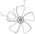
- FIG. 3 and 4 are explanatory views of a conventional axial fan having five blades
- FIG. 3 is a front view of the conventional five blade fan
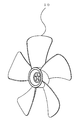
- FIG. 4 is a perspective view of the conventional five blade axial fan.
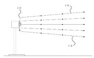
- FIG. 14 is a diagram showing the spread of wind generated when an axial fan with a conventional five-blade is rotated.
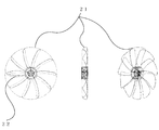
- FIG. 16 is an explanatory diagram of an axial fan when the number of blades is increased while keeping the blade shape of a conventional axial fan unchanged.
- the wind generated from this conventional axial fan is 5 meters away from the front of the axial fan when rotating 30 centimeters of 5 blades at 800 rpm.
- the wind area was 50 cm in diameter, and the wind 19 was almost unexpanded.
- the wind generated from the axial fan has a larger air volume as the blade area is larger when the rotation speed is the same.
- an overlap 22 between the blades when viewed from the front of the axial fan is formed at the base of the blade.
- the problem to be solved by the present invention is that, in the axial fan used for blowing air, although there are many scenes where wind of a larger area is required, the conventional axial fan can provide it.
- the conventional axial fan can provide it.
- the present invention includes a rotating shaft portion attached to a rotating shaft of a rotation driving means such as a motor, an inner blade group provided coaxially with the rotating shaft portion outside the rotating shaft portion, and an outer side of the inner blade group.
- the present invention is concentric with the rotating shaft portion and the rotating shaft in order to enable the manufacture of the upper and lower split molds at the time of injection molding during mass production while increasing the blade area.
- An intermediate ring located between the rotating shaft and the outer periphery of the fan, an inner blade group that reaches the intermediate ring with the rotating shaft as a root, and an outer blade that reaches the outer periphery of the fan with the intermediate ring as a root
- the inner blade group and the outer blade group are different in number, area, shape, and angle, and the inner blade group and the outer blade group have shapes that are not related to each other.
- the blades can be shaped so that the blades do not overlap with each other, and the intermediate ring also leads to an increase in the strength of the entire fan.
- the present invention makes the number of the blades of the inner blade group and the outer blade group different, the area, the shape, and the angle, so that the wind speed generated from the inner blade group when rotating as a fan. And the speed of the wind generated from the outer blade group can be made different.
- the present invention provides a rotating shaft portion, a concentric circle with respect to the rotating shaft, an intermediate ring positioned between the rotating shaft portion and the outer periphery of the fan, and a root coupled to the rotating shaft portion.
- An inner blade that extends in the radial direction when centered, reaches the intermediate ring, and is coupled to the intermediate ring, and a shape in which the inner blade is continuously replicated in the rotational direction when the rotation axis is the center.
- a plurality of outer blade groups each having a shape obtained by continuously replicating the outer blades in the rotation direction with the rotation axis as the center.
- the inner blade and the inner blade group are coupled to the rotation shaft portion with an angle of attack in the rotation direction, and the outer blade and the outer blade group are connected to the intermediate blade.
- the ring is coupled to the ring in the rotational direction with an angle of attack, and the leading edge with respect to the rotational direction of the inner blade and the leading edge with respect to the rotational direction of the outer blade become a non-continuous line when viewed from the front of the fan,
- the trailing edge with respect to the rotation direction of the inner blades and the trailing edge with respect to the rotation direction of the outer blades are not continuous when viewed from the front of the fan, and the inner blade group and the outer blade group are independent from each other. It is characterized by.
- the inner blade group and the outer blade group connected to the intermediate ring can be set to the respective number, area, angle, and shape according to the design intention.
- the angle of attack of the inner blade is ⁇ 1 and the angle of attack of the outer blade is ⁇ 2
- the angle of attack ⁇ 1 and the angle of attack ⁇ 2 have a relationship of ⁇ 1 ⁇ 2 .
- the angle of attack ⁇ 1 is an average angle of attack when the angle of attack of the inner blade is different depending on the location
- the angle of attack ⁇ 2 is when the angle of attack of the outer blade is different depending on the location
- the angle of attack as an average value.
- the area S 1 and the area S 2 are preferably in a relationship of S 1 ⁇ S 2.
- the wind speed V 1 formed by the inner blade group and the wind speed V 2 formed by the outer blade group are preferably in a relationship of 1.5V 1 ⁇ V 2 .
- the intermediate ring has a cross-section that is not plate-like, but an ellipse on the side when the projection view from the viewpoint where the rotation axis of the axial fan and the outer periphery of the fan can be seen concentrically is the front, Other shapes such as a blade cross-section may be used.
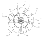
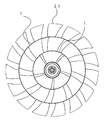
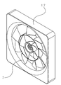
- FIG. 1 and 2 are views showing an axial fan according to the present invention
- FIG. 1 is a front view of the axial fan according to the present invention
- FIG. 2 is a perspective view of the axial fan according to the present invention.
- 3 and 4 are explanatory views of a conventional axial fan having five blades.
- FIG. 14 is a diagram showing the spread of wind generated when an axial fan with a conventional five-blade is rotated.
- FIG. 15 is a diagram showing the spread of wind generated when the axial fan according to the present invention is rotated.
- the wind pushed out inside and outside the intermediate ring 1 when rotated when rotating as a single axial fan 7, the wind speed of the generated wind can be changed between the inner side 11 and the outer side 12 of the intermediate ring 1, and the shaft can be changed.
- a difference in density can be generated in the air pushed out from the inner side 11 and the outer side 12 of the intermediate ring 1 at a close distance portion in front of the flow fan, and thus generated from the inner side 11 and the outer side 12 of the intermediate ring.
- Each wind influences each other, and the effect of being able to change the movement 19 in the direction of the spreading of the wind, which normally spreads slowly, into a movement in a different direction That.
- each of the inner blade 2 group and the outer blade 3 group of the intermediate ring 1 are adjusted according to the design intention, thereby rotating as a single axial fan 7.
- the difference in wind speed generated from each of the inner blade group and the outer blade group of the intermediate ring can be adjusted, and the change in the direction of the wind generated from the front of the axial fan caused by the difference is intentionally changed. There is an effect that it can be adjusted.
- the wind speed V 2 of the wind generated from the outer side 12 of the intermediate ring 1 is determined by the design intention of the number, area, and shape of each of the outer and inner blade groups of the intermediate ring 1.
- the outer side of the intermediate ring 1 is caused by the difference in density generated in the fluid pushed out at the closest distance in front of the rotating axial fan.
- the generated wind is pulled by the low-density wind generated from the inside of the intermediate ring 1, and the movement 19 that normally spreads slowly can be changed to the movement 30 that is wound inwardly and rotates.
- Wind gathers from the front of the axial flow fan for example, at a position 31 at a short distance of several tens of centimeters.
- the recoil gathered in one place then changes to a movement 20 in which the wind is greatly diffused, and at a point away from the front of the rotating axial fan, for example 3 meters, the wind of the conventional axial fan Compared with the spread, there is an effect that it is possible to generate a wind having a large area.
- the present invention by setting the number, area, and shape of the blade groups on the outer and inner sides of the intermediate ring 1 according to the design intention, for example, at a point 3 meters away from the front of the rotating axial fan.
- the effect is that it is possible to generate a large area of wind that is 5 times or more the area of the wind generated when the conventional three- or five-blade axial fan 10 is rotated at the same rotational speed. There is.
- the front edge 32 with respect to the rotation direction 36 of the inner blade 2 and the front edge 33 with respect to the rotation direction 36 of the outer blade 3 are not continuous when viewed from the front, and the inner blade 2 rotates.
- the trailing edge 34 with respect to the direction 36 and the trailing edge 35 with respect to the rotation direction 36 of the outer blade 3 can be a line that is not continuous when viewed from the front, and the inner blade 2 group and the outer blade 3 group can have independent shapes, For example, even when the number of the outer blades 3 group of the intermediate ring 1 is increased and the total outer blade area is increased, the number of the inner blades 2 group of the intermediate ring 1 connected to the rotating shaft can be reduced. There is an effect that it is possible to increase the total blade area of the entire axial fan while eliminating the overlapping of the blades in the vicinity of the rotating shaft and facilitating injection molding at the time of mass production.
- the intermediate ring 1 itself increases the physical strength of the entire axial fan, and even when the total area of the blades of the axial fan is increased, plastic injection molding or the like can be performed. When manufactured by a general mass production method, there is an effect that sufficient strength can be provided.
- each blade group it is not necessary for each blade group to be radially continuous on the inner side and the outer side of the intermediate ring 1 and can be made independent, taking into account the overlapping of the blades, which is a problem during mass production. It is possible to manufacture an axial fan with a larger number of blades and a larger total area of the blades. When this fan is rotated, the conventional three- to five-blade axial fan is rotated at the same rotational speed. There is an effect that it is possible to generate a large amount of wind compared to when it is rotated.
- the number of blades of each blade group can be set on the inner side and the outer side of the intermediate ring 1 without considering the problem of overlapping of the blades at the root portion and insufficient strength after manufacture.
- the number of blades can be remarkably increased. For example, it is said that an axial fan with 5 blades feels gentler than 3 blades. It is possible to generate a wind that can be felt.
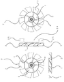
- FIG. 1 is a perspective view of an axial fan and a motor according to the present invention. It is a front view of a conventional 5-blade type axial fan. It is a perspective view of a conventional 5-blade type axial flow fan. It is a trihedral view of the axial fan according to the present invention.
- the purpose is to generate a wide area, large air volume, and gentle wind between the rotating shaft and the outer periphery of the fan.
- FIG. 1 is a front view of an axial fan according to the present invention
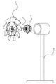
- FIG. 2 is a perspective view of an axial fan and a motor according to the present invention
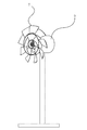
- FIG. 3 is a front view of a conventional five-blade type axial fan
- FIG. 5 is a three-sided view of an axial fan according to the present invention
- FIG. 6 is an explanatory view of a motor for mounting the axial fan and its supporting device
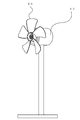
- FIG. FIG. 8 is an explanatory view of a device in which an axial fan according to the present invention is attached to a fan-type motor support device
- FIG. 8 is a diagram showing that a general axial fan composed of five conventional blades is attached to the fan-type motor support device.
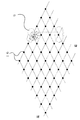
- FIG. 10 are explanatory diagrams of measurement points used when measuring the blowing range of the axial flow fan.
- FIG. 14 is an explanatory diagram showing the spread of the wind generated when the conventional five-blade axial fan is rotated.
- FIG. 15 is a diagram showing the spread of wind generated when the axial fan according to the present invention is rotated.
- reference numeral 1 denotes an intermediate ring which is located between the rotary shaft of the axial fan and the outer periphery of the fan and is concentric with the rotary shaft. In this case, the diameter of the intermediate ring 1 is 17 cm.
- Reference numeral 2 denotes an inner blade of the intermediate ring 1, and the number of blade groups inside the intermediate ring 1 including the blade groups connected thereto is five.
- Reference numeral 3 denotes an outer blade of the intermediate ring 1, and the number of blade groups on the outer side of the intermediate ring 1 including the blade groups connected to the intermediate ring 1 is nine.
- the intermediate ring 1 and the inner blade 2 and the inner blade group connected thereto, the outer blade 3 and the outer blade group connected thereto, and the rotating shaft portion 4 are combined as one plastic molded product, and one axial flow having a diameter of 30 cm. Rotates as fan 7
- the axial fan 7 is set so that the area of each blade is increased in the inner blade 2 group and the outer blade 3 group of the intermediate ring 1 in order to increase the amount of air generated when it rotates. Further, the inner and outer blade groups of the intermediate ring 1 are arranged so as to increase the difference in the wind speed of the wind generated from each of the intermediate ring 1, that is, outside the wind speed V 1 generated from the inner blade 2 group. as the speed V 2 of the wind generated from the group of the blade 3 is increased, the shape and angle of each blade is set.
- the axial flow fan 7 is attached to the motor rotating shaft 6 of the motor 5 and fixed to the device 8 supporting these with screws or the like, and a fan type blower 9 is prepared.
- the axial fan 7 of the blower 9 is rotated at 800 revolutions per minute, and at a distance of 1 centimeter from the front of the axial fan 7, the position becomes a wind generating part from the inner blade 2 and the inner blade group connected thereto. That is, the wind speed is measured at a position 11 moved 4 centimeters from the rotating shaft in the outer peripheral direction of the fan, and the wind speed from the outer blade 3 and the outer blade group connected to the outer blade 3 is combined. When the wind speed was measured even at the position 12 moved 10 cm in the outer circumferential direction, it was as shown in Table 1. In addition, the value of the wind speed uses the average value when measuring continuously for 1 minute at each position.
- a general axial flow fan 10 having a diameter of 30 centimeters composed of five conventional blades is prepared, and this is attached to the motor rotating shaft 6 of the motor 5, and a screw or the like is attached to a device 8 that supports them.
- the fan-type air blower 13 is prepared by fixing by fixing.
- the axial fan 10 of the blower 13 is rotated at 800 revolutions per minute to correspond to Table 1, and moved 1 cm from the front of the axial fan 10 toward the outer periphery of the fan from the rotating shaft.
- the wind speed was measured at the position 14, and the wind speed was also measured at the position 1 to 5 moved 10 cm from the rotating shaft in the outer peripheral direction of the fan.
- the value of the wind speed uses the average value when measuring continuously for 1 minute at each position.
- the axial fan 10 composed of five conventional blades shown in Table 2 has a small difference between the wind speed generated from the vicinity of the outer periphery of the fan and the wind speed generated from the vicinity of the rotating shaft. As shown in FIG. 14, a wind having a gently spreading direction 19 is generated.
- the axis of rotation of the axial fan 7 of the blower 9 is horizontal, its height is 60 cm from the ground, and it is rotated at 800 rpm.
- a mesh-like measurement interval shown in FIG. 9 and FIG. 10 is set in the front direction of the axial fan 7 on the horizontal plane intersecting the rotation axis of the axial fan 7, and indicated by a black dot 16.
- Table 3 the value of the wind speed uses the average value when measuring continuously for 2 minutes at each position.
- the axis of rotation of the axial fan 10 of the blower 13 is horizontal, its height is 60 cm from the ground, and it is rotated at 800 rpm.
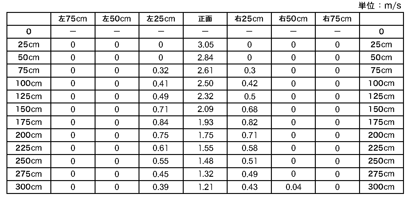
- the measurement conditions were the same as those in Table 3, and the wind speed was measured at each point as shown in Table 4.
- the value of the wind speed uses the average value when measuring continuously for 2 minutes at each position.
- Table 3 which is the wind range of the axial fan 7 according to the present invention
- Table 4 which is the wind range of the axial fan 10 composed of five conventional blades
- the diameter of the axial fan is compared.
- the rotational speed is the same, it can be seen that the axial fan 7 according to the present invention in Table 3 has a larger air blowing range, that is, the area of the generated wind can be increased.
- the wind generated from the axial fan 7 according to the present invention is approximately 1.
- the wind generated by the axial fan 10 composed of five conventional blades is approximately 50 cm in diameter at the same position. Therefore, at a position 3 meters away from the front of the fan, the axial fan 7 according to the present invention has an area about nine times that of the conventional axial fan 10 composed of five blades. It can be seen that the developing wind is generated.
- FIG. 11 is an explanatory diagram of an axial fan when there are a plurality of intermediate rings according to the present invention.
- the intermediate ring 1 may be an axial fan 23 having a plurality of intermediate rings 1 depending on a required air blowing range, a wind spreading direction, and a use, even if the intermediate ring 1 is not single.
- the blade groups on the inner side and the outer side of the intermediate ring 1 bring about an effect such as a change in the air blowing range by increasing the difference in wind speed during rotation.
- the blades 2 inside the intermediate ring 1 may not have a blowing function such as a shaft that connects the intermediate ring and the rotating shaft portion instead of the blade shape.
- the blade groups on the inner side and the outer side of the intermediate ring 1 bring about effects such as a change in the air blowing range by increasing the difference in wind speed during rotation.
- the inner blade 2 group of the intermediate ring 1 may have a blade shape that blows air in the opposite direction to the outer blade 3 group of the intermediate ring 1 when rotated as a single axial fan.
- the diameter of the intermediate ring 1 is increased or decreased between the rotation shaft and the outer periphery of the axial fan depending on the required air blowing range, the wind spreading direction, and the application. It can be set differently.
- FIG. 13 is an explanatory diagram of a heater using an axial fan according to the present invention.
- the axial fan according to the present invention can be used not only for the fan type fan but also for the fan portion of the heater 18 as shown in FIG. It can also be used for the air blowing part of instruments that require
- the fan assembly 11 shown in FIG. 1 described in Japanese Patent Laid-Open No. 10-141285 is rotated at 800 revolutions per minute with the rotation axis being horizontal, its height being 60 cm from the ground.
- the measurement conditions were the same as those in Table 3, and the wind speed was measured at each point as shown in Table 5.
- the value of the wind speed uses the average value when measuring continuously for 2 minutes at each position.
- the fan assembly 11 of FIG. 1 described in Japanese Patent Laid-Open No. 10-141285 has a large gap between the inner blades, and the air from the gap between the inner blades is generated by the early and strong wind formed by the outer blade group. Is sucked in and this air merges with the wind formed by the inner blades to increase the wind speed, so that the speed of the wind formed in the inner blade region and the speed of the wind formed in the outer blade region are The difference is not so large, and even at a point 3 meters away, it is almost 50 cm in diameter, and the wind is not so wide.
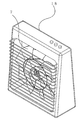
- FIG. 12 is an explanatory diagram in which an axial fan according to the present invention is attached to a ventilation fan
- FIG. 13 is an explanatory diagram of a heater using the axial fan according to the present invention.
- the axial fan according to the present invention is not limited to the use for a fan or a blower, but also a fan such as a ventilation fan 17 as shown in FIG. 12 and a heater 17 as shown in FIG. Of course, it can be used for any device that requires
- the axial fan of the present invention can be used for any device that requires cooling, such as a fan built in a computer, by reducing the outer diameter.
- the axial fan of the present invention can be used for all kinds of equipment and equipment for generating an air flow, for example, an air-conditioning fan function part of a building facility, etc. by increasing the outer diameter. .
- the axial fan of the present invention is not limited to the target for generating a flow, but can be any fluid such as a gas or a liquid.
- a screw that rotates in water flows into the fluid can be used for any device for generating
Landscapes
- Engineering & Computer Science (AREA)
- Mechanical Engineering (AREA)
- General Engineering & Computer Science (AREA)
- Structures Of Non-Positive Displacement Pumps (AREA)
- Wind Motors (AREA)
Abstract
Description


2 中間リングの内側の羽根
3 中間リングの外側の羽根
4 軸流ファンの回転軸部
5 モーター
6 モーターの回転軸
7 本発明に係る軸流ファン
8 モーターの支持装置
9 本発明に係る軸流ファンを取り付けた扇風機型の送風装置
10 従来型の5枚の羽根で構成される一般的な軸流ファン
11 風速計測ポイント
12 風速計測ポイント
13 従来型の5枚の羽根で構成される一般的な軸流ファンを取り付けた扇風機型の送風装置
14 風速計測ポイント
15 風速計測ポイント
16 風速計測ポイント
17 本発明に係る軸流ファンを取り付けた換気扇型の送風装置
18 本発明に係る軸流ファンを送風機能部に取り付けた暖房装置
19 従来型の5枚の羽根の軸流ファンを回転させた時の風の広がり
20 本発明に係る軸流ファンを回転させた時の風の広がり
21 従来型の5枚羽根を羽根の形状をそのままに10枚はねとした場合の軸流ファン
22 正面から見た時に羽根同士が重なる部分
23 中間リングを複数とした本発明に係る軸流ファン
24 本発明に係る軸流ファン正面の至近距離位置の軸付近空間
25 本発明に係る軸流ファン正面の至近距離位置の外周付近空間
30 本発明に係る軸流ファンを回転させた時の近距離における風の方向
31 本発明に係る軸流ファンを回転させた時の風が集まる位置
Claims (6)
- 回転駆動手段の回転軸に取り付けられる回転軸部と、該回転軸部の外側に該回転軸部と同軸に設けられた内側羽根群と、該内側羽根群の外側に該内側羽根群と同軸に設けられた外側羽根群とを備え、該内側羽根群は該回転軸部を中心にして放射状に設けられた複数の内側羽根からなり、該外側羽根群は該回転軸部を中心にして放射状に設けられた複数の外側羽根からなり、該内側羽根群によって形成される風の速度V1と該外側羽根群によって形成される風の速度V2が、1.5V1<V2の関係にあることを特徴とする軸流ファン。
- 前記内側羽根及び前記外側羽根は回転方向に対して迎え角を有し、該内側羽根の迎え角をα1、該外側羽根の迎え角をα2としたとき、該迎え角α1と該迎え角α2が、α1<α2の関係にあることを特徴とする請求項1に記載の軸流ファン。
- 前記内側羽根の合計面積をS1、前記外側羽根の合計面積をS2としたとき、該面積S1と該面積S2が、S1<S2の関係にあることを特徴とする請求項1又は2に記載の軸流ファン。
- 前記外側羽根群は中間リングを介して前記内側羽根群の外側に設けられていることを特徴とする請求項1~3のいずれかに記載の軸流ファン。
- 軸流ファンを正面から見た時の前記内側羽根群の隣り合う内側羽根間の隙間の合計面積Sgが前記内側羽根の合計面積S1との関係で、Sg<0.12S1の関係にあることを特徴とする請求項1~4のいずれかに記載の軸流ファン。
- 前記内側羽根の回転方向に対する前縁と前記外側羽根の回転方向に対する前縁がファン正面から見た時に連続しない線となり、前記内側羽根の回転方向に対する後縁と前記外側羽根の回転方向に対する後縁がファン正面から見た時に連続しない線となることを特徴とする請求項1~5のいずれかに記載の軸流ファン。
Priority Applications (11)
| Application Number | Priority Date | Filing Date | Title |
|---|---|---|---|
| SG2011096534A SG177386A1 (en) | 2009-06-28 | 2010-06-24 | Axial fan |
| AU2010267210A AU2010267210B2 (en) | 2009-06-28 | 2010-06-24 | Axial fan |
| CN201080003301.XA CN102227562B (zh) | 2009-06-28 | 2010-06-24 | 轴流风扇 |
| EP10794059.5A EP2469101B1 (en) | 2009-06-28 | 2010-06-24 | Axial fan |
| ES10794059.5T ES2505291T3 (es) | 2009-06-28 | 2010-06-24 | Ventilador axial |
| JP2011520884A JP4949537B2 (ja) | 2009-06-28 | 2010-06-24 | 軸流ファン |
| CA2760653A CA2760653C (en) | 2009-06-28 | 2010-06-24 | Axial flow fan |
| KR1020117028040A KR101196493B1 (ko) | 2009-06-28 | 2010-06-24 | 축류팬 |
| BRPI1012266A BRPI1012266A2 (pt) | 2009-06-28 | 2010-06-24 | ventilador de fluxo axial. |
| HK12103941.0A HK1163779B (en) | 2009-06-28 | 2010-06-24 | Axial fan |
| US13/288,526 US8535010B2 (en) | 2009-06-28 | 2011-11-03 | Axial flow fan |
Applications Claiming Priority (2)
| Application Number | Priority Date | Filing Date | Title |
|---|---|---|---|
| JP2009-169502 | 2009-06-28 | ||
| JP2009169502 | 2009-06-28 |
Related Child Applications (1)
| Application Number | Title | Priority Date | Filing Date |
|---|---|---|---|
| US13/288,526 Continuation US8535010B2 (en) | 2009-06-28 | 2011-11-03 | Axial flow fan |
Publications (1)
| Publication Number | Publication Date |
|---|---|
| WO2011001890A1 true WO2011001890A1 (ja) | 2011-01-06 |
Family
ID=43410965
Family Applications (1)
| Application Number | Title | Priority Date | Filing Date |
|---|---|---|---|
| PCT/JP2010/060746 Ceased WO2011001890A1 (ja) | 2009-06-28 | 2010-06-24 | 軸流ファン |
Country Status (12)
| Country | Link |
|---|---|
| US (1) | US8535010B2 (ja) |
| EP (1) | EP2469101B1 (ja) |
| JP (4) | JP4949537B2 (ja) |
| KR (2) | KR20120096072A (ja) |
| CN (1) | CN102227562B (ja) |
| AU (1) | AU2010267210B2 (ja) |
| BR (1) | BRPI1012266A2 (ja) |
| CA (1) | CA2760653C (ja) |
| ES (1) | ES2505291T3 (ja) |
| MY (1) | MY155880A (ja) |
| SG (1) | SG177386A1 (ja) |
| WO (1) | WO2011001890A1 (ja) |
Cited By (7)
| Publication number | Priority date | Publication date | Assignee | Title |
|---|---|---|---|---|
| EP3406912A1 (en) | 2017-05-22 | 2018-11-28 | Fujitsu General Limited | Propeller fan |
| WO2019111973A1 (ja) | 2017-12-05 | 2019-06-13 | 株式会社富士通ゼネラル | プロペラファン |
| US11293452B2 (en) | 2018-11-30 | 2022-04-05 | Fujitsu General Limited | Propeller fan |
| US11313382B2 (en) | 2018-11-30 | 2022-04-26 | Fujitsu General Limited | Propeller fan |
| US11313377B2 (en) | 2018-11-30 | 2022-04-26 | Fujitsu General Limited | Propeller fan |
| US11512710B2 (en) | 2018-11-30 | 2022-11-29 | Fujitsu General Limited | Propeller fan |
| US11536288B2 (en) | 2018-03-22 | 2022-12-27 | Fujitsu General Limited | Propeller fan |
Families Citing this family (42)
| Publication number | Priority date | Publication date | Assignee | Title |
|---|---|---|---|---|
| CA2755521A1 (en) * | 2009-04-29 | 2010-09-23 | Shamel A. Bersiek | Wind jet turbine ii |
| TWI476327B (zh) * | 2012-09-12 | 2015-03-11 | 張菀茹 | 適用於風扇的雙層扇葉結構 |
| CN103016371B (zh) * | 2012-12-03 | 2015-09-16 | 浙江泰达微电机有限公司 | 一种轴流风扇 |
| CN104033408B (zh) * | 2013-03-06 | 2016-12-28 | 福州斯狄渢电热水器有限公司 | 一种可取暖的双风叶风扇 |
| KR101598430B1 (ko) * | 2014-04-29 | 2016-03-14 | 김형기 | 헤어드라이어 |
| KR20150133077A (ko) * | 2014-05-19 | 2015-11-27 | 엘지전자 주식회사 | 송풍팬 및 이를 적용한 공기조화기 |
| CN105240316A (zh) * | 2015-10-10 | 2016-01-13 | 珠海格力电器股份有限公司 | 轴流风叶、轴流风机和空调器 |
| KR101720644B1 (ko) | 2016-01-21 | 2017-03-28 | 오텍캐리어 주식회사 | 윙렛 구조를 가지는 이중팬 및 이러한 이중팬을 구비하는 공기조화기 |
| WO2017128803A1 (zh) * | 2016-01-27 | 2017-08-03 | 广东美的环境电器制造有限公司 | 风轮及家用电器 |
| CN106930974B (zh) * | 2016-01-27 | 2023-02-17 | 广东美的环境电器制造有限公司 | 风轮及家用电器 |
| JP2019504958A (ja) * | 2016-01-27 | 2019-02-21 | 広東美的環境電器制造有限公司 | ファン及び家電機器 |
| CN105952669A (zh) * | 2016-04-18 | 2016-09-21 | 浙江久友电器科技有限公司 | 具有双风道的风叶组件 |
| KR101828905B1 (ko) | 2016-07-20 | 2018-03-29 | 엘지전자 주식회사 | 송풍기 |
| JP6745902B2 (ja) * | 2016-11-25 | 2020-08-26 | 三菱電機株式会社 | 送風機、室外機及び冷凍サイクル装置 |
| CN106762823A (zh) * | 2016-12-28 | 2017-05-31 | 东莞市卓奇电子科技有限公司 | 多流道轴流风聚焦叶轮 |
| CN106762828A (zh) * | 2017-01-19 | 2017-05-31 | 梁耀文 | 风机扇叶环形多级叶片结构 |
| CN106762829B (zh) * | 2017-02-07 | 2023-10-31 | 珠海格力电器股份有限公司 | 用于叶轮的叶片、叶轮及风机 |
| KR102404660B1 (ko) | 2017-09-01 | 2022-06-02 | 엘지전자 주식회사 | 유동 발생장치 |
| KR102281749B1 (ko) | 2017-09-01 | 2021-07-26 | 엘지전자 주식회사 | 유동 발생장치 |
| KR102407570B1 (ko) | 2017-09-01 | 2022-06-10 | 엘지전자 주식회사 | 유동 발생장치 |
| KR102404689B1 (ko) | 2017-09-01 | 2022-06-07 | 엘지전자 주식회사 | 유동 발생장치 |
| KR102037704B1 (ko) | 2018-05-16 | 2019-10-29 | 엘지전자 주식회사 | 유동 발생장치 |
| GB201813674D0 (en) | 2018-08-22 | 2018-10-03 | Rolls Royce Plc | Turbomachine |
| GB201813672D0 (en) | 2018-08-22 | 2018-10-03 | Rolls Royce Plc | Turbomachine |
| GB201813675D0 (en) | 2018-08-22 | 2018-10-03 | Rolls Royce Plc | Turbomachine |
| GB201813671D0 (en) | 2018-08-22 | 2018-10-03 | Rolls Royce Plc | Turbomachine |
| GB201813670D0 (en) | 2018-08-22 | 2018-10-03 | Rolls Royce Plc | Turbomachine |
| KR102615039B1 (ko) | 2018-08-24 | 2023-12-19 | 삼성전자주식회사 | 공기조화기 및 가전제품 |
| CN109210745A (zh) * | 2018-10-09 | 2019-01-15 | 珠海格力电器股份有限公司 | 一种空调出风装置与空调及控制方法 |
| CN111043057B (zh) | 2018-10-15 | 2022-03-25 | 广东美的白色家电技术创新中心有限公司 | 对旋风扇 |
| CN111043063B (zh) | 2018-10-15 | 2021-06-18 | 广东美的白色家电技术创新中心有限公司 | 对旋风扇 |
| CN110645649B (zh) * | 2019-09-17 | 2022-06-07 | 吴嵘 | 一种空气灭菌除尘装置 |
| CN110848173B (zh) * | 2019-12-18 | 2024-10-18 | 珠海格力电器股份有限公司 | 送风装置 |
| CN112090204B (zh) * | 2020-08-11 | 2022-08-23 | 安徽龙钰徽派古建工艺制品有限公司 | 一种具有粉尘收集功能的砖瓦生产用切割设备 |
| CN112012959B (zh) * | 2020-09-27 | 2021-12-31 | 北京航天奥祥通风科技股份有限公司 | 轴流叶轮及风机 |
| CN112220367B (zh) * | 2020-09-30 | 2022-03-18 | 宁波方太厨具有限公司 | 一种用于烹饪设备的扇叶结构及具有该结构的烤箱 |
| CN112594212A (zh) * | 2020-12-09 | 2021-04-02 | 江苏美的清洁电器股份有限公司 | 一种叶轮、风机及吸尘器 |
| CN114233680A (zh) | 2021-12-29 | 2022-03-25 | 续新电器技术(深圳)有限公司 | 组合式扇叶及组合出风装置 |
| KR102913436B1 (ko) * | 2023-02-14 | 2026-01-15 | 이승무 | 바람의 직진성이 향상된 회전 날개 |
| KR102808460B1 (ko) * | 2023-02-20 | 2025-05-19 | 주식회사 보국전자 | 자연바람 생성을 위한 이중날개와 그릴각도를 최적화한 에어 서큘레이터 |
| JPWO2024247207A1 (ja) * | 2023-06-01 | 2024-12-05 | ||
| CZ310397B6 (cs) * | 2023-10-24 | 2025-05-07 | Radislav Ing Krupa | Axiální ventilátor |
Citations (7)
| Publication number | Priority date | Publication date | Assignee | Title |
|---|---|---|---|---|
| JPS58156117U (ja) * | 1982-04-14 | 1983-10-18 | 日産自動車株式会社 | 自動車用冷却フアン |
| JPH10141285A (ja) | 1996-11-13 | 1998-05-26 | Eaton Corp | ファン組立体 |
| JPH10205330A (ja) * | 1997-01-21 | 1998-08-04 | Nissan Motor Co Ltd | 冷却ファン |
| JP2000120590A (ja) | 1998-05-06 | 2000-04-25 | Eaton Corp | ファン組立体 |
| JP2002221191A (ja) | 2001-01-22 | 2002-08-09 | Kurako:Kk | ファン装置 |
| JP2003120588A (ja) * | 2001-10-18 | 2003-04-23 | Denso Corp | 送風装置 |
| JP2004060447A (ja) | 2002-07-24 | 2004-02-26 | Sanden Corp | 多翼ファン |
Family Cites Families (16)
| Publication number | Priority date | Publication date | Assignee | Title |
|---|---|---|---|---|
| JPS58156117A (ja) | 1982-03-11 | 1983-09-17 | Rinnai Corp | ガスバ−ナへの燃料ガス供給量の調節機構 |
| JPS59183099A (ja) * | 1983-03-31 | 1984-10-18 | Nippon Denso Co Ltd | 軸流フアン |
| JPS6348997U (ja) * | 1986-09-17 | 1988-04-02 | ||
| JP2958008B2 (ja) * | 1988-07-08 | 1999-10-06 | ティーディーケイ株式会社 | 圧電ブザーの製造方法 |
| CN2040555U (zh) * | 1988-04-25 | 1989-07-05 | 陈天材 | 广角可调风扇 |
| JPH0222698U (ja) * | 1988-07-28 | 1990-02-15 | ||
| US5193983A (en) * | 1991-08-05 | 1993-03-16 | Norm Pacific Automation Corp. | Axial-flow fan-blade with profiled guide fins |
| JPH05106592A (ja) * | 1991-10-18 | 1993-04-27 | Toshiba Corp | 空気調和機用軸流フアン |
| US5755557A (en) * | 1995-08-03 | 1998-05-26 | Valeo Thermique Moteur | Axial flow fan |
| US5860788A (en) * | 1996-06-14 | 1999-01-19 | Shell Electric Mfg. (Holdings) Co. Ltd. | Low drag fan assembly |
| EP0953774A1 (en) * | 1998-04-01 | 1999-11-03 | Eaton Corporation | Fan assembly having increased fan blade area |
| JP4483148B2 (ja) * | 2001-08-29 | 2010-06-16 | ダイキン工業株式会社 | 軸流ファン用羽根車 |
| KR100546650B1 (ko) * | 2003-06-04 | 2006-01-26 | 엘지전자 주식회사 | 송풍기 |
| JP2006207379A (ja) * | 2005-01-25 | 2006-08-10 | Calsonic Kansei Corp | 送風ファン |
| CN101149063A (zh) * | 2006-09-22 | 2008-03-26 | 乐金电子(天津)电器有限公司 | 一体式空调器轴流风扇结构 |
| US8342808B2 (en) * | 2006-12-11 | 2013-01-01 | Mitsuba Corporation | Cooling fan |
-
2010
- 2010-06-24 KR KR1020127017858A patent/KR20120096072A/ko not_active Withdrawn
- 2010-06-24 KR KR1020117028040A patent/KR101196493B1/ko active Active
- 2010-06-24 JP JP2011520884A patent/JP4949537B2/ja active Active
- 2010-06-24 AU AU2010267210A patent/AU2010267210B2/en active Active
- 2010-06-24 MY MYPI2011005270A patent/MY155880A/en unknown
- 2010-06-24 CA CA2760653A patent/CA2760653C/en active Active
- 2010-06-24 BR BRPI1012266A patent/BRPI1012266A2/pt not_active Application Discontinuation
- 2010-06-24 WO PCT/JP2010/060746 patent/WO2011001890A1/ja not_active Ceased
- 2010-06-24 SG SG2011096534A patent/SG177386A1/en unknown
- 2010-06-24 EP EP10794059.5A patent/EP2469101B1/en active Active
- 2010-06-24 ES ES10794059.5T patent/ES2505291T3/es active Active
- 2010-06-24 CN CN201080003301.XA patent/CN102227562B/zh active Active
-
2011
- 2011-08-24 JP JP2011183074A patent/JP5916319B2/ja active Active
- 2011-11-03 US US13/288,526 patent/US8535010B2/en active Active
-
2014
- 2014-08-04 JP JP2014158709A patent/JP5873148B2/ja active Active
- 2014-08-04 JP JP2014158710A patent/JP6043761B2/ja active Active
Patent Citations (7)
| Publication number | Priority date | Publication date | Assignee | Title |
|---|---|---|---|---|
| JPS58156117U (ja) * | 1982-04-14 | 1983-10-18 | 日産自動車株式会社 | 自動車用冷却フアン |
| JPH10141285A (ja) | 1996-11-13 | 1998-05-26 | Eaton Corp | ファン組立体 |
| JPH10205330A (ja) * | 1997-01-21 | 1998-08-04 | Nissan Motor Co Ltd | 冷却ファン |
| JP2000120590A (ja) | 1998-05-06 | 2000-04-25 | Eaton Corp | ファン組立体 |
| JP2002221191A (ja) | 2001-01-22 | 2002-08-09 | Kurako:Kk | ファン装置 |
| JP2003120588A (ja) * | 2001-10-18 | 2003-04-23 | Denso Corp | 送風装置 |
| JP2004060447A (ja) | 2002-07-24 | 2004-02-26 | Sanden Corp | 多翼ファン |
Non-Patent Citations (1)
| Title |
|---|
| See also references of EP2469101A4 |
Cited By (10)
| Publication number | Priority date | Publication date | Assignee | Title |
|---|---|---|---|---|
| EP3406912A1 (en) | 2017-05-22 | 2018-11-28 | Fujitsu General Limited | Propeller fan |
| CN108930666A (zh) * | 2017-05-22 | 2018-12-04 | 富士通将军股份有限公司 | 螺旋桨式风机 |
| US11391295B2 (en) | 2017-05-22 | 2022-07-19 | Fujitsu General Limited | Propeller fan |
| WO2019111973A1 (ja) | 2017-12-05 | 2019-06-13 | 株式会社富士通ゼネラル | プロペラファン |
| US11187237B2 (en) | 2017-12-05 | 2021-11-30 | Fujitsu General Limited | Propeller fan |
| US11536288B2 (en) | 2018-03-22 | 2022-12-27 | Fujitsu General Limited | Propeller fan |
| US11293452B2 (en) | 2018-11-30 | 2022-04-05 | Fujitsu General Limited | Propeller fan |
| US11313382B2 (en) | 2018-11-30 | 2022-04-26 | Fujitsu General Limited | Propeller fan |
| US11313377B2 (en) | 2018-11-30 | 2022-04-26 | Fujitsu General Limited | Propeller fan |
| US11512710B2 (en) | 2018-11-30 | 2022-11-29 | Fujitsu General Limited | Propeller fan |
Also Published As
| Publication number | Publication date |
|---|---|
| JP5873148B2 (ja) | 2016-03-01 |
| KR101196493B1 (ko) | 2012-11-01 |
| JP2014224540A (ja) | 2014-12-04 |
| JP2011256876A (ja) | 2011-12-22 |
| BRPI1012266A2 (pt) | 2016-04-05 |
| CN102227562B (zh) | 2015-04-22 |
| HK1163779A1 (en) | 2012-09-14 |
| CA2760653C (en) | 2015-02-24 |
| CA2760653A1 (en) | 2011-01-06 |
| KR20120096072A (ko) | 2012-08-29 |
| JP4949537B2 (ja) | 2012-06-13 |
| JPWO2011001890A1 (ja) | 2012-12-13 |
| EP2469101B1 (en) | 2014-08-13 |
| SG177386A1 (en) | 2012-02-28 |
| EP2469101A1 (en) | 2012-06-27 |
| US20120107092A1 (en) | 2012-05-03 |
| AU2010267210A1 (en) | 2011-12-08 |
| EP2469101A4 (en) | 2013-05-01 |
| JP5916319B2 (ja) | 2016-05-11 |
| MY155880A (en) | 2015-12-15 |
| JP2015007429A (ja) | 2015-01-15 |
| JP6043761B2 (ja) | 2016-12-14 |
| CN102227562A (zh) | 2011-10-26 |
| KR20120049182A (ko) | 2012-05-16 |
| ES2505291T3 (es) | 2014-10-09 |
| US8535010B2 (en) | 2013-09-17 |
| AU2010267210B2 (en) | 2015-11-05 |
Similar Documents
| Publication | Publication Date | Title |
|---|---|---|
| JP5873148B2 (ja) | 軸流ファン | |
| KR200472965Y1 (ko) | 선풍기 | |
| CN112628165B (zh) | 风扇及其风扇叶轮 | |
| TWI418708B (zh) | 葉輪結構 | |
| WO2020147313A1 (zh) | 吊顶式空调室内机 | |
| KR20130111458A (ko) | 축류팬 | |
| CN106122090A (zh) | 轴流风轮和轴流风机 | |
| CN202360431U (zh) | 可防止扇轮脱出的风扇 | |
| CN210014450U (zh) | 吊顶式空调室内机 | |
| CN207501277U (zh) | 天花机 | |
| CN216867058U (zh) | 进风圈组件、离心风机及油烟机 | |
| CN219865578U (zh) | 离心风机及空调器 | |
| CN206017259U (zh) | 一种风机叶轮及其风机盘管 | |
| JP2021092215A (ja) | 受風板付水平軸風車 | |
| CN208382403U (zh) | 空调室外机 | |
| CN221664950U (zh) | 风扇 | |
| CN202811530U (zh) | 风扇的涡旋气流产生器 | |
| CN215909148U (zh) | 预旋组件、风机系统及吸油烟机 | |
| CN211343417U (zh) | 一种对旋式管道通风装置 | |
| CN206206216U (zh) | 一种散热风扇 | |
| CN107883447A (zh) | 天花机 | |
| CN108730231B (zh) | 一种风叶的比例设计方法 | |
| RU52281U1 (ru) | Центробежный вентилятор электрической машины | |
| HK1163779B (en) | Axial fan | |
| KR20140001808U (ko) | 선풍기 |
Legal Events
| Date | Code | Title | Description |
|---|---|---|---|
| WWE | Wipo information: entry into national phase |
Ref document number: 201080003301.X Country of ref document: CN |
|
| ENP | Entry into the national phase |
Ref document number: 2011520884 Country of ref document: JP Kind code of ref document: A |
|
| 121 | Ep: the epo has been informed by wipo that ep was designated in this application |
Ref document number: 10794059 Country of ref document: EP Kind code of ref document: A1 |
|
| WWE | Wipo information: entry into national phase |
Ref document number: 2760653 Country of ref document: CA |
|
| WWE | Wipo information: entry into national phase |
Ref document number: 2010267210 Country of ref document: AU |
|
| ENP | Entry into the national phase |
Ref document number: 20117028040 Country of ref document: KR Kind code of ref document: A |
|
| ENP | Entry into the national phase |
Ref document number: 2010267210 Country of ref document: AU Date of ref document: 20100624 Kind code of ref document: A |
|
| WWE | Wipo information: entry into national phase |
Ref document number: 5136/KOLNP/2011 Country of ref document: IN |
|
| NENP | Non-entry into the national phase |
Ref country code: DE |
|
| WWE | Wipo information: entry into national phase |
Ref document number: 2010794059 Country of ref document: EP |
|
| REG | Reference to national code |
Ref country code: BR Ref legal event code: B01A Ref document number: PI1012266 Country of ref document: BR |
|
| ENP | Entry into the national phase |
Ref document number: PI1012266 Country of ref document: BR Kind code of ref document: A2 Effective date: 20111227 |