WO2011001703A1 - 伸線装置及び素線の製造方法 - Google Patents
伸線装置及び素線の製造方法 Download PDFInfo
- Publication number
- WO2011001703A1 WO2011001703A1 PCT/JP2010/052240 JP2010052240W WO2011001703A1 WO 2011001703 A1 WO2011001703 A1 WO 2011001703A1 JP 2010052240 W JP2010052240 W JP 2010052240W WO 2011001703 A1 WO2011001703 A1 WO 2011001703A1
- Authority
- WO
- WIPO (PCT)
- Prior art keywords
- wire
- capstans
- capstan
- diameter
- take
- Prior art date
- Legal status (The legal status is an assumption and is not a legal conclusion. Google has not performed a legal analysis and makes no representation as to the accuracy of the status listed.)
- Ceased
Links
Images



Classifications
-
- B—PERFORMING OPERATIONS; TRANSPORTING
- B21—MECHANICAL METAL-WORKING WITHOUT ESSENTIALLY REMOVING MATERIAL; PUNCHING METAL
- B21C—MANUFACTURE OF METAL SHEETS, WIRE, RODS, TUBES, PROFILES OR LIKE SEMI-MANUFACTURED PRODUCTS OTHERWISE THAN BY ROLLING; AUXILIARY OPERATIONS USED IN CONNECTION WITH METAL-WORKING WITHOUT ESSENTIALLY REMOVING MATERIAL
- B21C1/00—Manufacture of metal sheets, wire, rods, tubes or like semi-manufactured products by drawing
- B21C1/02—Drawing metal wire or like flexible metallic material by drawing machines or apparatus in which the drawing action is effected by drums
- B21C1/04—Drawing metal wire or like flexible metallic material by drawing machines or apparatus in which the drawing action is effected by drums with two or more dies operating in series
-
- B—PERFORMING OPERATIONS; TRANSPORTING
- B21—MECHANICAL METAL-WORKING WITHOUT ESSENTIALLY REMOVING MATERIAL; PUNCHING METAL
- B21C—MANUFACTURE OF METAL SHEETS, WIRE, RODS, TUBES, PROFILES OR LIKE SEMI-MANUFACTURED PRODUCTS OTHERWISE THAN BY ROLLING; AUXILIARY OPERATIONS USED IN CONNECTION WITH METAL-WORKING WITHOUT ESSENTIALLY REMOVING MATERIAL
- B21C1/00—Manufacture of metal sheets, wire, rods, tubes or like semi-manufactured products by drawing
- B21C1/02—Drawing metal wire or like flexible metallic material by drawing machines or apparatus in which the drawing action is effected by drums
- B21C1/12—Regulating or controlling speed of drawing drums, e.g. to influence tension; Drives; Stop or relief mechanisms
Definitions
- This invention relates to a technique for drawing a wire.
- Patent Document 1 Conventionally, as a technique for drawing a wire, there are those disclosed in Patent Document 1 and Patent Document 2.
- Patent Document 1 a plurality of intermediate extraction capstans are divided into two or more blocks so that a plurality of intermediate extraction capstans are contained in one block, and a plurality of intermediate extraction capstans are provided by one drive motor for each block. The pulling capstan is driven.
- Patent Document 2 a plurality of wire drawing units having a drive capstan and a capstan drive motor are disposed between the unwinding means and the winding means.
- the degree of diameter reduction deformation of the wire is set corresponding to each capstan, and the wire is gradually reduced in diameter through a plurality of diameter reduction deformation processes. Yes. Specifically, dies corresponding to the degree of diameter reduction deformation are disposed between the capstans. Further, the pulling speed ratio of the capstan disposed so as to sandwich the die is set according to the degree of diameter reduction deformation by each die.
- the present invention makes it possible to easily cope with an adjustment change of the degree of diameter reduction deformation of the wire according to the material of the bus wire, the target finished wire diameter, etc. while simplifying the maintenance work. With the goal.
- a first aspect is a wire drawing device for drawing a wire material, the wire material supply unit for supplying the wire material, a wire material take-up unit for taking up the wire material, and a plurality of first capstans.
- a first rotation drive source; and a first rotation transmission mechanism that transmits a rotation drive force of the first rotation drive source to the plurality of first capstans, the wire supply unit and the wire take-up A plurality of second capstans, a plurality of second capstans, and a plurality of second capstans individually driven to rotate.
- the second capstan mechanism part provided between the wire supply part and the wire take-up part and closer to the wire take-up part than the first capstan mechanism part;
- a plurality of first capstans and the plurality of second capstans And a die plurality disposed between each, are those comprising a.
- a 2nd aspect is a wire drawing apparatus which concerns on a 1st aspect, Comprising:
- the diameter of the wire at the time of passing through all the said 2nd capstan is among the several types of finishing wire diameters used as manufacture object It becomes the finest finished wire diameter, and the diameter of the wire when passing through a part of the plurality of second capstans is one finished wire diameter of a plurality of kinds of finished wire diameters to be manufactured. In this way, a drawing speed ratio before and after the plurality of second capstans is set.
- a 3rd aspect is a wire drawing apparatus which concerns on a 1st or 2nd aspect, Comprising: The drawing speed ratio between front and rear with respect to each of these 2nd capstans becomes small gradually toward the said wire material take-up part side. It is set to be.
- a fourth aspect is a wire drawing apparatus according to any one of the first to third aspects, wherein the wire material to be drawn is an aluminum wire or an aluminum alloy wire, and has a diameter of 0.5 mm or less.
- the drawing speed ratio between the plurality of first capstans is set so that the wire drawing process is performed while drawing the wire with the second capstan.
- a fifth aspect is a wire drawing apparatus according to any one of the first to fourth aspects, wherein at least one finishing capstan, one finishing rotary drive source, and the finishing rotary drive source are provided.
- a finishing capstan mechanism portion provided on the portion side is further provided.
- a 6th aspect is a strand manufacturing method which manufactures a strand by drawing a wire, Comprising: The wire supply part which supplies a wire, the wire take-up part which takes up a wire, and a plurality of 1st caps A stun, one first rotation drive source, and a first rotation transmission mechanism that transmits a rotation drive force of the first rotation drive source to the plurality of first capstans, and the wire supply unit and the A plurality of second capstans, a plurality of second capstans, and a plurality of second capstans that are individually driven to rotate between a wire rod take-up unit and the wire rod supply unit side
- the diameter of the wire rod when passing through all the plurality of second capstans is the finest finished wire diameter among the plurality of types of finished wire
- the plurality of second capstans are arranged such that the diameter of the wire when passing through a part of the plurality of second capstans is one finished wire diameter among a plurality of kinds of finished wire diameters to be manufactured.
- the rotational driving force of one first rotational drive source is transmitted to the plurality of first capstans via the first rotational transmission mechanism. Therefore, the maintenance work can be facilitated.
- the rotational speeds of the plurality of second rotation sources are individually adjusted to change the rotational speeds of the plurality of second capstans, so that the front and rear of each second capstan The drawing speed ratio can be changed with. For this reason, it is possible to easily cope with an adjustment change of the degree of diameter reduction deformation of the wire rod according to the material of the bus wire, the finished finished wire diameter, and the like.
- a wire having a small diameter can be manufactured by performing wire drawing using all of the plurality of second capstans. And if a wire drawing is performed by a part of several 2nd capstan, the strand which is one of the multiple types of finishing wire diameter used as manufacture object can be manufactured. For this reason, once the drawing speed ratio before and after the second capstan is set, it is possible to easily produce wire drawing having a plurality of types of finished wire diameters without changing the drawing speed ratio.
- the drawing speed ratio between the front and rear becomes smaller, so that the wire can be more reliably prevented from being cut.
- an aluminum wire or an aluminum alloy wire is difficult to cut with a diameter larger than 0.50 mm and easy to cut with a diameter smaller than 0.50 mm during wire drawing. Therefore, as in the fourth aspect, by performing wire drawing until the diameter reaches about 0.50 mm in the first capstan mechanism portion, efficient wire drawing with a fixed feed speed ratio can be performed. On the other hand, by drawing the second capstan to draw a wire having a diameter of 0.50 mm or less, the drawing speed is adjusted so that the aluminum wire or the aluminum alloy wire is difficult to cut. Yes.
- the first capstan mechanism portion performs wire drawing with a relatively large diameter reduction degree of deformation
- the second capstan mechanism portion extends with a diameter reduction degree of deformation adjusted according to the material and the like.
- Wire drawing can be performed with a plurality of capstans for finishing with a degree of diameter reduction suitable for finishing.
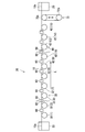
- FIG. 1 is a schematic plan view showing a wire drawing device 20 according to the embodiment
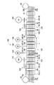
- FIG. 2 is a schematic side view showing the wire drawing device 20.
- the wire drawing device 20 is a device for drawing the wire 10 so that the diameter of the wire 10 is reduced.
- the wire 10 is a general term including all before and after the wire drawing process and during the wire process, and the wire before the process may be distinguished from the bus wire 10a and the wire drawn after the process may be distinguished from the wire 10b. .
- the strand 10b is used alone or in a twisted form as a core wire of an electric wire.
- the wire rod supply unit 22 is configured to be able to supply the bus wire 10a. More specifically, the wire supply part 22 is configured such that the bus wire 10a is wound and accommodated on a reel-shaped member. The wire rod supply unit 22 is rotatably supported on the upstream side of a predetermined wire drawing line L, and the bus wire 10a can be drawn from the wire rod supply unit 22.
- the wire rod take-up section 26 is configured to take up the wire 10b. More specifically, in the wire take-up section 26, a reel-like member capable of winding and housing the wire 10b is supported so as to be rotationally driven by a rotational drive source such as a motor. The wire take-up section 26 is disposed downstream of the wire drawing line L so that the wire 10b processed to the final finished wire diameter is taken up and accommodated by the main wire take-up section 26. It has become.
- wire rod supply units 22 and wire rod take-up units 26 are provided so as to enable a wire drawing process on a plurality (here, seven) of bus wires 10a.
- the twisting mechanism part which twists the some strand 10b in the downstream of the 2nd capstan mechanism part 40 may be provided.
- only one wire rod take-up portion that takes only one stranded wire may be provided.
- the first capstan mechanism portion 30 is provided between the wire rod supply portion 22 and the wire rod take-up portion 26 and on the wire rod supply portion 22 side, and a plurality of (here, eight) first capstans 32 (1 ), 32 (2),..., 32 (6), 32 (7), 32 (8), one first rotation drive source 34, and a first rotation transmission mechanism 36. .
- Each of the first capstans 32 (1), 32 (2), ..., 32 (6), 32 (7), 32 (8) is formed in a substantially disc shape or a substantially cylindrical shape, A circumferential groove around which the wire 10 can be wound is formed on the outer periphery. The circumferential grooves are formed according to the number of the wires 10 to be processed. Here, seven circumferential grooves are formed.
- Each of the first capstans 32 (1), 32 (2), ..., 32 (6), 32 (7), 32 (8) is drawn in this order from the upstream side to the downstream side. It arrange
- the wire 10 is wound around the circumferential grooves of the first capstans 32 (1), 32 (2),..., 32 (6), 32 (7), 32 (8).
- the wire rod 10 can be drawn at a drawing speed corresponding to the rotation speed. It is designed to be pulled out.
- the rotation axes of the first capstans 32 (1), 32 (2),..., 32 (6), 32 (7), 32 (8) are substantially vertical or substantially vertical. An axis along an oblique direction may be used.
- the first rotation drive source 34 is a motor such as an AC motor, and is configured to generate a rotation drive force.
- the first rotation transmission mechanism unit 36 applies the rotational driving force of the one first rotational driving source 34 to the first capstans 32 (1), 32 (2), ..., 32 (6), 32 (7 ), 32 (8). More specifically, the first rotation transmission mechanism 36 is connected to each first capstan 32 (1), 32 (2), ..., 32 (6), 32 (7), 32 (8).
- the drive shaft 36a and the speed change mechanism 36b for shifting and transmitting the rotational motion between the drive shaft 36a and the like are provided.
- the speed change mechanism 36b is configured by various mechanisms such as a plurality of gears, a pulley, and a transmission belt wound around the pulley, and by appropriately setting the gear diameter, the number of gear teeth, the pulley diameter, and the like, The rotary motion is transmitted at a gear ratio.
- the rotational motion of the first rotational drive source 34 is transmitted to the first capstan 32 (8) on the downstream side at the same rotational speed, and the first capstan from the downstream side to the upstream side is gradually increased in speed. 32 (7), 32 (6), ..., 32 (2), 32 (1).
- each first capstan 32 (1), 32 (2),..., 32 (6), 32 (7), 32 (8) is the same as the rotational speed of the first rotational drive source 34.
- the front / rear drawing speed ratio between the first capstans 32 (1), 32 (2),..., 32 (6), 32 (7), 32 (8) is fixed at a fixed value. Is set to a value. A more specific setting example of the drawing speed ratio will be described later.
- the second capstan mechanism 40 includes a plurality (here, seven) of second capstans 42 (9), 42 (10),..., 42 (13), 42 (14), 42 (15) And a plurality of second rotational drive sources 44, which are provided between the wire rod supply unit 22 and the wire rod take-up unit 26 and closer to the wire take-up unit 26 than the first capstan mechanism unit 30. .
- the second capstans 42 (9), 42 (10),..., 42 (13), 42 (14), 42 (15) the second capstan 42 (15) on the most downstream side of the wire supply line. ) May be called a finishing capstan.
- Each of the second capstans 42 (9), 42 (10),..., 42 (13), 42 (14), 42 includes the first capstans 32 (1), 32 (2), ..., 32 (6), 32 (7), and 32 (8) are formed in a substantially disk shape or a substantially columnar shape, and a circumferential groove around which the wire 10 can be wound is formed. Is formed.
- Each of the second capstans 42 (9), 42 (10),..., 42 (13), 42 (14), 42 (15) is drawn in this order from the upstream side to the downstream side. It is rotatably arranged and supported so as to be arranged with a gap along L.
- the wire 10 is wound around the circumferential grooves of the second capstans 42 (9), 42 (10),..., 42 (13), 42 (14), 42 (15).
- Two capstans 42 (9), 42 (10),..., 42 (13), 42 (14), 42 (15) are rotationally driven, so that the wire 10 is drawn at a drawing speed corresponding to the rotational speed. It is designed to be pulled out.
- the second rotation drive source 44 is a motor capable of adjusting the rotation speed, such as an AC motor, and the second capstans 42 (9), 42 (10), ..., 42 (13), 42 (14). ), 42 (15), a plurality (here, six) are provided.
- Each second rotation drive source 44 is separately connected to each second capstan 42 (9), 42 (10),..., 42 (13), 42 (14), 42 (15).
- Each second rotation drive source 44 is configured to individually rotate and drive each second capstan. Therefore, the rotational speeds of the second capstans 42 (9), 42 (10),..., 42 (13), 42 (14), 42 (15) are the rotational speeds of the second rotational drive sources 44.
- being able to adjust the front-rear rotational speed ratio means that the front-rear drawing speed ratio can be adjusted.
- the drawing speed ratio between the front and rear of each of the second capstans 42 (9), 42 (10),..., 42 (13), 42 (14), 42 (15) is It is set so that it gradually decreases from the upstream side to the downstream side of the line processing line L (that is, it is set so that the speed difference gradually decreases).
- a specific adjustment setting example of each drawing speed ratio will be described later.
- the first capstans 32 (1), 32 (2), ..., 32 (6) , 32 (7), 32 (8) and before and after it can be a processing region where the drawing speed ratio is constant, and each second capstan 42 (9), 42 (10),.
- the drawing speed ratio between before and after 42 (13), 42 (14), and 42 (15) is involved (that is, including the relationship between the first capstan 32 (8) and the second capstan 42 (9)).
- a linear velocity difference absorbing mechanism portion 70 having a pair of rollers 72a and 72b is provided between the second capstan mechanism portion 40 and the wire rod take-up portion 26.
- the linear speed difference absorbing mechanism unit 70 is also called a so-called dancer roller or the like, and is configured such that a movable roller 72b is supported so as to be able to move close to and away from one fixed roller 72a.
- the distance between the rollers 72a and 72b is adjusted in accordance with the difference in linear velocity between the second capstan 42 (15) and the wire rod take-up portion 26, so that the second capstan mechanism portion 40 and the wire rod take-up portion are adjusted.
- the slack of the wire 10 with respect to the wire 26 and the action of an excessive tensile force of the wire 10 are suppressed.
- the plurality of dies 60 are processing tools for reducing and deforming the diameter of the wire 10 so that the diameter of the wire 10 is reduced.
- the first capstans 32 (1), 32 (2), ..., 32 (6), 32 (7), 32 (8) and each second capstan 42 (9), 42 (10), ..., 42 (13), 42 (14), 42 (15) are detachably disposed.
- the die 60 is a member formed of metal or the like, and has a diameter-reduced hole for passing the wire 10.
- a plurality (seven in this case) of diameter-reduced holes are formed in parallel in accordance with the number of wires 10 to be processed.
- the diameter-reduced hole is formed in a through-hole shape that gradually decreases in diameter from the upstream side toward the downstream side along the processing line L.
- the opening diameter on the upstream side of the diameter-reduced hole is substantially the same as the diameter of the wire 10 guided to the die 60, and the opening diameter on the downstream side of the diameter-reduced hole is the purpose of the diameter-reducing process by the die 60.
- the diameter is substantially the same.
- the reduction rate of the opening area ((S1-S2) / S1) is referred to as the area reduction rate. This area reduction rate is set in accordance with the target diameter reduction degree of the die 60.
- a guide hole that guides the wire 10 to the diameter reducing hole may be formed on the upstream side of the diameter reducing hole.
- the reason why the dice 60 are detachably disposed is to perform removal, replacement, maintenance, and the like of the dice 60.
- the drawing speed ratio between the front and rear by changing the speed of the second capstans 42 (9), 42 (10),..., 42 (13), 42 (14), 42 (15). Therefore, it is necessary to replace the die 60 with a reduction in area corresponding to this.
- the relationship between the area reduction rate and the drawing speed ratio will be described. That is, when the diameter of the wire 10 is reduced by the die 60, the wire 10 is stretched and lengthened. For this reason, it is necessary to increase the drawing speed of the wire 10 on the downstream side of the upstream side of the die 60. Moreover, since the wire 10 is elongated longer as the degree of diameter reduction processing (area reduction rate) of the wire 10 by the die 60 increases, the downstream side with respect to the drawing speed on the upstream side of the die 60 increases as the area reduction rate increases. It is necessary to increase the drawing speed ratio.
- the ratio of the drawing speed difference to the drawing speed on the downstream side across the die 60 (that is, the drawing speed on the upstream side).
- V1 is the downstream drawing speed V2
- V2 ⁇ V1) / V2 may be set to “r”. That is, if it is considered that each capstan part is processed with a predetermined degree of diameter reduction deformation, the area reduction rate of the die 60 is determined by design, and the drawing speed before and after each capstan correspondingly corresponds to this.
- the ratio is also decided to be one. That is, the setting and adjustment of the degree of diameter reduction deformation by each die 60 is synonymous with the setting and adjustment of the die area reduction rate, and the setting and adjustment of the drawing speed ratio before and after each capstan. explain.
- the wire drawing device 20 includes a control unit 68.
- the control unit 68 is a general microcomputer including a CPU, a ROM, a RAM, and the like.
- the control unit 68 receives an on / off command for the first rotation drive source 34 and each second rotation drive source 44 and a rotation speed command for each second rotation drive source 44 via an input unit 68 a such as a switch.
- the control unit 68 controls the on / off operation of the first rotation drive source 34 and each second rotation drive source 44 according to the command via a drive circuit (not shown), and also each second rotation drive source 44.
- the rotation speed adjustment for each second rotation drive source 44 may be performed by individual setting for each second rotation drive source 44.
- FIG. 3 is a diagram showing an example of the area reduction rate setting.
- an example is assumed in which an aluminum alloy bus 10a having a diameter of 1.100 mm is used as the bus.
- FIG. 3 is assumed in which an aluminum alloy bus 10a having a diameter of 1.100 mm is used as the bus.
- the left column shows the first capstans 32 (1), 32 (2),..., 32 (6), 32 (7), 32 (8) and the second capstan 42 (9), 42 (10),..., 42 (13), 42 (14), 42 (15) in parentheses (that is, caps arranged from the upstream side to the downstream side in the wire drawing line L)
- the middle row shows the diameter of the wire 10 wound around each capstan and pulled out
- the right row shows the area reduction rate of the die 60 on the upstream side of each capstan. Is shown.
- the area reduction rate indicates the degree of diameter reduction by the die 60 and indirectly indicates the drawing speed ratio by the capstan before and after the die 60 is sandwiched.
- the area reduction rate is set to a fixed value of 20%.
- the first rotation transmission mechanism portion 36 one having a reduction ratio (drawing speed ratio) and a gear ratio is used.
- the said area reduction rate is a setting value considered so that the wire drawing of the wire 10 having a diameter of 0.5 mm or less can be performed while the wire 10 is drawn by the second capstan 42 (9). But there is.
- the bus bar 10a having a diameter of 1.10 mm is gradually increased so that the diameter of the bus bar 10a is 0.98 mm to 0.87 mm, 0.78 mm, 0.70 mm, 0.62 mm, 0.56 mm, and 0.50 mm. Reduced diameter deformed.
- the wire 10 having a diameter of 0.50 mm is drawn by the die 60 between the capstan 32 (8) and the capstan 42 (9) while being drawn by the next second capstan 42 (9).
- FIG. 4 is a diagram showing a portion where the wire has been broken when the inventors have made a trial and error in wire drawing under various conditions using various aluminum alloy wires as a base wire.
- the wire materials used here are so-called 1000 series aluminum alloys (especially 1050 to 1080), 5000 series aluminum alloys (especially 5154 to 5454, etc.), other Al—Fe series, Al— It is an aluminum alloy such as Fe—Mg and Al—Mg.
- the disconnection occurs almost in the die portion processed to have a diameter of 0.5 mm or less. And if the area reduction rate is increased, it is considered that the possibility of disconnection increases due to factors such as an increase in drawing resistance and frictional heat due to increased speed.
- the wire drawing in the stage where the wire 10 has a relatively large diameter is performed by the first capstans 32 (1), 32 (2),..., 32 (6) in the first capstan mechanism 30.
- 32 (7) and 32 (8) are performed with a surface reduction rate of a fixed value, while wire drawing when the wire 10 has a relatively small diameter (0.50 mm or less)
- the second capstan 42 (9), 42 (10),..., 42 (13), 42 (14), 42 (15) the wire rod 10 can be changed.
- the area reduction ratio is set to the first area reduction before and after corresponding to each of the second capstans 42 (9), 42 (10),..., 42 (13), 42 (14), 42 (15). It is set smaller than the area reduction rate between the first capstans 32 (1), 32 (2),..., 32 (6), 32 (7), 32 (8) in the capstan mechanism 30. At the same time, it is set so that it gradually decreases toward the wire take-up portion 26. That is, the drawing speed ratio corresponding to them is set so as to gradually decrease toward the wire take-up portion 26 side. It is experimentally determined how much the area reduction rate is to be made and at what rate it is gradually reduced in accordance with the material of the wire 10, the target diameter, and the like.
- the area reduction rate it is preferable to make the area reduction rate as large as possible in order to process with as few dies 60 as possible.
- the area reduction ratio is increased, disconnection is likely to occur. Since the ease of disconnection varies depending on the material of the wire, the processing diameter, and the like, it is experimentally determined so that the area reduction rate can be set as large as possible within the range where there is no problem disconnection frequency.
- each area reduction rate is extended through all the second capstans 42 (9), 42 (10),..., 42 (13), 42 (14), 42 (15).
- the diameter of the wire 10 when wire processing is performed is set to be the finest finished wire diameter among a plurality of kinds of finished wire diameters to be manufactured.
- the area reduction rate passes through a part of the plurality of second capstans 42 (9), 42 (10),..., 42 (13), 42 (14), 42 (15). (In other words, the remaining capstan is not wound with a wire, and the corresponding die is omitted.)
- the diameter of the wire 10 when the wire drawing is performed is a plurality of types of finished wire diameters to be manufactured. It is set to be one finished wire diameter.
- an appropriate speed command value is given to the control unit 68 via the input unit 68a so as to obtain the above drawing speed ratio, and the speed command value is set and stored in the control unit 60.
- Each second rotation drive source 44 is driven and controlled according to the control command value.
- the finished wire diameter of the wire 10b to be manufactured is assumed to be 0.42mm, 0.36mm, 0.34mm, 0.32mm, 0.30mm, assuming that it is used for the core wire of the wire to be manufactured.
- the area reduction rate between the first capstan 32 (8) and the second capstan 42 (9) is 16%, and the area reduction rate between the second capstans 42 (9) and 42 (10) is 15%, the area reduction rate between the second capstans 42 (10), 42 (11) is 14%, the area reduction rate between the second capstans 42 (11), 42 (12) is 13%, The area reduction rate between the two capstans 42 (12) and 42 (13) is 12%, the area reduction rate between the second capstans 42 (13) and 42 (14) is 11%, and the second capstan 42 The area reduction ratio between (14) and 42 (15) is set to 10%.
- the diameter of the wire 10 is 0.45 mm when it is pulled out by the second capstan 42 (9), is 0.42 mm when it is pulled out by the second capstan 42 (10), and the second 0.39 mm when pulled out by the capstan 42 (11), 0.36 mm when pulled out by the second capstan 42 (12), and pulled out by the second capstan 42 (13) It is 0.34 mm at the time point, 0.32 mm when it is pulled out by the second capstan 42 (14), and 0.30 mm when it is pulled out by the second capstan 42 (15).
- the wire 10 is made up of all the first capstans 32 (1), 32 (2),. 32 (6), 32 (7), 32 (8) and all the second capstans 42 (9), 42 (10), ..., 42 (13), 42 (14), 42 (15) Wrap. Also, dies 60 are disposed between all of them, and the wire 10 is inserted through all the dies 60.
- each 1st capstan 32 (1), 32 (2), ..., 32 (6), 32 (7), 32 (8) and each 2nd capstan 42 (9), 42 (10),..., 42 (13), 42 (14), 42 (15) are rotated at a rotational speed that provides a drawing speed ratio corresponding to the above-mentioned area reduction rate.
- Each actual rotational speed is determined according to the drawing speed ratio based on any one rotational speed.
- a speed that is as high as possible is selected as long as the cutting of the wire 10 does not occur at a predetermined frequency or more on the most downstream side where the linear speed becomes the fastest.
- the wire 10 is sequentially compression-deformed by each die 60, and the strand 10b having a diameter of 0.30 mm is manufactured.
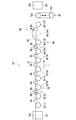
- the second capstans 42 (9), 42 (10),..., 42 (13), 42 as shown in FIG. A part of (14) and 42 (15) and a part of the dice 60 are omitted. More specifically, the wire 10 is allowed to pass without being wound around the second capstan 42 (14). Further, the die 60 disposed between the second capstans 42 (14) and 42 (15) is removed, and the second capstan 42 (13) and 42 (14) are disposed at that position. A die 60 is attached.
- the second capstan 42 (14) in front of the second capstan 42 (15), not the second capstan 42 (15) at the most downstream side is omitted because the second capstan 42 (15) at the most downstream side is finished. This is because a motor having a relatively large torque has been selected as the capstan for use.
- the plurality of second capstans 42 (9), 42 (10),..., 42 (13), 42 (14), 42 are temporarily set according to the material, the target diameter, and the like of the wire 10. ) Is set, all or part of the plurality of second capstans 42 (9), 42 (10),..., 42 (13), 42 (14), 42 (15) Depending on whether or not is used, the strands 10b having a plurality of types of finished wire diameters can be easily manufactured.
- the rotational speed of the second capstan 42 (9), 42 (10), ..., 42 (13), 42 (14), 42 (15) is changed and adjusted, Also, the die 60 may be replaced.
- one first rotation drive source 34 is connected to the plurality of first capstans 32 via the first rotation transmission mechanism unit 36.
- (1), 32 (2), ..., 32 (6), 32 (7), and 32 (8) are transmitted to each other, so that the maintenance work is easier than when the motors are individually driven. Can be achieved.
- the rotational speed of the several 2nd rotational drive source 44 is adjusted separately, and each 2nd capstan 42 (9), 42 (10), ..., 42 ( 13), 42 (14), 42 (15) by individually changing the rotational speed, the second capstans 42 (9), 42 (10), ..., 42 (13), 42 (14) , 42 (15) can be changed before and after the drawing speed ratio of the wire 10 can be changed.
- the finishing wire diameter used as the objective, etc. it can respond easily to the adjustment change of the diameter reduction deformation degree of the wire 10.
- the wire rod 10 can be efficiently drawn when the wire 10 has a relatively large diameter.
- the number of dies 60 can be reduced, which contributes to downsizing and cost reduction of the apparatus.
- the drawing speed ratio before and after the second capstans 42 (9), 42 (10),..., 42 (13), 42 (14), 42 (15) are involved is directed toward the downstream side. That is, it is set so that the smaller the wire 10 becomes, the smaller it becomes. In other words, the smaller the diameter of the wire 10 is, the smaller the degree of compression deformation by one die 60 is set. For this reason, the cutting
- FIG. 6 is a schematic plan view showing a wire drawing device 120 according to a modification. Note that the same components as those described in the above embodiment are denoted by the same reference numerals, description thereof will be omitted, and differences will be mainly described.
- the wire drawing device 120 includes a wire supply unit 22, a wire take-up unit 26, a first capstan mechanism unit 130, a second capstan mechanism unit 140, a finishing capstan mechanism unit 180, and a die 60. I have.
- the first capstan mechanism section 130 is provided between the wire rod supply section 22 and the wire rod take-up section 26 and on the wire rod supply section 22 side.
- a plurality (three in this case) of first capstans 132 (1) corresponding to the capstans 32 (1), 32 (2), ..., 32 (6), 32 (7), 32 (8), 132 (2), 132 (3), one first rotational drive source 134 corresponding to the first rotational drive source 34, and a first rotational transmission mechanism 136 corresponding to the first rotational transmission mechanism 36. have. That is, the first capstan mechanism 130 has the number of first capstans 132 (1), 132 (2), 132 (3) and the number of rotation driving force transmission targets of the first rotation transmission mechanism 136. Except for the differences, the configuration is the same as that of the first capstan mechanism 30.
- the second capstan mechanism 140 is between the wire supply unit 22 and the wire take-up part 26 and is closer to the wire take-up part 26 than the first capstan mechanism 130.
- Second capstans 142 (4), 142 (5), 142 (6), and a plurality (four in this case) of second rotation drive sources 144 corresponding to the respective second rotation drive sources 44 are provided. Yes.
- the second capstan mechanism part 140 is different from the second capstan 142 (4), 142 (5), 142 (6) in number, and the number of second rotational drive sources 144 in that the number of second capstans 142 (4), 142 (5), 142 (6) is different.
- the configuration is the same as that of the second capstan mechanism 40.
- the finishing capstan mechanism 180 pulls the wire 10 at a constant drawing speed.
- the finishing capstan mechanism 180 is between the wire supply unit 22 and the wire take-up unit 26 and takes up the wire more than the second capstan mechanism 140.
- a finishing transmission mechanism 184 that transmits the rotational driving force of the driving source 182 to a plurality of finishing capstans 182 (7), 182 (8), and 182 (9).
- the plurality of (here, three) finishing capstans 182 (7), 182 (8), 182 (9) are the first capstans 132 (1), 132 (2), 132 (3).
- the finishing rotation drive source 182 has the same configuration as the first rotation drive source 134, and the finishing transmission mechanism 184 has the same configuration as the first rotation transmission mechanism 136. Accordingly, the drawing speed ratio between the finishing capstans 182 (7), 182 (8) and 182 (9) in the finishing capstan mechanism 180 is a fixed constant value. However, the number of finishing capstans 182 (7), 182 (8), 182 (9) needs to be the same as the number of first capstans 132 (1), 132 (2), 132 (3). Absent. Further, there may be one pulling capstan.
- the die 60 includes a plurality of first capstans 132 (1), 132 (2), 132 (3), a plurality of second capstans 142 (4), 142 (5), 142 (6), A plurality of finishing capstans 182 (7), 182 (8), and 182 (9) are disposed between the respective capstans.
- the first capstan mechanism portion 130 performs wire drawing with a relatively large constant diameter reduction degree, and the second capstan mechanism portion 140 is adjusted according to the material of the wire 10.
- the drawing process can be performed with a reduced diameter deformation degree, and the finishing capstan mechanism 180 can perform the drawing process with a reduced diameter closed longitude suitable for finishing.
- finishing can be performed under certain conditions, there is an advantage that finishing quality is further stabilized.
- the drawing speed ratio in the second capstan mechanism portions 40 and 140 may be experimentally set and adjusted according to the material of the wire 10, the processing diameter, and the like.
- each diameter may be different.
- the drawing speed may be considered as a value obtained by adding the diameter to the rotation speed.
- the wire drawing line L is a straight line.
- the line is not necessarily required, and may be a line bent at each capstan portion or other guide roller portion.
Landscapes
- Engineering & Computer Science (AREA)
- Mechanical Engineering (AREA)
- Metal Extraction Processes (AREA)
Abstract
Description
Claims (6)
- 線材を伸線する伸線装置であって、
線材を供給する線材供給部と、
線材を引取る線材引取部と、
複数の第1キャプスタンと、1つの第1回転駆動源と、前記第1回転駆動源の回転駆動力を前記複数の第1キャプスタンに伝達する第1回転伝達機構部とを有し、前記線材供給部と前記線材引取部との間であって前記線材供給部側に設けられた第1キャプスタン機構部と、
複数の第2キャプスタンと、前記複数の第2キャプスタンをそれぞれ個別に回転駆動する複数の第2回転駆動源とを有し、前記線材供給部と前記線材引取部との間であって前記第1キャプスタン機構部よりも前記線材引取部側に設けられた第2キャプスタン機構部と、
前記複数の第1キャプスタン及び前記複数の第2キャプスタンの各間に配設されたダイス複数と、
を備える伸線装置。 - 請求項1記載の伸線装置であって、
前記複数の第2キャプスタン全てを経由した場合の線材の直径が、製造対象となる複数種の仕上り線径のうちの最も細径な仕上り線径となり、前記複数の第2キャプスタンのうちの一部を経由した場合の線材の直径が、製造対象となる複数種の仕上り線径のうちの1つの仕上り線径となるように、前記複数の第2キャプスタンの前後の引抜き速度比が設定されている、伸線装置。 - 請求項1記載の伸線装置であって、
前記複数の第2キャプスタンそれぞれに対する前後間の引抜き速度比が、前記線材引取部側に向けて徐々に小さくなるように設定されている、伸線装置。 - 請求項1記載の伸線装置であって、
伸線加工対象となる線材がアルミ線又はアルミ合金線であり、
直径0.5mm以下となった線材の伸線加工を、前記第2キャプスタンにより線材を引抜きつつ行うように、前記複数の第1キャプスタン間の引抜き速度比が設定されている、伸線装置。 - 請求項1記載の伸線装置であって、
少なくとも1つの仕上げ用キャプスタンと、1つの仕上げ用回転駆動源と、前記仕上げ用回転駆動源の回転駆動力を前記仕上げ用キャプスタンに伝達する仕上げ用伝達機構部とを有し、前記線材供給部と前記線材引取部との間であって前記第2キャプスタン機構部よりも前記線材引取部側に設けられた仕上げ用キャプスタン機構部をさらに備える伸線装置。 - 線材を伸線することによって素線を製造する素線の製造方法であって、
線材を供給する線材供給部と、
線材を引取る線材引取部と、
複数の第1キャプスタンと、1つの第1回転駆動源と、前記第1回転駆動源の回転駆動力を前記複数の第1キャプスタンに伝達する第1回転伝達機構部とを有し、前記線材供給部と前記線材引取部との間であって前記線材供給部側に設けられた第1キャプスタン機構部と、
複数の第2キャプスタンと、前記複数の第2キャプスタンをそれぞれ個別に回転駆動する複数の第2回転駆動源とを有し、前記線材供給部と前記線材引取部との間であって前記線材引取部側に設けられた第2キャプスタン機構部と、
前記複数の第1キャプスタン及び前記複数の第2キャプスタンの各間に配設されたダイス複数と、を備える伸線装置を用い、
前記複数の第2キャプスタン全てを経由した場合の線材の直径が、製造対象となる複数種の仕上り線径のうちの最も細径な仕上り線径となり、前記複数の第2キャプスタンのうちの一部を経由した場合の線材の直径が、製造対象となる複数種の仕上り線径のうちの1つの仕上り線径となるように、前記複数の第2キャプスタンの回転速度を設定し、
前記線材が経由する前記複数の第2キャプスタンの対象を全て又は一部に変更することで、複数種の仕上り線径の素線を製造する素線の製造方法。
Priority Applications (3)
| Application Number | Priority Date | Filing Date | Title |
|---|---|---|---|
| US13/266,616 US20120042707A1 (en) | 2009-07-02 | 2010-02-16 | Wire drawing device and method for manufacturing wire |
| CN201080029266.9A CN102470414B (zh) | 2009-07-02 | 2010-02-16 | 线材拉拔设备和用于制造线材的方法 |
| DE112010002786.2T DE112010002786B4 (de) | 2009-07-02 | 2010-02-16 | Drahtziehvorrichtung und Verfahren zum Herstellen eines Drahts |
Applications Claiming Priority (2)
| Application Number | Priority Date | Filing Date | Title |
|---|---|---|---|
| JP2009-158034 | 2009-07-02 | ||
| JP2009158034A JP5282683B2 (ja) | 2009-07-02 | 2009-07-02 | 伸線装置及び素線の製造方法 |
Publications (1)
| Publication Number | Publication Date |
|---|---|
| WO2011001703A1 true WO2011001703A1 (ja) | 2011-01-06 |
Family
ID=43410788
Family Applications (1)
| Application Number | Title | Priority Date | Filing Date |
|---|---|---|---|
| PCT/JP2010/052240 Ceased WO2011001703A1 (ja) | 2009-07-02 | 2010-02-16 | 伸線装置及び素線の製造方法 |
Country Status (5)
| Country | Link |
|---|---|
| US (1) | US20120042707A1 (ja) |
| JP (1) | JP5282683B2 (ja) |
| CN (1) | CN102470414B (ja) |
| DE (1) | DE112010002786B4 (ja) |
| WO (1) | WO2011001703A1 (ja) |
Families Citing this family (1)
| Publication number | Priority date | Publication date | Assignee | Title |
|---|---|---|---|---|
| CN110484787B (zh) * | 2019-08-20 | 2020-07-24 | 北京有色金属与稀土应用研究所 | 一种高纯铝镁合金微细丝及其制备方法和应用 |
Citations (3)
| Publication number | Priority date | Publication date | Assignee | Title |
|---|---|---|---|---|
| EP0346534A2 (en) * | 1988-06-13 | 1989-12-20 | Ceeco Machinery Manufacturing Ltd. | Wire drawing apparatus and method |
| JPH0471715A (ja) * | 1990-07-09 | 1992-03-06 | Hitachi Cable Ltd | 線材連続マルチ伸線機 |
| JPH07155826A (ja) * | 1993-12-06 | 1995-06-20 | Hitachi Cable Ltd | 伸線ラインの速度制御方法 |
Family Cites Families (10)
| Publication number | Priority date | Publication date | Assignee | Title |
|---|---|---|---|---|
| US2220048A (en) * | 1932-03-02 | 1940-10-29 | Gen Cable Corp | Apparatus for drawing wire |
| GB1126671A (en) * | 1964-12-22 | 1968-09-11 | British Ropes Ltd | Manufacture of wire strands |
| US3686908A (en) * | 1971-02-01 | 1972-08-29 | Wire Technology And Machinery | Wire drawing apparatus and method |
| US3979940A (en) * | 1972-10-19 | 1976-09-14 | British Insulated Callender's Cables Limited | Wire drawing machinery |
| DE3314747A1 (de) * | 1983-04-23 | 1984-10-31 | Maschinenfabrik Niehoff Kg, 8540 Schwabach | Verfahren und vorrichtung zum herstellen von stahlcords, insbesondere fuer kraftfahrzeugreifen |
| US4750344A (en) * | 1985-11-01 | 1988-06-14 | Ceeco Machinery Manufacturing Limited | Wire drawing apparatus and method |
| JPH1147821A (ja) | 1997-08-06 | 1999-02-23 | Furukawa Electric Co Ltd:The | スリップ式連続伸線機 |
| CN1185057C (zh) * | 2000-09-26 | 2005-01-19 | 江苏兴达钢帘线股份有限公司 | 一种金属线材加工方法及拉丝机 |
| JP3771918B2 (ja) | 2003-10-01 | 2006-05-10 | 有限会社エフ・エー電子 | 伸線機 |
| CN201020480Y (zh) * | 2007-04-02 | 2008-02-13 | 郑波 | 拉丝机 |
-
2009
- 2009-07-02 JP JP2009158034A patent/JP5282683B2/ja not_active Expired - Fee Related
-
2010
- 2010-02-16 DE DE112010002786.2T patent/DE112010002786B4/de not_active Expired - Fee Related
- 2010-02-16 WO PCT/JP2010/052240 patent/WO2011001703A1/ja not_active Ceased
- 2010-02-16 CN CN201080029266.9A patent/CN102470414B/zh not_active Expired - Fee Related
- 2010-02-16 US US13/266,616 patent/US20120042707A1/en not_active Abandoned
Patent Citations (3)
| Publication number | Priority date | Publication date | Assignee | Title |
|---|---|---|---|---|
| EP0346534A2 (en) * | 1988-06-13 | 1989-12-20 | Ceeco Machinery Manufacturing Ltd. | Wire drawing apparatus and method |
| JPH0471715A (ja) * | 1990-07-09 | 1992-03-06 | Hitachi Cable Ltd | 線材連続マルチ伸線機 |
| JPH07155826A (ja) * | 1993-12-06 | 1995-06-20 | Hitachi Cable Ltd | 伸線ラインの速度制御方法 |
Also Published As
| Publication number | Publication date |
|---|---|
| JP5282683B2 (ja) | 2013-09-04 |
| JP2011011236A (ja) | 2011-01-20 |
| DE112010002786B4 (de) | 2015-06-03 |
| CN102470414A (zh) | 2012-05-23 |
| US20120042707A1 (en) | 2012-02-23 |
| DE112010002786T5 (de) | 2012-11-08 |
| CN102470414B (zh) | 2014-11-05 |
Similar Documents
| Publication | Publication Date | Title |
|---|---|---|
| JP3918132B1 (ja) | 伸線機と伸線方法 | |
| CN201773646U (zh) | 一种钢铝包钢绞线电缆成形机 | |
| US20090241314A1 (en) | Twisted wire and method of producing twisted wire | |
| JP2015514013A (ja) | 伸線装置 | |
| JP5181895B2 (ja) | 撚り合せ電線の製造装置、撚り合せ電線の製造方法及び撚り合せ電線 | |
| JP5282683B2 (ja) | 伸線装置及び素線の製造方法 | |
| JP5105963B2 (ja) | 湿式伸線機 | |
| JPH10244339A (ja) | 撚線製造装置 | |
| CN107633923B (zh) | 一种金属丝集合机 | |
| JP2015036149A (ja) | 伸線装置及び素線の製造方法 | |
| CN211237825U (zh) | 一种高速绞线机 | |
| JP2003249133A (ja) | 線材繰出装置 | |
| JP2016015239A (ja) | ケーブル、撚線の製造方法、及び、撚線製造装置 | |
| CN103046411A (zh) | 丝绳绕制机自动收线排线机构 | |
| JP5195633B2 (ja) | 銅線の製造方法および銅線 | |
| JP5004287B2 (ja) | 撚線機およびそれを用いた撚線の製造方法 | |
| JP6259519B2 (ja) | ツイスト線製造装置、及び、ツイスト線製造方法 | |
| JP2006328603A (ja) | 極細撚線の製造方法及び製造装置 | |
| JP5814390B2 (ja) | 伸線機 | |
| JP2559467B2 (ja) | 撚線装置 | |
| JP2003053418A (ja) | 金極細ワイヤの伸線方法及び伸線装置 | |
| JP2003025011A (ja) | 湿式伸線機 | |
| JP2013146738A (ja) | 金属細線の伸線方法及びこれを用いたボンディングワイヤの製造方法 | |
| CN207068555U (zh) | 一种新型金属丝集合机 | |
| JPH1094802A (ja) | 細径線材の製造装置および製造方法 |
Legal Events
| Date | Code | Title | Description |
|---|---|---|---|
| WWE | Wipo information: entry into national phase |
Ref document number: 201080029266.9 Country of ref document: CN |
|
| 121 | Ep: the epo has been informed by wipo that ep was designated in this application |
Ref document number: 10793874 Country of ref document: EP Kind code of ref document: A1 |
|
| WWE | Wipo information: entry into national phase |
Ref document number: 13266616 Country of ref document: US |
|
| WWE | Wipo information: entry into national phase |
Ref document number: 112010002786 Country of ref document: DE Ref document number: 1120100027862 Country of ref document: DE |
|
| 122 | Ep: pct application non-entry in european phase |
Ref document number: 10793874 Country of ref document: EP Kind code of ref document: A1 |