WO2010146683A1 - 光学ユニットおよび投写型表示装置 - Google Patents
光学ユニットおよび投写型表示装置 Download PDFInfo
- Publication number
- WO2010146683A1 WO2010146683A1 PCT/JP2009/061089 JP2009061089W WO2010146683A1 WO 2010146683 A1 WO2010146683 A1 WO 2010146683A1 JP 2009061089 W JP2009061089 W JP 2009061089W WO 2010146683 A1 WO2010146683 A1 WO 2010146683A1
- Authority
- WO
- WIPO (PCT)
- Prior art keywords
- light
- light source
- optical
- projection display
- color wheel
- Prior art date
Links
- 230000003287 optical effect Effects 0.000 title claims abstract description 46
- 238000006243 chemical reaction Methods 0.000 claims description 11
- 238000000926 separation method Methods 0.000 description 15
- 238000010586 diagram Methods 0.000 description 13
- 239000003086 colorant Substances 0.000 description 4
- 239000011521 glass Substances 0.000 description 4
- 238000013459 approach Methods 0.000 description 2
- 230000004907 flux Effects 0.000 description 2
- 238000002834 transmittance Methods 0.000 description 2
- 239000011248 coating agent Substances 0.000 description 1
- 238000000576 coating method Methods 0.000 description 1
- 229910052736 halogen Inorganic materials 0.000 description 1
- 150000002367 halogens Chemical class 0.000 description 1
- 238000004519 manufacturing process Methods 0.000 description 1
- 239000011159 matrix material Substances 0.000 description 1
- QSHDDOUJBYECFT-UHFFFAOYSA-N mercury Chemical compound [Hg] QSHDDOUJBYECFT-UHFFFAOYSA-N 0.000 description 1
- 229910052753 mercury Inorganic materials 0.000 description 1
- 229910001507 metal halide Inorganic materials 0.000 description 1
- 150000005309 metal halides Chemical class 0.000 description 1
- 230000004048 modification Effects 0.000 description 1
- 238000012986 modification Methods 0.000 description 1
- 239000004065 semiconductor Substances 0.000 description 1
- 230000002194 synthesizing effect Effects 0.000 description 1
- 229910052724 xenon Inorganic materials 0.000 description 1
- FHNFHKCVQCLJFQ-UHFFFAOYSA-N xenon atom Chemical compound [Xe] FHNFHKCVQCLJFQ-UHFFFAOYSA-N 0.000 description 1
Images


Classifications
-
- G—PHYSICS
- G03—PHOTOGRAPHY; CINEMATOGRAPHY; ANALOGOUS TECHNIQUES USING WAVES OTHER THAN OPTICAL WAVES; ELECTROGRAPHY; HOLOGRAPHY
- G03B—APPARATUS OR ARRANGEMENTS FOR TAKING PHOTOGRAPHS OR FOR PROJECTING OR VIEWING THEM; APPARATUS OR ARRANGEMENTS EMPLOYING ANALOGOUS TECHNIQUES USING WAVES OTHER THAN OPTICAL WAVES; ACCESSORIES THEREFOR
- G03B21/00—Projectors or projection-type viewers; Accessories therefor
- G03B21/14—Details
- G03B21/20—Lamp housings
- G03B21/2006—Lamp housings characterised by the light source
- G03B21/2013—Plural light sources
-
- G—PHYSICS
- G03—PHOTOGRAPHY; CINEMATOGRAPHY; ANALOGOUS TECHNIQUES USING WAVES OTHER THAN OPTICAL WAVES; ELECTROGRAPHY; HOLOGRAPHY
- G03B—APPARATUS OR ARRANGEMENTS FOR TAKING PHOTOGRAPHS OR FOR PROJECTING OR VIEWING THEM; APPARATUS OR ARRANGEMENTS EMPLOYING ANALOGOUS TECHNIQUES USING WAVES OTHER THAN OPTICAL WAVES; ACCESSORIES THEREFOR
- G03B21/00—Projectors or projection-type viewers; Accessories therefor
- G03B21/14—Details
- G03B21/20—Lamp housings
- G03B21/2006—Lamp housings characterised by the light source
- G03B21/202—Incandescent light sources
-
- G—PHYSICS
- G03—PHOTOGRAPHY; CINEMATOGRAPHY; ANALOGOUS TECHNIQUES USING WAVES OTHER THAN OPTICAL WAVES; ELECTROGRAPHY; HOLOGRAPHY
- G03B—APPARATUS OR ARRANGEMENTS FOR TAKING PHOTOGRAPHS OR FOR PROJECTING OR VIEWING THEM; APPARATUS OR ARRANGEMENTS EMPLOYING ANALOGOUS TECHNIQUES USING WAVES OTHER THAN OPTICAL WAVES; ACCESSORIES THEREFOR
- G03B21/00—Projectors or projection-type viewers; Accessories therefor
- G03B21/14—Details
- G03B21/20—Lamp housings
- G03B21/2006—Lamp housings characterised by the light source
- G03B21/2026—Gas discharge type light sources, e.g. arcs
-
- G—PHYSICS
- G03—PHOTOGRAPHY; CINEMATOGRAPHY; ANALOGOUS TECHNIQUES USING WAVES OTHER THAN OPTICAL WAVES; ELECTROGRAPHY; HOLOGRAPHY
- G03B—APPARATUS OR ARRANGEMENTS FOR TAKING PHOTOGRAPHS OR FOR PROJECTING OR VIEWING THEM; APPARATUS OR ARRANGEMENTS EMPLOYING ANALOGOUS TECHNIQUES USING WAVES OTHER THAN OPTICAL WAVES; ACCESSORIES THEREFOR
- G03B21/00—Projectors or projection-type viewers; Accessories therefor
- G03B21/14—Details
- G03B21/20—Lamp housings
- G03B21/2066—Reflectors in illumination beam
-
- G—PHYSICS
- G03—PHOTOGRAPHY; CINEMATOGRAPHY; ANALOGOUS TECHNIQUES USING WAVES OTHER THAN OPTICAL WAVES; ELECTROGRAPHY; HOLOGRAPHY
- G03B—APPARATUS OR ARRANGEMENTS FOR TAKING PHOTOGRAPHS OR FOR PROJECTING OR VIEWING THEM; APPARATUS OR ARRANGEMENTS EMPLOYING ANALOGOUS TECHNIQUES USING WAVES OTHER THAN OPTICAL WAVES; ACCESSORIES THEREFOR
- G03B21/00—Projectors or projection-type viewers; Accessories therefor
- G03B21/14—Details
- G03B21/20—Lamp housings
- G03B21/208—Homogenising, shaping of the illumination light
-
- G—PHYSICS
- G03—PHOTOGRAPHY; CINEMATOGRAPHY; ANALOGOUS TECHNIQUES USING WAVES OTHER THAN OPTICAL WAVES; ELECTROGRAPHY; HOLOGRAPHY
- G03B—APPARATUS OR ARRANGEMENTS FOR TAKING PHOTOGRAPHS OR FOR PROJECTING OR VIEWING THEM; APPARATUS OR ARRANGEMENTS EMPLOYING ANALOGOUS TECHNIQUES USING WAVES OTHER THAN OPTICAL WAVES; ACCESSORIES THEREFOR
- G03B33/00—Colour photography, other than mere exposure or projection of a colour film
- G03B33/08—Sequential recording or projection
-
- H—ELECTRICITY
- H04—ELECTRIC COMMUNICATION TECHNIQUE
- H04N—PICTORIAL COMMUNICATION, e.g. TELEVISION
- H04N9/00—Details of colour television systems
- H04N9/12—Picture reproducers
- H04N9/31—Projection devices for colour picture display, e.g. using electronic spatial light modulators [ESLM]
- H04N9/3102—Projection devices for colour picture display, e.g. using electronic spatial light modulators [ESLM] using two-dimensional electronic spatial light modulators
- H04N9/3111—Projection devices for colour picture display, e.g. using electronic spatial light modulators [ESLM] using two-dimensional electronic spatial light modulators for displaying the colours sequentially, e.g. by using sequentially activated light sources
- H04N9/3114—Projection devices for colour picture display, e.g. using electronic spatial light modulators [ESLM] using two-dimensional electronic spatial light modulators for displaying the colours sequentially, e.g. by using sequentially activated light sources by using a sequential colour filter producing one colour at a time
-
- H—ELECTRICITY
- H04—ELECTRIC COMMUNICATION TECHNIQUE
- H04N—PICTORIAL COMMUNICATION, e.g. TELEVISION
- H04N9/00—Details of colour television systems
- H04N9/12—Picture reproducers
- H04N9/31—Projection devices for colour picture display, e.g. using electronic spatial light modulators [ESLM]
- H04N9/3141—Constructional details thereof
- H04N9/315—Modulator illumination systems
- H04N9/3164—Modulator illumination systems using multiple light sources
Definitions
- the present invention relates to an optical unit including two light sources and a projection display device.
- Some projection display devices include two light sources in order to obtain high-luminance light.
- high-intensity light can be obtained by combining the light emitted from each light source.
- FIG. 1 is a schematic configuration diagram showing an internal mechanism of a projection display device having two light sources.
- This projection display apparatus has two light sources 401a and 401b arranged side by side. The two light sources 401a and 401b are directed in the same direction.
- the color wheel 402 is a disk-shaped member provided with a color filter having translucency.
- the color filter is divided into a plurality of color separation regions in the circumferential direction. Each color separation region selectively transmits only light having a wavelength of any one of red, green, and blue.
- the color wheel 402 can rotate around the central axis. By rotating the color wheel 402, the color separation region that transmits the light emitted from the light sources 401a and 401b is continuously changed.
- the rod lenses 404a and 404b are rod-shaped glass members having a rectangular cross section.
- the light incident on one end of the rod lenses 404a and 404b passes through the rod lenses 404a and 404b and is emitted from the other end.
- this light is transmitted from one end of the rod lenses 404a and 404b to the other end, it is repeatedly totally reflected by the side surfaces of the rod lenses 404a and 404b, so that the luminance distribution is made uniform.
- Each light emitted from the rod lenses 404a and 404b passes through the condenser lenses 405a and 405b and then enters the condenser lens 406.
- the light transmitted through the condenser lens 406 is reflected by the flat mirror 407 and then enters the condenser lens 408.
- DMD Digital Micromirror Device
- the DMD 409 is an image forming element in which a number of mirror elements that can be individually switched on and off based on an image signal are attached on a semiconductor memory cell. Light that is incident on the DMD 409 and modulated by being reflected by each mirror element of the DMD 409 is enlarged and projected from the projection lens 411 onto a screen (not shown).
- each light emitted from the rod lenses 404a and 404b gradually approaches each other when passing through the condenser lenses 406 and 408 sequentially. Then, each light overlaps each other and becomes one light beam and enters the DMD 409. In this way, in this projection display device, the light emitted from the two light sources 401a and 401b is synthesized by the condenser lenses 406 and 408, so that one image can be displayed on the screen.
- each light emitted from the light sources 401a and 401b is incident on the color filter of the color wheel 402 at positions facing each other across the central axis.
- the color wheel 402 must always have the same color for the light emitted from the light source 401a and the light emitted from the light source 401b.
- the color filter of the color wheel 402 needs to have a pair of color separation regions facing each other across the central axis for each color. That is, the color filter of the color wheel 402 needs to be divided into six color separation regions in the circumferential direction.
- this projection display device when the light emitted from the light sources 401a and 401b passes through the color separation region of the same color, light of any one color of red, green, and blue can be obtained. However, when the light emitted from the light sources 401a and 401b is transmitted across the boundary between the two color separation regions, the two colors are mixed. Light of a color in which these two colors are mixed is not used for displaying an image. Therefore, all the mirror elements of the DMD 409 are turned off while the light emitted from the light sources 401a and 401b is incident on the two color separation regions.
- the number of colors of light required for displaying an image is three, that is, red, green, and blue, whereas the number of color filters is twice that number. It must be divided into two color separation areas. Therefore, the number of times that the mirror elements of the DMD 409 are all turned off during one rotation of the color wheel 402 is three times in the case of three color separation regions, but six times in this projection display device. For this reason, in the projection display device, the light emitted from the light sources 401a and 401b cannot be efficiently used for displaying an image.
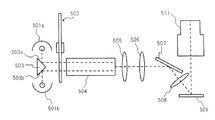
- FIG. 2A is a schematic configuration diagram showing an internal mechanism of a projection display device that includes two light sources and is configured such that light emitted from each light source passes through the same color separation region of the color filter.
- the projection display apparatus shown in FIG. 2A has the same configuration as that of the projection display apparatus shown in FIG. 1 except for the configuration shown below.
- the projection display device has a triangular prism 503 having surfaces 503a and 503b on which mirror coating is applied.
- each light emitted from the light sources 501 a and 501 b is reflected by the surfaces 503 a and 503 b of the triangular prism 503, and after passing through positions close to each other of the color filters of the color wheel 502, Incident on one end. Therefore, in this projection display device, each light emitted from the light sources 501a and 501b can be transmitted through the same color separation region of the color filter. Therefore, it is sufficient that the color filter is divided into three color separation regions, which is the same number as the number of light colors required for displaying an image.
- each color separation region of the color filter needs to have a size that can transmit both the light emitted from the light sources 501a and 501b. Therefore, in this projection display device, it is necessary to form a color filter larger than in the case where there is one light source.
- the relative positions of the light sources 501a and 501b and the triangular prism 503 are changed so that the light beams 512a and 512b from the light sources 501a and 501b enter the color wheel 502 as one light beam. It is possible. This eliminates the need to form a large color filter.
- the shape of the prism can be changed so that the two light beams 513a and 513b from the light sources 501a and 501b intersect at the color wheel 502.
- light emitted from the light sources 501a and 501b passes through the same position of the color filter of the color wheel 502. Therefore, it is not necessary to increase the size of the color filter.
- an object of the present invention is to provide a compact optical unit and a projection display device provided with two light sources.
- an optical unit includes a first light source, a second light source disposed to face the first light source, the first light source, and the second light source.
- a color wheel disposed between the light source and the color wheel that totally reflects light emitted from the first light source and transmitted through the color wheel and transmits light emitted from the second light source.
- a first optical path changing unit that is incident on the light source, and a total reflection of the light emitted from the second light source and transmitted through the color wheel, and the light emitted from the first light source is transmitted to the color.
- a second optical path conversion unit that is incident on the wheel.
- a compact optical unit including two light sources and a projection display device.
- FIG. 1 is a schematic configuration diagram showing an internal mechanism of a projection display device according to a first embodiment of the present invention. It is the elements on larger scale which showed the internal mechanism of the projection type display apparatus shown to FIG. 3A.
- FIG. 1 is a schematic configuration diagram showing an internal mechanism of a projection display device according to a first embodiment of the present invention. It is the elements on larger scale which showed the internal mechanism of the projection type display apparatus shown to FIG. 3A.
- FIG. 3B is a perspective view of a projection display device including the internal mechanism illustrated in FIG. 3A. It is the schematic block diagram which showed the internal mechanism of the projection type display apparatus which concerns on the 2nd Embodiment of this invention. It is the schematic block diagram which showed the internal mechanism of the projection type display apparatus which concerns on the 3rd Embodiment of this invention. It is the schematic block diagram which showed the internal mechanism of the projection type display apparatus which concerns on the 4th Embodiment of this invention. It is a schematic block diagram which showed the modification of the internal mechanism of the projection type display apparatus shown to FIG. 7A.
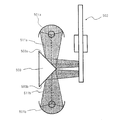
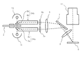
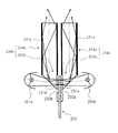
- FIG. 3A is a schematic configuration diagram showing an internal mechanism of the projection display apparatus according to the first embodiment of the present invention.
- FIG. 3B is an enlarged view of the light source, color wheel, and light guide rod shown in FIG. 3A.
- the projection display device has two light sources 1a and 1b arranged to face each other.
- Ultra high pressure mercury lamps are used as the light sources 1a and 1b.
- a metal halide lamp, a halogen lamp, a xenon lamp, or the like can be used as the light source.
- a color wheel 2 is provided between the light sources 1a and 1b.
- the color wheel 2 includes a color filter 22 having translucency and a motor 21 for rotating the color wheel 2 around the central axis.
- the projection display device also has two light guide rods 34a and 34b formed in a rod shape.
- the light guide rods 34a and 34b are made of, for example, glass such as BK7 having a transmittance of light in the visible region (wavelength 400 nm to 700 nm) of 99.4% or more.
- the light guide rods 34a and 34b are arranged in parallel.
- the light guide rod 34a is provided with a prism portion 3a at one end.
- the prism portion 3 a is disposed between the light source 1 b and the color wheel 2.
- the surface on the light source 1b side of the prism portion 3a is an inclined surface 31a inclined obliquely with respect to the longitudinal direction of the light guide rod 34a.
- the light guide rod 34a is provided with a rod lens portion 4a extending from the prism portion 3a to the other end of the light guide rod 34a.
- the rod lens portion 4a has a rectangular cross section.
- the light guide rod 34b is provided with a prism portion 3b at one end.
- the prism portion 3 b is disposed between the light source 1 a and the color wheel 2.
- the surface on the light source 1a side of the prism portion 3b is an inclined surface 31b inclined obliquely with respect to the longitudinal direction of the light guide rod 34b.
- the light guide rod 34b is provided with a rod lens portion 4b extending from the prism portion 3b to the other end of the light guide rod 34b.
- the rod lens portion 4b has a rectangular cross section.
- the light emitted from the light source 1a first enters the inclined surface 31b of the prism portion 3b, passes through the prism portion 3b, and is emitted from the surface 32b.
- the light emitted from the surface 32 b of the prism portion 3 b enters the color filter 22 of the color wheel 2.
- the light emitted from the light source 1a and transmitted through the color filter 22 enters the surface 32a of the prism portion 3a, passes through the prism portion 3a, and enters the inclined surface 31a from the inside of the prism portion 3a.
- the prism part 3a is formed so that the incident angle of the light emitted from the light source 1a when entering the inclined surface 31a is larger than the critical angle.
- the prism unit 3a functions as a first optical path conversion unit that changes the traveling direction of the light emitted from the light source 1a and guides the light emitted from the light source 1a to one end of the rod lens 4a. To do.
- the light incident on the rod lens portion 4a is transmitted through the rod lens portion 4a and emitted from the other end portion.
- this light is transmitted from one end of the rod lens 4a to the other end, it is repeatedly totally reflected by the side surface of the rod lens 4a, so that the luminance distribution is made uniform.
- the light emitted from the light source 1b first enters the inclined surface 31a of the prism portion 3a, passes through the prism portion 3a, and is emitted from the surface 32a.
- the light emitted from the surface 32a of the prism portion 3a is located at the same position as the position where the light emitted from the light source 1a of the color filter 22 of the color wheel 2 is transmitted from the side opposite to the light emitted from the light source 1a.
- each light emitted from the light sources 1a and 1b passes through the same position from both sides of the color filter 22, so that the color separation region of the color filter 22 needs to be increased. There is no. Therefore, although the projection display apparatus includes two light sources, the size of the color filter 22 may be the same as that of a single light source.
- the light emitted from the light source 1b and transmitted through the color filter 22 enters the surface 32b of the prism portion 3b, passes through the prism portion 3b, and enters the inclined surface 31b from the inside of the prism portion 3b.
- the prism portion 3b is formed so that the incident angle of the light emitted from the light source 1b when entering the inclined surface 31b is larger than the critical angle.
- the prism unit 3b functions as a second optical path conversion unit that changes the traveling direction of the light emitted from the light source 1b and guides the light emitted from the light source 1b to one end of the rod lens 4b. To do.
- the light incident on the rod lens portion 4b is transmitted through the rod lens portion 4b and emitted from the other end.
- this light is transmitted from one end of the rod lens 4b to the other end, it is repeatedly totally reflected by the side surface of the rod lens 4b, so that the luminance distribution is made uniform.
- the prism portions 3a and 3b and the rod lens portions 4a and 4b are integrally formed, so that the number of parts is reduced as compared with the case where they are provided as separate members. Thereby, the manufacturing cost is reduced.
- each light emitted from the rod lens portions 4a and 4b passes through the condenser lenses 5a and 5b, and then enters the condenser lens 6.
- the light that has passed through the condenser lens 6 is reflected by the plane mirror 7, passes through the condenser lens 8, and then enters the DMD 9.
- the condenser lenses 5a, 5b, 6, 8 and the plane mirror 7 constitute a relay optical system for guiding light to the DMD 9.
- the light transmitted through the condenser lenses 5a and 5b gradually approach each other as it sequentially passes through the condenser lenses 6 and 8. Then, each light overlaps each other and becomes almost one light beam and enters the DMD 9. That is, the condenser lenses 6 and 8 function as a relay optical system and function as a combining mechanism that combines the light emitted from the light sources 1a and 1b. As a result, the light incident on the DMD 9 is twice as bright as the light when there is one light source.
- the configuration described above is an optical unit for color-separating, uniformizing, and synthesizing each light emitted from the two light sources 1a and 1b in the projection display device according to the present embodiment. Therefore, the projection display apparatus includes the optical unit, so that the color-separated uniform and bright light can be incident on the DMD 9 as the irradiation object.
- the light emitted from the optical unit and incident on the DMD 9 is modulated by being reflected by each mirror element provided in the DMD 9.
- the light modulated by the DMD 9 is enlarged and projected from the projection lens 11 onto a screen (not shown).
- the DMD 9 can be changed to another image forming element, and the projection lens 11 can be changed to another projection optical system.
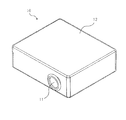
- FIG. 4 is a perspective view of a projection display device including the internal mechanism shown in FIG. 3A.
- the internal mechanism shown in FIG. 3A is covered by the housing 12, and the projection lens 11 is exposed on the side surface of the housing 12.
- an image is displayed on the screen by operating the internal mechanism and projecting light from the projection lens 11 as described above.
- bright light can be incident on the DMD 9 by the optical unit described above, so that a bright and clear image can be displayed on the screen.
- FIG. 5 is a schematic configuration diagram showing the internal mechanism of the projection display apparatus according to the second embodiment of the present invention.
- the projection display apparatus according to this embodiment has the same configuration as that of the projection display apparatus according to the first embodiment, except for the configuration described below.
- the projection display device includes collimator lenses 151a and 151b, a first fly-eye lens 152, and a second fly-eye lens 153.
- the collimating lenses 151a and 151b are lenses that convert diffused light into parallel light.
- the fly-eye lenses 152 and 153 are lenses in which a plurality of single lenses each having a convex surface and a flat surface are arranged in a matrix.
- the fly-eye lenses 152 and 153 face each other on the plane side.
- the light emitted from the light sources 101a and 101b passes through the color wheel 102, is totally reflected by the prism portions 103a and 103b, and then enters the rod lens portions 104a and 104b.
- the light transmitted through the rod lens portions 104a and 104b is transmitted through the collimating lenses 151a and 151b and converted from diffused light to parallel light.
- the parallel light transmitted through the collimating lenses 151a and 151b enters the first fly-eye lens 152 from the convex surface side. Further, the light transmitted through the first fly-eye lens 152 enters the second fly-eye lens 153 from the plane side. The light is superimposed when passing through the fly-eye lenses 152 and 153, and the luminance distribution becomes uniform.
- the light having a uniform luminance distribution transmitted through the fly-eye lenses 152 and 153 is transmitted through the field lens 106, reflected by the plane mirror 107, and further transmitted through the condenser lens 108.
- the light transmitted through the condenser lens 108 is modulated by the DMD 109 and then enlarged and projected from the projection lens 111 onto the screen.
- the collimating lenses 151a and 151b, the first fly-eye lens 152, and the second fly-eye lens 153 function as an integrator optical system that uniformizes the light luminance distribution. Therefore, the rod lens portions 104a and 104b do not have to have a function of uniforming the light luminance distribution. Therefore, in the present embodiment, the rod lens portions 104a and 104b of the light guide rods 134a and 134b can be formed short.
- FIG. 6 is a schematic configuration diagram showing an internal mechanism of a projection display device according to the third embodiment of the present invention.
- the projection display apparatus according to this embodiment has the same configuration as that of the projection display apparatus according to the first embodiment, except for the configuration described below.
- mirror coats 241a and 241b are applied to the side surfaces of the rod lens portions 204a and 204b of the light guide rods 234a and 234b.
- the side surface of the rod lens part is not mirror coated, if dirt adheres to the side surface of the rod lens part, the light transmitted through the rod lens part is not totally reflected by the side surface of the rod lens part, but the rod lens part Will be released out of the. Therefore, management for keeping the light guide rod in a state in which dirt is not attached is very important.
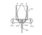
- FIG. 7A is a schematic configuration diagram showing an internal mechanism of a projection display apparatus according to the fourth embodiment of the present invention.
- the projection display apparatus according to this embodiment has the same configuration as that of the projection display apparatus according to the first embodiment, except for the configuration described below.
- the projection display device includes prisms 303a and 303b corresponding to the prism portions 3a and 3b, and a rod lens portion instead of the light guide rods 34a and 34b according to the first embodiment shown in FIG. 3B.
- Light tunnels 304a and 304b corresponding to 4a and 4b.
- the prisms 303a and 303b are glass members on which inclined surfaces 331a and 331b are formed.
- the light tunnels 304a and 304b are cylindrical members combined with the mirror surfaces of four rectangular flat mirrors facing inward.
- the light emitted from the light sources 301a and 301b is transmitted through the color wheel 302 and totally reflected by the inclined surfaces 331a and 331b of the prisms 303a and 303b, and then one end of the light tunnels 304a and 304b. Incident on the part.
- the light incident on the light tunnels 304a and 304b passes through the light tunnels 304a and 304b and is emitted from the other end.
- this light is transmitted from one end of the light tunnels 304a and 304b to the other end, it is repeatedly reflected by the mirror surfaces of the light tunnels 304a and 304b, so that the luminance distribution is made uniform.
- the light tunnels 304a and 304b which are hollow inside, can pass light more efficiently than a rod lens. Therefore, in the projection display apparatus according to the present embodiment, it is possible to reduce light loss when the light luminance distribution is made uniform. Therefore, this projection display device can display a bright image.
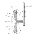
- the projection display device there are two light tunnels 304a and 304b that equalize the luminance distribution of each light totally reflected by the inclined surfaces 331a and 331b of the prisms 303a and 303b for each light. Is provided. However, there may be one light tunnel as shown in FIG. 7B.
- the light totally reflected by the inclined surfaces 331a and 331b of the prisms 303a and 303b is incident on one end of the light tunnel 304.
- Each light incident on one end of the light tunnel 304 has a uniform luminance distribution when passing through the light tunnel 304, and is emitted as one light flux from the other end.
- the light tunnel 304 has a function of uniforming the luminance distribution of light, and also has a function of combining the lights emitted from the light sources 301a and 301b.
Abstract
Description
(第1の実施形態)
図3Aは本発明の第1の実施形態に係る投写型表示装置の内部機構を示した概略構成図である。また、図3Bは図3Aに示した光源、カラーホイールおよび導光ロッドを拡大して示した図である。
(第2の実施形態)
図5は本発明の第2の実施形態に係る投写型表示装置の内部機構を示した概略構成図である。本実施形態に係る投写型表示装置は、以下に示す構成以外は第1の実施形態に係る投写型表示装置と同様の構成である。
(第3の実施形態)
図6は本発明の第3の実施形態に係る投写型表示装置の内部機構を示した概略構成図である。本実施形態に係る投写型表示装置は、以下に示す構成以外は第1の実施形態に係る投写型表示装置と同様の構成である。
(第4の実施形態)
図7Aは本発明の第4の実施形態に係る投写型表示装置の内部機構を示した概略構成図である。本実施形態に係る投写型表示装置は、以下に示す構成以外は第1の実施形態に係る投写型表示装置と同様の構成である。
2 カラーホイール
3a,3b プリズム部
4a,4b ロッドレンズ部
5a,5b,6,8 コンデンサレンズ
7 平面ミラー
9 DMD
10 投写型表示装置
11 投写レンズ
34a,34b 導光ロッド
Claims (10)
- 第1の光源と、
前記第1の光源に対向して配置された第2の光源と、
前記第1の光源と前記第2の光源との間に配置されたカラーホイールと、
前記第1の光源から発せられて前記カラーホイールを透過した光を全反射し、かつ、前記第2の光源から発せられた光を透過させて前記カラーホイールに入射させる第1の光路変換部と、
前記第2の光源から発せられて前記カラーホイールを透過した光を全反射し、かつ、前記第1の光源から発せられた光を透過させて前記カラーホイールに入射させる第2の光路変換部と、
を有する光学ユニット。 - 前記第1の光路変換部に全反射された光と前記第2の光路変換部に全反射された光との輝度分布を均一化するインテグレータ光学系を有する、請求項1に記載の光学ユニット。
- 前記第1の光路変換部に全反射された光が入射する第1のインテグレータ光学系と、前記第2の光路変換部に全反射された光が入射する第2のインテグレータ光学系と、を含んでいる、請求項2に記載の光学ユニット。
- 前記第1の光路変換部と前記第1のインテグレータ光学系とが一体に形成され、前記第2の光路変換部と前記第2のインテグレータ光学系とが一体に形成されている、請求項3に記載の光学ユニット。
- 前記インテグレータ光学系はロッドレンズを含んでいる、請求項2から4のいずれか1項に記載の光学ユニット。
- 前記ロッドレンズの側面にミラーコートが施されている、請求項5に記載の光学ユニット。
- 前記インテグレータ光学系は内側にミラー面が設けられた筒状部材を含んでいる、請求項2または3に記載の光学ユニット。
- 前記インテグレータ光学系はフライアイレンズを含んでいる、請求項2または3に記載の光学ユニット。
- 請求項1から8のいずれか1項に記載の光学ユニットと、該光学ユニットから照射された光を画像信号に基づいて変調する画像形成素子と、該画像形成素子に変調された光を投写する投写光学系と、を有する投写型表示装置。
- 前記画像形成素子はDMDである、請求項9に記載の投写型表示装置。
Priority Applications (3)
| Application Number | Priority Date | Filing Date | Title |
|---|---|---|---|
| JP2011519361A JP4953149B2 (ja) | 2009-06-18 | 2009-06-18 | 光学ユニットおよび投写型表示装置 |
| US13/375,762 US8851684B2 (en) | 2009-06-18 | 2009-06-18 | Optical unit including an integrator optical system, and projection display device including the optical unit |
| PCT/JP2009/061089 WO2010146683A1 (ja) | 2009-06-18 | 2009-06-18 | 光学ユニットおよび投写型表示装置 |
Applications Claiming Priority (1)
| Application Number | Priority Date | Filing Date | Title |
|---|---|---|---|
| PCT/JP2009/061089 WO2010146683A1 (ja) | 2009-06-18 | 2009-06-18 | 光学ユニットおよび投写型表示装置 |
Publications (1)
| Publication Number | Publication Date |
|---|---|
| WO2010146683A1 true WO2010146683A1 (ja) | 2010-12-23 |
Family
ID=43356021
Family Applications (1)
| Application Number | Title | Priority Date | Filing Date |
|---|---|---|---|
| PCT/JP2009/061089 WO2010146683A1 (ja) | 2009-06-18 | 2009-06-18 | 光学ユニットおよび投写型表示装置 |
Country Status (3)
| Country | Link |
|---|---|
| US (1) | US8851684B2 (ja) |
| JP (1) | JP4953149B2 (ja) |
| WO (1) | WO2010146683A1 (ja) |
Cited By (7)
| Publication number | Priority date | Publication date | Assignee | Title |
|---|---|---|---|---|
| CN102692800A (zh) * | 2011-03-23 | 2012-09-26 | 台达电子工业股份有限公司 | 光源系统 |
| JP2012234162A (ja) * | 2011-04-20 | 2012-11-29 | Panasonic Corp | 光源装置及び投写型表示装置 |
| CN104991407A (zh) * | 2011-11-10 | 2015-10-21 | 深圳市光峰光电技术有限公司 | 一种光源系统、照明装置及投影装置 |
| WO2017051534A1 (ja) * | 2015-09-24 | 2017-03-30 | セイコーエプソン株式会社 | 光源装置、光源ユニット及びプロジェクター |
| WO2018142589A1 (ja) * | 2017-02-03 | 2018-08-09 | Necディスプレイソリューションズ株式会社 | 光源装置及び投写型表示装置 |
| CN108572497A (zh) * | 2017-03-14 | 2018-09-25 | 深圳市光峰光电技术有限公司 | 光源装置及投影系统 |
| CN108572498A (zh) * | 2017-03-14 | 2018-09-25 | 深圳市光峰光电技术有限公司 | 光源装置及投影系统 |
Families Citing this family (1)
| Publication number | Priority date | Publication date | Assignee | Title |
|---|---|---|---|---|
| JP2018021829A (ja) * | 2016-08-03 | 2018-02-08 | キヤノン株式会社 | 投影装置、計測装置、システム、および物品の製造方法 |
Citations (5)
| Publication number | Priority date | Publication date | Assignee | Title |
|---|---|---|---|---|
| JP2005115094A (ja) * | 2002-10-09 | 2005-04-28 | Matsushita Electric Ind Co Ltd | 照明装置及びそれを用いた投写型画像表示装置 |
| JP2006030330A (ja) * | 2004-07-13 | 2006-02-02 | Konica Minolta Opto Inc | 2灯合成光学系およびそれを備えた投影装置 |
| JP2007140344A (ja) * | 2005-11-22 | 2007-06-07 | Konica Minolta Opto Inc | 照明光学系および画像投影装置 |
| JP2007293033A (ja) * | 2006-04-25 | 2007-11-08 | Sharp Corp | プロジェクタ |
| JP2007310331A (ja) * | 2006-05-16 | 2007-11-29 | Taida Electronic Ind Co Ltd | マルチ光源の投影装置およびその光結合モジュール |
Family Cites Families (26)
| Publication number | Priority date | Publication date | Assignee | Title |
|---|---|---|---|---|
| EP0865210B1 (en) * | 1997-03-12 | 2006-07-26 | Texas Instruments Incorporated | Colour-sequential video display system |
| JP4447173B2 (ja) * | 1999-04-23 | 2010-04-07 | コーニンクレッカ フィリップス エレクトロニクス エヌ ヴィ | 投射装置 |
| JP3596357B2 (ja) | 1999-07-02 | 2004-12-02 | 松下電器産業株式会社 | 時分割駆動に適した光源2灯方式の投写型画像表示装置 |
| WO2001002906A1 (fr) * | 1999-07-02 | 2001-01-11 | Matsushita Electric Industrial Co., Ltd. | Dispositif de projection d'images |
| JP2001222064A (ja) * | 2000-02-08 | 2001-08-17 | Ibm Japan Ltd | 照光制御装置、プロジェクタ、および照光制御方法 |
| US7033056B2 (en) * | 2002-05-03 | 2006-04-25 | Projectiondesign As | Multi-lamp arrangement for optical systems |
| EP1550908B1 (en) * | 2002-10-09 | 2014-07-23 | Panasonic Corporation | Illuminator and projection image display employing it |
| DE60337026D1 (de) * | 2002-11-07 | 2011-06-16 | Sony Deutschland Gmbh | Beleuchtungsanordnung für eine projektionsvorrichtung |
| TW587195B (en) * | 2003-02-21 | 2004-05-11 | Benq Corp | Light source of a projector |
| US7325957B2 (en) * | 2005-01-25 | 2008-02-05 | Jabil Circuit, Inc. | Polarized light emitting diode (LED) color illumination system and method for providing same |
| JP4696666B2 (ja) * | 2005-04-27 | 2011-06-08 | コニカミノルタオプト株式会社 | 照明光学系およびそれを備えた画像投影装置 |
| WO2006133283A2 (en) * | 2005-06-06 | 2006-12-14 | Infocus Corporation | Mirror-based light path combination for light sources |
| TW200700883A (en) * | 2005-06-20 | 2007-01-01 | Benq Corp | Light source module of a projector and color wheel thereof |
| TWI304485B (en) * | 2005-11-28 | 2008-12-21 | Benq Corp | Projector with a plurality of light sources |
| JP2008216840A (ja) * | 2007-03-07 | 2008-09-18 | Mitsubishi Electric Corp | 投写型表示装置 |
| TWI370316B (en) * | 2007-07-27 | 2012-08-11 | Aixin Technologies Llc | Illumination system |
| US20090153752A1 (en) * | 2007-12-14 | 2009-06-18 | Silverstein Barry D | Projector using independent multiple wavelength light sources |
| US7891816B2 (en) * | 2008-02-25 | 2011-02-22 | Eastman Kodak Company | Stereo projection using polarized solid state light sources |
| US7959297B2 (en) * | 2008-05-15 | 2011-06-14 | Eastman Kodak Company | Uniform speckle reduced laser projection using spatial and temporal mixing |
| US7926951B2 (en) * | 2008-07-11 | 2011-04-19 | Eastman Kodak Company | Laser illuminated micro-mirror projector |
| US8235536B2 (en) * | 2008-11-06 | 2012-08-07 | Projectiondesign As | High intensity image projector using sectional mirror |
| US20100328611A1 (en) * | 2009-06-25 | 2010-12-30 | Silverstein Barry D | Leakage light intensity sensing in light projector |
| US8220931B2 (en) * | 2009-07-07 | 2012-07-17 | Eastman Kodak Company | Etendue reduced stereo projection using segmented disk |
| US8066382B2 (en) * | 2009-07-14 | 2011-11-29 | Eastman Kodak Company | Stereoscopic projector with rotating segmented disk |
| JP5509827B2 (ja) * | 2009-12-11 | 2014-06-04 | コニカミノルタ株式会社 | 照明光学系及び投影装置 |
| JP2011221504A (ja) * | 2010-03-26 | 2011-11-04 | Panasonic Corp | 照明装置及びそれを用いた投写型画像表示装置 |
-
2009
- 2009-06-18 WO PCT/JP2009/061089 patent/WO2010146683A1/ja active Application Filing
- 2009-06-18 JP JP2011519361A patent/JP4953149B2/ja not_active Expired - Fee Related
- 2009-06-18 US US13/375,762 patent/US8851684B2/en active Active
Patent Citations (5)
| Publication number | Priority date | Publication date | Assignee | Title |
|---|---|---|---|---|
| JP2005115094A (ja) * | 2002-10-09 | 2005-04-28 | Matsushita Electric Ind Co Ltd | 照明装置及びそれを用いた投写型画像表示装置 |
| JP2006030330A (ja) * | 2004-07-13 | 2006-02-02 | Konica Minolta Opto Inc | 2灯合成光学系およびそれを備えた投影装置 |
| JP2007140344A (ja) * | 2005-11-22 | 2007-06-07 | Konica Minolta Opto Inc | 照明光学系および画像投影装置 |
| JP2007293033A (ja) * | 2006-04-25 | 2007-11-08 | Sharp Corp | プロジェクタ |
| JP2007310331A (ja) * | 2006-05-16 | 2007-11-29 | Taida Electronic Ind Co Ltd | マルチ光源の投影装置およびその光結合モジュール |
Cited By (13)
| Publication number | Priority date | Publication date | Assignee | Title |
|---|---|---|---|---|
| CN102692800A (zh) * | 2011-03-23 | 2012-09-26 | 台达电子工业股份有限公司 | 光源系统 |
| JP2012234162A (ja) * | 2011-04-20 | 2012-11-29 | Panasonic Corp | 光源装置及び投写型表示装置 |
| CN104991407A (zh) * | 2011-11-10 | 2015-10-21 | 深圳市光峰光电技术有限公司 | 一种光源系统、照明装置及投影装置 |
| WO2017051534A1 (ja) * | 2015-09-24 | 2017-03-30 | セイコーエプソン株式会社 | 光源装置、光源ユニット及びプロジェクター |
| JP2017062294A (ja) * | 2015-09-24 | 2017-03-30 | セイコーエプソン株式会社 | 光源装置、光源ユニット及びプロジェクター |
| WO2018143347A1 (ja) * | 2017-02-03 | 2018-08-09 | Necディスプレイソリューションズ株式会社 | 光源装置、投写型表示装置、照明方法および表示方法 |
| WO2018142589A1 (ja) * | 2017-02-03 | 2018-08-09 | Necディスプレイソリューションズ株式会社 | 光源装置及び投写型表示装置 |
| JPWO2018142589A1 (ja) * | 2017-02-03 | 2019-11-14 | Necディスプレイソリューションズ株式会社 | 光源装置及び投写型表示装置 |
| CN108572497A (zh) * | 2017-03-14 | 2018-09-25 | 深圳市光峰光电技术有限公司 | 光源装置及投影系统 |
| CN108572498A (zh) * | 2017-03-14 | 2018-09-25 | 深圳市光峰光电技术有限公司 | 光源装置及投影系统 |
| CN108572498B (zh) * | 2017-03-14 | 2019-12-03 | 深圳光峰科技股份有限公司 | 光源装置及投影系统 |
| CN108572497B (zh) * | 2017-03-14 | 2019-12-17 | 深圳光峰科技股份有限公司 | 光源装置及投影系统 |
| US11243460B2 (en) | 2017-03-14 | 2022-02-08 | Appotronics Corporation Limited | Light source device and projection system |
Also Published As
| Publication number | Publication date |
|---|---|
| US20120075592A1 (en) | 2012-03-29 |
| US8851684B2 (en) | 2014-10-07 |
| JP4953149B2 (ja) | 2012-06-13 |
| JPWO2010146683A1 (ja) | 2012-11-29 |
Similar Documents
| Publication | Publication Date | Title |
|---|---|---|
| JP4953149B2 (ja) | 光学ユニットおよび投写型表示装置 | |
| CN110476010B (zh) | 照明装置以及投影仪 | |
| JP4159428B2 (ja) | カラー投写型表示装置 | |
| KR20010025115A (ko) | 이중 램프 조명 시스템 및 이중 램프 조명 시스템 내장형투사 시스템 | |
| JP2007025308A (ja) | 投射型映像表示装置および色分離ユニット | |
| JP6039053B2 (ja) | 光源装置 | |
| US11215910B2 (en) | Light source device and projection display apparatus having a laser optical system, a fluorescence optical system, and a light combiner | |
| JP6717197B2 (ja) | 光源装置およびプロジェクタ | |
| US20200319541A1 (en) | Light source device and projection display apparatus | |
| JP2004126410A (ja) | 投射型画像表示装置 | |
| US8287138B2 (en) | Light source device and projection display device using the same | |
| JP2019132986A (ja) | 照明装置及び投写型映像表示装置 | |
| JP6448063B2 (ja) | プロジェクタ及び画像投写方法 | |
| JP6841274B2 (ja) | 投射型表示装置 | |
| JP2000147658A (ja) | 映像投射装置 | |
| JP5097042B2 (ja) | 照明光学装置及びそれを用いた投写型表示装置 | |
| JPH11119151A (ja) | 光源装置および投影装置 | |
| WO2016140049A1 (ja) | プリズムユニットおよびプロジェクター | |
| JP2006023441A (ja) | 画像表示装置 | |
| JP3980036B2 (ja) | 照明装置及びそれを用いた投写型画像表示装置 | |
| JP4513516B2 (ja) | 映像表示装置 | |
| JP2007034102A (ja) | 背面投射型プロジェクタ | |
| JP3591536B2 (ja) | 照明装置及び投写型表示装置 | |
| JP2016099585A (ja) | 光学装置および画像投射装置 | |
| JP4079950B2 (ja) | 表示パネルの照明光学系と色分割方法、およびその照明光学系を有する投写型表示装置 |
Legal Events
| Date | Code | Title | Description |
|---|---|---|---|
| 121 | Ep: the epo has been informed by wipo that ep was designated in this application |
Ref document number: 09846176 Country of ref document: EP Kind code of ref document: A1 |
|
| WWE | Wipo information: entry into national phase |
Ref document number: 2011519361 Country of ref document: JP |
|
| WWE | Wipo information: entry into national phase |
Ref document number: 13375762 Country of ref document: US |
|
| NENP | Non-entry into the national phase |
Ref country code: DE |
|
| 122 | Ep: pct application non-entry in european phase |
Ref document number: 09846176 Country of ref document: EP Kind code of ref document: A1 |