WO2010122902A1 - 内視鏡湾曲部及び湾曲管の製造方法 - Google Patents
内視鏡湾曲部及び湾曲管の製造方法 Download PDFInfo
- Publication number
- WO2010122902A1 WO2010122902A1 PCT/JP2010/056353 JP2010056353W WO2010122902A1 WO 2010122902 A1 WO2010122902 A1 WO 2010122902A1 JP 2010056353 W JP2010056353 W JP 2010056353W WO 2010122902 A1 WO2010122902 A1 WO 2010122902A1
- Authority
- WO
- WIPO (PCT)
- Prior art keywords
- node ring
- node
- ring
- hinge
- preparation
- Prior art date
- Legal status (The legal status is an assumption and is not a legal conclusion. Google has not performed a legal analysis and makes no representation as to the accuracy of the status listed.)
- Ceased
Links
Images
























Classifications
-
- A—HUMAN NECESSITIES
- A61—MEDICAL OR VETERINARY SCIENCE; HYGIENE
- A61B—DIAGNOSIS; SURGERY; IDENTIFICATION
- A61B1/00—Instruments for performing medical examinations of the interior of cavities or tubes of the body by visual or photographical inspection, e.g. endoscopes; Illuminating arrangements therefor
- A61B1/005—Flexible endoscopes
- A61B1/0051—Flexible endoscopes with controlled bending of insertion part
- A61B1/0055—Constructional details of insertion parts, e.g. vertebral elements
-
- G—PHYSICS
- G02—OPTICS
- G02B—OPTICAL ELEMENTS, SYSTEMS OR APPARATUS
- G02B23/00—Telescopes, e.g. binoculars; Periscopes; Instruments for viewing the inside of hollow bodies; Viewfinders; Optical aiming or sighting devices
- G02B23/24—Instruments or systems for viewing the inside of hollow bodies, e.g. fibrescopes
- G02B23/2476—Non-optical details, e.g. housings, mountings, supports
-
- Y—GENERAL TAGGING OF NEW TECHNOLOGICAL DEVELOPMENTS; GENERAL TAGGING OF CROSS-SECTIONAL TECHNOLOGIES SPANNING OVER SEVERAL SECTIONS OF THE IPC; TECHNICAL SUBJECTS COVERED BY FORMER USPC CROSS-REFERENCE ART COLLECTIONS [XRACs] AND DIGESTS
- Y10—TECHNICAL SUBJECTS COVERED BY FORMER USPC
- Y10T—TECHNICAL SUBJECTS COVERED BY FORMER US CLASSIFICATION
- Y10T29/00—Metal working
- Y10T29/49—Method of mechanical manufacture
- Y10T29/49826—Assembling or joining
Definitions
- the present invention relates to an endoscope bending portion and a method for manufacturing a bending tube that forms the endoscope bending portion.
- an endoscope has an elongated insertion portion that is inserted into a body cavity and an operation portion that is connected to the proximal end side of the insertion portion.
- the insertion portion includes a long and flexible flexible tube, a bending portion connected to the distal end side of the flexible tube and operated to bend, and a distal rigid portion connected to the distal end side of the bending portion.
- the bending portion includes a bending tube and an outer tube such as a rubber material coated on the outer peripheral surface of the bending tube.
- the bending tube is formed by juxtaposing a plurality of node rings in the longitudinal direction of the endoscope bending portion and connecting them in a rotatable manner.
- the front end node ring that is the node ring on the most distal end rigid portion side is connected to the distal end rigid portion, and the rear end node ring that is the node ring on the most operating portion side is connected to the flexible tube.
- Patent Document 1 discloses an endoscope bending portion having a structure in which a belt-shaped node ring preparation is circularized to form a node ring, and a plurality of node rings are rotatably connected to each other.
- a belt-shaped node ring preparation is continuously formed by pressing on a plate-like member, and a plurality of node ring preparations are connected to each other, and then the node ring preparation is circularized together.
- a method of manufacturing a tube is disclosed. In this method of manufacturing a bent tube, first, a belt-like node ring preparation is continuously formed on a plate-like member by pressing.
- the node ring preparation body is provided on one end side in the longitudinal direction, and a pair of first tongue pieces disposed at 180 ° apart from each other in the circumferential direction of the node ring after circularization, and on the other end side in the longitudinal direction.
- a second tongue piece portion that is arranged at a distance of approximately 90 ° from the first tongue piece portion in the circumferential direction of the node ring after being circularized.
- a through hole is formed in the first tongue piece.
- a protrusion is formed on the second tongue piece by burring.
- the plurality of node ring preparation bodies are connected by sequentially connecting the through hole of the first tongue piece portion with the protruding portion of the second tongue piece portion of the adjacent node ring preparation body. Then, the node ring preparation body is circularized, and both ends of the node ring preparation body are joined. Thereby, a node ring is formed. As described above, the bending tube is formed.
- a plurality of node rings are connected after the belt-like node ring preparation is circularized.
- the node rings are connected to each other as compared to the case where the node ring preparation bodies are connected and then circularized together. It is difficult to connect them. For this reason, the connection strength and rotation characteristics between the node rings are reduced.
- a front end joint ring and a rear end joint ring are formed separately from other joint rings, and a curved tube is formed by connecting each of them.
- this manufacturing method has a problem that the workability of forming the node ring and assembling the bending tube is lowered.
- the present invention has been made paying attention to the above-mentioned problems, and the object of the present invention is to ensure the connection strength and rotation characteristics between the node rings, and to improve the workability of forming and assembling the bending tube.
- An object of the present invention is to provide a method for manufacturing a good endoscope bending portion and bending tube.
- the endoscope bending section including a bending tube in which two types of node rings, a first node ring and a second node ring, are connected to each other so as to be rotatable in the longitudinal direction.
- the nodal ring includes a first central plane portion including a first coupling portion that is a coupling portion with the second node ring, and a first central plane portion provided on both sides of the first central plane portion in the circumferential direction.
- a pair of first hinge portions arranged symmetrically with respect to the longitudinal axis, wherein the second node ring is the first connection of the first node ring.
- a second central plane part provided with a second coupling part coupled to the part, and the first both side plane parts of the first hinge part provided on both sides of the second central plane part in the circumferential direction And a pair of second side plane portions disposed on the same plane and symmetrically disposed with respect to the longitudinal axis.
- Two hinge portions, and at least one of the first hinge portion of the first node ring or the second hinge portion of the second node ring is the first central plane.
- the first node ring and / or the longitudinal direction between the second center plane part and the second both side plane part between the second center plane part and the second both side plane part An axial step portion that is provided over the entire length of the second node ring and that disposes the first center plane portion on the outer peripheral side of the bending tube by the thickness of the node ring from the second center plane portion.
- An endoscope bending portion is provided.
- the first node ring preparation body in which the first node ring is developed in a band shape is arranged, and both ends or one end of the first node ring preparation body in the circumferential direction are connected to the edge of the first plate member.
- a gap is provided between the first node ring preparation bodies so that the second node ring preparation body in which the second node ring is developed in a band shape is disposed.
- a step of connecting the preparation body, and the first edge portion and the edge of the first plate-like member are separated from the first node ring preparation body, and the second edge portion Separating the edge of the second plate-like member and the second node ring preparation body, the first node ring preparation body and the second node Manufacturing the bending tube comprising: circularizing the preparation body by bending and joining a part or all of both ends of the first node ring preparation body and the second node ring preparation body in the circumferential direction.
- FIG. 1 is a perspective view showing an endoscope according to a first embodiment of the present invention.
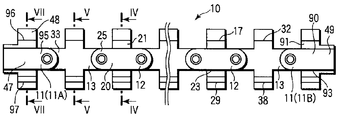
- the top view which shows the bending tube which concerns on 1st Embodiment.
- the perspective view which shows the connection state of the 1st node ring and 2nd node ring which concern on 1st Embodiment.
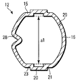
- FIG. 4 is a sectional view taken along line IV-IV in FIG. 2.
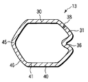
- FIG. 5 is a sectional view taken along line VV in FIG. 2.
- FIG. 6 is a sectional view taken along line VI-VI in FIG. 3.
- FIG. 3 is a sectional view taken along line VII-VII in FIG. 2.
- the flowchart which shows the manufacturing process of the bending tube which concerns on 1st Embodiment.
- FIG. 10B is an enlarged plan view showing a range 10B of FIG. 10A.
- the top view which shows the state after performing the 3rd hole drilling process of the 1st plate-shaped member which concerns on 1st Embodiment.
- the top view which shows the state after performing the step bending process of the 1st plate-shaped member which concerns on 1st Embodiment.
- FIG. 13B is a sectional view taken along line 13B-13B of FIG. 13A.
- the top view which shows the state after performing the 4th hole drilling process of the 2nd plate-shaped member which concerns on 1st Embodiment.
- the top view which shows the state after performing the burring process of the 2nd plate-shaped member which concerns on 1st Embodiment.
- FIG. 14C is a sectional view taken along line 14C-14C of FIG. 14B.
- the top view which shows the state after performing the 6th hole drilling process of the 2nd plate-shaped member which concerns on 1st Embodiment.
- the top view which shows the state after performing the 6th hole drilling process of the 2nd node-wheel preparation body which concerns on 1st Embodiment.
- the perspective view which shows the state after performing the overlapping process and burring expansion process of the bending tube which concern on 1st Embodiment.
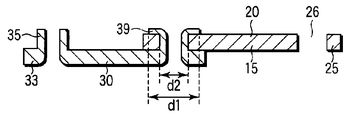
- Sectional drawing which shows the state at the time of the burring expansion process of the connection part of the 1st node ring and 2nd node ring which concern on 1st Embodiment.
- the top view which shows the state after performing the edge part cutting process of the bending tube which concerns on 1st Embodiment.
- the top view which shows the state after performing the bending process of the bending pipe which concerns on 1st Embodiment.
- FIG. 27 is a sectional view taken along line 27A-27A in FIG.
- FIG. 27 is a sectional view taken along line 27B-27B of FIG.
- FIG. 29 is a sectional view taken along line 29A-29A in FIG.
- FIG. 29 is a sectional view taken along line 29B-29B of FIG.
- Sectional drawing which shows the connection state of the 1st node ring and 2nd node ring which concern on the 8th modification of 1st Embodiment.
- FIG. 31 is a cross-sectional view taken along line 31A-31A of FIG.
- FIG. 31B is a sectional view taken along line 31B-31B of FIG. 30.
- FIG. 33 is a sectional view taken along line 33A-33A in FIG.
- FIG. 33 is a sectional view taken along line 33B-33B of FIG.
- the top view which shows the bending tube which concerns on the 2nd Embodiment of this invention.
- the perspective view which shows the both-ends node ring which concerns on the 3rd Embodiment of this invention.
- 36 is a sectional view taken along line 36-36 in FIG.
- the flowchart which shows the manufacturing method of the bending tube which concerns on the 4th Embodiment of this invention.
- FIG. 1 is a diagram showing a configuration of the endoscope 1 as a whole.
- the endoscope 1 includes an elongated insertion portion 2 that is inserted into a body cavity, and an operation portion 3 that is connected to the proximal end side of the insertion portion 2.
- the insertion portion 2 includes a long and flexible flexible tube 4, a bending portion 5 connected to the distal end side of the flexible tube 4, and a distal end rigid portion 6 connected to the distal end side of the bending portion 5.
- the operation unit 3 is provided with an operation knob 7 for performing a bending operation of the bending unit 5.
- the bending portion 5 includes a bending tube 10 and a flexible outer tube (not shown) such as a rubber material coated on the outer peripheral surface of the bending tube 10.
- FIG. 2 is a diagram showing a configuration of the bending tube 10.
- the bending tube 10 includes a both-end node ring 11 including a front end node ring 11 ⁇ / b> A connected to the distal end rigid portion 6 and a rear end node ring 11 ⁇ / b> B connected to the flexible tube 4. Is provided.
- two types of substantially annular node rings 12 and 13 (hereinafter referred to as a first node ring 12 and a second node ring 13) are arranged in the longitudinal direction of the insertion portion 2. They are arranged alternately.
- the first node ring 12 and the second node ring 13 are connected to each other so as to be rotatable.
- FIG. 3 is a diagram showing a connection state between the first node ring 12 and the second node ring 13.
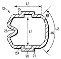
- the first node ring 12 includes a pair of planar first hinge portions 15 provided symmetrically to each other with respect to a central axis (longitudinal axis), and a first hinge portion 15. And a pair of first peripheral wall portions 16 having a cylindrical surface provided between them.
- a first ridge line 17 is formed between the first hinge portion 15 and the first peripheral wall portion 16.
- FIG. 4 is a cross-sectional view taken along line IV-IV in FIG.
- the first hinge portion 15 has a length L ⁇ b> 1 in the circumferential direction of the first node ring 12.
- the first hinge portion 15 is provided on both sides of the first central plane portion 20 in the circumferential direction of the first elliptical first central plane portion 20 and the first node ring 12 (curved tube 10). And both side plane portions 21. Between the first central plane portion 20 and the first both side plane portions 21, an axial step portion 23 is formed over the entire length in the axial direction (longitudinal direction) of the first node ring 12.
- the first central flat portion 20 is arranged on the outer peripheral side by the thickness of the first node ring 12 with respect to the first both-side flat portion 21.
- the first side flat surface portions 21 of the first hinge portion 15 are separated from each other by a distance a1.
- first tongue piece portions 25 that are first connecting portions are provided at both ends of the first central plane portion 20 in the axial direction (longitudinal direction) of the first node ring 12. It has been.
- a through hole 26 is formed at the center of the first tongue piece 25.
- the first peripheral wall portion 16 is formed in a cylindrical surface shape, and has a peripheral length L2 that is a length along the circumferential direction of the cylindrical surface.
- a first wire receiver 28 is provided on one of the pair of first peripheral wall portions 16.
- the first wire receiver 28 is formed with two slits 27 along the circumferential direction in the first peripheral wall portion 16, and a belt-like portion between the two slits 27 protrudes in a C shape radially inward. It is formed by letting.
- the first wire receiver 28 is disposed 90 ° away from the first central plane portion 20 in the circumferential direction of the first node ring 12.
- the circumferential length L2 is a length that does not include the protruding portion of the first wire receiver 28.
- the first node ring 12 is formed by abutting the both end surfaces of the first node ring preparation body 12a and joining a part or all of the abutting part. Accordingly, the first joint portion 29 is formed in the first node ring 12 along the axial direction (longitudinal direction) of the first node ring 12.
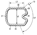
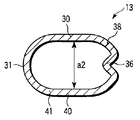
- the second node ring 13 is provided between a pair of second hinge portions 30 provided symmetrically with respect to the central axis (longitudinal axis) and the second hinge portion 30. And a pair of second peripheral wall portions 31.
- a second ridge line 32 is formed between the second hinge portion 30 and the second peripheral wall portion 31.
- the wall thickness of the second node ring 13 is substantially the same as the wall thickness of the first node ring 12.
- FIG. 5 is a cross-sectional view taken along line VV in FIG.
- the second hinge portion 30 includes a second center plane portion 40 having a substantially elliptical shape and a second center in the circumferential direction of the second node ring 13 (curved tube 10). And a second side flat surface portion 41 provided on both sides of the flat surface portion 40.
- the 2nd center plane part 40 and the 2nd both-sides plane part 41 are formed on the same plane.
- the second hinge portions 30 are formed in a planar shape and are separated from each other by a distance a2 (the second side flat portions 41 are separated from each other by a distance a2).
- the length L3 of the second hinge part 30 in the circumferential direction of the second node ring 13 is equal to the length L1 of the first hinge part 15 in the circumferential direction of the first node ring 12.
- second tongue pieces 33 as second connecting portions are provided at both ends of the second hinge portion 30 in the axial direction (longitudinal direction) of the second node ring 13. ing.
- a projecting portion 35 that projects toward the outer peripheral side of the second node ring 13 is formed at the center of the second tongue piece portion 33.
- the protrusion 35 is formed by, for example, burring.
- the second peripheral wall portion 31 is formed in a cylindrical surface shape.
- a circumferential length L4 that is a length along the circumferential direction of the cylindrical surface of the second circumferential wall portion 31 is equal to the circumferential length L2 of the first circumferential wall portion 16.
- the cross-sectional shape (second cross-sectional shape) of the second peripheral wall portion 31 cut perpendicularly to the axial direction of the curved tube 10 is a cross section of the first peripheral wall portion 16 cut perpendicularly to the axial direction of the curved tube 10 It is congruent with the shape (first cross-sectional shape).
- a second wire receiver 36 is provided on one of the pair of second peripheral wall portions 31.
- the second wire receiver 36 is formed by the same manufacturing method as the first wire receiver 28.
- the second wire receiver 36 is disposed 90 ° away from the second hinge portion 30 in the circumferential direction of the second node ring 13.
- the circumferential length S2 is a length that does not include the protruding portion of the second wire receiver 36.
- the second node ring 13 is formed by abutting the both end faces of the second node ring preparation body 13a and joining a part or all of the abutting part.
- a second joint 38 is formed in the second node ring 13 along the axial direction (longitudinal direction) of the second node ring 13.
- FIG. 6 is a cross-sectional view taken along line VI-VI in FIG.
- the first node ring 12 and the second ring 12 are connected. Are connected to each other in a rotatable manner.
- the distance a1 between the first side flat surface portions 21 of the first hinge portion 15 and the distance a2 between the second hinge portions 30 are equal, as shown in FIG.
- the fifteen first side plane portions 21 and the second hinge portion 30 are arranged on the same plane.
- the first central plane portion 20 disposed outside the first both-side plane portions 21 by the thickness of the first node ring 12 is first from the second hinge portion 30 (second central plane portion 40).
- the thickness of the node ring 12 and the second node ring 13 is arranged on the outer peripheral side of the bending tube 10. For this reason, in the state which the inner peripheral surface of the 1st center plane part 20 and the outer peripheral surface of the 2nd hinge part 30 (2nd center plane part 40) contact
- the first wire receiver 28 and the second wire receiver 36 are arranged 180 ° apart from each other in the circumferential direction of the bending tube 10. .
- the bending tube 10 is bent in two directions by the operation wires inserted through the first wire receiver 28 and the second wire receiver 36. In the present embodiment, the bending tube 10 is bent in two directions, but may be bent in four directions.
- the angle from the first hinge portion 15 to the first joint portion 29 in the circumferential direction of the bending tube 10 is the second hinge.
- the angle from the portion 30 to the second joint portion 38 is substantially the same.
- the both-end nodal ring 11 includes a pair of both-end node ring hinge portions 47 provided symmetrically with respect to the central axis, and a pair of both-end node ring hinge portions 47 provided between the both-end node ring hinge portions 47.
- Both end nodal ring ridge lines 96 are formed between the both end hinge portions 47 and the both end nodal ring peripheral wall portions 48.
- the both-end node ring hinges 47 are provided on both sides of the both-end node ring center plane part 90 and the both-end node ring center plane part 90 in the circumferential direction of the both-end node ring 11 (bending tube 10). And an axial step part 93 formed between the both-end node ring central plane part 90 and the both-end node ring side plane parts 91. That is, the both-end nodal ring hinge portion 47 has substantially the same configuration as the first hinge portion 15 of the first nodal ring 12.
- both-end node ring hinge portion 47 of the both-end node ring 11 the both-end node ring is connected only to one end portion of the both-end node ring center plane portion 90 in the axial direction (longitudinal direction) of the both-end node ring 11.
- Both end nodal ring tongue portions 95 are provided.
- the both-end nodal ring tongue portion 95 has the same configuration as the first tongue piece portion 25, and a through hole 26 is formed in the center of the both-end nodal ring tongue portion 95.
- Both end node ring 11 and second node ring 13 are connected to each other by engaging through hole 26 of both end node ring tongue portion 95 with protrusion 35 of second tongue piece portion 33.
- a fitting portion 49 projects in a direction opposite to the both-end node ring tongue piece 95 at the end of the both-end node ring hinge portion 47 opposite to the side where the both-end nodal ring tongue portion 95 is disposed.
- the front end node ring 11 ⁇ / b> A is fitted to the distal end hard portion 6 at the fitting portion 49, and the rear end node ring 11 ⁇ / b> B is fitted to the flexible tube 4 at the fitting portion 49.
- the both-end node ring peripheral wall portion 48 has substantially the same configuration as the first peripheral wall portion 16 of the first node ring 12, and is formed in a cylindrical surface shape. However, the first wire receiver 28 is not provided on the both-end node ring peripheral wall portion 48. In addition, the both-end node ring 11 is formed with both-end node ring joints 97 as in the case of the first node ring 12.
- FIG. 8 is a flowchart showing a manufacturing process of the bending tube 10.
- steps S101 to S104 the metal first plate-like member 51 is processed to form both-end nodal ring preparations 11a that form both-end nodal rings 11, and the first nodal ring 12.
- a first node ring preparation body 12a is formed.
- steps S101 to S104 will be described. Steps S101 to S104 are performed by pressing with a mold.
- FIG. 9 is a view showing a state after the first hole machining step S101 of the first plate-like member 51 is performed. As shown in FIG. 9, through the first hole machining step S ⁇ b> 101, both end joint ring tongue portions 95 of both end node rings 11 and through holes 26 of the first tongue piece portions 25 of the first node ring 12 are formed. Is done.
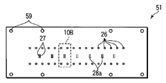
- FIG. 10A is a diagram showing a state after performing the second drilling step S102 of the first plate-like member 51.
- FIG. 10A the first wire receiving preparation portion 28a for forming the first wire receiver 28 of the first node ring 12 is formed by the second drilling step S102.
- FIG. 10B is an enlarged view of the range 10B of FIG. 10A.
- the first wire receiving preparation portion 28 a has two slits 27. After performing a bending step S112 for circularizing the first node ring preparation body 12a, which will be described later, a belt-like portion between the two slits 27 is formed in a C shape inwardly in the radial direction of the first node ring 12. By projecting, the first wire receiver 28 is formed.
- FIG. 11 is a diagram illustrating a state after the third hole machining step S103 of the first plate-like member 51 is performed.
- the both-end node ring preparation body 11 a that forms the both-end node ring 11 and the first node ring preparation body 12 a that forms the first node ring 12. It is formed.
- a gap 53 having an appropriate interval for arranging the second node ring preparation bodies 13a forming the second node ring 13 is formed.
- both-end node ring preparation body 11a and the first node ring preparation body 12a are formed with both end node ring tongue pieces 95, and the first node ring preparation body 12a is formed with a first tongue piece section 25.
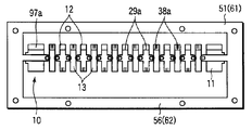
- both end portions of the belt-shaped first node ring preparation body 12 a in the circumferential direction of the bending tube 10 are connected to the first edge 56 by the first edge portion 55. ing.
- the end of the curved tube 10 in the axial direction (the direction of arrow B in FIG.
- FIG. 12 is a diagram illustrating a state after the step bending process S104 of the first plate-like member 51 is performed.
- the axial step part 93 is formed on the both-end node ring preparation body 11a
- the axial step part 23 is formed on the first node ring preparation body 12a.
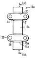
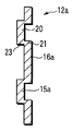
- FIG. 13A is a diagram showing the first node ring preparation body 12a after the step bending step S104 is performed
- FIG. 13B is a cross-sectional view taken along line 13B-13B in FIG. 13A. As shown in FIGS.
- the first node preparation 12a after the step bending step S104 includes a first hinge part preparation part 15a and a first peripheral wall part preparation part 16a. .
- the 1st hinge part preparation part 15a and the 1st surrounding wall part preparation part 16a after performing bending process S112 to circularize the 1st node ring preparation body 12a mentioned later, the 1st ridgeline 17 is performed.
- a first ridge line forming portion 17a is provided. Due to the axial step 23, a step is formed between the first central plane 20 and the first side plane 21 in the first hinge section 15 a of the first node preparation 12 a. .
- the step between the first central plane portion 20 and the first both side plane portions 21 in the axial step portion 23 is equal to the thickness of the first node ring preparation body 12a.
- a step portion 23b is formed between the edge 56 of the first plate-like member 51 and each of the first node ring preparation bodies 12a by step bending.
- the edge 56 of the first plate-like member 51 and the first central plane portion 20 are arranged on the same plane.
- both-end nodal ring center plane portion 90 and the both-end nodal ring side plane portions 91 are also formed in the both-end nodal ring hinge preparation portion 47 a of the both-end nodal ring preparation body 11 a by the axial stepped portion 93. .
- steps S105 to S108 the second plate member 61 made of metal is processed to form the second node ring preparation body 13a that forms the second node ring 13.
- steps S105 to S108 will be described. Steps S105 to S108 are performed by pressing with a mold.
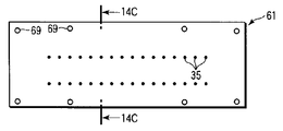
- FIG. 14A is a diagram illustrating a state after the fourth drilling step S105 of the second plate member 61 is performed
- FIGS. 14B and 14C are diagrams illustrating a state after the burring step S106 is performed. is there.
- the burring prepared hole 35a is formed by the fourth hole machining step S105.
- the protruding portion 35 is formed on the second tongue piece portion 33 of the second node ring 13 by the burring step S ⁇ b> 106.
- FIG. 15 is a diagram illustrating a state after the fifth hole machining step S107 of the second plate-shaped member 61 is performed.
- the 5th hole drilling process S107 forms the 2nd wire receiving preparation part 36a which forms the 2nd wire receiving 36 of the 2nd node ring 13.
- the second wire receiver preparation part 36 a has two slits 27 as with the first wire receiver preparation part 28 a, and the second wire receiver 36 is formed by the same manufacturing method as the first wire receiver 28. .
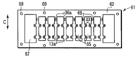
- FIG. 16 is a diagram illustrating a state after the sixth hole drilling step S108 of the second plate member 61 is performed.
- the 6th hole drilling process S108 forms the 2nd node ring preparation body 13a which forms the 2nd node ring 13.
- a gap 65 having an appropriate interval for arranging the first node ring preparation bodies 12a is formed.
- a gap 67 is formed between the second edge 62 of the second plate-like member 61 and the second node ring preparation body 13a with an appropriate interval for disposing the both-end node ring preparation bodies 11a.
- a second tongue piece 33 is formed in the second node ring preparation body 13a.
- both ends of the belt-shaped second node ring preparation body 13a in the circumferential direction of the bending tube 10 are connected to the second edge 62 by the second edge portion 68.
- Eight first positioning holes 69 are provided on the second edge 62 of the second plate member 61.
- the second node ring preparation body 13a is connected to the second edge 62 of the second plate-like member 61 only at one end portion by the second edge portion 68, and the other end portion is the second edge 62.
- the structure which is not connected with may be sufficient.
- FIG. 17 is a diagram illustrating the second node ring preparation body 13a in a state after the sixth drilling step S108 is performed.
- the second node ring preparation body 13a includes a second hinge part preparation part 30a and a second peripheral wall part preparation part 31a.
- the 2nd hinge part preparation part 30a and the 2nd surrounding wall part preparation part 31a After performing the bending process S112 which circularizes the 1st nodal ring preparation body 12a mentioned later, the 2nd ridgeline 32 is performed.
- a second ridge line forming portion 32a is provided.
- the second hinge part preparation unit 30 a includes a second central plane part 40 and second side plane parts 41.
- the 2nd center plane part 40 and the 2nd both-sides plane part 41 are arrange
- the overlapping step S109 and the burring expansion step S110 are performed to connect the first node ring preparation body 12a and the second node ring preparation body 13a. Similarly, the both-end node ring preparation body 11a and the second node ring preparation body 13a are connected.
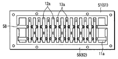
- FIG. 18A is a diagram showing a state after performing the overlapping step S109 and the burring expansion step S110.
- the second plate member 61 is arranged in a state where the protruding portion 35 of the second tongue piece portion 33 protrudes upward.
- the first plate member 51 is overlaid from the upper side of the second plate member 61 in a state where the first central plane portion 20 is arranged above the first both side plane portions 21.
- the first positioning hole 59 of the first plate-like member 51 and the second positioning hole 69 of the second plate-like member 61 are combined using a positioning mechanism or the like in the mold.
- the first plate member 51 and the second plate member 61 are overlapped. By overlapping at the position where the first positioning hole 59 of the first plate-like member 51 and the second positioning hole 69 of the second plate-like member 61 are combined, the both-end node ring preparation body 11a, the first The node ring preparation body 12a and the second node ring preparation body 13a are arranged at appropriate positions. Then, the protruding portion 35 of the second tongue piece portion 33 is inserted into the through hole 26 of the first tongue piece portion 25, and the through hole 26 and the protruding portion 35 are engaged with each other, so that the first node ring preparation is made. The body 12a and the second node ring preparation body 13a are connected.
- the projecting portion of the second tongue piece portion 33 is engaged with the through hole 26 of the both-end nodal ring tongue portion 95, so that the both-end nodal ring preparation body 11a and the second nodal ring preparation body 13a are connected. Is done.
- FIG. 18B is a diagram showing a state during the burring expansion step S110.
- the burring expansion step S110 is performed using the expansion punch 37.
- the retaining portion 39 is formed at the projecting tip of the projecting portion 35 by the burring expanding step S110.
- the diameter d1 of the retaining portion 39 is expanded larger than the diameter d2 of the through hole 26.
- FIG. 19 is a diagram illustrating a state after the edge portion cutting step S111 is performed.
- the first node ring preparation body 12a is made to be the first plate member by cutting the first edge portion 55 of the first plate member 51. Disconnected from first edge 56 of 51.
- the second node ring preparation body 13 a is separated from the second edge 62 of the second plate member 61 by cutting the second edge portion 68 of the second plate member 61.
- the both-end node ring preparation body 11 a remains connected to the first edge 56 of the first plate-like member 51 at both end edge portions 58.
- the edge portion cutting step S111 is performed by pressing with a mold.
- the bending step S112 is performed by performing O-bending on the first peripheral wall portion preparing portion 16a of the first node ring preparation body 12a by U-bending by pressing with a mold. The same bending process is also performed on the second peripheral wall part preparing portion 31a of the second node ring preparing body 13a and the both end node ring peripheral wall preparing parts 48a of the both end node ring preparing bodies 11a.
- FIG. 20 is a diagram showing a state after performing the bending step S112.
- the first node ring 12 is formed by the first node ring preparation body 12a
- the second node ring 13 is formed by the second node ring preparation body 13a.
- the both-end node ring 11 is formed by the both-end node ring preparation body 11a.
- the first node ring preparation body 12a is formed with a first abutting portion 29a with which both end surfaces abut against each other.
- both-end nodal ring abutment portions 97a are formed in the both-end nodal ring preparation body 11a.
- the first joint portion 29 is formed along the axial direction (longitudinal direction) of the first node ring 12 by joining a part or all of the first butting portion 29a by laser welding or the like.
- the both-end nodal ring joint portion 97 is formed along the longitudinal direction by joining a part or all of the both-end nodal ring abutting portions 97a by laser welding or the like.
- a second abutting portion 38a is formed in which both end faces abut against each other. By joining all or part of the second abutting portion 38 a, the second joining portion 38 is formed along the axial direction (longitudinal direction) of the second node ring 13.
- the first node ring preparation body 12 a is formed on the first plate member 51
- the second node ring preparation body 13 a is formed on the second plate member 61
- the first node ring preparation body 12a and the second node ring preparation body 13a are connected.
- the through hole 26 of the first tongue piece portion 25 of the first node ring preparation body 12a and the protruding portion 35 of the second tongue piece portion 33 of the second node ring preparation body 13a are engaged. .
- the first plate-like member 51 is formed with both-end node ring preparation bodies 11a, the through-holes 26 of the both-end node ring tongue pieces 95 of the both-end node ring preparation bodies 11a, and the second node ring preparation body 13a.
- the protrusion portion 35 of the second tongue piece portion 33 is engaged.
- the first node ring 12 is formed by bending the first peripheral wall portion preparing portion 16a of the first node ring preparing body 12a and the second peripheral wall portion preparing portion 31a of the second node ring preparing body 13a.
- a second node ring 13 is formed.
- the both-end node ring 11 is formed by bending the both-end node ring peripheral wall portion preparing portion 48a of the both-end node ring preparing body 11a.
- the bending tube 10 is formed without forming the both-end node ring 11 separately from the other node rings 12 and 13. Also, by connecting the first node ring preparation body 12a and the second node ring preparation body 13a before bending, the connection strength between the first node ring 12 and the second node ring 13 and Rotational characteristics are ensured. Similarly, the connection strength and rotation characteristics between the both-end node ring 11 and the second node ring 13 are also ensured.
- the distance a2 is equal.
- the 1st both-sides plane part 21 and the 2nd hinge part 30 of the 1st hinge part 15 are arrange
- the first central plane portion 20 disposed outside the first both side plane portions 21 by the thickness of the first node ring 12 is the second hinge portion 30 (second central plane portion 40). Further, the thickness of the first node ring 12 and the second node ring 13 is arranged on the outer peripheral side of the bending tube 10.
- the first inner planar surface of the first central plane portion 20 and the planar outer peripheral surface of the second hinge portion 30 are in contact with each other without a gap.
- the node ring 12 and the second node ring 13 are connected.
- the connection strength and the rotation characteristics between the first node ring and the second node ring preparation body 13a are obtained. Secured.
- the connection strength and rotation characteristics between the both-end node ring 11 and the second node ring 13 are also ensured.
- the first length which is the sum of the length L 1 of the first hinge portion 15 in the circumferential direction of the first node ring 12 and the circumferential length L 2 of the first peripheral wall portion 16 is the first.
- a second circumferential dimension which is the sum of the circumferential dimension S1 of the second hinge ring 30 and the length L3 of the second hinge ring 30 in the circumferential direction and the circumferential length L4 of the second circumferential wall 31. S2 is equal to each other.
- disconnected perpendicularly to the axial direction of the bending tube 10 of the 1st surrounding wall part 16 and the 2nd surrounding wall part 31 is congruent. It has become.
- a first node ring 12 and a second node ring 13 are formed.
- the through hole 26 of the first tongue piece portion 25 of the first node ring preparation body 12a and the second tongue piece portion 33 of the second node ring preparation body 13a After engaging the protrusion 35, the retaining portion 39 is formed at the protrusion tip of the protrusion 35 by expanding the burring.
- the connection strength and the rotation characteristics between the first node ring and the second node ring preparation body 13a are ensured.
- the connection strength and rotation characteristics between the both-end node ring 11 and the second node ring 13 are also ensured.
- the bending portion 5 of the endoscope 1 having the above configuration has the following effects. That is, in the bending tube 10 of the bending portion 5 according to the present embodiment, the length L1 of the first hinge portion 15 in the circumferential direction of the first node ring 12 and the circumferential length L2 of the first peripheral wall portion 16
- the first circumferential dimension S1 that is the sum, the length L3 of the second hinge ring 30 in the circumferential direction of the second node ring 13 and the circumferential length L4 of the second circumferential wall 31
- the circumferential dimension S2 of 2 is equal to each other.
- disconnected perpendicularly to the axial direction of the bending tube 10 of the 1st surrounding wall part 16 and the 2nd surrounding wall part 31 becomes congruent. ing.
- a first node ring 12 and a second node ring 13 can be provided.
- the both-end node ring 11 in which the distance between the both-end node ring side plane portions 91 of the both-end node ring hinge portion 47 is equal to the distance a1 and the distance a2. Therefore, the bending tube 10 is formed without forming both end node rings 11 separately from the other node rings 12 and 13. Thereby, the workability of forming and assembling the bending tube 10 can be improved, and the manufacturing cost can be suppressed.
- the bending step S112 is performed after the belt-shaped first node ring preparation body 12a and the belt-shaped second node ring preparation body 13a are connected.
- the connection strength and the rotation between the first node ring 12 and the second node ring 13 are reduced. Dynamic characteristics can be ensured.
- the connection strength and rotation characteristics between the both-end node ring 11 and the second node ring 13 can also be ensured.
- the distance a2 is equal.
- the 1st both-sides plane part 21 and the 2nd hinge part 30 of the 1st hinge part 15 are arrange
- the first central plane portion 20 disposed outside the first both side plane portions 21 by the thickness of the first node ring 12 is the second hinge portion 30 (second central plane portion 40). Further, the thickness of the first node ring 12 and the second node ring 13 is arranged on the outer peripheral side of the bending tube 10.
- the first inner planar surface of the first central plane portion 20 and the planar outer peripheral surface of the second hinge portion 30 are in contact with each other without a gap.
- the node ring 12 and the second node ring 13 are connected.
- the connection strength and the rotation characteristics between the first node ring 12 and the second node ring 13 are ensured. can do.
- the connection strength and rotation characteristics between the both-end node ring 11 and the second node ring 13 can also be ensured.
- the through hole 26 of the first tongue piece portion 25 of the first node ring preparation body 12a and the second tongue piece portion 33 of the second node ring preparation body 13a After engaging the protrusion 35, the retaining portion 39 is formed at the protrusion tip of the protrusion 35 by expanding the burring.
- the retaining portion 39 it is possible to ensure the connection strength and rotation characteristics between the first node ring and the second node ring preparation body 13a. Similarly, the connection strength and rotation characteristics between the both-end node ring 11 and the second node ring 13 can also be ensured.
- first to fifth modifications of the first embodiment of the present invention will be described with reference to FIGS. 21A to 25B.
- the configuration of the first embodiment is modified as follows.
- symbol is attached
- the both-end node ring 11 is the first except that a fitting portion 49 is provided at one end in the axial direction (longitudinal direction) of the bending tube 10. Since the configuration is substantially the same as that of the node ring 12, the description thereof is omitted.
- FIG. 21A is a diagram showing a first node ring 12 according to a first modification of the first embodiment
- FIG. 21B is a diagram showing a second node ring according to a second modification.
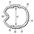
- a distance a1 between the first both-side flat surface portion 21 of the first hinge portion 15 from the first embodiment is set.
- the length L1 of the first hinge portion 15 in the circumferential direction of the first node ring 12 is shortened, and the circumferential length L2 of the first peripheral wall portion 16 is extended.
- FIG. 21A is a diagram showing a first node ring 12 according to a first modification of the first embodiment
- FIG. 21B is a diagram showing a second node ring according to a second modification.
- a distance a ⁇ b> 2 between the first embodiment (see FIG. 5) and the second hinge part 30 (second both side flat part 41) is set.
- the length L3 of the second hinge portion 30 in the circumferential direction of the second node ring 13 is shortened, and the circumferential length L4 of the second peripheral wall portion 31 is extended.
- the distance a ⁇ b> 2 between the second hinge parts 30 is equal to the distance a ⁇ b> 1 between the first central plane parts 21 of the first hinge part 15.
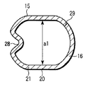
- FIG. 22A is a diagram showing a first node ring 12 of a second modification of the first embodiment
- FIG. 22B is a diagram showing a second node ring of the second modification.
- a distance a1 between the first central plane portion 21 of the first hinge portion 15 from the first embodiment is set.
- the length L1 of the first hinge portion 15 in the circumferential direction of the first node ring 12 is extended, and the peripheral length L2 of the first peripheral wall portion 16 is shortened.
- a distance a ⁇ b> 2 between the first embodiment see FIG.
- the second hinge part 30 (second both-side flat part 41) is set.
- the length L3 of the second hinge portion 30 in the circumferential direction of the second node ring 13 is extended, and the peripheral length L4 of the second peripheral wall portion 31 is shortened.
- the distance a ⁇ b> 2 between the second hinge parts 30 is equal to the distance a ⁇ b> 1 between the first central plane parts 21 of the first hinge part 15.
- the first is the sum of the length L1 of the first hinge portion 15 in the circumferential direction of the first node ring 12 and the circumferential length L2 of the first peripheral wall portion 16.
- a second circumferential dimension which is the sum of the circumferential dimension S1 of the second hinge ring 30 and the length L3 of the second hinge ring 30 in the circumferential direction and the circumferential length L4 of the second circumferential wall 31. It is only necessary that S2 is equal to each other. That is, if the first circumferential dimension S1 and the second circumferential dimension S2 are the same, the length L1 of the first hinge portion 15 in the circumferential direction of the first node ring 12 as shown in FIG. 22A.
- the length L3 in the circumferential direction of the second node ring 13 of the second hinge portion 30 may be extended as shown in FIG. 22B.
- the length L1 of the first hinge portion 15 in the circumferential direction of the first node ring 12 and the length L2 of the first peripheral wall portion 16 are the second node ring of the second hinge portion 30, respectively. 13 is not equal to the length L3 in the circumferential direction and the circumferential length L4 of the second peripheral wall portion 31.
- the distance a1 between the first side plane portions 21 of the first hinge portion 15 is equal to the distance a2 between the second hinge portions 30.
- the first central plane portion 20 of the first hinge portion 15 has the first node ring 12 and the second central portion 20 than the second hinge portion 30 (second central plane portion 40).
- the thickness of the second node ring 13 is arranged on the outer peripheral side of the bending tube 10.
- the first node ring 12 and the second ring 12 are in contact with each other without any gap between the inner peripheral surface of the first central plane portion 20 and the outer peripheral surface of the second hinge portion 30 (second central plane portion 40).
- the node ring 13 is connected.
- the first circumferential dimension S1 and the second circumferential dimension S2 are the same, the length in the circumferential direction of the first node ring 12 of the first hinge portion 15 as shown in FIG. 22A.
- L1 may be extended and the length L3 in the circumferential direction of the second node ring 13 of the second hinge portion 30 may be shortened as shown in FIG. 21B.
- FIG. 23A is a diagram showing a first node ring 12 of a third modification of the first embodiment
- FIG. 23B is a diagram showing a second node ring 13 of the third modification.
- a distance a1 between the first both-side flat surface portion 21 of the first hinge portion 15 from the first embodiment is set. It is shortened.
- the distance a2 between the second hinge portions 30 (second side plane portions 41) of the second node ring 13 is the distance between the first side plane portions 21. It is shortened to be equal to a1.
- FIG. 24A is a diagram showing the first node ring 12 of the fourth modification example of the first embodiment
- FIG. 24B is a diagram showing the second node ring 13 of the fourth modification example.
- the distance a1 between the first side plane portions 21 of the first hinge portion 15 is extended from the first embodiment (see FIG. 4). is doing.
- the distance a2 between the second hinge portions 30 (second side plane portions 41) of the second node ring 13 is the distance between the first side plane portions 21. It is extended to be equal to a1.
- FIG. 25A is a diagram showing a first node ring 12 of a fifth modification of the first embodiment
- FIG. 25B is a diagram showing a second node ring of the fifth modification.
- the first peripheral wall portion 16 is formed in a cylindrical surface shape (see FIG. 4), whereas, as shown in FIG. In one node ring 12, the first peripheral wall portion 16 includes a cylindrical surface portion 45 and a flat surface portion 46 provided between the first hinge portion 15 and the cylindrical surface portion 45.
- the second peripheral wall portion 31 is also composed of a cylindrical surface portion 45 and a flat surface portion 46 provided between the second hinge portion 30 and the cylindrical surface portion 45.
- the distance a1 between the first side plane portions 21 of the first hinge portion 15 is between the second hinge portions 30 (second side plane portions 41). It is equal to the distance a2.
- the first central plane portion 20 of the first hinge portion 15 has the first node ring 12 and the second second portion more than the second hinge portion 30 (second central plane portion 40).
- the thickness of the node ring 13 is arranged on the outer peripheral side of the bending tube 10. For this reason, the first node ring 12 and the second node are in a state where the planar inner peripheral surface of the first central planar portion 20 and the planar outer peripheral surface of the second central planar portion 40 are in contact with each other without a gap.
- the wheel 13 is connected.
- the sectional shape (second sectional shape) may be modified.
- the first circumferential dimension S1 that is the sum of the length L1 of the first hinge portion 15 in the circumferential direction of the first node ring 12 and the circumferential length L2 of the first circumferential wall portion 16; If the second circumferential dimension S2 which is the sum of the circumferential length L3 of the second node ring 13 of the hinge portion 30 and the circumferential length L4 of the second circumferential wall portion 31 is equal to each other Good.
- the configuration of the first embodiment is modified as follows.
- symbol is attached
- the both-end node ring 11 is substantially the same as the first node ring 12 except that a fitting portion 49 is provided at one end in the axial direction of the bending tube 10. Since the configuration is the same, the description thereof is omitted.
- FIG. 26 is a diagram illustrating a connection state of the first node ring 12 and the second node ring 13 according to a sixth modification of the first embodiment.
- 27A is a sectional view taken along line 27A-27A in FIG. 26
- FIG. 27B is a sectional view taken along line 27B-27B in FIG.
- the first node ring 12 includes a pair of planar first hinge portions 15 provided symmetrically with respect to a central axis (longitudinal axis), and a first hinge portion. 15 and a pair of first circumferential wall portions 16 having a cylindrical surface shape provided between the two.
- the first hinge portion 15 includes a first central plane portion 20 and first both side plane portions provided on both sides of the first central plane portion 20 in the circumferential direction of the first node ring 12 (bending tube 10). 21.
- the first side flat surface portions 21 of the first hinge portion 15 are separated from each other by a distance a1.
- An axial step portion 23 is formed between the first central plane portion 20 and the first both side plane portions 21.
- the first central flat portion 20 is arranged on the outer peripheral side by the thickness of the first node ring 12 with respect to the first both-side flat portion 21.
- first tongue pieces 25 are provided at both ends of the first central plane portion 20.
- a projecting portion 35 that projects toward the inner peripheral side of the first node ring 12 is formed at the center of the first tongue piece portion 25.
- the protrusion 35 is formed by, for example, burring.
- the second node ring 13 is formed between a pair of second hinge portions 30 provided symmetrically with respect to the central axis (longitudinal axis) and the second hinge portion 30. And a pair of second peripheral wall portions 31 provided to each other.
- the second hinge portion 30 includes a second center plane portion 40 and second side plane portions provided on both sides of the second center plane portion 40 in the circumferential direction of the second node ring 13 (bending tube 10). 41. In this modification, the second central plane part 40 and the second both side plane parts 41 are formed on the same plane.
- the second hinge portion 30 is formed in a planar shape, and the second hinge portions 30 are separated from each other by a distance a2 (the second side flat portions 41 are separated from each other by a distance a2).
- a distance a ⁇ b> 2 between the second hinge portions 30 is equal to a distance a ⁇ b> 1 between the first side flat surface portions 21 of the first hinge portion 15.
- a second tongue piece portion 33 is provided at both ends of the second hinge portion 30 in the axial direction (longitudinal direction) of the second node ring 13.
- a through hole 26 is formed at the center of the second tongue piece 33.
- the first node ring 12 and the second node ring 13 can be rotated with each other by the engagement between the protruding portion 35 of the first tongue piece portion 25 and the through hole 26 of the second tongue piece portion 33. Connected to At this time, since the distance a1 between the first side plane portions 21 of the first hinge section 15 and the distance a2 between the second hinge sections 30 are equal, the first side plane sections 21 and the second hinges.
- the parts 30 are arranged on the same plane.
- the first central plane portion 20 disposed outside the first both-side plane portions 21 by the thickness of the first node ring 12 is first from the second hinge portion 30 (second central plane portion 40).
- the thickness of the node ring 12 and the second node ring 13 is arranged on the outer peripheral side of the bending tube 10.
- first node ring 12 and the second node ring 13 are connected in a state in which the inner peripheral surface of the first central plane part 20 and the outer peripheral surface of the second central plane part 40 are in contact with each other without a gap. ing.
- a retaining portion 39 is formed in the projecting portion 35 to prevent the engagement between the through hole 26 and the projecting portion 35 from being released.
- FIG. 28 is a diagram illustrating a connection state of the first node ring 12 and the second node ring 13 according to a seventh modification of the first embodiment.
- 29A is a sectional view taken along line 29A-29A in FIG. 28
- FIG. 29B is a sectional view taken along line 29B-29B in FIG.
- the first node ring 12 is formed between a pair of first hinge portions 15 provided symmetrically with respect to a central axis (longitudinal axis) and the first hinge portions 15. And a pair of first peripheral wall portions 16 having a cylindrical surface shape.
- the first hinge portion 15 includes a first central plane portion 20 and first both side plane portions provided on both sides of the first central plane portion 20 in the circumferential direction of the first node ring 12 (bending tube 10). 21.
- the first central plane portion 20 and the first both side plane portions 21 are formed on the same plane. Therefore, the first hinge portion 15 is formed in a planar shape, and the first hinge portions 15 are separated from each other by a distance a1 (the first both side planar portions 21 are separated from each other by a distance a1).
- first tongue pieces 25 are provided at both ends of the first hinge portion 15.
- a through hole 26 is formed at the center of the first tongue piece 25.
- the second node ring 13 is formed between a pair of second hinge portions 30 provided symmetrically with respect to the central axis (longitudinal axis) and the second hinge portion 30. And a pair of second peripheral wall portions 31 provided to each other.
- the second hinge portion 30 includes a second center plane portion 40 and second side plane portions provided on both sides of the second center plane portion 40 in the circumferential direction of the second node ring 13 (bending tube 10). 41.
- the second side flat surface portions 41 of the second hinge portion 30 are separated from each other by a distance a2.
- the distance a ⁇ b> 2 is equal to the distance a ⁇ b> 1 between the first hinge portions 15 (the first side flat surface portions 21).
- An axial step portion 43 is formed between the second central plane portion 40 and the second both side plane portions 41.
- the second central plane portion 40 is disposed on the inner peripheral side of the second node ring 13 by the thickness of the second node ring 13 from the second both side plane portions 41.
- a second tongue piece portion 33 is provided at both ends of the second side flat surface portion 40 in the axial direction (longitudinal direction) of the second node ring 13.
- a projecting portion 35 that projects toward the outer peripheral side of the second node ring 13 is formed at the center of the second tongue piece portion 33.
- the protrusion 35 is formed by, for example, burring.
- the first node ring 12 and the second node ring 13 can rotate with respect to each other.
- the second side planes of the second hinge part 30 are the same.
- the part 41 and the first hinge part 15 (first both side plane part 21) are arranged on the same plane.
- the second central plane part 40 disposed on the inner side of the second both side plane parts 41 by the thickness of the second node ring 13 is first from the first hinge part 15 (first central plane part 20).
- the thickness of the node ring 12 and the second node ring 13 is arranged on the inner peripheral side of the bending tube 10. Therefore, the first node ring 12 and the second node ring 13 are connected in a state in which the inner peripheral surface of the first central plane portion 20 and the outer peripheral surface of the second central plane portion 40 are in contact with each other without a gap. Has been.
- a retaining portion 39 is formed in the projecting portion 35 to prevent the engagement between the through hole 26 and the projecting portion 35 from being released.
- FIG. 30 is a diagram illustrating a connection state between the first node ring 12 and the second node ring 13 according to an eighth modification of the first embodiment.
- 31A is a sectional view taken along line 31A-31A in FIG. 30, and
- FIG. 31B is a sectional view taken along line 31B-31B in FIG.
- the first node ring 12 is formed between a pair of first hinge portions 15 provided symmetrically with respect to the central axis (longitudinal axis) and the first hinge portions 15. And a pair of first peripheral wall portions 16 having a cylindrical surface shape.
- the first hinge portion 15 includes a first central plane portion 20 and first both side plane portions provided on both sides of the first central plane portion 20 in the circumferential direction of the first node ring 12 (bending tube 10). 21.
- the first central plane portion 20 and the first both side plane portions 21 are formed on the same plane. Therefore, the first hinge portion 15 is formed in a planar shape, and the first hinge portions 15 are separated from each other by a distance a1 (the first both side planar portions 21 are separated from each other by a distance a1).
- first tongue pieces 25 are provided at both ends of the first hinge portion 15.
- a projecting portion 35 that projects toward the inner peripheral side of the first node ring 12 is formed at the center of the first tongue piece portion 25.
- the protrusion 35 is formed by, for example, burring.
- the second node ring 13 is formed between a pair of second hinge portions 30 provided symmetrically with respect to the central axis (longitudinal axis) and the second hinge portion 30. And a pair of second peripheral wall portions 31 provided to each other.
- the second hinge portion 30 includes a second center plane portion 40 and second side plane portions provided on both sides of the second center plane portion 40 in the circumferential direction of the second node ring 13 (bending tube 10). 41.
- the second side flat surface portions 41 of the second hinge portion 30 are separated from each other by a distance a2.
- the distance a ⁇ b> 2 is equal to the distance a ⁇ b> 1 between the first hinge portions 15 (the first side flat surface portions 21).
- An axial step portion 43 is formed between the second central plane portion 40 and the second both side plane portions 41.
- the second central plane portion 40 is disposed on the inner peripheral side by the thickness of the second node ring 13 with respect to the second side plane portion 41.
- second tongue pieces 33 are provided at both ends of the first flat portion 40.
- a through hole 26 is formed at the center of the second tongue piece 33.
- the first node ring 12 and the second node ring 13 can be rotated with each other by the engagement between the protruding portion 35 of the first tongue piece portion 25 and the through hole 26 of the second tongue piece portion 33.
- Both side plane portions 41 and the first hinge portion 15 are arranged on the same plane.
- the second central plane part 40 disposed on the inner side of the second both side plane parts 41 by the thickness of the second node ring 13 is first from the first hinge part 15 (first central plane part 20).
- the thickness of the node ring 12 and the second node ring 13 is arranged on the inner peripheral side of the bending tube 10. Therefore, the first node ring 12 and the second node ring 13 are connected in a state in which the inner peripheral surface of the first central plane portion 20 and the outer peripheral surface of the second central plane portion 40 are in contact with each other without a gap. Has been.
- a retaining portion 39 is formed in the projecting portion 35 to prevent the engagement between the through hole 26 and the projecting portion 35 from being released.
- FIG. 32 is a diagram illustrating a connection state between the first node ring and the second node ring according to the ninth modification of the first embodiment.
- 33A is a sectional view taken along line 33A-33A in FIG. 32
- FIG. 33B is a sectional view taken along line 33B-33B in FIG.
- the first node ring 12 is formed between a pair of first hinge portions 15 provided symmetrically with respect to the central axis (longitudinal axis) and the first hinge portions 15. And a pair of first peripheral wall portions 16 having a cylindrical surface shape.
- the first hinge portion 15 includes a first central plane portion 20 and first both side plane portions provided on both sides of the first central plane portion 20 in the circumferential direction of the first node ring 12 (bending tube 10). 21.
- the first side flat surface portions 21 of the first hinge portion 15 are separated from each other by a distance a1.
- An axial stepped portion (first axial stepped portion) 23 is formed between the first central plane portion 20 and the first both side plane portions 21.
- the step at the axial step 23 is half the thickness of the first node ring 12.
- first tongue pieces 25 are provided at both ends of the first central plane portion 20.
- a projecting portion 35 that projects toward the inner peripheral side of the first node ring 12 is formed at the center of the first tongue piece portion 25.
- the protrusion 35 is formed by, for example, burring.
- the second node ring 13 is formed between a pair of second hinge portions 30 provided symmetrically with respect to the central axis (longitudinal axis) and the second hinge portion 30. And a pair of second peripheral wall portions 31 provided to each other.
- the second hinge portion 30 includes a second center plane portion 40 and second side plane portions provided on both sides of the second center plane portion 40 in the circumferential direction of the second node ring 13 (bending tube 10). 41.
- the second side flat surface portions 41 of the second hinge portion 30 are separated from each other by a distance a2.
- the distance a2 is equal to the distance a1 between the first side plane portions 21.
- An axial stepped portion (second axial stepped portion) 43 is formed between the second central plane portion 40 and the second both side plane portions 41.
- the step at the axial step 43 is half the thickness of the second node ring 13.
- the second central plane portion 40 is arranged on the inner peripheral side by half the thickness of the second node ring 13 from the second both side plane portions 41.
- second tongue piece portions 33 are provided at both ends of the second central plane portion 40.
- a through hole 26 is formed at the center of the second tongue piece 33.
- the first node ring 12 and the second node ring 13 can be rotated with each other by the engagement between the protruding portion 35 of the first tongue piece portion 25 and the through hole 26 of the second tongue piece portion 33.
- the distance a1 between the first side plane portions 21 of the first hinge portion 15 and the distance a2 between the second side plane portions 41 of the second hinge portion 30 are equal to each other.
- Both side plane portions 21 and second side plane portions 41 are arranged on the same plane.
- the first step portion 23 and the step portion 43 in the axial direction cause the first central plane portion 20 to be disposed on the outer peripheral side by a half of the thickness of the first node ring 12 from the first both side plane portions 21.
- the second central plane portion 40 is arranged on the inner peripheral side by a half of the thickness of the second node ring 13 from the second both side plane portions 41. For this reason, the second central plane part 40 of the second hinge part 30 is thicker than the first central plane part 20 of the first hinge part 15 by the thickness of the first node ring 12 and the second node ring 13. It is arranged on the inner peripheral side of the bending tube 10. In other words, the first node ring 12 and the second node ring 13 are connected in a state where the inner peripheral surface of the first central plane portion 20 and the outer peripheral surface of the second central plane portion 40 are in contact with each other without a gap. ing. In addition, a retaining portion 39 is formed in the projecting portion 35 to prevent the engagement between the through hole 26 and the projecting portion 35 from being released.
- the axial step portion 23 has an outer periphery of the first central plane portion 20 of the first hinge portion 15 that is half the thickness of the first node ring 12 than the first both side plane portions 21.
- the axial step part 43 is formed so that the second central plane part 40 of the second hinge part 30 is thicker than the second side plane part 41 of the second node ring 13. It is formed so as to be arranged on the inner peripheral side by half.
- the second center plane portion 40 has the first node ring 12 and the second node ring from the first center plane portion 20. It is only necessary that the axial step portion 23 and the axial step portion 43 be formed so as to be disposed on the inner peripheral side of the bending tube 10 by a thickness of thirteen.
- the axial step portions 23 and 43 are provided on at least one of the first hinge portion 15 and the second hinge portion 30, and the first central plane portion 20 and the Steps are formed between the two side plane portions 21 and / or between the second central plane portion 40 and the second side plane portions 41.
- at least the first both-side flat surface portion 21 of the first hinge portion 15 and the second both-side flat surface portion 41 of the second hinge portion 30 are arranged on the same plane.
- the first central plane portion 20 of the first hinge portion 15 is only thicker than the second central plane portion 40 of the second hinge portion 30 by the thickness of the first node ring 12 and the second node ring 13. It is arranged on the outer peripheral side.
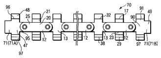
- FIG. 34 is a diagram showing the configuration of the bending tube 70.
- both end node rings 71 arranged at both ends of the bending tube 70 are provided between a pair of both end node ring hinge parts 47 provided symmetrically with respect to the central axis, and both end node ring hinge parts 47.
- a pair of both-end nodal ring peripheral wall portions 48 provided.
- Both end nodal ring ridge lines 96 are formed between the both end hinge portions 47 and the both end nodal ring peripheral wall portions 48.
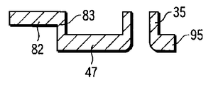
- the both-end node ring hinges 47 are provided on both sides of the both-end node ring center plane part 90 and the both-end node ring center plane part 90 in the circumferential direction of the both-end node ring 11 (bending tube 10). Have The both-end nodal ring center plane portion 90 and the both-end nodal ring side plane portions 91 are disposed on the same plane. That is, the both-end nodal ring hinge portion 47 has substantially the same configuration as the second hinge portion 30 (see FIGS. 3 and 5) of the second nodal ring 13 of the first embodiment.
- the both-end node ring tongue which is the both-end node ring connecting portion only at one end portion of the both-end node ring central plane portion 90 in the axial direction (longitudinal direction) of the both-end node ring 71.
- a piece 95 is provided.
- a projecting portion 35 is formed at the center of the both-end nodal ring tongue portion 95. The protruding portions 35 of the both-end nodal ring tongue portions 95 are engaged with the through holes 26 of the first tongue piece portion 25, whereby the both-end nodal rings 71 and the first nodal ring 12 are connected.
- a fitting portion 49 projects in a direction opposite to the both-end node ring tongue piece 95 at the end of the both-end node ring hinge portion 47 opposite to the side where the both-end nodal ring tongue portion 95 is disposed.
- the front end node ring 71 ⁇ / b> A is fitted to the distal end rigid portion 6 at the fitting portion 49, and the rear end node ring 71 ⁇ / b> B is fitted to the flexible tube 4 at the fitting portion 49.
- the both-end nodal ring peripheral wall portion 48 has substantially the same configuration as the second peripheral wall portion 31 of the second nodal ring 13 of the first embodiment, and is formed in a cylindrical surface shape.
- the second wire receiver 36 is not provided on the both-end node ring peripheral wall portion 48.
- the both-end node ring 71 is formed with a both-end node ring joint 97 similar to the second node ring 13.
- either one of the both end node rings 71 is connected to the second tongue piece portion 33 of the second node ring 13 and the other is connected to the first tongue piece portion 25 of the first node ring 12. It may be.
- the bending tube 70 is the same as that of the first embodiment except that the both-end nodal ring preparations 71a forming the both-end nodal rings 71 are formed on the second plate member 61 by steps S105 to S108 (see FIG. 8). It is formed by the same manufacturing method as that of the bending tube 10. Further, when either one of the both-end node rings 71 is connected to the second node ring 13 and the other is connected to the first node ring 12, both-end node rings connected to the second node ring 13 are connected.
- the prepared body 71a is formed on the first plate member 51 by steps S101 to S104, and the both-end node ring prepared body 71a connected to the first node ring 12 is formed on the second plate member 61 by steps S105 to S108. It is formed.
- both-end node ring 71 is an adjacent node ring adjacent to the both-end node ring 71 in the longitudinal direction, it is connected to both the first node ring 12 and the second node ring 13. It has a possible configuration. For this reason, in the bending tube 70, the arrangement of the first node ring 12 and the second node ring 13 and the axial length of the bending tube 70 can be changed.
- the bending portion 5 of the endoscope 1 having the above configuration has the following effects. That is, in the bending tube 70 of the bending portion 5 according to the present embodiment, the length L1 of the first hinge portion 15 in the circumferential direction of the first node ring 12 and the circumferential length L2 of the first peripheral wall portion 16
- the first circumferential dimension S1 which is the sum
- the length L3 of the second hinge portion 30 in the circumferential direction of the second node ring 13 and the circumferential length L4 of the second peripheral wall portion 31 are the sum. 2 are equal to each other in the circumferential dimension S2.
- disconnected perpendicularly to the axial direction of the bending tube 10 of the 1st surrounding wall part 16 and the 2nd surrounding wall part 31 is congruent. It has become.
- the first node ring 12 and the second node ring 13 can be provided.
- the both-end node ring 71 can be provided in which the distance between the both-end node ring side plane portions 91 of the both-end node ring hinge portion 47 is equal to the distance a1 and the distance a2. Therefore, the bending tube 70 is formed without forming both end node rings 71 separately from the other node rings 12 and 13. Thereby, the workability of forming and assembling the bending tube 70 can be improved, and the manufacturing cost can be suppressed.
- the distance a2 is equal.
- the 1st both-sides plane part 21 and the 2nd hinge part 30 of the 1st hinge part 15 are arrange
- the first central plane portion 20 disposed outside the first both side plane portions 21 by the thickness of the first node ring 12 is the second hinge portion 30 (second central plane portion 40). Further, the thickness of the first node ring 12 and the second node ring 13 is arranged on the outer peripheral side of the bending tube 10.
- the first node ring 12 and the second node are in a state where the planar inner peripheral surface of the first central planar portion 20 and the planar outer peripheral surface of the second central planar portion 40 are in contact with each other without a gap.
- the wheel 13 is connected.
- the connection strength and the rotation characteristics between the first node ring 12 and the second node ring 13 are ensured. can do.
- the connection strength and the rotation characteristics between the both-end node ring 71 and the adjacent node rings 12 and 13 can be secured.
- the through-hole 26 of the 1st tongue piece part 25 of the 1st node ring preparation body 12a and the 2nd tongue piece part 33 of the 2nd node ring preparation body 13a are used.
- the retaining portion 39 is formed at the protrusion tip of the protrusion 35 by expanding the burring.
- the both-end node ring 71 is an adjacent node ring adjacent to the both-end node ring 71 in the longitudinal direction, either the first node ring 12 or the second node ring 13 is used. Are also connectable. For this reason, in the bending tube 70, the arrangement of the first node ring 12 and the second node ring 13 and the length of the bending tube 70 in the longitudinal direction can be changed. Accordingly, it is possible to provide the bending tube 70 whose configuration is not limited by the length of the bending portion 5, the built-in object, or the like.
- FIG. 35 is a diagram showing a configuration of the both-end node ring 81 of the present embodiment.
- the both-end node rings 81 arranged at both ends of the bending tube are provided between a pair of both-end node ring hinge portions 47 provided symmetrically with respect to the central axis and the both-end node ring hinge portions 47.
- a pair of both-end nodal ring peripheral wall portions 48 are formed between the both end hinge portions 47 and the both end nodal ring peripheral wall portions 48.
- the both-end node ring hinges 47 are provided on both sides of the both-end node ring center plane part 90 and the both-end node ring center plane part 90 in the circumferential direction of the both-end node ring 11 (bending tube 10). Have The both-end nodal ring center plane portion 90 and the both-end nodal ring side plane portions 91 are disposed on the same plane. That is, the both-end nodal ring hinge portion 47 has substantially the same configuration as the second hinge portion 30 (see FIGS. 3 and 5) of the second nodal ring 13 of the first embodiment.
- both-end node ring tongues that are both-end node ring connection portions only at one end portion of the both-end node ring hinge portion 47 in the axial direction (longitudinal direction) of the both-end node ring 81.
- a portion 95 is provided.
- a projecting portion 35 is formed at the center of the both-end nodal ring tongue portion 95. The projecting portion 35 of the both-end nodal ring tongue portion 95 engages with the through hole 26 of the first tongue piece portion 25, thereby connecting the both-end nodal ring 81 and the first nodal ring 12.
- Both end node ring peripheral wall portions 48 have substantially the same configuration as the second peripheral wall portion 31 of the second node ring 13 of the first embodiment, and are formed in a cylindrical surface shape.
- the second wire receiver 36 is not provided on the both-end node ring peripheral wall portion 48.
- the both-end node ring 71 is formed with a both-end node ring joint 97 similar to the second node ring 13.
- a pair of fitting portions (protruding fitting portions) 82 are provided on the opposite side of the both-end node ring hinge portion 47 from the side where the both-end node ring tongue portion 95 is disposed. It is projecting toward.
- the fitting portions 82 are arranged approximately 180 ° apart from each other in the circumferential direction of the both-end node ring 81.
- the front end node ring 81 ⁇ / b> A is fitted to the distal end hard portion 6 at the fitting portion 82, and the rear end node ring 81 ⁇ / b> B is fitted to the flexible tube 4 at the fitting portion 82.
- 36A is a sectional view taken along line 36A-36A of FIG. As shown in FIGS.
- a fitting step portion (circumferential fitting step portion) 83 is provided between the both-end node ring hinge portion 47 and the fitting portion 82 along the circumferential direction of the both-end node ring 81. Is formed.
- the fitting portion 83 is disposed on the outer peripheral side of the both-end node ring 81 by the step of the fitting step portion 83 from the both-end node ring hinge portion 47.
- both-end node ring hinge portion 47 of the both-end node ring 81 has substantially the same configuration as the first hinge portion 15 (see FIGS. 3 and 4) of the first embodiment, and the both-end node ring center plane portion 90.
- An axial stepped portion 93 may be formed between the both-end nodal ring side plane portions 91.
- a fitting step part 83 is provided between the both-end node ring center plane part 90 and the fitting part 82.
- a fitting step portion 83 is formed between the both-end node ring hinge portion 47 of the both-end node ring 81 and the fitting portion 82.
- the bending portion 5 of the endoscope 1 having the above configuration has the following effects. That is, in the bending tube 10 of the bending portion 5 according to the present embodiment, the length L1 of the first hinge portion 15 in the circumferential direction of the first node ring 12 and the circumferential length L2 of the first peripheral wall portion 16
- the first circumferential dimension S1 that is the sum, the length L3 of the second hinge ring 30 in the circumferential direction of the second node ring 13 and the circumferential length L4 of the second circumferential wall 31
- the circumferential dimension S2 of 2 is equal to each other.
- disconnected perpendicularly to the axial direction of the bending tube 10 of the 1st surrounding wall part 16 and the 2nd surrounding wall part 31 is congruent. It has become.
- the first node ring 12 and the second node ring 13 can be provided.
- the both-end node ring 81 can be provided in which the distance between the both-end node ring side plane portions 91 of the both-end node ring hinge portion 47 is equal to the distance a1 and the distance a2. Therefore, the bending tube is formed without forming both end node rings 81 separately from the other node rings 12 and 13. Thereby, the workability of forming and assembling the bending tube 10 can be improved, and the manufacturing cost can be suppressed.
- the distance a1 between the first side plane portions 21 of the first hinge portion 15 and the distance a2 between the second hinge portions 30 (second side plane portions 41). are equal to each other, the first both-side flat surface portion 21 and the second hinge portion 30 of the first hinge portion 15 are arranged on the same plane.
- the first central plane portion 20 disposed outside the first both side plane portions 21 by the thickness of the first node ring is more than the second hinge portion 30 (second central plane portion 40).
- a thickness of the first node ring 12 and the second node ring 13 is arranged on the outer peripheral side of the bending tube 10.
- the first node ring 12 and the second node are in a state where the planar inner peripheral surface of the first central planar portion 20 and the planar outer peripheral surface of the second central planar portion 40 are in contact with each other without a gap.
- the wheel 13 is connected.
- the connection strength and the rotation characteristics between the first node ring 12 and the second node ring 13 are ensured. can do.
- the connection strength and the rotation characteristics between the both-end node ring 81 and the adjacent node rings 12 and 13 can be secured.
- the through hole 26 of the first tongue piece portion 25 of the first node ring preparation body 12a and the protruding portion of the second tongue piece portion 33 of the second node ring preparation body 13a After engaging 35, the retaining portion 39 is formed at the tip of the protruding portion 35 by expanding the burring.
- the retaining portion 39 it is possible to ensure the connection strength and rotation characteristics between the first node ring 12 and the second node ring 13. Similarly, the connection strength and the rotation characteristics between the both-end node ring 81 and the adjacent node rings 12 and 13 can be secured.
- a fitting step portion 83 is formed between the both-end node ring hinge portion 47 and the fitting portion 82 of the both-end node ring 81.
- FIG. 36B is a diagram showing a method for manufacturing the bending tube 10 according to the present embodiment.
- the first hole that forms the through hole 26 of the first tongue piece portion 25 of the first node ring 12 in the first plate member 51.
- Laser processing is used for the machining step S101, the second hole machining step S102 for forming the first wire receiving preparation portion 28a, and the third hole machining step S103 for forming the first node ring preparation body 12a and the both-end preparation body 11a. Done.
- the fifth hole forming step S107 for forming the second wire receiving preparation portion 36a of the second node ring 13 and the sixth forming the second node ring preparation body 13a are formed on the second plate-like member 61.
- the hole processing step S108 is also performed by laser processing.
- the edge portion cutting step S111 for cutting the first edge portion 58 of the first plate-like member 51 and the second edge portion 68 of the second plate-like member 61 is also performed by laser processing.
- the processing step S108 and the edge portion cutting step S111 are performed by laser processing. By not using a mold for these steps, the mold cost is not required, and the manufacturing cost is reduced.
- the bending portion 5 of the endoscope 1 having the above configuration has the following effects. That is, in the bending tube 10 of the bending portion 5 according to the present embodiment, the length L1 of the first hinge portion 15 in the circumferential direction of the first node ring 12 and the circumferential length L2 of the first peripheral wall portion 16
- the first circumferential dimension S1 that is the sum, the length L3 of the second hinge ring 30 in the circumferential direction of the second node ring 13 and the circumferential length L4 of the second circumferential wall 31
- the circumferential dimension S2 of 2 is equal to each other.
- disconnected perpendicularly to the axial direction of the bending tube 10 of the 1st surrounding wall part 16 and the 2nd surrounding wall part 31 is congruent. It has become.
- the first node ring 12 and the second node ring 13 can be provided.
- the both-end node ring 11 in which the distance between the both-end node ring side plane portions 91 of the both-end node ring hinge portion 47 is equal to the distance a1 and the distance a2. Therefore, the bending tube 10 is formed without forming both end node rings 11 separately from the other node rings 12 and 13. Thereby, the workability of forming and assembling the bending tube 10 can be improved, and the manufacturing cost can be suppressed.
- first node ring preparation body 12a and the belt-like second node ring preparation body 13a are connected, bending is performed.
- the connection strength and the rotation between the first node ring 12 and the second node ring 13 are reduced. Dynamic characteristics can be ensured.
- the connection strength and rotation characteristics between the both-end node ring 11 and the second node ring 13 can also be ensured.
- the first central plane portion 20 disposed outside the first both side plane portions 21 by the thickness of the first node ring is more than the second hinge portion 30 (second central plane portion 40).
- a thickness of the first node ring 12 and the second node ring 13 is arranged on the outer peripheral side of the bending tube 10.
- the first node ring 12 and the second node are in a state where the planar inner peripheral surface of the first central planar portion 20 and the planar outer peripheral surface of the second central planar portion 40 are in contact with each other without a gap.
- the wheel 13 is connected.
- the connection strength and the rotation characteristics between the first node ring and the second node ring preparation body 13a are obtained. Can be secured.
- the connection strength and rotation characteristics between the both-end node ring 11 and the second node ring 13 can also be ensured.
- the through hole 26 of the first tongue piece portion 25 of the first node ring preparation body 12a and the protruding portion of the second tongue piece portion 33 of the second node ring preparation body 13a After engaging 35, the retaining portion 39 is formed at the tip of the protruding portion 35 by expanding the burring.
- the first hole processing step S101, the second hole processing step S102, the third hole processing step S103, the fifth hole processing step S107, the sixth hole processing step S108, and the edge is performed by laser processing.
- the mold cost is not required, and the manufacturing cost can be reduced.
Landscapes
- Physics & Mathematics (AREA)
- Health & Medical Sciences (AREA)
- Life Sciences & Earth Sciences (AREA)
- Optics & Photonics (AREA)
- Surgery (AREA)
- Biomedical Technology (AREA)
- Animal Behavior & Ethology (AREA)
- Radiology & Medical Imaging (AREA)
- Nuclear Medicine, Radiotherapy & Molecular Imaging (AREA)
- Engineering & Computer Science (AREA)
- Biophysics (AREA)
- Heart & Thoracic Surgery (AREA)
- Medical Informatics (AREA)
- Molecular Biology (AREA)
- Pathology (AREA)
- General Health & Medical Sciences (AREA)
- Public Health (AREA)
- Veterinary Medicine (AREA)
- Astronomy & Astrophysics (AREA)
- General Physics & Mathematics (AREA)
- Endoscopes (AREA)
- Instruments For Viewing The Inside Of Hollow Bodies (AREA)
Abstract
Description
Claims (16)
- 第1の節輪(12)及び第2の節輪(13)の2種類の節輪(12,13)を長手方向について交互に回動可能に連結した湾曲管(10,70)を備える内視鏡湾曲部(5)において、
前記第1の節輪(12)は、
前記第2の節輪(13)との連結部である第1の連結部(25)を備える第1の中央平面部(20)と、周方向について前記第1の中央平面部(20)の両側に設けられる第1の両側平面部(21)とを備え、長手方向軸に対して互いに対称に配置される一対の第1のヒンジ部(15)を具備し、
前記第2の節輪(13)は、
前記第1の節輪(12)の前記第1の連結部(25)に連結される第2の連結部(33)を備える第2の中央平面部(40)と、周方向について前記第2の中央平面部(40)の両側に設けられ、前記第1のヒンジ部(15)の前記第1の両側平面部(21)と同一平面上に配置される第2の両側平面部(41)とを備え、長手方向軸に対して互いに対称に配置される一対の第2のヒンジ部(30)を具備し、
前記第1の節輪(12)の前記第1のヒンジ部(15)、又は、前記第2の節輪(13)の前記第2のヒンジ部(30)の少なくともいずれか一方は、前記第1の中央平面部(20)と前記第1の両側平面部(21)との間、及び/又は、前記第2の中央平面部(40)と前記第2の両側平面部(41)との間に、長手方向について前記第1の節輪(12)及び/又は前記第2の節輪(13)の全長にわたって設けられ、前記第1の中央平面部(20)を前記第2の中央平面部(40)より前記節輪(12,13)の肉厚だけ前記湾曲管(10,70)の外周側に配置する軸方向段差部(23,43)を備える内視鏡湾曲部(5)。 - 前記第1の節輪(12)は、
周方向について前記一対の第1のヒンジ部(15)の間にそれぞれが配置され、前記一対の第1のヒンジ部(15)とともに前記第1の節輪(12)の周方向についての寸法である第1の周方向寸法(S1)を構成する一対の第1の周壁部(16)と、
前記第1の節輪(12)を帯状に展開した第1の節輪準備体(12a)の両端の一部又は全部を接合して形成される第1の接合部(29)と、
を具備し、
前記第2の節輪(13)は、
周方向について前記一対の第2のヒンジ部(30)の間にそれぞれが配置され、前記一対の第2のヒンジ部(30)とともに前記第2の節輪(13)の周方向についての寸法であり、前記第1の周方向寸法(S1)と同一の寸法を有する第2の周方向寸法(S2)を構成する一対の第2の周壁部(31)と、
前記第2の節輪(13)を帯状に展開した第2の節輪準備体(13a)の両端の一部又は全部を接合して形成され、周方向について前記第1のヒンジ部(15)から前記第1の接合部(29)までの角度と略同一の角度だけ前記第2のヒンジ部(30)から離れて配置される第2の接合部(38)と、
を具備する請求項1の内視鏡湾曲部(5)。 - 前記第1の周壁部(16)は、長手方向に垂直に切断した断面形状である第1の断面形状を備え、
前記第2の周壁部(31)は、長手方向に垂直に切断した断面形状であり、前記第1の断面形状と合同の形状である第2の断面形状を備える請求項2の内視鏡湾曲部(5)。 - 前記第1の連結部(25)又は前記第2の連結部(33)の一方は、前記湾曲管(10,70)の内側又は外側に向けて突出した突出部(35)を備え、
前記第1の連結部(25)又は前記第2の連結部(33)の他方は、前記突出部(35)と対応する位置に設けられ、前記突出部(35)と係合する貫通孔(26)を備える請求項1の内視鏡湾曲部(5)。 - 前記突出部(35)は、突出先端に設けられ、前記貫通孔(26)の径以上に径が拡開される抜止め部(39)を備える請求項4の内視鏡湾曲部(5)。
- 前記軸方向段差部(23,43)は、
前記第1の中央平面部(20)を前記第1の両側平面部(21)より外周側に配置する第1の軸方向段差部(23)と、
前記第2の中央平面部(40)を前記第2の両側平面部(41)より内周側に配置する第2の軸方向段差部(43)と、
を備える請求項1の内視鏡湾曲部(5)。 - さらに前記湾曲管(10,70)の最先端に設けられ、先端硬性部(6)に連結される前端節輪(11A,71A,81A)と、前記湾曲管(10,70)の最基端に設けられ、可撓管(4)に連結される後端節輪(11B,71B,81B)とから構成される両端節輪(11,71,81)を具備し、
前記両端節輪(11,71,81)は、前記第1の節輪(12)又は前記第2の節輪(13)の中で長手方向について隣接する前記節輪(12,13)に連結される両端節輪連結部(95)を備える平面状の両端節輪ヒンジ部(47)を備える請求項1の内視鏡湾曲部(5)。 - 前記両端節輪(11,71,81)は、前記両端節輪ヒンジ部(47)の前記両端節輪連結部(95)が配置される側と反対側の部位に設けられ、前記先端硬性部(6)又は前記可撓管(4)と嵌合する嵌合部(49,82)を備える請求項7の内視鏡湾曲部(5)。
- 前記両端節輪(81)は、前記嵌合部(82)を前記両端節輪ヒンジ部(47)より外周側に配置する嵌合段差部(83)を備える請求項8の内視鏡湾曲部(5)。
- 前記嵌合部(82)は、前記両端節輪ヒンジ部(47)から前記両端節輪連結部(95)と反対側に向けて突設される突出嵌合部(82)を備え、
前記嵌合段差部(83)は、前記嵌合部(83)と前記両端節輪ヒンジ部(47)との間に周方向に沿って設けられる周方向嵌合段差部(83)を備える請求項9の内視鏡湾曲部(5)。 - 第1の節輪(12)及び第2の節輪(13)の2種類の節輪(12,13)を長手方向について交互に回動可能に連結した湾曲管(10,70)の製造方法において、
第1の板状部材(51)に、前記第1の節輪(12)を帯状に展開した第1の節輪準備体(12a)を、周方向について前記第1の節輪準備体(12a)の両端又は一端が前記第1の板状部材(51)の縁(56)に第1の縁さん部(55)で連結された状態で、前記第1の節輪準備体(12a)同士の間に前記第2の節輪(13)を帯状に展開した第2の節輪準備体(13a)が配置される隙間(53)を設けて所定の数だけ形成する工程(S103)と、
前記第1の板状部材(51)とは別部材の第2の板状部材(61)に、前記第2の節輪準備体(13a)を、周方向について前記第2の節輪準備体(13a)の両端又は一端が前記第2の板状部材(61)の縁(62)に第2の縁さん部(68)で連結された状態で、前記第2の節輪準備体(13a)同士の間に前記第1の節輪準備体(12a)が配置される隙間(65)を設けて所定の数だけ形成する工程(S108)と、
前記第1の節輪準備体(12a)に設けられる第1の連結部(25)、又は、前記第2の節輪準備体(13a)に設けられる第2の連結部(33)の一方に、バーリング加工により突出部(35)を形成する工程(S106)と、
前記第1の連結部(25)又は前記第2の連結部(33)の他方に、前記突出部(35)と係合する貫通孔(26)を形成する工程(S101)と、
前記第1の板状部材(51)と前記第2の板状部材(61)とを重ね合わせた状態で、前記突出部(35)と前記貫通孔(26)とを係合し、前記第1の節輪準備体(12a)と前記第2の節輪準備体(13a)とを連結する工程(S109)と、
前記第1の縁さん部(55)で前記第1の板状部材(51)の前記縁(56)と前記第1の節輪準備体(12a)との間を切り離し、前記第2の縁さん部(68)で前記第2の板状部材(61)の前記縁(62)と前記第2の節輪準備体(13a)との間を切り離す工程(S111)と、
前記第1の節輪準備体(12a)及び前記第2の節輪準備体(13a)を曲げ加工により円環化し、周方向について前記第1の節輪準備体(12a)及び前記第2の節輪準備体(13a)の両端の一部又は全部を接合する工程と(S112)、
を具備する湾曲管(10,70)の製造方法。 - 前記湾曲管(10,70)の最先端に設けられ、先端硬性部(6)に連結される前端節輪(11A,71A,81A)と、前記湾曲管(10,70)の最基端に設けられ、可撓管(4)に連結される後端節輪(11B,71B,81B)とから構成され、前記第1の節輪(12)又は前記第2の節輪(13)の中で長手方向について隣接する前記節輪(12,13)に連結される両端節輪連結部(95)を備える両端節輪(11,71,81)を形成する工程(S101,S103,S106,S108,S109,S112)をさらに具備し、
前記両端節輪(11,71,81)を形成する前記工程(S101,S103,S106,S108,S109,S112)は、
前記両端節輪(11,71,81)を帯状に展開した両端節輪準備体(11a,71a,81a)を、長手方向について前記両端節輪連結部(95)が設けられる側と反対側の端部が前記第1の板状部材(51)又は前記第2の板状部材(61)の前記縁(56,62)に両端縁さん部(58)で連結された状態で、前記第1の節輪準備体(12a)又は前記第2の節輪準備体(13a)の中で長手方向に隣接する前記節輪準備体(12a,13a)が配置される隙間(99)を設けて形成する段階(S103,S108)と、
前記両端節輪連結部(25,33)に、第1の連結部(25)又は第2の連結部(33)の中で前記両端節輪準備体(11a,71a,81a)の前記両端節輪連結部(95)が連結される前記連結部(25,33)に形成される前記突出部(33)又は前記貫通孔(26)と係合する前記突出部(33)又は前記貫通孔(26)を形成する段階(S101,S106)と、
前記両端節輪準備体(11a,71a,81a)を前記第1の節輪準備体(12a)又は前記第2の節輪準備体(13a)の中で長手方向に隣接する前記節輪準備体(12a,13a)に連結する段階(S109)と、
前記両端節輪準備体(11a,71a,81a)を曲げ加工により円環化し、周方向について前記両端節輪準備体(11a,71a,81a)の両端の一部又は全部を接合する段階(S112)と、
を備える請求項11に記載の湾曲管(10,70)の製造方法。 - 前記第1の節輪準備体(12a)に、前記第1の連結部(25)を備える第1の中央平面部(20)と、周方向について前記第1の中央平面部(20)の両側に設けられる第1の両側平面部(21)とを備え、前記第1の節輪(12)において長手方向軸に対して互いに対称に配置される一対の第1のヒンジ部(15)を構成する第1のヒンジ部準備部(15a)を形成する工程(S103)と、
前記第2の節輪準備体(13a)に、前記第2の連結部(33)を備える第2の中央平面部(40)と、周方向について前記第2の中央平面部(40)の両側に設けられ、前記第1のヒンジ部準備部(15a)の前記第1の両側平面部(21)と同一平面上に配置される第2の両側平面部(41)とを備え、前記第2の節輪(13)において長手方向軸に対して互いに対称に配置される一対の第2のヒンジ部(30)を構成する第2のヒンジ部準備部(30a)を形成する工程(S108)と、
前記第1のヒンジ部準備部(15a)、又は、前記第2のヒンジ部準備部(30a)の少なくともいずれか一方に、前記第1の節輪準備体(12a)及び前記第2の第2の節輪準備体(13a)の円環化後に前記第1の中央平面部(20)を前記第2の中央平面部(40)より前記節輪(12,13)の肉厚だけ前記湾曲管(10,70)の外周側に配置する軸方向段差部(23,43)を、前記第1の中央平面部(20)と前記第1の両側平面部(21)との間、及び/又は、前記第2の中央平面部(40)と前記第2の両側平面部(41)との間に、長手方向について前記第1の節輪準備体(12a)及び/又は前記第2の節輪準備体(13a)の全長にわたって形成する工程(S104)と、
をさらに具備する請求項11の湾曲管(10,70)の製造方法。 - 前記第1の節輪準備体(12a)を形成する前記工程(S103)は、前記第1の板状部材(51)に金型でのプレス加工により前記第1の節輪準備体(12a)を形成する段階(S103)を備え、
前記第2の節輪準備体(13a)を形成する前記工程(S108)は、前記第2の板状部材(61)に金型でのプレス加工により前記第2の節輪準備体(13a)を形成する段階(S108)を備え、
前記突出部(35)を形成する前記工程(S106)は、前記第1の連結部(25)又は前記第2の連結部(33)の一方に、金型でのプレス加工により前記突出部(35)を形成する段階(S106)を備え、
前記貫通孔(26)を形成する前記工程(S101)は、前記第1の連結部(25)又は前記第2の連結部(33)の他方に、金型でのプレス加工により前記貫通孔(26)を形成する段階(S101)を備え、
前記第1の節輪準備体(12a)と前記第2の節輪準備体(13a)とを連結する前記工程(S109)は、金型でのプレス加工により前記第1の節輪準備体(12a)と前記第2の節輪準備体(13a)とを連結する段階(S109)を備え、
前記第1の板状部材(51)の前記縁(56)と前記第1の節輪準備体(12a)との間、及び、前記前記第2の板状部材(61)の前記縁(62)と前記第2の節輪準備体(13a)との間を切り離す前記工程(S111)は、金型でのプレス加工により、前記第1の縁さん部(55)で前記第1の板状部材(51)の前記縁(56)と前記第1の節輪準備体(12a)との間を、前記第2の縁さん部(68)で前記第2の板状部材(61)の前記縁(62)と前記第2の節輪準備体(13a)との間を切り離す段階(S111)を備え、
前記第1の節輪準備体(12a)及び前記第2の節輪準備体(13a)を円環化する前記工程(S112)は、金型でのプレス加工により前記第1の節輪準備体(12a)及び前記第2の節輪準備体(13a)を円環化する段階(S112)を備える請求項11の湾曲管(10,70)の製造方法。 - 前記第1の節輪準備体(12a)を形成する前記工程(S103)は、前記第1の板状部材(51)にレーザー加工より前記第1の節輪準備体(12a)を形成する段階(S103)を備え、
前記第2の節輪準備体(13a)を形成する前記工程(S108)は、前記第2の板状部材(61)にレーザー加工により前記第2の節輪準備体(13a)を形成する段階(S108)を備え、
前記貫通孔(26)を形成する前記工程(S101)は、前記第1の連結部(25)又は前記第2の連結部(33)に、レーザー加工により前記貫通孔(26)を形成する段階(S101)を備え、
前記第1の板状部材(51)の前記縁(56)と前記第1の節輪準備体(12a)との間、及び、前記前記第2の板状部材(61)の前記縁(62)と前記第2の節輪準備体(13a)との間を切り離す前記工程(S111)は、レーザー加工により、前記第1の縁さん部(55)で前記第1の板状部材(51)の前記縁(56)と前記第1の節輪準備体(12a)との間を、前記第2の縁さん部(68)で前記第2の板状部材(61)の前記縁(62)と前記第2の節輪準備体(13a)との間を切り離す段階(S111)を備える請求項11の湾曲管(10,70)の製造方法。 - 前記突出部(35)の突出先端に、前記貫通孔(26)の径以上に径が拡開される抜止め部(39)を形成する工程(S110)をさらに具備する請求項11の湾曲管(10,70)の製造方法。
Priority Applications (3)
| Application Number | Priority Date | Filing Date | Title |
|---|---|---|---|
| CN201080017421.5A CN102405009B (zh) | 2009-04-21 | 2010-04-08 | 内窥镜弯曲部及弯曲管的制造方法 |
| DE112010001704T DE112010001704T8 (de) | 2009-04-21 | 2010-04-08 | Endoskopbiegeabschnitt und Herstellungsverfahren für eine Biegeröhre |
| US13/220,316 US8939899B2 (en) | 2009-04-21 | 2011-08-29 | Endoscope bending portion and manufacturing method of bending tube |
Applications Claiming Priority (2)
| Application Number | Priority Date | Filing Date | Title |
|---|---|---|---|
| JP2009-103163 | 2009-04-21 | ||
| JP2009103163A JP5404154B2 (ja) | 2009-04-21 | 2009-04-21 | 内視鏡湾曲部及び湾曲管の製造方法 |
Related Child Applications (1)
| Application Number | Title | Priority Date | Filing Date |
|---|---|---|---|
| US13/220,316 Continuation US8939899B2 (en) | 2009-04-21 | 2011-08-29 | Endoscope bending portion and manufacturing method of bending tube |
Publications (1)
| Publication Number | Publication Date |
|---|---|
| WO2010122902A1 true WO2010122902A1 (ja) | 2010-10-28 |
Family
ID=43011022
Family Applications (1)
| Application Number | Title | Priority Date | Filing Date |
|---|---|---|---|
| PCT/JP2010/056353 Ceased WO2010122902A1 (ja) | 2009-04-21 | 2010-04-08 | 内視鏡湾曲部及び湾曲管の製造方法 |
Country Status (5)
| Country | Link |
|---|---|
| US (1) | US8939899B2 (ja) |
| JP (1) | JP5404154B2 (ja) |
| CN (1) | CN102405009B (ja) |
| DE (1) | DE112010001704T8 (ja) |
| WO (1) | WO2010122902A1 (ja) |
Cited By (1)
| Publication number | Priority date | Publication date | Assignee | Title |
|---|---|---|---|---|
| WO2024053319A1 (ja) * | 2022-09-08 | 2024-03-14 | オリンパスメディカルシステムズ株式会社 | 内視鏡の湾曲管、内視鏡、内視鏡の湾曲管の製造方法及び挿入機器の湾曲管 |
Families Citing this family (11)
| Publication number | Priority date | Publication date | Assignee | Title |
|---|---|---|---|---|
| KR101911810B1 (ko) * | 2011-12-23 | 2018-10-26 | 삼성전자주식회사 | 내시경 장비에 구비되는 벤딩모듈 및 그 제조 방법 |
| CN103690140A (zh) * | 2014-01-10 | 2014-04-02 | 上海欧太医疗器械有限公司 | 内窥镜接节圈、内窥镜弯曲部及相应的内窥镜装置 |
| WO2016138443A2 (en) | 2015-02-26 | 2016-09-01 | Stryker Corporation | Surgical instrument with articulation region |
| EP3265160B1 (en) | 2015-03-02 | 2018-12-19 | Koninklijke Philips N.V. | Variable configuration bending neck for an articulating ultrasound probe |
| JP6785783B2 (ja) | 2015-03-02 | 2020-11-18 | コーニンクレッカ フィリップス エヌ ヴェKoninklijke Philips N.V. | 超音波プローブのための連結ネック及びネック形成方法 |
| CN107091261B (zh) * | 2017-02-14 | 2020-10-09 | 珠海普生医疗科技有限公司 | 一种蛇骨的加工方法 |
| CN208659304U (zh) * | 2018-01-02 | 2019-03-29 | 珠海嘉润医用影像科技有限公司 | 一种用于一次性内窥镜的弯曲部 |
| US11986257B2 (en) * | 2018-12-28 | 2024-05-21 | Auris Health, Inc. | Medical instrument with articulable segment |
| CN111714070B (zh) * | 2020-07-27 | 2025-01-07 | 湖南省华芯医疗器械有限公司 | 一种蛇骨组件及内窥镜 |
| US12543933B2 (en) | 2022-09-08 | 2026-02-10 | Olympus Medical Systems Corp. | Bending tube of endoscope, endoscope, and manufacturing method for bending tube of endoscope |
| CN118664347B (zh) * | 2024-08-23 | 2024-10-29 | 湖南省华芯医疗器械有限公司 | 一种主动弯曲段的加工方法及主动弯曲段 |
Citations (4)
| Publication number | Priority date | Publication date | Assignee | Title |
|---|---|---|---|---|
| JPS55164003U (ja) * | 1979-05-14 | 1980-11-25 | ||
| JPS6439701U (ja) * | 1987-09-03 | 1989-03-09 | ||
| JPH0282936A (ja) * | 1988-09-20 | 1990-03-23 | Toshiba Corp | 可撓連結体 |
| JP2007159636A (ja) * | 2005-12-09 | 2007-06-28 | Olympus Corp | 内視鏡挿入部及びその製造方法、並びに、内視鏡 |
Family Cites Families (10)
| Publication number | Priority date | Publication date | Assignee | Title |
|---|---|---|---|---|
| JPS6121042Y2 (ja) | 1979-04-20 | 1986-06-24 | ||
| JPS6121042A (ja) | 1984-07-10 | 1986-01-29 | 松下電工株式会社 | ごきぶりの防除装置 |
| JP2938486B2 (ja) * | 1989-12-28 | 1999-08-23 | 株式会社町田製作所 | 湾曲管およびその製造方法 |
| US5656011A (en) * | 1994-04-28 | 1997-08-12 | Epflex Feinwerktechnik Gmbh | Endoscope tube system |
| JP2005334050A (ja) * | 2004-05-24 | 2005-12-08 | Fujinon Corp | 内視鏡のアングル部 |
| JP4477519B2 (ja) * | 2005-02-14 | 2010-06-09 | オリンパス株式会社 | 内視鏡 |
| WO2007066436A1 (ja) | 2005-12-09 | 2007-06-14 | Olympus Corporation | 内視鏡挿入部及びその製造方法 |
| JP2007185314A (ja) * | 2006-01-12 | 2007-07-26 | Olympus Corp | 内視鏡湾曲管及びその製造方法、並びに、内視鏡 |
| JP2007190326A (ja) * | 2006-01-23 | 2007-08-02 | Olympus Corp | 内視鏡挿入部の製造方法 |
| JP2007252448A (ja) | 2006-03-22 | 2007-10-04 | Pentax Corp | 内視鏡の挿入部 |
-
2009
- 2009-04-21 JP JP2009103163A patent/JP5404154B2/ja active Active
-
2010
- 2010-04-08 WO PCT/JP2010/056353 patent/WO2010122902A1/ja not_active Ceased
- 2010-04-08 DE DE112010001704T patent/DE112010001704T8/de not_active Expired - Fee Related
- 2010-04-08 CN CN201080017421.5A patent/CN102405009B/zh active Active
-
2011
- 2011-08-29 US US13/220,316 patent/US8939899B2/en active Active
Patent Citations (4)
| Publication number | Priority date | Publication date | Assignee | Title |
|---|---|---|---|---|
| JPS55164003U (ja) * | 1979-05-14 | 1980-11-25 | ||
| JPS6439701U (ja) * | 1987-09-03 | 1989-03-09 | ||
| JPH0282936A (ja) * | 1988-09-20 | 1990-03-23 | Toshiba Corp | 可撓連結体 |
| JP2007159636A (ja) * | 2005-12-09 | 2007-06-28 | Olympus Corp | 内視鏡挿入部及びその製造方法、並びに、内視鏡 |
Cited By (1)
| Publication number | Priority date | Publication date | Assignee | Title |
|---|---|---|---|---|
| WO2024053319A1 (ja) * | 2022-09-08 | 2024-03-14 | オリンパスメディカルシステムズ株式会社 | 内視鏡の湾曲管、内視鏡、内視鏡の湾曲管の製造方法及び挿入機器の湾曲管 |
Also Published As
| Publication number | Publication date |
|---|---|
| CN102405009B (zh) | 2014-04-23 |
| JP5404154B2 (ja) | 2014-01-29 |
| US8939899B2 (en) | 2015-01-27 |
| US20110313251A1 (en) | 2011-12-22 |
| JP2010252859A (ja) | 2010-11-11 |
| DE112010001704T8 (de) | 2012-12-06 |
| CN102405009A (zh) | 2012-04-04 |
| DE112010001704T5 (de) | 2012-09-20 |
Similar Documents
| Publication | Publication Date | Title |
|---|---|---|
| JP5404154B2 (ja) | 内視鏡湾曲部及び湾曲管の製造方法 | |
| CN101677752B (zh) | 内窥镜弯曲部 | |
| JP2938486B2 (ja) | 湾曲管およびその製造方法 | |
| JP4454078B2 (ja) | 内視鏡の湾曲管およびその製造方法 | |
| CN103764008B (zh) | 弯曲部以及内窥镜 | |
| JP2003135381A (ja) | 湾曲管及びその製造方法 | |
| JP2009261587A (ja) | 内視鏡湾曲管とその製造方法及び内視鏡 | |
| JP2008193481A (ja) | 可とう導波管用接栓 | |
| KR200304313Y1 (ko) | 결합형 이중 반지 | |
| JP2001153115A (ja) | 鋼管の連結構造 | |
| JP2008095747A (ja) | 管体の屈曲部保護カバー | |
| JP2010154953A (ja) | 内視鏡湾曲部及び段付き節輪の製造方法 | |
| JP4855769B2 (ja) | 内視鏡挿入部及びその製造方法、並びに、内視鏡 | |
| JP2010121744A (ja) | 波付合成樹脂管およびその接続方法 | |
| JP5929858B2 (ja) | 巻型マフラーの製造方法 | |
| JP2003021294A (ja) | 組立式管体 | |
| JP2004236684A (ja) | 内視鏡用湾曲管および節輪の接続方法 | |
| JP2899952B2 (ja) | 組立て式管体 | |
| JP3723787B2 (ja) | セグメントの継手金具 | |
| CN117653001A (zh) | 内窥镜的弯曲管、内窥镜以及内窥镜的弯曲管的制造方法 | |
| CN100486056C (zh) | 同轴电缆密封环 | |
| JPH019522Y2 (ja) | ||
| JP2008256028A (ja) | 配管およびその製造方法 | |
| CN119997862A (zh) | 内窥镜的弯曲管、内窥镜、内窥镜的弯曲管的制造方法以及插入设备的弯曲管 | |
| JP4140037B2 (ja) | シールドトンネル用セグメント及び該セグメントを使用したシールドトンネル覆工 |
Legal Events
| Date | Code | Title | Description |
|---|---|---|---|
| WWE | Wipo information: entry into national phase |
Ref document number: 201080017421.5 Country of ref document: CN |
|
| 121 | Ep: the epo has been informed by wipo that ep was designated in this application |
Ref document number: 10766960 Country of ref document: EP Kind code of ref document: A1 |
|
| WWE | Wipo information: entry into national phase |
Ref document number: 112010001704 Country of ref document: DE Ref document number: 1120100017042 Country of ref document: DE |
|
| 122 | Ep: pct application non-entry in european phase |
Ref document number: 10766960 Country of ref document: EP Kind code of ref document: A1 |