WO2010122898A1 - 脱窒方法 - Google Patents
脱窒方法 Download PDFInfo
- Publication number
- WO2010122898A1 WO2010122898A1 PCT/JP2010/056207 JP2010056207W WO2010122898A1 WO 2010122898 A1 WO2010122898 A1 WO 2010122898A1 JP 2010056207 W JP2010056207 W JP 2010056207W WO 2010122898 A1 WO2010122898 A1 WO 2010122898A1
- Authority
- WO
- WIPO (PCT)
- Prior art keywords
- denitrification
- reaction tower
- treatment
- raw water
- denitrifying
- Prior art date
- Legal status (The legal status is an assumption and is not a legal conclusion. Google has not performed a legal analysis and makes no representation as to the accuracy of the status listed.)
- Ceased
Links
Images


Classifications
-
- C—CHEMISTRY; METALLURGY
- C02—TREATMENT OF WATER, WASTE WATER, SEWAGE, OR SLUDGE
- C02F—TREATMENT OF WATER, WASTE WATER, SEWAGE, OR SLUDGE
- C02F3/00—Biological treatment of water, waste water, or sewage
- C02F3/30—Aerobic and anaerobic processes
- C02F3/302—Nitrification and denitrification treatment
- C02F3/305—Nitrification and denitrification treatment characterised by the denitrification
-
- C—CHEMISTRY; METALLURGY
- C02—TREATMENT OF WATER, WASTE WATER, SEWAGE, OR SLUDGE
- C02F—TREATMENT OF WATER, WASTE WATER, SEWAGE, OR SLUDGE
- C02F3/00—Biological treatment of water, waste water, or sewage
- C02F3/34—Biological treatment of water, waste water, or sewage characterised by the microorganisms used
-
- C—CHEMISTRY; METALLURGY
- C02—TREATMENT OF WATER, WASTE WATER, SEWAGE, OR SLUDGE
- C02F—TREATMENT OF WATER, WASTE WATER, SEWAGE, OR SLUDGE
- C02F3/00—Biological treatment of water, waste water, or sewage
- C02F3/28—Anaerobic digestion processes
- C02F3/2846—Anaerobic digestion processes using upflow anaerobic sludge blanket [UASB] reactors
Definitions
- the present invention is a method of denitrifying raw water containing nitrate ions and / or nitrite ions by contacting with denitrifying bacteria in the presence of a hydrogen donor, and even when treating low concentration raw water with a high load,
- the present invention relates to a denitrification method for stably obtaining high-quality treated water without lowering the treatment efficiency.
- (nitrite) nitrate ions Biological denitrification by denitrifying bacteria by adding a hydrogen donor to wastewater (NOx-containing wastewater) containing nitrate ions and / or nitrite ions (hereinafter sometimes referred to as “(nitrite) nitrate ions”) By treatment, (nitrite) nitrate ions can be decomposed into nitrogen gas and removed.
- pH suitable for denitrifying bacteria is about 6.0 to 8.5 (Patent Documents 1 and 2).
- Patent Document 1 it is proposed to control the amount of raw water supplied to the reaction tank so that the pH of the denitrification reaction liquid in the denitrification reaction tank becomes a reference value between 6.0 and 8.5. .
- a denitrification method there are a floating method, a carrier method, and a self-granulation method depending on the retention form of the denitrifying bacteria.
- the floating method is widely adopted, but the volumetric nitrogen load applied to the operation is as low as 1 kg-N / m 3 / day, so the reaction tank capacity required for the treatment is large, and a large site area is required. Necessary.
- a carrier method using a carrier (fixed bed method or fluidized bed method) can be operated with a higher volume load than the floating method.
- a carrier method using a carrier fixed bed method or fluidized bed method
- NOx-containing wastewater is added to the reaction tower that is self-granulated using the denitrifying bacteria's agglomeration capacity to form granulated sludge with good sedimentation in the reaction tower.
- a USB (Upflow Sludge Blanket) type denitrification method in which denitrification is performed by passing water in a counterflow.
- denitrifying bacteria are selectively self-granulated without using an adherent carrier to form a granular sludge bed in which the denitrifying bacteria are aggregated in a high concentration in the reaction tower, and contain NOx.
- Wastewater is introduced from the bottom of the reaction tower and brought into contact with this granule in the presence of a hydrogen donor to decompose (nitrite) nitrate ions in the wastewater, and denitrified water is removed from the solid-gas-liquid separation section at the top of the reaction tower. It is something to take out.
- the above carrier method and self-granulation method, in particular, the USB denitrification method are actually used for NOx-containing wastewater treatment, and depending on the target wastewater, stable treatment is possible, but there are the following problems .
- raw water that contains only nitric acid and some inorganic substances in ultrapure water is used as raw water, such as hydrofluoric acid wastewater that is discharged in the field of electronic component manufacturing, the cells on carriers and granules Due to excessive adhesion and excessive production of mucilage, the processing efficiency decreases.
- Patent Document 1 in order to adjust the inside of the USB reaction tower to the optimum pH (6.0 to 8.5) of the denitrifying bacteria, pH adjusting agents are added at a plurality of locations in the height direction of the reaction tower.
- this method is for adjusting the entire reaction column to pH 6.0 to 8.5, and cannot solve the above-mentioned problems.
- JP 2007-54726 A Japanese Patent No. 3256755
- An object of the present invention is to provide a denitrification method capable of stably obtaining high quality treated water without lowering.
- the denitrification method of the first aspect is a denitrification method comprising a denitrification step of denitrifying a raw water containing nitrate ions and / or nitrite ions by contacting with denitrifying bacteria in the presence of a hydrogen donor.
- the denitrification step includes a first denitrification step of performing a denitrification treatment at a pH of 4 or more and less than 7, and then a second denitrification step of performing a denitrification treatment at a pH of 7 to 8.
- the denitrification step is a step performed by passing raw water in an upward flow through a reaction tower filled with a granulated product of denitrifying bacteria, Prior to introducing the raw water into the reaction tower, a step of adjusting the pH to 4 or more and less than 7 by adding an alkali, and an intermediate part of the reaction tower so that the pH of the effluent from the reaction tower is 7-8, And a step of adding an alkali as necessary.
- the denitrification method of the third aspect is characterized in that, in the second aspect, the treatment is performed under the condition that the HRT of the reaction tower is 10 hours or less.
- the denitrification method of the fourth aspect is characterized in that, in any one of the first to third aspects, the concentration of nitrate ion and / or nitrite ion of the raw water is 1,000 mg-N / L or less.
- the denitrification treatment in the first denitrification step is performed at a pH of 4 or more and less than 7. Even if HRT is shortened due to high-load operation of low-concentration raw water, excessive adhesion of bacterial cells to the carrier and granules and excessive production of mucilage in the carrier method and self-granulation method And the stability of processing performance at high load can be improved.
- the present invention in the initial stage of the denitrification step, by making the pH weakly acidic at 4 or more and less than 7, the effect of improving the charged state of sludge and promoting the uptake of minerals and heavy metals is achieved. This prevents excessive adhesion of bacterial cells and excessive production of mucilage, and maintains fluidity in the reaction tower.
- the treatment efficiency can be improved for the same reason as above.
- the sludge charge state is improved by setting the pH of the first denitrification step to a weak acidity of 4 or more and less than 7.
- the effect of promoting the uptake of minerals and heavy metals can reduce the amount of additive to supplement the shortage to the minimum necessary amount.
- the amount of alkali used for pH adjustment can be reduced by performing the first denitrification step under relatively low pH conditions.
- USB denitrification apparatus which shows an example of embodiment of the denitrification method of this invention. It is a systematic diagram of the floating denitrification apparatus which shows another example of embodiment of the denitrification method of this invention. 6 is a graph showing the results of Example 1 and Comparative Example 1.
- FIG. 1 and 2 are system diagrams of a denitrification apparatus showing an example of an embodiment of the denitrification method of the present invention
- FIG. 1 shows a USB denitrification apparatus
- FIG. 2 shows a floating denitrification apparatus.
- a granular sludge bed 1 ⁇ / b> A is formed inside the USB reaction tower 1.
- the granule sludge bed 1A usually occupies 40 to 60% of the reaction tower volume, and is formed in the lower part of the reaction tower 1 as shown.
- a solid gas-liquid separation means 2 is provided at the upper part of the reaction tower 1.
- the raw water is adjusted in pH with the circulating water in the USB reaction tower 1 in the circulation tank 3 and then introduced into the tower from the lower part of the USB reaction tower 1.
- the water introduced into the reaction tower 1 is denitrified by denitrifying bacteria in the course of flowing upward through the sludge bed 1A in the reaction tower 1, and the denitrified water is a solid gas at the top of the reaction tower 1. It is separated by the liquid separation means 2, a part of it is discharged out of the system as treated water, and the remainder is circulated to the circulation tank 3 as circulating water.
- a first denitrification step of denitrification treatment under conditions of pH 4 or more and less than 7 and a second denitrification treatment of denitrification treatment at pH 7 to 8 after the first denitrification step.
- the pH is adjusted by adding an alkali or an acid to the circulation tank 3 so that the pH of the liquid in the tank is 4 or more and less than 7, if necessary. Is introduced into the USB reaction tower 1.
- the water introduced into the reaction tower 1 is denitrified by denitrifying bacteria in the course of flowing upward in the tower, and (nitrite) nitrate ions are decomposed to nitrogen, thereby raising the pH. If the pH of the treated water flowing out of the reaction tower 1 due to this pH increase is in the range of 7-8, the pH of 7-8 in the area above the area where the first denitrification step is performed in the reaction tower 1. Since the second denitrification step is performed, it is not necessary to add alkali to the reaction tower 1.
- alkali is added at one or a plurality of locations in the middle of the reaction tower 1 so that the pH of the effluent of the reaction tower 1 is 7-8. Adjust to be within range.
- the height of the alkali addition section is preferably about 1/20 to 1/2 of the height in the fluidized state of the granular sludge bed 1A from the bottom of the reaction tower 1.
- the raw water is pH-adjusted in the pH adjustment tank 11, then denitrified by the floating bacteria in the tank in the first denitrification tank 12 and the second denitrification tank 13, and then the precipitation tank 14 And the separated water is discharged out of the system as treated water.
- Part of the separated sludge in the settling tank 14 is returned to the inlet side of the first denitrification tank 12 as return sludge, and the remaining part is discharged out of the system as excess sludge.
- an alkali or an acid is added to the pH adjustment tank 11 as necessary so that the pH of the water in the first denitrification tank 12 performing the first denitrification process is 4 or more and less than 7. If the pH of water flowing from the first denitrification tank 12 into the second denitrification tank (second denitrification step) rises due to decomposition of (nitrite) nitrate ions and falls within the range of pH 7-8, the second denitrification tank Further alkali addition to 13 is unnecessary, but when the pH of the second denitrification tank 13 is lower than 7, the alkali is added to the inlet side of the second denitrification tank 13 or into the second denitrification tank 13. .
- the pH condition in the first denitrification step is preferably 6.0 or more and less than 7.0, particularly It is preferably 6.5 to 6.8.
- the pH in the second denitrification step is preferably a suitable pH for the denitrifying bacteria under conditions higher than the pH in the first denitrification step, particularly preferably pH 7-8.
- sodium hydroxide, potassium hydroxide, etc. can be used as an alkali used for pH adjustment of raw
- the processing time of the first and second denitrification processes is the HRT value, and the first denitrification process is 1/20 to 1/2 hour and the second denitrification process is 1/2 to 19/20 hours.
- the treatment time of the second denitrification step is preferably 1 to 20 times the treatment time of the first denitrification step.
- Such a denitrification method of the present invention is suitable for a dilute NOx-containing wastewater having a low (nitrite) nitrate concentration.
- nitrite nitrate ions
- the sum of nitrate ions and nitrite ions in, for example, electronic component production wastewater, ie, ultrapure water wastewater. Is effective for the treatment of raw water having a concentration of 1,000 mg / L or less, for example, about 100 to 1,000 mg / L.
- the denitrification method of the present invention is suitable for the case where such dilute raw water is treated with a volumetric load of 2 to 10 kg-N / m 3 / day for 10 hours or less, for example, 1 to 6 hours in a denitrification tank. Since the effect by the 1st denitrification process of low pH conditions is exhibited effectively, it is preferable.
- the denitrification reaction according to the present invention is performed in the presence of a hydrogen donor, it is preferable to add a hydrogen donor such as methanol to the raw water as necessary.
- a hydrogen donor such as methanol
- This amount is usually such that the concentration of a hydrogen donor such as methanol in water used for the denitrification treatment is about 1.8 to 3.5 g-methanol / g-NOx-N with respect to NOx-N. It is.
- the denitrification treatment requires nutrient salts, minerals, heavy metals, etc. of denitrifying bacteria, so if these components are insufficient in the raw water, they are appropriately replenished.
- the present invention is not limited to these methods, but a carrier method, that is, a fixed bed denitrification treatment, It can be effectively applied to fluidized bed denitrification.
- Example 1 Using a USB denitrification apparatus (reaction tower capacity: 3.0 L, height: 100 cm) shown in FIG. 1, 620 mg / L of methanol as a hydrogen donor and a heavy metal mixed solution (Fe, Cu, (Ni, Mo, Co) 10 mg / L and phosphoric acid 5 mg / L were added for treatment (hereinafter referred to as “adjusted raw water”).
- a heavy metal mixed solution Fe, Cu, (Ni, Mo, Co
- phosphoric acid 5 mg / L phosphoric acid 5 mg / L
- Adjusted raw water was introduced into the circulation tank 3 at 18 mL / min, and treated water (mixed water of adjusted raw water and circulating water) was introduced into the bottom of the USB reaction tower 1 from the circulation tank 3 at a flow rate of 210 mL / min.
- a sodium hydroxide aqueous solution was added to the circulation tank 3 to adjust the pH in the tank to 6.5.
- the pH of the treated water in the USB reaction tower 1 was 7.1.
- the volume load of the USB reaction tower was 2.5 kg-N / m 3 / day, and the HRT was 2.7 hours. Operation continued for more than a month under these conditions.
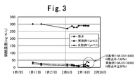
- FIG. 3 shows changes with time in the nitric acid concentration of raw water and the nitric acid concentration of treated water in this treatment.
- stable denitrification treatment could be performed at a nitrogen removal rate of 90% or more during the operation period.
- the granule particle size in the USB reaction tower 1 was about 2 mm, and the inside of the reaction tower 1 maintained good fluidity.
- the MLSS in the reaction tower 1 was 38,000 mg / L, and the granules were kept at a high concentration in the reaction tower 1.
- the HRT in the first denitrification step was 0.81 hours
- the HRT of the second denitrification process was estimated to be 1.89 hours.
- Example 1 In Example 1, it processed similarly except having added sodium hydroxide aqueous solution so that pH in the circulation tank 3 might be set to 7.2. The change with time in the nitric acid concentration of the treated water at this time is as shown in FIG. 3, and the treatment efficiency decreased with time and the nitrogen removal rate was lower than 90%.
- the granule particle size in the reaction tower 1 is 3 mm or more, the association and outflow of the granules increase, and the MLSS in the reaction tower 1 is about 18,000 mg / L after about one month from the start of operation. Two months after the start, all the granules in the reaction tower 1 had flowed out.
- Example 2 Raw water having a nitric acid concentration of 290 mg-N / L was treated with the floating denitrification apparatus shown in FIG. Both the capacity
- the raw water was adjusted to have a pH in the first denitrification tank 12 of 6.5 and a pH in the second denitrification tank 13 of 7.2 by adding a sodium hydroxide aqueous solution in the pH adjustment tank 11.
- methanol was added at 870 mg / L, and the system was operated at a volumetric load of 1.2 kg-N / m 3 / day and HRT of 6.8 hours. When operated for one month or longer under these conditions, the nitrogen removal rate of the treated water was stably maintained at 90% or higher. Further, the generated denitrification sludge was excellent in sedimentation property and maintained good solid-liquid separation properties in the sedimentation tank 14.
- Example 2 In Example 2, the treatment was performed under the same conditions except that the pH of the first denitrification tank 12 was adjusted to 7.2. When operated for one month or longer under these conditions, the nitrogen removal rate of the treated water was less than 90%. Moreover, the sedimentation property of sludge was bad, the interface rise in the sedimentation tank 14, and the sludge density
Landscapes
- Life Sciences & Earth Sciences (AREA)
- Microbiology (AREA)
- Biodiversity & Conservation Biology (AREA)
- Hydrology & Water Resources (AREA)
- Engineering & Computer Science (AREA)
- Environmental & Geological Engineering (AREA)
- Water Supply & Treatment (AREA)
- Chemical & Material Sciences (AREA)
- Organic Chemistry (AREA)
- Purification Treatments By Anaerobic Or Anaerobic And Aerobic Bacteria Or Animals (AREA)
- Treatment Of Sludge (AREA)
Abstract
Description
この方法は、付着担体を用いることなく脱窒細菌を選択的に自己造粒させて、反応塔内に脱窒細菌を高濃度の粒状に凝集させたグラニュールの汚泥床を形成し、NOx含有排水を反応塔下部から導入して水素供与体の存在下でこのグラニュールと接触させて排水中の(亜)硝酸イオンを分解し、脱窒処理水を反応塔上部の固気液分離部から取り出すものである。
この現象は、原水に含まれる栄養塩、ミネラル、重金属等が少ない場合も発生する。例えば、電子部品の製造分野で排出されるフッ硝酸排水のように、超純水に硝酸や一部の無機物のみを含むだけの排水を原水とする場合には、担体やグラニュールへの菌体の過剰付着や粘質物の過剰生成により、処理効率が低下する。
即ち、例えば、自己造粒法による脱窒処理の場合、原水は水素供与体と共にUSB反応塔に導入され、浮遊細菌やグラニュールにより、窒素ガスまで還元される。この時、低濃度原水の高負荷運転でHRTが低く、例えば、10時間以下となると、反応塔から浮遊菌が洗い流される割合が多くなり、脱窒反応の大部分が、グラニュールを構成する脱窒細菌に依存することとなる。このような場合、脱窒細菌は系内へ残ろうとするため、グラニュールへの菌体の過剰付着や粘質物の過剰生成を行い、結果として、反応塔内の流動性は著しく低下する。
ただし、脱窒工程全体にわたって弱酸性とすると、脱窒細菌の活性は大幅に低下することとなるため、本発明では、pH4以上7未満の第1脱窒工程後に、pH7~8の第2脱窒工程を行う。
このpH上昇で反応塔1から流出する処理水のpHが7~8の範囲であれば、この反応塔1内では、第1脱窒工程を行っている領域の上側の領域においてpH7~8の第2脱窒工程が行われているため、反応塔1に更にアルカリを添加する必要はない。ただし、反応塔1の流出水のpHが7未満の場合には、反応塔1の中間部の1ヶ所又は複数個所でアルカリを添加して、反応塔1の流出水のpHが7~8の範囲となるように調整する。アルカリ添加部の高さは、反応塔1の底部から、グラニュール汚泥床1Aの流動状態における高さの1/20~1/2程度の高さが好ましい。
この添加量は、通常、脱窒処理に供される水中のメタノール等の水素供与体の濃度がNOx-Nに対して1.8~3.5g-メタノール/g-NOx-N程度となる量である。また、脱窒処理には、脱窒細菌の栄養塩やミネラル、重金属等が必要となることから、原水中にこれらの成分が不足する場合には、適宜これらを補給する。
図1に示すUSB脱窒装置(反応塔容量3.0L,高さ100cm)を用いて、硝酸を含有する原水に、水素供与体としてのメタノールを620mg/Lと重金属混合液(Fe、Cu、Ni、Mo、Co)10mg/Lとリン酸5mg/Lを添加して処理した(以下、これらを添加したものを「調整原水」と称す。)。
図3に示されるように、運転期間中、窒素除去率90%以上で安定な脱窒処理を行えた。
また、USB反応塔内1のグラニュール粒径は2mm程度であり、反応塔1内は良好な流動性を維持していた。運転開始から約一ヶ月後における反応塔1内のMLSSは38,000mg/Lで、反応塔1内にグラニュールが高濃度に保持されていた。
実施例1において、循環槽3内のpHが7.2となるように水酸化ナトリウム水溶液を添加したこと以外は同様にして処理を行った。
このときの処理水の硝酸濃度の経時変化は、図3に示す通りであり、経時により処理効率は低下し、窒素除去率は90%より低くなった。
また、反応塔1内のグラニュール粒径は3mm以上となり、グラニュール同士の会合、流出が多くなり、運転開始から約一ヶ月後における反応塔1内のMLSSは18,000mg/Lで、運転開始二ヵ月後には、反応塔1内のグラニュールはすべて流出した。
図2に示す浮遊式脱窒装置で硝酸濃度290mg-N/Lの原水の処理を行った。第1脱窒槽12及び第2脱窒槽13の容量はいずれも1.5Lである。
原水はpH調整槽11において水酸化ナトリウム水溶液を添加することにより、第1脱窒槽12内のpHが6.5、第2脱窒槽13内のpHが7.2となるようにpH調整した。
水素供与体としてはメタノールを870mg/L添加し、容積負荷1.2kg-N/m3/day、HRT6.8時間で運転した。
この条件で一ヶ月以上運転したところ、処理水の窒素除去率は90%以上を安定して維持していた。
また、生成した脱窒汚泥は沈降性に優れ、沈殿槽14で良好な固液分離性を維持していた。
実施例2において、第1脱窒槽12のpHが7.2となるようにpH調整したこと以外は同様の条件で処理を行った。
この条件で一ヶ月以上運転したところ、処理水の窒素除去率は90%未満となった。
また、汚泥の沈降性が悪く、沈殿槽14での界面上昇、汚泥濃度の低下が発生し、運転開始二ヶ月後には、窒素除去率は70%以下に低下した。
なお、本出願は、2009年4月22日付で出願された日本特許出願(特願2009-104278)に基づいており、その全体が引用により援用される。
Claims (6)
- 硝酸イオン及び/又は亜硝酸イオンを含む原水を、水素供与体の存在下に脱窒細菌と接触させて脱窒処理する脱窒工程を含む脱窒方法において、
該脱窒工程は、pH4以上7未満で脱窒処理する第1脱窒工程と、その後、pH7~8で脱窒処理する第2脱窒工程とを含むことを特徴とする脱窒方法。 - 請求項1において、前記脱窒工程は、脱窒細菌の造粒物が充填された反応塔に、原水を上向流で通水して行う工程であり、該反応塔の下部で前記第1脱窒工程を行い、それよりも上部で前記第2脱窒工程を行うことを特徴とする脱窒方法。
- 請求項2において、原水を該反応塔に導入するに先立ち、pH4以上7未満に調整することを特徴とする脱窒方法。
- 請求項2において、該反応塔からの流出水のpHが7~8になるように、該反応塔の中間部において、アルカリを添加することを特徴とする脱窒方法。
- 請求項2において、前記反応塔のHRTが10時間以下となる条件で処理することを特徴とする脱窒方法。
- 請求項1ないし5のいずれか1項において、前記原水の硝酸イオン及び亜硝酸イオンの合計の濃度が1,000mg-N/L以下であることを特徴とする脱窒方法。
Priority Applications (1)
| Application Number | Priority Date | Filing Date | Title |
|---|---|---|---|
| CN201080013608.8A CN102361827B (zh) | 2009-04-22 | 2010-04-06 | 脱氮方法 |
Applications Claiming Priority (2)
| Application Number | Priority Date | Filing Date | Title |
|---|---|---|---|
| JP2009-104278 | 2009-04-22 | ||
| JP2009104278A JP2010253352A (ja) | 2009-04-22 | 2009-04-22 | 脱窒方法 |
Publications (1)
| Publication Number | Publication Date |
|---|---|
| WO2010122898A1 true WO2010122898A1 (ja) | 2010-10-28 |
Family
ID=43011019
Family Applications (1)
| Application Number | Title | Priority Date | Filing Date |
|---|---|---|---|
| PCT/JP2010/056207 Ceased WO2010122898A1 (ja) | 2009-04-22 | 2010-04-06 | 脱窒方法 |
Country Status (5)
| Country | Link |
|---|---|
| JP (1) | JP2010253352A (ja) |
| KR (1) | KR20120022726A (ja) |
| CN (1) | CN102361827B (ja) |
| TW (1) | TWI513667B (ja) |
| WO (1) | WO2010122898A1 (ja) |
Families Citing this family (4)
| Publication number | Priority date | Publication date | Assignee | Title |
|---|---|---|---|---|
| JP5421862B2 (ja) * | 2010-06-18 | 2014-02-19 | オルガノ株式会社 | 過塩素酸イオン含有水の処理方法および過塩素酸イオン含有水の処理装置 |
| JP5636236B2 (ja) * | 2010-09-21 | 2014-12-03 | Dowaテクノロジー株式会社 | 硝酸含有水の処理方法及び硝酸含有水の処理装置 |
| JP5799633B2 (ja) * | 2011-07-22 | 2015-10-28 | 栗田工業株式会社 | アミン含有排水の生物処理法及び処理装置 |
| JP6461408B1 (ja) * | 2018-06-22 | 2019-01-30 | オルガノ株式会社 | 水処理方法および水処理装置 |
Citations (4)
| Publication number | Priority date | Publication date | Assignee | Title |
|---|---|---|---|---|
| JP2002177986A (ja) * | 2000-12-08 | 2002-06-25 | Kurita Water Ind Ltd | 生物学的脱窒装置 |
| JP2003053383A (ja) * | 2001-08-17 | 2003-02-25 | Nippon Steel Corp | 廃水からの窒素の除去方法 |
| JP2003290790A (ja) * | 2002-04-03 | 2003-10-14 | Kurita Water Ind Ltd | 脱窒装置の立ち上げ方法 |
| JP2004298763A (ja) * | 2003-03-31 | 2004-10-28 | Nippon Steel Chem Co Ltd | 硝酸性窒素の除去方法及び除去装置 |
Family Cites Families (6)
| Publication number | Priority date | Publication date | Assignee | Title |
|---|---|---|---|---|
| JP3256755B2 (ja) * | 1995-03-30 | 2002-02-12 | 日立造船株式会社 | 脱窒反応における供給廃水量の制御方法 |
| JP4321798B2 (ja) * | 2001-08-31 | 2009-08-26 | 新東工業株式会社 | 脱窒反応槽の水素供与体量制御方法とその装置 |
| TWI449674B (zh) * | 2004-12-14 | 2014-08-21 | Kurita Water Ind Ltd | Drainage treatment device and treatment method |
| JP4775944B2 (ja) * | 2005-08-24 | 2011-09-21 | オルガノ株式会社 | 排水の処理方法および装置 |
| CN101306903B (zh) * | 2007-05-18 | 2011-09-21 | 中国石油化工股份有限公司 | 一种高氨氮浓度废水生化处理方法 |
| CN101293707B (zh) * | 2008-06-20 | 2011-08-10 | 北京城市排水集团有限责任公司 | 消化污泥脱水液生物膜全程自养脱氮的装置和方法 |
-
2009
- 2009-04-22 JP JP2009104278A patent/JP2010253352A/ja active Pending
-
2010
- 2010-04-06 WO PCT/JP2010/056207 patent/WO2010122898A1/ja not_active Ceased
- 2010-04-06 KR KR20117021950A patent/KR20120022726A/ko not_active Withdrawn
- 2010-04-06 CN CN201080013608.8A patent/CN102361827B/zh not_active Expired - Fee Related
- 2010-04-15 TW TW099111818A patent/TWI513667B/zh not_active IP Right Cessation
Patent Citations (4)
| Publication number | Priority date | Publication date | Assignee | Title |
|---|---|---|---|---|
| JP2002177986A (ja) * | 2000-12-08 | 2002-06-25 | Kurita Water Ind Ltd | 生物学的脱窒装置 |
| JP2003053383A (ja) * | 2001-08-17 | 2003-02-25 | Nippon Steel Corp | 廃水からの窒素の除去方法 |
| JP2003290790A (ja) * | 2002-04-03 | 2003-10-14 | Kurita Water Ind Ltd | 脱窒装置の立ち上げ方法 |
| JP2004298763A (ja) * | 2003-03-31 | 2004-10-28 | Nippon Steel Chem Co Ltd | 硝酸性窒素の除去方法及び除去装置 |
Also Published As
| Publication number | Publication date |
|---|---|
| KR20120022726A (ko) | 2012-03-12 |
| TWI513667B (zh) | 2015-12-21 |
| TW201107251A (en) | 2011-03-01 |
| CN102361827B (zh) | 2014-07-02 |
| CN102361827A (zh) | 2012-02-22 |
| JP2010253352A (ja) | 2010-11-11 |
Similar Documents
| Publication | Publication Date | Title |
|---|---|---|
| US20140367330A1 (en) | Wastewater treatment process that utilizes granular sludge to reduce cod concentration in wastewater | |
| US7407580B2 (en) | System and method for treating carbon, nitrogen, phosphorous containing wastewater | |
| JP4649911B2 (ja) | 有機物及び窒素含有排水の処理方法 | |
| JP4872171B2 (ja) | 生物脱窒装置 | |
| JP5791359B2 (ja) | 廃水処理方法 | |
| JP2017000987A (ja) | 生物学的窒素除去方法及び窒素含有廃水の処理装置 | |
| WO2010122898A1 (ja) | 脱窒方法 | |
| JP2003033790A (ja) | 脱窒装置及び脱窒方法 | |
| CN110255812B (zh) | 一种在畜禽养殖污水处理过程中保留氨氮去除抗生素的生化与高级氧化组合方法 | |
| Ji et al. | Optimization of up-flow velocity enhances the performance of partial denitrification/anammox process in expanded granular sludge bed reactor based on the formation of hydroxyapatite | |
| CN101693581B (zh) | 水解-催化铁-好氧耦合处理有毒有害难降解废水方法 | |
| CN111470622A (zh) | 一种高浓度硫酸盐废水中的硝酸盐氮的处理方法及装置 | |
| JP3811522B2 (ja) | 火力発電所排水の処理方法 | |
| JP5930805B2 (ja) | 有機性廃水の嫌気性廃水処理方法及び装置 | |
| WO2019244969A1 (ja) | 水処理方法および水処理装置 | |
| CN102485670B (zh) | 一种柠檬酸生产废水的处理方法 | |
| JP5746853B2 (ja) | 排水処理装置および排水処理方法 | |
| CN108033600A (zh) | 一种高浓高毒农药废水的集成预处理方法及应用 | |
| JP5077334B2 (ja) | 窒素除去処理装置及び窒素除去処理方法 | |
| CN101973661A (zh) | 处理五倍子加工废水的方法 | |
| JP6880894B2 (ja) | Anammoxプロセスを有する排水処理方法 | |
| JP2014133210A (ja) | 有機性廃水の嫌気処理方法及び嫌気性処理装置 | |
| CN112851025B (zh) | 针对高氨氮、高硝态氮废水的高效深度一体化处理系统 | |
| JP2007117948A (ja) | 高濃度有機性廃液の処理方法及び装置 | |
| JPH09187790A (ja) | セレン含有水の処理方法 |
Legal Events
| Date | Code | Title | Description |
|---|---|---|---|
| WWE | Wipo information: entry into national phase |
Ref document number: 201080013608.8 Country of ref document: CN |
|
| 121 | Ep: the epo has been informed by wipo that ep was designated in this application |
Ref document number: 10766956 Country of ref document: EP Kind code of ref document: A1 |
|
| ENP | Entry into the national phase |
Ref document number: 20117021950 Country of ref document: KR Kind code of ref document: A |
|
| WWE | Wipo information: entry into national phase |
Ref document number: 7021/CHENP/2011 Country of ref document: IN |
|
| NENP | Non-entry into the national phase |
Ref country code: DE |
|
| 122 | Ep: pct application non-entry in european phase |
Ref document number: 10766956 Country of ref document: EP Kind code of ref document: A1 |