WO2010106877A1 - リチウムイオン二次電池及びその製造方法 - Google Patents
リチウムイオン二次電池及びその製造方法 Download PDFInfo
- Publication number
- WO2010106877A1 WO2010106877A1 PCT/JP2010/052674 JP2010052674W WO2010106877A1 WO 2010106877 A1 WO2010106877 A1 WO 2010106877A1 JP 2010052674 W JP2010052674 W JP 2010052674W WO 2010106877 A1 WO2010106877 A1 WO 2010106877A1
- Authority
- WO
- WIPO (PCT)
- Prior art keywords
- positive electrode
- lithium
- vinyl ether
- secondary battery
- mol
- Prior art date
- Legal status (The legal status is an assumption and is not a legal conclusion. Google has not performed a legal analysis and makes no representation as to the accuracy of the status listed.)
- Ceased
Links
Classifications
-
- H—ELECTRICITY
- H01—ELECTRIC ELEMENTS
- H01M—PROCESSES OR MEANS, e.g. BATTERIES, FOR THE DIRECT CONVERSION OF CHEMICAL ENERGY INTO ELECTRICAL ENERGY
- H01M4/00—Electrodes
- H01M4/02—Electrodes composed of, or comprising, active material
- H01M4/36—Selection of substances as active materials, active masses, active liquids
- H01M4/58—Selection of substances as active materials, active masses, active liquids of inorganic compounds other than oxides or hydroxides, e.g. sulfides, selenides, tellurides, halogenides or LiCoFy; of polyanionic structures, e.g. phosphates, silicates or borates
- H01M4/5825—Oxygenated metallic salts or polyanionic structures, e.g. borates, phosphates, silicates, olivines
-
- H—ELECTRICITY
- H01—ELECTRIC ELEMENTS
- H01M—PROCESSES OR MEANS, e.g. BATTERIES, FOR THE DIRECT CONVERSION OF CHEMICAL ENERGY INTO ELECTRICAL ENERGY
- H01M10/00—Secondary cells; Manufacture thereof
- H01M10/05—Accumulators with non-aqueous electrolyte
- H01M10/052—Li-accumulators
- H01M10/0525—Rocking-chair batteries, i.e. batteries with lithium insertion or intercalation in both electrodes; Lithium-ion batteries
-
- H—ELECTRICITY
- H01—ELECTRIC ELEMENTS
- H01M—PROCESSES OR MEANS, e.g. BATTERIES, FOR THE DIRECT CONVERSION OF CHEMICAL ENERGY INTO ELECTRICAL ENERGY
- H01M4/00—Electrodes
- H01M4/02—Electrodes composed of, or comprising, active material
- H01M4/62—Selection of inactive substances as ingredients for active masses, e.g. binders, fillers
- H01M4/621—Binders
- H01M4/622—Binders being polymers
-
- Y—GENERAL TAGGING OF NEW TECHNOLOGICAL DEVELOPMENTS; GENERAL TAGGING OF CROSS-SECTIONAL TECHNOLOGIES SPANNING OVER SEVERAL SECTIONS OF THE IPC; TECHNICAL SUBJECTS COVERED BY FORMER USPC CROSS-REFERENCE ART COLLECTIONS [XRACs] AND DIGESTS
- Y02—TECHNOLOGIES OR APPLICATIONS FOR MITIGATION OR ADAPTATION AGAINST CLIMATE CHANGE
- Y02E—REDUCTION OF GREENHOUSE GAS [GHG] EMISSIONS, RELATED TO ENERGY GENERATION, TRANSMISSION OR DISTRIBUTION
- Y02E60/00—Enabling technologies; Technologies with a potential or indirect contribution to GHG emissions mitigation
- Y02E60/10—Energy storage using batteries
Definitions
- the present invention relates to a lithium ion secondary battery and a method for manufacturing the same. More specifically, the present invention relates to a lithium ion secondary battery in which a positive electrode mixture layer containing lithium iron phosphate and a conductive material is laminated on a positive electrode assembly using hydrocarbon vinyl ether-modified polyvinyl alcohol as a resin binder.
- a positive electrode active material of a lithium ion secondary battery a composite oxide, a chalcogen compound of lithium and a transition metal such as cobalt, nickel, manganese, or a compound having these composite compounds and various additive elements has been used. It has been.
- the carbon film-covered olivine structure has a phosphoric acid skeleton structure with extremely low oxygen release, high thermal stability, and enhanced conductivity to facilitate rapid occlusion / release of lithium ions. Lithium iron phosphate has been used.
- the positive electrode of the lithium ion secondary battery is prepared by dispersing these positive electrode active material and conductive material in a solvent in which a resin binder is dissolved, and coating and drying on a metal foil that is a positive electrode current collector. It is manufactured by doing.
- lithium iron phosphate hereinafter abbreviated as “LiFePO 4 ”
- LiFePO 4 lithium iron phosphate
- fluororesin or polyvinyl alcohol (hereinafter abbreviated as “PVA”) is used, and in particular, polyvinylidene fluoride (hereinafter abbreviated as “PVDF”) or thermosetting plasticization which is a fluororesin.
- PVA polyvinylidene fluoride
- thermosetting plasticized PVA is a compound obtained by reacting unmodified PVA having a high degree of saponification with alkenyl succinic anhydride in an organic solvent in a substantially anhydrous state (for example, see Patent Document 1).
- NMP N-methyl-2-pyrrolidone
- Nitrogen-containing organic solvents such as ureas
- NMP nitrogen-containing organic solvents
- NMP must be recovered because the solvent vapor generated during drying becomes an environmental problem if released to the atmosphere as it is.
- NMP has a very high boiling point of 204 ° C., and requires a lot of energy during drying.
- electrolytic solution resistance the resistance to the electrolytic solution
- the non-aqueous solvent that is the electrolytic solution absorbs and swells and the electrolytic solution is depleted. Adhesive deterioration as a binder resin is caused, which becomes a factor of reducing the energy capacity in the charge / discharge cycle of the lithium secondary battery.
- LiFePO 4 when laminating LiFePO 4 as a mixture layer, water that has a low boiling point and does not cause environmental problems can be used as a solvent, lithium iron phosphate can be uniformly dispersed, and the electrolytic solution resistance is also improved. An excellent resin binder is desired.
- the main object is to provide a lithium ion secondary battery in which a positive electrode mixture layer containing LiFePO 4 and a conductive material is laminated.
- the present invention provides a positive electrode in which a positive electrode mixture layer made of a mixture containing LiFePO 4 , a conductive material, and a hydrocarbon vinyl ether-modified polyvinyl alcohol as a resin binder is laminated on a positive electrode current collector,
- a lithium ion secondary battery having a negative electrode, a separator, and a nonaqueous solvent containing a lithium salt supporting electrolyte.
- the hydrocarbon vinyl ether-modified polyvinyl alcohol is a copolymer of a vinyl ether having a hydrocarbon group having 5 to 30 carbon atoms in the molecule and a monomer having a vinyl ester unit.
- the amount is 0.01 to 10 mol%, the degree of polymerization is 300 to 5000, and the degree of saponification is 93 to 99.99 mol% with respect to 100 mol% of ester units.
- the amount of the resin binder is desirably 2 to 10 parts by mass with respect to 100 parts by mass of LiFePO 4 .
- the negative electrode active material is desirably a lithium metal, a lithium alloy, or a carbonaceous material that can occlude and release lithium ions.
- the present invention also provides a positive electrode mixture in which a dispersion solution in which LiFePO 4 , a conductive material, and a hydrocarbon vinyl ether-modified polyvinyl alcohol as a resin binder are dissolved and dispersed in water is applied onto a positive electrode current collector and dried.
- a method for producing a lithium ion secondary battery including a step of laminating layers is also provided.
- a vinyl ether having a hydrocarbon group having 5 to 30 carbon atoms in the molecule and a monomer having a vinyl ester unit are copolymerized, and the modification amount is 0.01% with respect to 100 mol% of the ester unit.
- the method includes a step of obtaining vinyl ether-modified polyvinyl alcohol.
- water that has a low boiling point and does not cause environmental problems can be used as a solvent, LiFePO 4 can be uniformly dispersed, and a resin binder having excellent electrolytic solution resistance can be used on the positive electrode assembly.
- a lithium ion secondary battery in which a positive electrode mixture layer containing LiFePO4 and a conductive material is laminated is provided.
- a lithium ion secondary battery according to the present invention comprises a positive electrode mixture layer comprising a mixture containing LiFePO 4 , a conductive material and a hydrocarbon vinyl ether-modified PVA as a resin binder. It has a positive electrode laminated thereon, a negative electrode using a negative electrode active material, a separator, and a nonaqueous solvent containing a lithium salt supporting electrolyte.
- LiFePO 4 As the positive electrode active material, lithium iron phosphate (LiFePO 4 ) having an olivine structure coated with a carbon film is used. Although LiFePO 4 has a potential of 3.4 V and a theoretical capacity as small as about 170 mAh / g, since PO 4 forms a stable skeletal structure, it has excellent thermal stability during charge and discharge.
- the primary particle diameter of LiFePO 4 is preferably 0.1 to 500 nm, more preferably 10 to 300 nm, and most preferably 50 to 100 nm. If the particle diameter is small, the surface area becomes large, resulting in poor dispersion. On the other hand, if the particle size is large, the specific surface area becomes small, so that the reaction area of lithium becomes small or the lithium diffusion path in the particle becomes large, so that high output cannot be obtained.
- (C) Current collector Generally, aluminum is preferably used for the positive electrode current collector.
- the shape of the current collector is not particularly limited, but a foil shape, a net shape, an expanded metal, or the like can be used.
- the shape of the current collector is preferably that having a large void area, such as a net or expanded metal, from the viewpoint of facilitating holding of the electrolytic solution after bonding, and preferably having a thickness of about 0.001 to 0.03 mm.
- (D) Resin Binder Hydrocarbon vinyl ether-modified PVA is used as a resin binder for laminating LiFePO 4 and a conductive material as a positive electrode mixture layer on a current collector.
- the hydrocarbon group vinyl ether-modified PVA used in the present invention is a hydrocarbon group having 5 to 30 carbon atoms in the molecule, specifically, an alkyl group, an allyl group, a cycloalkyl group, an alkenyl group, an aryl group, an aralkyl group or a silyl group. These are obtained by copolymerizing a vinyl monomer having any one or more groups and a monomer having a vinyl ester unit, followed by saponification, washing and drying.
- alkyl group examples include amyl vinyl ether, hexyl vinyl ether, heptyl vinyl ether, octyl vinyl ether, nonyl vinyl ether, decyl vinyl ether, dodecyl vinyl ether, tridecyl vinyl ether, tetradecyl vinyl ether, pentadecyl vinyl ether, hexadecyl vinyl ether, octadecyl vinyl ether, etc.
- alkenyl groups oleyl vinyl ether, linolyl vinyl ether, etc.
- phenyl vinyl ether, 1-naphthyl vinyl ether, 2-naphthyl vinyl ether, 2-methylphenyl vinyl ether, 3-methylphenyl vinyl ether, 4- Methyl phenyl vinyl ether, 3 Etc. meth hydroxyphenyl vinyl ether, and the aralkyl groups include benzyl vinyl.
- the copolymerization amount (modification amount) of the hydrocarbon group vinyl ether is 0.01 to 10 mol%, preferably 0.1 to 5 mol%, more preferably 0.5 to 3 mol% with respect to 100 mol% of the ester unit. It is. When the amount of modification is small, the dispersibility of LiFePO 4 and conductive material deteriorates. On the other hand, when the amount of modification is large, the viscosity of the dispersion becomes high, which causes a problem during coating.
- the hydrolysis rate (degree of saponification) of the hydrocarbon group vinyl ether-modified PVA is 93 to 99.99 mol%, preferably 95 to 99.99 mol%, more preferably 97 to 99.99 mol%.
- degree of saponification is low, the electrolyte solution resistance of the positive electrode mixture layer laminated on the current collector is lowered. Further, when the degree of saponification is high, industrial production becomes difficult.
- the degree of polymerization of the hydrocarbon group vinyl ether-modified PVA is 300 to 5000, preferably 1000 to 3500, and more preferably 1500 to 2500.
- the degree of polymerization is low, the dispersibility of LiFePO 4 and conductive material deteriorates.
- the degree of polymerization is high, the viscosity of the dispersion solution becomes high, which causes a problem during coating.
- the polymerization degree means the viscosity average polymerization degree.
- the degree of polymerization is saponified until the saponification degree is 99.5 mol% or more, and then re-acetylated with acetic anhydride and pyridine.
- the vinyl acetate was determined from the intrinsic viscosity [ ⁇ ] (g / dl) using a method for measuring the average degree of polymerization specified in JISK-6725.
- the hydrocarbon group vinyl ether-modified PVA may be copolymerized with a monomer copolymerizable with a hydrocarbon group vinyl ether and a monomer having a vinyl ester unit.
- the copolymerizable monomer include olefins such as ethylene, propylene, 1-butene and isobutene, unsaturated acids such as acrylic acid, methacrylic acid, crotonic acid, phthalic acid, maleic acid and itaconic acid, or salts thereof.
- monoalkyl esters or dialkyl esters having 1 to 18 carbon atoms acrylamide, N-alkyl acrylamides having 1 to 18 carbon atoms, N, N-dialkyl acrylamide, diacetone acrylamide, 2-acrylamidopropanesulfonic acid and salts thereof
- Acrylamides such as acrylamidopropyldimethylamine and salts thereof or quaternary salts thereof, methacrylamide, N-alkyl methacrylamide having 1 to 18 carbon atoms, N, N-dialkyl methacrylamide, diacetone methacrylamide, Methacrylamide such as chloramidopropane sulfonic acid and its salt, methacrylamide propyldimethylamine and its salt or its quaternary salt, alkyl vinyl ether having 1 to 4 carbon atoms, hydroxyalkyl vinyl ether, alkoxyalkyl vinyl ether, etc.
- the polymerization initiator used in the solution polymerization is not particularly limited, but azobisisobutyronitrile, azobis-2,4-dimethylpareronitrile, azobis (4-methoxy-2,4-dimethylpareronitrile) ) And other azo compounds, acetyl peroxide, benzoyl peroxide, lauroyl peroxide, acetylcyclohexylsulfonyl peroxide, peroxides such as 2,4,4-trimethylpentyl-2-peroxyphenoxyacetate, and diisopropylpropyloxy Percarbonate compounds such as dicarbonate, di-2-ethylhexyl peroxydicarbonate, diethoxyethyl peroxydicarbonate, t-butylperoxyneodecanate, ⁇ -cumylperoxyneodecane, t-butylperoxyneo Decane Perester compounds such as azo-bis di
- the saponification of the copolymer can be carried out by dissolving the copolymer in alcohol and hydrolyzing the ester in the molecule in the presence of an alkali catalyst or an acid catalyst.
- the alcohol include methanol, ethanol, and propanol.
- concentration of the copolymer in the alcohol is not particularly limited, but is selected from the range of 10 to 80% by weight.
- an alkali catalyst such as an alkali metal hydroxide or alcoholate such as sodium hydroxide, potassium hydroxide, sodium methylate, sodium ethylate, potassium methylate, etc. can be used.
- an inorganic acid aqueous solution such as hydrochloric acid or sulfuric acid, or an organic acid such as p-toluenesulfonic acid can be used.
- the amount of these catalysts used is preferably 1 to 100 mmol equivalents relative to the copolymer.
- the saponification temperature is not particularly limited, but is in the range of 10 to 70 ° C, preferably 30 to 40 ° C.
- the reaction time is not particularly limited, but is carried out for 30 minutes to 3 hours.
- the positive electrode comprises a dispersion solution (hereinafter referred to as slurry) obtained by dissolving and dispersing LiFePO 4 , a conductive material, and the above-mentioned hydrocarbon vinyl ether-modified PVA as a resin binder in water. It is obtained by coating and drying on a current collector and laminating a positive electrode mixture layer.
- slurry dispersion solution obtained by dissolving and dispersing LiFePO 4 , a conductive material, and the above-mentioned hydrocarbon vinyl ether-modified PVA as a resin binder in water. It is obtained by coating and drying on a current collector and laminating a positive electrode mixture layer.
- the amount of the resin binder in the slurry is preferably 2 to 10 parts by mass with respect to 100 parts by mass of LiFePO 4 .
- the amount of the binder is small, there are problems that LiFePO 4 is not uniformly dispersed in the coating liquid and the strength of the dried film after coating is not obtained.
- the amount of active materials in a positive electrode will reduce, and charge capacity will reduce.
- the slurry can be applied by a general method. Examples thereof include a reverse roll method, a direct roll method, a blade method, a knife method, an extrusion method, a curtain method, a gravure method, a bar method, a dip method, and a squeeze method. Of these, blade method (comma roll or die cut), knife method and extrusion method are preferable. Under the present circumstances, the surface state of a favorable coating layer can be obtained by selecting the said coating method according to the solution physical property and drying property of a binder.
- the application may be performed on one side or both sides, and in the case of both sides, each side may be sequentially or simultaneously.
- the application may be continuous, intermittent, or striped.
- the application thickness, length, and width of the slurry may be appropriately determined according to the size of the battery.
- the electrode can be pressed as needed.
- a generally adopted method can be used, and a die pressing method and a calendar pressing method (cold or hot roll) are particularly preferable.
- the pressing pressure is not particularly limited, but is preferably 0.2 to 3 t / cm 2 .
- Negative electrode active material examples include lithium metal, alloys of Li and low melting point metals such as Pb, Bi, and Sn, lithium alloys such as Li-Al alloys, and carbonaceous materials. Is used.
- the carbonaceous negative electrode active material any material that can occlude and release lithium ions, which are the main components of battery operation, can be used.
- Carbon-based compounds such as graphitizable carbon, non-graphitizable carbon, polyacene, polyacetylene, pyrene, An aromatic hydrocarbon compound containing an acene structure such as perylene is preferably used.
- These active materials are used in a particulate form, and those having a particle size of 1 to 30 ⁇ m can be used, and preferably 3 to 15 ⁇ m.
- (C) Current collector Normally, copper is preferably used for the negative electrode current collector.
- the shape of the current collector is not particularly limited, but a foil shape, a net shape, an expanded metal, or the like can be used.
- the shape of the current collector is preferably that having a large void area, such as a net or expanded metal, from the viewpoint of facilitating holding of the electrolytic solution after bonding, and preferably having a thickness of about 0.001 to 0.03 mm.
- any resin binder that does not dissolve in the electrolyte and does not cause an electrochemical reaction inside the electrode laminate can be used.
- Teflon registered trademark
- polyethylene nitrile rubber, polybutadiene, butyl rubber, polystyrene, styrene / butadiene rubber, nitrocellulose, cyanoethyl cellulose, polyacrylonitrile, polyvinyl fluoride, polyvinyl acetate, polyethylene, polystyrene, polypropylene, poly Homopolymers or copolymers of tetrafluoroethylene, polymethyl methacrylate, polychloroprene, polyvinyl pyridine, ethylene propylenediamine rubber, vinylidene fluoride, ethylene fluoride, acrylonitrile, ethylene oxide, and the like can be used.
- (E) Manufacturing method of negative electrode The manufacturing method of the negative electrode is the same as that of the positive electrode. However, when the negative electrode is a carbonaceous negative electrode, it is prepared from a carbon body and a binder using a wet papermaking method, or It is prepared by applying and drying on a current collector from a paint mixed with a binder.
- any separator can be used as long as it has sufficient strength, such as an electronic insulating porous film, a net, and a nonwoven fabric.
- a material that has low resistance to ion migration of the electrolyte solution and excellent in solution holding is not particularly limited, and examples thereof include glass fiber, polyethylene, polypropylene, polyester, Teflon (registered trademark), polyflon, or a layered composite thereof. From the viewpoint of adhesion and safety, polyethylene, polypropylene, or a layered composite film thereof is desirable.
- an electrolyte in the electrolytic solution electrolyte can use any known lithium salt, LiClO 4, LiBF 4, LiBF 6, LiPF 6, LiCF 3 SO 3, LiCF 3 CO 2, LiAsF 6, LiSbF 6, LiB 10 Cl 10 , LiAlCl 4 , LiCl, LiBr, LiI, LiB (C 2 H 5 ) 4 , LiCF 3 SO 3 , LiCH 3 SO 3 , LiCF 3 SO 3 , LiC 4 F 9 SO 3 , LiN (CF 3 SO 2 ) 2 , LiN (C 2 F 5 SO 2 ) 2 , LiC (CF 3 SO 2 ) 3 , lithium lower fatty acid carboxylate and the like may be mentioned, but not particularly limited.
- the medium for dissolving the electrolyte is not particularly limited as long as it functions as a secondary battery.
- carbonates such as propylene carbonate, ethylene carbonate, butylene carbonate, dimethyl carbonate, diethyl carbonate, and methyl ethyl carbonate.
- Lactones such as ⁇ -butyrolactone; ethers such as trimethoxymethane, 1,2-dimethoxyethane, diethyl ether, 2-ethoxyethane, tetrahydrofuran, 2-methyltetrahydrofuran; sulfoxides such as dimethyl sulfoxide; -Oxolanes such as dioxolane and 4-methyl-1,3-dioxolane; nitrogen-containing compounds such as acetonitrile, nitromethane and N-methyl-2-pyrrolidone; methyl formate, methyl acetate, ethyl acetate, butyrate , Esters such as methyl propionate, ethyl propionate, phosphoric acid triester; inorganic acid esters such as dimethyl carbonate, diethyl carbonate, carbonate diester such as dipropyl carbonate; amides such as dimethylformamide, dimethylacetamide; diglyme, Glymes such as
- non-aqueous electrolytes are preferably non-aqueous electrolytes in which LiPF 6 is dissolved in carbonates, and the electrolyte concentration varies depending on the electrode and electrolyte used, but is preferably 0.5 to 3 mol / l.
- a solution obtained by dissolving a resin binder in pure water so as to be 12% is uniformly cast on a polyethylene terephthalate (hereinafter abbreviated as “PET”) film so that the film thickness after drying and heat treatment is about 80 ⁇ m. After drying at atmospheric pressure on a hot plate at 80 ° C. for 3 hours, the film was peeled off from the PET film to obtain a film. About the produced film, the electrolytic solution resistance was evaluated by the following method.
- PET polyethylene terephthalate
- Examples 2 to 9 Modified PVA resin binder in the same manner as in Example 1 except that the type of vinyl ether having a hydrocarbon group and the monomer having a vinyl ester unit, the amount of modification, the degree of saponification, and the degree of polymerization were changed as shown in Table 1. And the resistance to electrolytic solution was evaluated. The evaluation results are shown in “Table 1”.
- Example 10 To 5 parts of the resin binder obtained in Example 1 dissolved in 100 parts of water, 93.1 parts of LiFePO 4 having an average particle diameter of D502 ⁇ m and 1.9 parts of a conductive assistant were mixed to prepare a slurry. About the prepared slurry, the electrolytic solution resistance was evaluated by the following method.
- the prepared slurry was applied to both surfaces of a positive electrode current collector (aluminum foil) having a thickness of 20 ⁇ m so that the amount of the mixture applied was 140 g / m 2 on each side, and this was dried at 60 ° C.
- a layer was formed. This was pressed with a roll press so that the thickness of the mixture layer was 148 ⁇ m on both sides, and cut into a 54 mm width to produce a strip-like mixture sheet.
- vacuum drying was performed at 120 ° C. for 14 hours to obtain a positive electrode.
- the adhesiveness and pencil strength of the mixture layer were evaluated with the following method.
- a lithium secondary battery was produced using the produced electrode.
- As a negative electrode active material 98 parts of artificial graphite and 2 parts of an SBR / CMC binder resin composition were mixed, and kneaded while adding water as necessary to prepare a negative electrode mixture slurry.
- a negative electrode mixture slurry was applied to both surfaces of a current collector (copper foil) having a thickness of 10 ⁇ m so that the amount of the mixture applied was 70 g / m 2 on each side, and dried at 60 ° C. to form a mixture layer. Subsequently, this was rolled on a copper foil negative electrode current collector with a roll press so that a negative electrode active material layer having a thickness of 90 ⁇ m was formed on both sides, and cut into a width of 56 mm to prepare a short mixture sheet.
- a nickel current collector tab was ultrasonically welded to the end portion of the mixture sheet, and then vacuum-dried at 120 ° C. for 14 hours to obtain a negative electrode in order to completely remove volatile components such as residual solvent and adsorbed moisture.
- the obtained negative electrode and positive electrode were combined and wound through a polyethylene microporous membrane separator having a thickness of 25 ⁇ m and a width of 60 mm to form a spiral wound group, which was then inserted into a battery can and previously collected with a negative electrode current collector.
- the nickel tab terminal welded to the copper foil of the body was welded to the bottom of the battery can, and the aluminum tab terminal welded to the aluminum foil of the positive electrode current collector was welded to the lid.
- Table 3 shows the evaluation results of the adhesion of the mixture layer, the pencil hardness of the positive electrode, and the battery performance.
- Example 11 to 20 A slurry, a positive electrode, and a secondary battery were prepared in the same manner as in Example 10 except that the resin binder type and the mixing ratio of various positive electrode agents were changed as shown in Table 3, respectively. The pencil hardness and battery performance of the positive electrode were evaluated. The evaluation results are shown in “Table 3”.
- the initial charge / discharge efficiency of about 85% is ensured as designed. Also, the high rate discharge capacity maintenance rate was 100%, and there was no deterioration. Furthermore, all the cycle life was 90% or more, and there was no deterioration.
- the first charge / discharge efficiency was decreased in the comparative examples 9, 10, and 11.
- it does not contain a modified monomer of PVA, or the monomer is acrylamide, so that it reacts with lithium ions in the electrolytic solution during the initial charge to generate lithium oxide or hydroxide. It is thought that the efficiency is lowered because the substitution reaction between protons and lithium cannot participate in the discharge.
- the amount of the PVDF binder added is small, the adhesion between the positive electrode mixture or the aluminum foil current collector is reduced, and the electron conduction resistance as the electrode plate is increased. As a result, the positive electrode resistance is increased. It is thought that the capacity at the time of discharge was particularly lowered and the efficiency was lowered.
- the high rate discharge capacity retention rate was decreased in the comparative examples 6 and 11.
- Comparative Examples 6 and 11 since the degree of saponification of the PVA binder was low, there was a lot of swelling due to the electrolyte, and an increase in electrode resistance due to a decrease in adhesion was induced. Therefore, it can be said that the discharge characteristics are deteriorated.
- the lithium ion secondary battery according to the present invention has few problems in the manufacturing process.
- the energy capacity of the battery is small and decomposition is difficult to occur under a high voltage, it can be employed as a large lithium battery for an electric vehicle, for example.
Landscapes
- Chemical & Material Sciences (AREA)
- Electrochemistry (AREA)
- General Chemical & Material Sciences (AREA)
- Chemical Kinetics & Catalysis (AREA)
- Engineering & Computer Science (AREA)
- Inorganic Chemistry (AREA)
- Crystallography & Structural Chemistry (AREA)
- Materials Engineering (AREA)
- Manufacturing & Machinery (AREA)
- Secondary Cells (AREA)
- Battery Electrode And Active Subsutance (AREA)
- Addition Polymer Or Copolymer, Post-Treatments, Or Chemical Modifications (AREA)
- Compositions Of Macromolecular Compounds (AREA)
Abstract
【課題】沸点が低く、環境上問題とならない水を溶媒として使用でき、リン酸鉄リチウムを均一に分散させることができ、耐電解液性にも優れた樹脂バインダーを用いて、正極集合体上にLiFePO4と導電材とを含む正極合剤層を積層したリチウムイオン二次電池の提供。 【解決手段】LiFePO4と導電材と樹脂バインダーとしての炭化水素ビニルエーテル変性ポリビニルアルコールとを含む混合物からなる正極合剤層が正極集電体上に積層されてなる正極と、負極と、セパレーターと、リチウム塩の支持電解質を含む非水溶媒と、を有するリチウムイオン二次電池を提供する。
Description
本発明は、リチウムイオン二次電池及びその製造方法に関する。より詳しくは、樹脂バインダーとして炭化水素ビニルエーテル変性ポリビニルアルコールを用いて、正極集合体上にリン酸鉄リチウムと導電材とを含む正極合剤層を積層したリチウムイオン二次電池等に関する。
従来、リチウムイオン二次電池の正極活物質には、リチウムと、コバルトやニッケル、マンガン等の遷移金属との複合酸化物、カルコゲン化合物、あるいはこれらの複合化合物や各種の添加元素を有するものが用いられている。また、近年では、酸素放出が極めて少なく、熱安定性の高いリン酸骨格構造を有し、かつ急速なリチウムイオンの吸蔵・放出がし易いように導電性を高めたカーボン膜被覆のオリビン構造形リン酸鉄リチウムが用いられるようになっている。
リチウムイオン二次電池の正極は、これらの正極活物質と導電材とを樹脂バインダーが溶解した溶媒中に分散させ、正極集電体である金属箔上に塗工・乾燥させて合剤層とすることで製造される。しかしながら、リン酸鉄リチウム(以下、「LiFePO4」と略記する)は、ナノメートルオーダーの活物質であり、表面積が大きいため、溶媒に均一に分散させ難いという問題がある。
樹脂バインダーとしては、フッ素樹脂やポリビニルアルコール(以下、「PVA」と略記する)が用いられており、特にフッ素樹脂であるポリフッ化ビニリデン(以下、「PVDF」と略記する)や熱硬化性可塑化PVAが好適に使用されている。熱硬化性可塑化PVAは、鹸化度の高い無変性PVAにアルケニルコハク酸無水物を有機溶剤中で実質的に無水の状態で反応させて得られる化合物である(例えば、特許文献1参照)。
PVDFや熱硬化性可塑化PVA等を樹脂バインダーとして使用した場合、合剤層を積層させるための溶媒として、N-メチル-2-ピロリドン(以下、「NMP」と略記する)等のアミド類、ウレア類といった含窒素系有機溶剤が使用される(例えば、特許文献2参照)。しかし、NMP等の含窒素系有機溶剤は、乾燥時に発生する溶媒蒸気をそのまま大気に解放すると環境上問題となるので回収しなければならない。また、例えばNMPは、沸点が204℃と非常に高く、乾燥時に多くのエネルギーを必要とする。
さらに、PVDFを樹脂バインダーとして使用した場合には、電解液に対する耐性(以下、「耐電解液性」という)が低いために、電解液である非水溶媒を吸収膨潤して電解液の枯渇やバインダー樹脂としての接着性劣化を引き起こし、リチウム二次電池の充放電サイクルにおけるエネルギー容量を低下させる要因となる。
このため、LiFePO4を合剤層として積層させる際に、沸点が低く、環境上問題とならない水を溶媒として使用でき、リン酸鉄リチウムを均一に分散させることができ、耐電解液性にも優れた樹脂バインダーが望まれている。
本発明は、沸点が低く、環境上問題とならない水を溶媒として使用でき、LiFePO4を均一に分散させることができ、耐電解液性にも優れた樹脂バインダーを用いて、正極集合体上にLiFePO4と導電材とを含む正極合剤層を積層したリチウムイオン二次電池を提供することを主な目的とする。
上記課題解決のため、本発明は、LiFePO4と導電材と樹脂バインダーとしての炭化水素ビニルエーテル変性ポリビニルアルコールとを含む混合物からなる正極合剤層が正極集電体上に積層されてなる正極と、負極と、セパレーターと、リチウム塩の支持電解質を含む非水溶媒と、を有するリチウムイオン二次電池を提供する。
このリチウムイオン二次電池において、炭化水素ビニルエーテル変性ポリビニルアルコールは、分子内に炭素数5~30の炭化水素基を有するビニルエーテルと、ビニルエステル単位を有するモノマーとの共重合物であり、変性量がエステル単位100モル%に対して0.01~10モル%、重合度が300~5000、鹸化度が93~99.99モル%とされる。
このリチウムイオン二次電池において、樹脂バインダーの量は、LiFePO4100質量部に対して、2~10質量部であることが望ましい。
また、負極活物質は、リチウム金属、リチウム合金又はリチウムイオンを吸蔵及び放出し得る炭素質材であることが望ましい。
また、本発明は、LiFePO4と導電材と樹脂バインダーとしての炭化水素ビニルエーテル変性ポリビニルアルコールと、を水中に溶解・分散させた分散溶液を、正極集電体上に塗布、乾燥し、正極合剤層を積層する工程を含むリチウムイオン二次電池の製造方法をも提供する。
この製造方法は、さらに、分子内に炭素数5~30の炭化水素基を有するビニルエーテルと、ビニルエステル単位を有するモノマーとを共重合し、変性量がエステル単位100モル%に対して0.01~10モル%、重合度が300~5000の共重合物とし、鹸化触媒にて、鹸化度93~99.99モル%となるようエステル単位を加水分解及び/又は加アルコール分解して、炭化水素ビニルエーテル変性ポリビニルアルコールを得る工程を含むものである。
このリチウムイオン二次電池において、炭化水素ビニルエーテル変性ポリビニルアルコールは、分子内に炭素数5~30の炭化水素基を有するビニルエーテルと、ビニルエステル単位を有するモノマーとの共重合物であり、変性量がエステル単位100モル%に対して0.01~10モル%、重合度が300~5000、鹸化度が93~99.99モル%とされる。
このリチウムイオン二次電池において、樹脂バインダーの量は、LiFePO4100質量部に対して、2~10質量部であることが望ましい。
また、負極活物質は、リチウム金属、リチウム合金又はリチウムイオンを吸蔵及び放出し得る炭素質材であることが望ましい。
また、本発明は、LiFePO4と導電材と樹脂バインダーとしての炭化水素ビニルエーテル変性ポリビニルアルコールと、を水中に溶解・分散させた分散溶液を、正極集電体上に塗布、乾燥し、正極合剤層を積層する工程を含むリチウムイオン二次電池の製造方法をも提供する。
この製造方法は、さらに、分子内に炭素数5~30の炭化水素基を有するビニルエーテルと、ビニルエステル単位を有するモノマーとを共重合し、変性量がエステル単位100モル%に対して0.01~10モル%、重合度が300~5000の共重合物とし、鹸化触媒にて、鹸化度93~99.99モル%となるようエステル単位を加水分解及び/又は加アルコール分解して、炭化水素ビニルエーテル変性ポリビニルアルコールを得る工程を含むものである。
本発明により、沸点が低く、環境上問題とならない水を溶媒として使用でき、LiFePO4を均一に分散させることができ、耐電解液性にも優れた樹脂バインダーを用いて、正極集合体上にLiFePO4と導電材とを含む正極合剤層を積層したリチウムイオン二次電池が提供される。
1.リチウムイオン二次電池
(1)概略
本発明に係るリチウムイオン二次電池は、LiFePO4と導電材と樹脂バインダーとしての炭化水素ビニルエーテル変性PVAとを含む混合物からなる正極合剤層を正極集電体上に積層した正極と、負極活物質を用いた負極と、セパレーターと、リチウム塩の支持電解質を含む非水溶媒と、を有して構成される。
(1)概略
本発明に係るリチウムイオン二次電池は、LiFePO4と導電材と樹脂バインダーとしての炭化水素ビニルエーテル変性PVAとを含む混合物からなる正極合剤層を正極集電体上に積層した正極と、負極活物質を用いた負極と、セパレーターと、リチウム塩の支持電解質を含む非水溶媒と、を有して構成される。
(2)正極
(A)LiFePO4
正極活物質には、カーボン膜を被覆したオリビン構造を有するリン酸鉄リチウム(LiFePO4)を用いる。LiFePO4は、3.4Vの電位で理論容量は170mAh/g程度と小さいものの、リン酸PO4が安定した骨格構造を形成するため、充放電時の熱安定性に優れる。
(A)LiFePO4
正極活物質には、カーボン膜を被覆したオリビン構造を有するリン酸鉄リチウム(LiFePO4)を用いる。LiFePO4は、3.4Vの電位で理論容量は170mAh/g程度と小さいものの、リン酸PO4が安定した骨格構造を形成するため、充放電時の熱安定性に優れる。
LiFePO4の一次粒子の粒子径は、0.1~500nmの微粒子が好ましく、10~300nmがより好ましく、50~100nmが最も好ましい。粒子径が小さいと、表面積が大きくなり、分散不良となる。また、粒子径が大きいと、比表面積が小さくなることで、リチウムの反応面積が少なくなったり、粒子内のリチウム拡散経路が大きくなったりして高出力が得られなくなる。
(B)導電材
導電材には、通常、アセチレンブラック、ケッチェンブラック、チャンネルブラック、ファーネスブラック、ランプブラック、サーマルブラック等のカーボンブラック、カーボンナノチューブ、黒鉛粉末、各種グラファイトを単独、あるいは組み合わせて用いる。
導電材には、通常、アセチレンブラック、ケッチェンブラック、チャンネルブラック、ファーネスブラック、ランプブラック、サーマルブラック等のカーボンブラック、カーボンナノチューブ、黒鉛粉末、各種グラファイトを単独、あるいは組み合わせて用いる。
(C)集電体
正極集電体には、通常、アルミニウムが好ましく用いられる。集電体の形状は、特に限定するものではないが、箔状、網状、エクスパンドメタル等が使用可能である。集電体の形状は、接着後の電解液保持を容易にする点から、網状やエクスパンドメタルなどの空隙面積の大きいものが好ましく、厚さは0.001~0.03mm程度のものが好ましい。
正極集電体には、通常、アルミニウムが好ましく用いられる。集電体の形状は、特に限定するものではないが、箔状、網状、エクスパンドメタル等が使用可能である。集電体の形状は、接着後の電解液保持を容易にする点から、網状やエクスパンドメタルなどの空隙面積の大きいものが好ましく、厚さは0.001~0.03mm程度のものが好ましい。
(D)樹脂バインダー
LiFePO4及び導電材を正極合剤層として集電体に積層するための樹脂バインダーには、炭化水素ビニルエーテル変性PVAを用いる。
LiFePO4及び導電材を正極合剤層として集電体に積層するための樹脂バインダーには、炭化水素ビニルエーテル変性PVAを用いる。
本発明に用いる炭化水素基ビニルエーテル変性PVAは、分子内に炭素数5~30の炭化水素基、具体的にはアルキル基、アリル基、シクロアルキル基、アルケニル基、アリール基、アラルキル基またはシリル基のいずれか1種以上の基を有するビニルモノマーと、ビニルエステル単位を有するモノマーとを共重合させた後に、ケン化、洗浄、乾燥を行って得られるものである。アルキル基としては、アミルビニルエーテル、ヘキシル ビニルエーテル、ヘプチルビニルエーテル、オクチルビニルエーテル、ノニルビニルエーテル、デシルビニルエーテル、ドデシルビニルエーテル、トリデシルビ ニルエーテル、テトラデシルビニルエーテル、ペンタデシルビニルエーテル、ヘキサデシルビニルエーテル、オクタデシルビニルエーテルなど、シクロアルキル基としては、シクロヘキシルビニルエーテルなど、アルケニル基としては、オレイルビニルエーテル、リノリルビニルエーテルなど、アリール基としては、フェニルビニルエーテル、1-ナフチルビニルエーテル、2-ナフチルビニルエーテル、2-メチルフェニルビニルエーテル、3-メチルフェニルビニルエーテル、4-メ チルフェニルビニルエーテル、3-メト キシフェニルビニルエーテルなど、アラルキル基としては、ベンジルビニルエーテルなどがある。
ビニルエステル単位を有するモノマーは、特に限定されず、ギ酸ビニル、酢酸ビニル、プロピオン酸ビニル、バレリン酸ビニル、カプリン酸ビニル、ラウリン酸ビニル、ステアリン酸ビニル、安息香酸ビニル、ピバリン酸ビニル、バーサティック酸ビニル等とできる。ビニルエステル単位を有するモノマーは、安定して重合を行えるという観点から、酢酸ビニルが好ましい。
炭化水素基ビニルエーテルの共重合量(変性量)は、エステル単位100モル%に対して0.01~10モル%、好ましくは0.1~5モル%、さらに好ましくは0.5~3モル%である。変性量が少ないと、LiFePO4及び導電材等の分散性が悪化する。また、変性量が多いと、分散溶液の粘度が高くなり塗工時に問題となる。
炭化水素基ビニルエーテル変性PVAの加水分解率(鹸化度)は、93~99.99モル%であり、好ましくは95~99.99モル%、さらに好ましくは97~99.99モル%である。鹸化度が低いと、集電体に積層される正極合剤層の耐電解液性が低下する。また、鹸化度の高いと、工業的な生産が困難となる。
炭化水素基ビニルエーテル変性PVAの重合度は、300~5000、好ましくは1000~3500、さらに好ましくは1500~2500である。重合度が低いとLiFePO4及び導電材等の分散性が悪化する。また、重合度が高いと、分散溶液の粘度が高くなり塗工時に問題となる。
なお、本発明において、重合度とは粘度平均重合度を意味する。ポリビニルアルコール系重合体のけん化度が99.5モル%未満の場合、重合度は、鹸化度99.5モル%以上になるまで鹸化化した後、無水酢酸とピリジンで再酢化して得られるポリ酢酸ビニルについて、JISK-6725規定の平均重合度の測定方法を用いて、極限粘度[η](g/dl)から求めた。
炭化水素基ビニルエーテル変性PVAには、炭化水素基ビニルエーテル及びビニルエステル単位を有するモノマーと共重合可能なモノマーを共重合させてもよい。共重合可能なモノマーとしては、例えば、エチレン、プロピレン、1-ブテン、イソブテン等のオレフィン類、アクリル酸、メタクリル酸、クロトン酸、フタル酸、マレイン酸、イタコン酸などの不飽和酸類、またはその塩類、または炭素数1~18のモノアルキルエステル類もしくはジアルキルエステル類、アクリルアミド、炭素数1~18のN-アルキルアクリルアミド、N,N-ジアルキルアクリルアミド、ジアセトンアクリルアミド、2-アクリルアミドプロパンスルホン酸及びその塩、アクリルアミドプロピルジメチルアミン及びその塩またはその4級塩などのアクリルアミド類、メタクリルアミド、炭素数1~18のN-アルキルメタクリルアミド、N,N-ジアルキルメタクリルアミド、ジアセトンメタクリルアミド、2-メタクリルアミドプロパンスルホン酸及びその塩、メタクリルアミドプロピルジメチルアミン及びその塩またはその4級塩などのメタクリルアミド類、炭素数1~4のアルキル鎖長を有するアルキルビニルエーテル、ヒドロキシアルキルビニルエーテル、アルコキシアルキルビニルエーテル等のビニルエーテル類、N-ビニルピロリドン、N-ビニルホルムアミド、N-ビニルアセトアミドなどのN-ビニルアミド類、アクリロニトリル、メタクリロニトリル等のシアン化ビニル類、塩化ビニル、塩化ビニリデン、フッ化ビニル、フッ化ビニリデン、臭化ビニル、臭化ビニリデン等のハロゲン化ビニル類、トリメトキシビニルシランなどのビニルシラン類、酢酸アリル、塩化アリル、アリルアルコール、ジメチルアリルアルコール等のアリル化合物、ビニルトリメトキシシラン等のビニルシリル化合物、酢酸イソプロペニル等がある。これら共重合可能なモノマーの使用量は、特に限定するものではないが、使用する全モノマーに対して0.001~5モル%が好ましい。
モノマーの重合方法は、公知の重合方法が用いられ、通常、メタノール、エタノールあるいはイソプロピルアルコールなどのアルコールを溶媒とする溶液重合が行なわれる。バルク重合、乳化重合、懸濁重合を行なうことも可能である。溶液重合において、連続重合でもバッチ重合でもよく、モノマーは、分割して仕込んでもよいし、一括で仕込んでもよく、あるいは連続的にまたは断続的に添加するなど任意の手段を用いてよい。
溶液重合において使用する重合開始剤は、特に限定するものではないが、アゾビスイソブチロニトリル、アゾビス-2,4-ジメチルパレロニトリル、アゾビス(4-メトキシ-2,4-ジメチルパレロニトリル)等のアゾ化合物、アセチルパーオキサイド、ベンゾイルパーオキサイド、ラウロイルパーオキサイド、アセチルシクロヘキシルスルホニルパーオキシド、2,4,4-トリメチルペンチル-2-パーオキシフェノキシアセテート等の過酸化物、ジイソプピルパーオキシジカーボネート、ジ-2-エチルヘキシルパーオキシジカーボネート、ジエトキシエチルパーオキシジカーボネート等のパーカーボネート化合物、t-ブチルパーオキシネオデカネート、α-クミルパーオキシネオデカネート、t-ブチルパーオキシネオデカネート等のパーエステル化合物、アゾビスジメチルバレロニトリル、アゾビスメトキシバレロニトリルなどの公知のラジカル重合開始剤を使用することができる。重合反応温度は、通常30℃~90℃程度の範囲から選択される。
共重合体のケン化は、共重合体をアルコールに溶解し、アルカリ触媒又は酸触媒の存在下で分子中のエステルを加水分解することにより行うことができる。アルコールとしては、例えば、メタノール、エタノール、プロパノール等がある。アルコール中の共重合体の濃度は、特に限定するものではないが、10~80重量%の範囲から選ばれる。アルカリ触媒としては、例えば、水酸化ナトリウム、水酸化カリウム、ナトリウムメチラート、ナトリウムエチラート、カリウムメチラート等のアルカリ金属の水酸化物やアルコラートの如きアルカリ触媒を用いることができ、酸触媒としては、例えば、塩酸、硫酸等の無機酸水溶液、p-トルエンスルホン酸等の有機酸を用いることができる。これら触媒の使用量は、共重合体に対して1~100ミリモル当量にすることがよい。ケン化温度は、特に限定するものではないが、10~70℃、好ましくは30~40℃の範囲がよい。反応時間は、特に限定するものではないが、30分~3時間にわたって行われる。
(E)正極の製造方法
正極は、LiFePO4と、導電材と、樹脂バインダーとしての上記の炭化水素ビニルエーテル変性PVAと、を水中に溶解・分散させた分散溶液(以下、スラリーという)を、正極集電体上に塗布、乾燥し、正極合剤層を積層して得られる。
正極は、LiFePO4と、導電材と、樹脂バインダーとしての上記の炭化水素ビニルエーテル変性PVAと、を水中に溶解・分散させた分散溶液(以下、スラリーという)を、正極集電体上に塗布、乾燥し、正極合剤層を積層して得られる。
この正極の製造工程では、樹脂バインダーとして上記の炭化水素ビニルエーテル変性PVAを用いることにより、水を溶媒としてスラリーを調製することができるため、環境への汚染がない。また、上記の炭化水素ビニルエーテル変性PVAを用いることで、LiFePO4を均一に分散させ、耐電解液性に優れた正極合剤層を形成することができる。そのため、製造工程上の問題が少なく、電池のエネルギー容量の低下が少なく、高電圧下で分解が起こり難い正極を得ることが可能である。
スラリー中の樹脂バインダーの量は、LiFePO4100質量部に対して、2~10質量部とすることが好ましい。バインダー量が少ないと、塗工液中にLiFePO4が均一に分散しなかったり、塗工後の乾燥皮膜の強度が出なかったり等の問題がある。また、バインダー量が多いと正極中の活物質量が減り、充電容量が減ってしまう。
スラリーの塗布方法は、一般的な方法を用いることができる。例えば、リバースロール法、ダイレクトロール法、ブレード法、ナイフ法、エクストルージョン法、カーテン法、グラビア法、バー法、ディップ法及びスクイーズ法を挙げることができる。そのなかでもブレード法(コンマロールまたはダイカット)、ナイフ法及びエクストルージョン法が好ましい。この際、バインダーの溶液物性、乾燥性に合わせて、上記塗布方法を選定することにより、良好な塗布層の表面状態を得ることができる。塗布は片面に施しても、両面に施してもよく、両面の場合、片面ずつ逐次でも両面同時でもよい。また、塗布は連続でも間欠でもストライプでもよい。スラリーの塗布厚みや長さ、巾は、電池の大きさに合わせて適宜決定すればよい。
スラリーの乾燥方法は、一般に採用されている方法を利用することができる。特に、熱風、真空、赤外線、遠赤外線、電子線および低温風を単独あるいは組み合わせて用いることが好ましい。本発明においては、沸点の低い水を溶媒として調製したスラリーを用いることで、60~120℃程度の温度で乾燥を行うことができ、乾燥のためのエネルギーを少なくできる。
電極は、必要に応じてプレスすることができる。プレス法は、一般に採用されている方法を用いることができるが、特に金型プレス法やカレンダープレス法(冷間または熱間ロール)が好ましい。プレス圧は、特に限定されないが、0.2~3t/cm2が好ましい。
(3)負極
(A)負極活物質
負極活物質には、リチウム金属や、Liと、Pb・Bi・Snなどの低融点金属との合金、Li-Al合金などのリチウム合金、炭素質材料などを用いる。炭素質負極活物質としては、電池動作の主体となるリチウムイオンを吸蔵、放出できる物質ならば使用可能であり、易黒鉛化炭素、難黒鉛化炭素、ポリアセン、ポリアセチレンなどの炭素系化合物、ピレン、ペリレンなどのアセン構造を含む芳香族炭化水素化合物が好ましく用いられる。これらの活物質は、粒子状のものが用いられ、粒径としては、1~30μmのものが使用可能であり、好ましくは3~15μmのものである。
(A)負極活物質
負極活物質には、リチウム金属や、Liと、Pb・Bi・Snなどの低融点金属との合金、Li-Al合金などのリチウム合金、炭素質材料などを用いる。炭素質負極活物質としては、電池動作の主体となるリチウムイオンを吸蔵、放出できる物質ならば使用可能であり、易黒鉛化炭素、難黒鉛化炭素、ポリアセン、ポリアセチレンなどの炭素系化合物、ピレン、ペリレンなどのアセン構造を含む芳香族炭化水素化合物が好ましく用いられる。これらの活物質は、粒子状のものが用いられ、粒径としては、1~30μmのものが使用可能であり、好ましくは3~15μmのものである。
(B)導電材
導電材には、通常、アセチレンブラック、ケッチェンブラック、チャンネルブラック、ファーネスブラック、ランプブラック、サーマルブラック等のカーボンブラック、カーボンナノチューブ、黒鉛粉末、各種グラファイトを単独、あるいは組み合わせて用いる。
導電材には、通常、アセチレンブラック、ケッチェンブラック、チャンネルブラック、ファーネスブラック、ランプブラック、サーマルブラック等のカーボンブラック、カーボンナノチューブ、黒鉛粉末、各種グラファイトを単独、あるいは組み合わせて用いる。
(C)集電体
負極集電体には、通常、銅が好ましく用いられる。集電体の形状は、特に限定するものではないが、箔状、網状、エクスパンドメタル等が使用可能である。集電体の形状は、接着後の電解液保持を容易にする点から、網状やエクスパンドメタルなどの空隙面積の大きいものが好ましく、厚さは0.001~0.03mm程度のものが好ましい。
負極集電体には、通常、銅が好ましく用いられる。集電体の形状は、特に限定するものではないが、箔状、網状、エクスパンドメタル等が使用可能である。集電体の形状は、接着後の電解液保持を容易にする点から、網状やエクスパンドメタルなどの空隙面積の大きいものが好ましく、厚さは0.001~0.03mm程度のものが好ましい。
(D)樹脂バインダー
負極活物質を電極板化するために用いられる樹脂バインダーとしては、電解液に溶解せず、電極積層体内部で電気化学反応を起こさないものであれば使用可能である。具体的にはテフロン(登録商標)、ポリエチレン、ニトリルゴム、ポリブタジエン、ブチルゴム、ポリスチレン、スチレン/ブタジエンゴム、ニトロセルロース、シアノエチルセルロース、ポリアクリロニトリル、ポリフッ化ビニル、ポリ酢酸ビニル、ポリエチレン、ポリスチレン、ポリプロピレン、ポリテトラフルオロエチレン、ポリメチルメタクリレート、ポリクロロプレン、ポリビニルピリジン、エチレンプロピレンジアミンゴムやフッ化ビニリデン・フッ化エチレン・アクリロニトリル・エチレンオキシドなどの単独重合体または共重合体などが使用可能である。
負極活物質を電極板化するために用いられる樹脂バインダーとしては、電解液に溶解せず、電極積層体内部で電気化学反応を起こさないものであれば使用可能である。具体的にはテフロン(登録商標)、ポリエチレン、ニトリルゴム、ポリブタジエン、ブチルゴム、ポリスチレン、スチレン/ブタジエンゴム、ニトロセルロース、シアノエチルセルロース、ポリアクリロニトリル、ポリフッ化ビニル、ポリ酢酸ビニル、ポリエチレン、ポリスチレン、ポリプロピレン、ポリテトラフルオロエチレン、ポリメチルメタクリレート、ポリクロロプレン、ポリビニルピリジン、エチレンプロピレンジアミンゴムやフッ化ビニリデン・フッ化エチレン・アクリロニトリル・エチレンオキシドなどの単独重合体または共重合体などが使用可能である。
(E)負極の製造方法
負極の製造方法は正極と同様であるが、負極を炭素質負極とする場合は、炭素体と結着剤から湿式抄紙法を用いて作製するか、または炭素材料と結着剤を混合した塗料から集電体上に塗布、乾燥して作製する。
負極の製造方法は正極と同様であるが、負極を炭素質負極とする場合は、炭素体と結着剤から湿式抄紙法を用いて作製するか、または炭素材料と結着剤を混合した塗料から集電体上に塗布、乾燥して作製する。
(4)セパレーター
セパレーターには、電子絶縁性の多孔質膜、網、不織布等、充分な強度を有するものであればどのようなものでも使用可能である。特に、電解質溶液のイオン移動に対して低抵抗であり、かつ、溶液保持に優れたものを使用するとよい。材質は特に限定しないが、ガラス繊維、ポリエチレン、ポリプロピレン、ポリエステル、テフロン(登録商標)、ポリフロンまたはこれらの層状複合体等のなどを挙げることができる。接着性および安全性の観点からポリエチレン、ポリプロピレンまたはこれらの層状複合膜が望ましい。
セパレーターには、電子絶縁性の多孔質膜、網、不織布等、充分な強度を有するものであればどのようなものでも使用可能である。特に、電解質溶液のイオン移動に対して低抵抗であり、かつ、溶液保持に優れたものを使用するとよい。材質は特に限定しないが、ガラス繊維、ポリエチレン、ポリプロピレン、ポリエステル、テフロン(登録商標)、ポリフロンまたはこれらの層状複合体等のなどを挙げることができる。接着性および安全性の観点からポリエチレン、ポリプロピレンまたはこれらの層状複合膜が望ましい。
(5)電解液
電解液中の電解質は、公知のリチウム塩がいずれも使用でき、LiClO4、LiBF4,LiBF6、LiPF6、LiCF3SO3、LiCF3CO2、LiAsF6、LiSbF6、LiB10Cl10、LiAlCl4、LiCl、LiBr、LiI、LiB(C2H5)4、LiCF3SO3、LiCH3SO3、LiCF3SO3、LiC4F9SO3、LiN(CF3SO2)2、LiN(C2F5SO2)2、LiC(CF3SO2)3、低級脂肪酸カルボン酸リチウムなどが挙げられるが、特に限定されるものではない。
電解液中の電解質は、公知のリチウム塩がいずれも使用でき、LiClO4、LiBF4,LiBF6、LiPF6、LiCF3SO3、LiCF3CO2、LiAsF6、LiSbF6、LiB10Cl10、LiAlCl4、LiCl、LiBr、LiI、LiB(C2H5)4、LiCF3SO3、LiCH3SO3、LiCF3SO3、LiC4F9SO3、LiN(CF3SO2)2、LiN(C2F5SO2)2、LiC(CF3SO2)3、低級脂肪酸カルボン酸リチウムなどが挙げられるが、特に限定されるものではない。
電解質を溶解する媒体としては、二次電池としての機能を発揮させるものであれば特に制限はないが、例えば、プロピレンカーボネート、エチレンカーボネート、ブチレンカーボネート、ジメチルカーボネート、ジエチルカーボネート、メチルエチルカーボネート等のカーボネート類;γ-ブチロラクトン等のラクトン類;トリメトキシメタン、1,2-ジメトキシエタン、ジエチルエーテル、2-エトキシエタン、テトラヒドロフラン、2-メチルテトラヒドロフラン等のエーテル類;ジメチルスルホキシド等のスルホキシド類;1,3-ジオキソラン、4-メチル-1,3-ジオキソラン等のオキソラン類;アセトニトリル、ニトロメタン、N-メチル-2-ピロリドン等の含窒素類;ギ酸メチル、酢酸メチル、酢酸エチル、酢酸ブチル、プロピオン酸メチル、プロピオン酸エチル、リン酸トリエステル等のエステル類;炭酸ジメチル、炭酸ジエチル、炭酸ジプロピルのような炭酸ジエステルなどの無機酸エステル類;ジメチルホルムアミド、ジメチルアセトアミドなどのアミド類;ジグライム、トリグライム、テトラグライム等のグライム類;アセトン、ジエチルケトン、メチルエチルケトン、メチルイソブチルケトン等のケトン類;スルホラン等のスルホラン類;3-メチル-2-オキサゾリジノン等のオキサゾリジノン類;1,3-プロパンサルトン、4-ブタンスルトン、ナフタスルトン等のスルトン類;等の単独もしくは二種以上の混合溶媒が使用できる。
これらの非水電解液としては、カーボネート類にLiPF6を溶解した非水電解液が好ましく、電解質濃度は使用する電極、電解液によって異なるが、0.5~3モル/lが好ましい。
以下、本発明を実施例及び比較例により具体的に説明する。なお、以下の説明では特に断らない限り「%」、「部」は各々重量%、重量部を意味するものとする。
1.樹脂バインダーの製造と正極合剤層の耐電解液性の評価
はじめに、実施例1~6及び比較例1~5では、樹脂バインダーの製造と、樹脂バインダーを用いて形成したフィルムの耐電解液性の評価を行った。
<実施例1>
炭化水素基を有するビニルエーテルにドデシルビニルエーテル、ビニルエステル単位を有するモノマーに酢酸ビニルを用い、エステル単位100モル%に対する変性量が0.8モル%で、鹸化度96.2モル%、重合度1700の炭化水素ビニルエーテル変性PVA樹脂バインダーを製造した。
炭化水素基を有するビニルエーテルにドデシルビニルエーテル、ビニルエステル単位を有するモノマーに酢酸ビニルを用い、エステル単位100モル%に対する変性量が0.8モル%で、鹸化度96.2モル%、重合度1700の炭化水素ビニルエーテル変性PVA樹脂バインダーを製造した。
樹脂バインダーを12%となるように純水に溶解した溶液を、乾燥・熱処理後の膜厚が約80μmとなるように、ポリエチレンテレフタレート(以下、「PET」と略す)フィルム上に均一に流延した後、80℃の熱板上で3時間常圧乾燥した後、PETフィルムから剥離してフィルムを得た。作製したフィルムについて、以下の方法により耐電解液性を評価した。
(A)耐電解液性の評価
作製したフィルムを5×5cmでカットし100℃で30分間再乾燥した後、正確に重量を計り取り、500mlガラス製の瓶中約200mlの非水電解液溶媒エチレンカーボネート/ジメチルカーボネート/ジエチルカーボネート=25/60/15(重量比)混合液に浸漬させ密栓した後、60℃の恒温槽中に1週間又は2週間保管する。次いで、フィルムを非水電解液中から取り出し、エチレンカーボネートで洗浄し、フィルム表面に付着した非水電解液を乾燥紙で拭い、質量変化を求める。非水電解液に対する膨潤度を次の式から算出した。膨潤度(%)=〔(浸漬後の質量-浸漬前の質量)/浸漬前の質量〕×100
作製したフィルムを5×5cmでカットし100℃で30分間再乾燥した後、正確に重量を計り取り、500mlガラス製の瓶中約200mlの非水電解液溶媒エチレンカーボネート/ジメチルカーボネート/ジエチルカーボネート=25/60/15(重量比)混合液に浸漬させ密栓した後、60℃の恒温槽中に1週間又は2週間保管する。次いで、フィルムを非水電解液中から取り出し、エチレンカーボネートで洗浄し、フィルム表面に付着した非水電解液を乾燥紙で拭い、質量変化を求める。非水電解液に対する膨潤度を次の式から算出した。膨潤度(%)=〔(浸漬後の質量-浸漬前の質量)/浸漬前の質量〕×100
対電解液性の評価結果を、「表1」に示す。

<実施例2~9>
炭化水素基を有するビニルエーテルとビニルエステル単位を有するモノマーの種類、変性量、鹸化度、重合度をそれぞれ「表1」に示すように変えた以外は、実施例1と同様にして変性PVA樹脂バインダーを製造し、耐電解液性の評価を行った。評価結果を、「表1」に示す。
炭化水素基を有するビニルエーテルとビニルエステル単位を有するモノマーの種類、変性量、鹸化度、重合度をそれぞれ「表1」に示すように変えた以外は、実施例1と同様にして変性PVA樹脂バインダーを製造し、耐電解液性の評価を行った。評価結果を、「表1」に示す。
<比較例1~4>
変性基の種類、変性量、鹸化度、重合度をそれぞれ「表2」に示すように変えた以外は、実施例1と同様にしてPVA樹脂バインダーを作成し、耐電解液性の評価を行った。評価結果を、「表2」に示す。
変性基の種類、変性量、鹸化度、重合度をそれぞれ「表2」に示すように変えた以外は、実施例1と同様にしてPVA樹脂バインダーを作成し、耐電解液性の評価を行った。評価結果を、「表2」に示す。
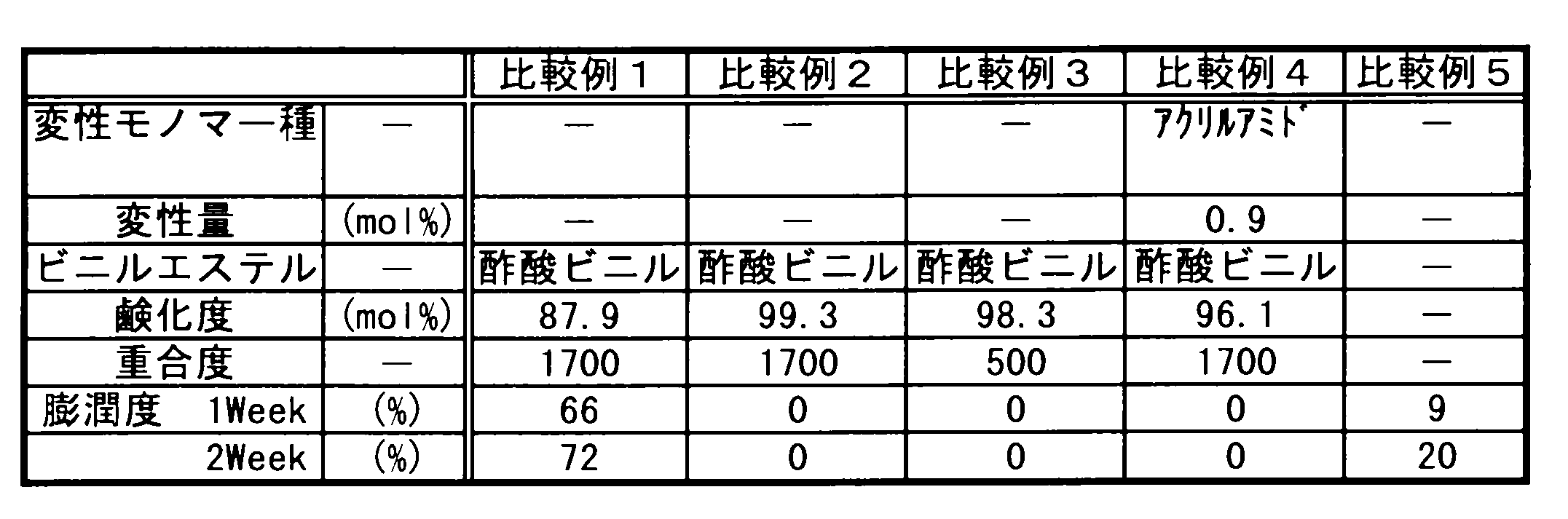
<比較例5>
PVDFを樹脂バインダーとして12%となるようにNMPに溶解した溶液を、乾燥・熱処理後の膜厚が約80μmとなるように、PETフィルム上に均一に流延した後、150℃の熱板上で3時間常圧乾燥した後、PETフィルムから剥離してフィルムを得た。作製したフィルムの耐電解液性の評価結果を、「表2」に示す。
PVDFを樹脂バインダーとして12%となるようにNMPに溶解した溶液を、乾燥・熱処理後の膜厚が約80μmとなるように、PETフィルム上に均一に流延した後、150℃の熱板上で3時間常圧乾燥した後、PETフィルムから剥離してフィルムを得た。作製したフィルムの耐電解液性の評価結果を、「表2」に示す。
2.正極及び二次電池の製造と性能評価
実施例10~20及び比較例6~12では、実施例1~9及び比較例1~5で製造した樹脂バインダーを用いてスラリーを調製し、活物質の分散性を評価した。さらに、調製したスラリーを用いて正電極及びリチウム二次電池を作製し、合剤層の付着性、正極の鉛筆硬度、電池性能の評価を行った。
実施例10~20及び比較例6~12では、実施例1~9及び比較例1~5で製造した樹脂バインダーを用いてスラリーを調製し、活物質の分散性を評価した。さらに、調製したスラリーを用いて正電極及びリチウム二次電池を作製し、合剤層の付着性、正極の鉛筆硬度、電池性能の評価を行った。
<実施例10>
実施例1で得た樹脂バインダー5部を水100部に溶解したものに、平均粒径D502μmのLiFePO4を93.1部、導電助剤1.9部を混合し、スラリーを調製した。調製したスラリーについて、以下の方法により耐電解液性を評価した。
実施例1で得た樹脂バインダー5部を水100部に溶解したものに、平均粒径D502μmのLiFePO4を93.1部、導電助剤1.9部を混合し、スラリーを調製した。調製したスラリーについて、以下の方法により耐電解液性を評価した。
(B)分散性の評価
調製したスラリーを20μで正極集電体(アルミニウム箔)に塗工し、粗い粒子で塗工面に筋状の跡が付くものを「不良」、筋状の跡が付かないものを「良」、若干跡が付くものを「可」として、目視評価を行った。
調製したスラリーを20μで正極集電体(アルミニウム箔)に塗工し、粗い粒子で塗工面に筋状の跡が付くものを「不良」、筋状の跡が付かないものを「良」、若干跡が付くものを「可」として、目視評価を行った。
次に、厚み20μmの正極集電体(アルミニウム箔)の両面に、調製したスラリーを合剤塗布量が片面ずつ140g/m2となるように塗布し、これを60℃で乾燥して合剤層を形成した。これをロールプレス機で合剤層の厚さが両面で148μmになるようにプレスし、54mm幅に切断して短冊状の合剤シートを作製した。合剤シートの端部にアルミニウム製の集電体タブを超音波溶着した後、残留溶媒や吸着水分といった揮発成分を完全に除去するため、120℃で14時間真空乾燥して正極を得た。作製した正極について、以下の方法により、合剤層の付着性と鉛筆強度を評価した。
(C)付着性の評価
作製した電極を用い、JIS K-5600に準じ、カット間隔2mmで格子パターン25マスのクロスカット法試験により、集電体と活物質間の付着性を評価した。評価は0~5の6段階により行い、数字が少ないものほど結着性が良好であることを示す。
作製した電極を用い、JIS K-5600に準じ、カット間隔2mmで格子パターン25マスのクロスカット法試験により、集電体と活物質間の付着性を評価した。評価は0~5の6段階により行い、数字が少ないものほど結着性が良好であることを示す。
(D)鉛筆硬度の評価
作製した電極を用い、JIS K-5600-5-4に準じ、引っかき硬度(鉛筆法)を6Bから6Hの14段階で評価した。
作製した電極を用い、JIS K-5600-5-4に準じ、引っかき硬度(鉛筆法)を6Bから6Hの14段階で評価した。
続いて、作製した電極を用いてリチウム二次電池を作製した。負極活物質として人造黒鉛を98部、SBR/CMC系バインダー樹脂組成物を2部混合し、必要に応じて水を足しながら混練して負極合剤スラリーを調製した。
厚み10μmの集電体(銅箔)の両面に、負極合剤スラリーを合剤塗布量が片面ずつ70g/m2となるように塗布し、60℃で乾燥して合剤層を形成した。次いで、これをロールプレス機で銅箔負極集電体上に両面で90μmの負極活物質層となるように圧延し、56mm幅に切断して短細状の合剤シートを作製した。合剤シートの端部にニッケル製の集電体タブを超音波溶着した後、残留溶媒や吸着水分といった揮発成分を完全に除去するため、120℃で14時間真空乾燥して負極を得た。
得られた負極と正極とを組合せ、厚み25μm、幅60mmのポリエチレン微多孔膜セパレーターを介して捲回し、スパイラル状の捲回群を作製した後、これを電池缶に挿入し、予め負極集電体の銅箔に溶接しておいたニッケルタブ端子を電池缶底に溶接し、正極集電体のアルミニウム箔に溶接したアルミニウムタブ端子を蓋に溶接した。次いで、非水電解液(1Mの濃度で六フッ化リン酸リチウムを溶解したエチレンカーボネート/ジメチルカーボネート/ジエチルカーボネート=25/60/15(重量比)混合液)を電池容器に5ml注入した後、この部分をかしめて密閉し、直径18mm、高さ65mmの円筒形のリチウム二次電池(3.4V-940mAh)を作製した。作製した二次電池について、以下の方法により電池性能を評価した。
(E)初回充放電効率の評価
作製した電池を、25℃において4.0V、0.2C(188mA)制限の定電流定電圧充電をした後、0.2Cの定電流で2.0Vまで放電した。このときの充電容量に対する放電容量を初回充放電効率とした。なお、1時間率の放電容量による定格容量を1時間で放電する電流値を1Cとする。
作製した電池を、25℃において4.0V、0.2C(188mA)制限の定電流定電圧充電をした後、0.2Cの定電流で2.0Vまで放電した。このときの充電容量に対する放電容量を初回充放電効率とした。なお、1時間率の放電容量による定格容量を1時間で放電する電流値を1Cとする。
(F)高率放電容量維持率の評価
次いで、放電電流を0.2C、1Cと変化させ、各放電電流に対する放電容量を測定した。各測定における回復充電は4.0V(1Cカット)の定電流定電圧充電を行った。そして、0.2C放電時に対する1C放電時の高率放電容量維持率を計算した。
次いで、放電電流を0.2C、1Cと変化させ、各放電電流に対する放電容量を測定した。各測定における回復充電は4.0V(1Cカット)の定電流定電圧充電を行った。そして、0.2C放電時に対する1C放電時の高率放電容量維持率を計算した。
(13)サイクル寿命の評価
環境温度25℃にて、充電電圧4.0V、1Cの定電流定電圧充電と、放電終止電圧2.0Vの1Cの定電流放電を行った。充電及び放電のサイクルを繰り返し行い、1サイクル目の放電容量に対する500サイクル目の放電容量の比率を求めてサイクル容量維持率とした。
環境温度25℃にて、充電電圧4.0V、1Cの定電流定電圧充電と、放電終止電圧2.0Vの1Cの定電流放電を行った。充電及び放電のサイクルを繰り返し行い、1サイクル目の放電容量に対する500サイクル目の放電容量の比率を求めてサイクル容量維持率とした。
合剤層の付着性、正極の鉛筆硬度、電池性能の評価結果を、「表3」に示す。

<実施例11~20>
樹脂バインダー種、各種正極剤の混合比をそれぞれ「表3」に示すように変えた以外は、実施例10と同様にしてスラリー、正極、2次電池を作成し、合剤層の付着性、正極の鉛筆硬度、電池性能の評価を行った。評価結果を、「表3」に示す。
樹脂バインダー種、各種正極剤の混合比をそれぞれ「表3」に示すように変えた以外は、実施例10と同様にしてスラリー、正極、2次電池を作成し、合剤層の付着性、正極の鉛筆硬度、電池性能の評価を行った。評価結果を、「表3」に示す。
<比較例6~12>
樹脂バインダー種、溶媒種、各種正極剤の混合比をそれぞれ「表4」に示すように変えた以外は、実施例10と同様にしてスラリー、正極、2次電池を作成し、合剤層の付着性、正極の鉛筆硬度、電池性能の評価を行った。評価結果を、「表4」に示す。なお、比較例7と8では、スラリーを調製する際の活物質の分散性が悪く電池を作ることが出来なかった。
樹脂バインダー種、溶媒種、各種正極剤の混合比をそれぞれ「表4」に示すように変えた以外は、実施例10と同様にしてスラリー、正極、2次電池を作成し、合剤層の付着性、正極の鉛筆硬度、電池性能の評価を行った。評価結果を、「表4」に示す。なお、比較例7と8では、スラリーを調製する際の活物質の分散性が悪く電池を作ることが出来なかった。

「表3」及び「表4」に示すように、実施例に係る2次電池では、設計計算通りに85%程度の初回充放電効率が確保されている。また、高率放電容量維持率についても、すべて100%となり劣化はなかった。さらに、サイクル寿命についても、すべて90%以上となり劣化はなかった。
これに対して、比較例に係る2次電池では、比較例9,10,11で初回充放電効率の低下がみられた。比較例の9,10では、PVAの変性モノマーを含有しなかったり、モノマーがアクリルアミドであることより初充電中に電解液中のリチウムイオンと反応してリチウム酸化物や水酸化物を生成したり、またはプロトンとリチウムの置換反応により放電に関与できなくなって効率が低下したものと思われる。また、比較例11では、PVDFバインダーの添加量が少なく、正極合剤間またはアルミ箔集電体との密着性が低下して電極板としての電子伝導抵抗が増加した結果、正極の抵抗増大として放電時の容量が特に低下して効率が低下したものと考えられる。
また、比較例に係る2次電池では、比較例6,11で高率放電容量維持率の低下がみられた。比較例6,11では、PVAバインダーの鹸化度が低いために電解液による膨潤が多く、密着力低下による電極抵抗増加を誘起したためと、PVDFバインダー量が少ないために同様に電極抵抗増加を招いたことによって放電特性が低下したものといえる。
さらに、比較例に係る2次電池では、比較例6,9,10,11,12でサイクル寿命の低下がみられた。これは、鹸化度の低いPVAやPVDFの電解液の膨潤によって電解液が枯渇したこと、または密着性低下による電極抵抗増加を招いたことで容量劣化したためと考えられる。また、比較例9,10では、充放電サイクルとともにリチウム酸化物や水酸化物の抵抗被膜が正極材表面に生成し、結果として充放電出来にくくなったと考えられる。
以上の結果は、正極活物質としてオリビン形リン酸鉄リチウムを用いた場合以外に、マンガン系複合リチウム酸化物やコバルト複合酸化物、またニッケル系複合酸化物を用いた場合にも同様であった。
本発明に係るリチウムイオン二次電池は、製造工程上の問題が少ない。また、電池のエネルギー容量の低下が少なく、高電圧下で分解が起こり難いため、例えば電気自動車用等の大型リチウム電池として採用され得る。
Claims (6)
- リン酸鉄リチウムと導電材と樹脂バインダーとしての炭化水素ビニルエーテル変性ポリビニルアルコールとを含む混合物からなる正極合剤層が正極集電体上に積層されてなる正極と、負極と、セパレーターと、リチウム塩の支持電解質を含む非水溶媒と、を有するリチウムイオン二次電池。
- 炭化水素ビニルエーテル変性ポリビニルアルコールが、分子内に炭素数5~30の炭化水素基を有するビニルエーテルと、ビニルエステル単位を有するモノマーとの共重合物であり、
変性量がエステル単位100モル%に対して0.01~10モル%、重合度が300~5000、鹸化度が93~99.99モル%であることを特徴とする請求項1記載のリチウムイオン二次電池。 - 樹脂バインダーの量が、リン酸鉄リチウム100質量部に対して、2~10質量部であることを特徴とする請求項1又は2に記載のリチウムイオン二次電池。
- 負極活物質が、リチウム金属、リチウム合金又はリチウムイオンを吸蔵及び放出し得る炭素質材であることを特徴とする請求項1~3のいずれか一項に記載のリチウムイオン二次電池。
- リン酸鉄リチウムと導電材と樹脂バインダーとしての炭化水素ビニルエーテル変性ポリビニルアルコールと、を水中に溶解・分散させた分散溶液を、正極集電体上に塗布、乾燥し、正極合剤層を積層する工程を含むリチウムイオン二次電池の製造方法。
- さらに、分子内に炭素数5~30の炭化水素基を有するビニルエーテルと、ビニルエステル単位を有するモノマーとを共重合し、
変性量がエステル単位100モル%に対して0.01~10モル%、重合度が300~5000の共重合物とし、
鹸化触媒にて、鹸化度93~99.99モル%となるようエステル単位を加水分解及び/又は加アルコール分解して、炭化水素ビニルエーテル変性ポリビニルアルコールを得る工程を含む請求項5記載のリチウムイオン二次電池の製造方法。
Applications Claiming Priority (2)
| Application Number | Priority Date | Filing Date | Title |
|---|---|---|---|
| JP2009062356A JP2010218793A (ja) | 2009-03-16 | 2009-03-16 | リチウムイオン二次電池及びその製造方法 |
| JP2009-062356 | 2009-03-16 |
Publications (1)
| Publication Number | Publication Date |
|---|---|
| WO2010106877A1 true WO2010106877A1 (ja) | 2010-09-23 |
Family
ID=42739542
Family Applications (1)
| Application Number | Title | Priority Date | Filing Date |
|---|---|---|---|
| PCT/JP2010/052674 Ceased WO2010106877A1 (ja) | 2009-03-16 | 2010-02-23 | リチウムイオン二次電池及びその製造方法 |
Country Status (2)
| Country | Link |
|---|---|
| JP (1) | JP2010218793A (ja) |
| WO (1) | WO2010106877A1 (ja) |
Cited By (7)
| Publication number | Priority date | Publication date | Assignee | Title |
|---|---|---|---|---|
| CN102290569A (zh) * | 2011-07-25 | 2011-12-21 | 青岛海霸能源集团有限公司 | 60ah磷酸铁锂方形电池及其制作工艺 |
| CN102290568A (zh) * | 2011-07-25 | 2011-12-21 | 青岛海霸能源集团有限公司 | 100ah磷酸铁锂方形电池及其制作工艺 |
| CN102623699A (zh) * | 2012-04-19 | 2012-08-01 | 日照华轩新能源有限公司 | 一种高性能磷酸亚铁锂的合成方法 |
| JP2012174465A (ja) * | 2011-02-21 | 2012-09-10 | Denso Corp | 非水電解液二次電池 |
| JP2016171074A (ja) * | 2015-03-13 | 2016-09-23 | 日本ゼオン株式会社 | リチウムイオン二次電池電極用バインダー組成物、リチウムイオン二次電池電極用スラリー組成物、リチウムイオン二次電池用電極およびリチウムイオン二次電池 |
| JP2016219197A (ja) * | 2015-05-19 | 2016-12-22 | 協立化学産業株式会社 | 集電体用コート剤組成物、蓄電デバイス用電極板及び蓄電デバイス |
| EP4446390A4 (en) * | 2022-01-14 | 2025-04-02 | LG Chem, Ltd. | Adhesion-strengthening composition, current collector comprising same, positive electrode including same current collector, method for manufacturing same positive electrode, and lithium secondary battery comprising same positive electrode |
Families Citing this family (9)
| Publication number | Priority date | Publication date | Assignee | Title |
|---|---|---|---|---|
| JP5670286B2 (ja) * | 2011-09-20 | 2015-02-18 | 株式会社クラレ | 電池用電極およびそれを用いたリチウムイオン二次電池 |
| CN102751536A (zh) * | 2012-07-10 | 2012-10-24 | 上海索锂科技有限公司 | 一种大容量汽车用磷酸铁锂锂离子电池的制备方法 |
| JP6124062B2 (ja) * | 2013-04-15 | 2017-05-10 | 日本電気硝子株式会社 | 蓄電デバイス用正極材料、およびその製造方法 |
| CN103280550B (zh) * | 2013-05-28 | 2015-07-08 | 山东精工电子科技有限公司 | 一种锂铁扣式电池正极片制备方法 |
| WO2015016283A1 (ja) * | 2013-08-01 | 2015-02-05 | 協立化学産業株式会社 | 非水系蓄電素子用結着剤及び非水系蓄電素子 |
| CN105637686B (zh) * | 2013-10-09 | 2018-05-08 | 电化株式会社 | 正极用粘结剂组合物、正极用浆料、正极及锂离子二次电池 |
| JP6994155B2 (ja) | 2018-01-10 | 2022-01-14 | トヨタ自動車株式会社 | 非水電解液リチウム二次電池 |
| KR102884157B1 (ko) * | 2019-01-11 | 2025-11-14 | 주식회사 쿠라레 | 비수 전해질 전지 전극 바인더, 비수 전해질 전지 전극 바인더 용액, 비수 전해질 전지 전극 슬러리, 비수 전해질 전지 전극 및 비수 전해질 전지 |
| JP7683995B2 (ja) * | 2022-01-13 | 2025-05-27 | エルジー エナジー ソリューション リミテッド | 非水電解質用添加剤を含む非水電解質およびそれを含むリチウム二次電池 |
Citations (4)
| Publication number | Priority date | Publication date | Assignee | Title |
|---|---|---|---|---|
| JPH01219723A (ja) * | 1988-02-26 | 1989-09-01 | Kuraray Co Ltd | 微粒子分散体及びそれを用いる電極の製法 |
| JPH11512869A (ja) * | 1995-09-29 | 1999-11-02 | エナージェティクス システムズ コーポレイション | 導電性セラミック繊維を用いた電気エネルギー装置 |
| JPH11329437A (ja) * | 1998-05-15 | 1999-11-30 | Shin Etsu Chem Co Ltd | 水素吸蔵合金電極及びその製造方法 |
| JP2006107959A (ja) * | 2004-10-06 | 2006-04-20 | Nippon Zeon Co Ltd | 電極及びその製造方法 |
-
2009
- 2009-03-16 JP JP2009062356A patent/JP2010218793A/ja active Pending
-
2010
- 2010-02-23 WO PCT/JP2010/052674 patent/WO2010106877A1/ja not_active Ceased
Patent Citations (4)
| Publication number | Priority date | Publication date | Assignee | Title |
|---|---|---|---|---|
| JPH01219723A (ja) * | 1988-02-26 | 1989-09-01 | Kuraray Co Ltd | 微粒子分散体及びそれを用いる電極の製法 |
| JPH11512869A (ja) * | 1995-09-29 | 1999-11-02 | エナージェティクス システムズ コーポレイション | 導電性セラミック繊維を用いた電気エネルギー装置 |
| JPH11329437A (ja) * | 1998-05-15 | 1999-11-30 | Shin Etsu Chem Co Ltd | 水素吸蔵合金電極及びその製造方法 |
| JP2006107959A (ja) * | 2004-10-06 | 2006-04-20 | Nippon Zeon Co Ltd | 電極及びその製造方法 |
Cited By (8)
| Publication number | Priority date | Publication date | Assignee | Title |
|---|---|---|---|---|
| JP2012174465A (ja) * | 2011-02-21 | 2012-09-10 | Denso Corp | 非水電解液二次電池 |
| CN102290569A (zh) * | 2011-07-25 | 2011-12-21 | 青岛海霸能源集团有限公司 | 60ah磷酸铁锂方形电池及其制作工艺 |
| CN102290568A (zh) * | 2011-07-25 | 2011-12-21 | 青岛海霸能源集团有限公司 | 100ah磷酸铁锂方形电池及其制作工艺 |
| CN102623699A (zh) * | 2012-04-19 | 2012-08-01 | 日照华轩新能源有限公司 | 一种高性能磷酸亚铁锂的合成方法 |
| CN102623699B (zh) * | 2012-04-19 | 2014-04-09 | 日照华轩新能源有限公司 | 一种高性能磷酸亚铁锂的合成方法 |
| JP2016171074A (ja) * | 2015-03-13 | 2016-09-23 | 日本ゼオン株式会社 | リチウムイオン二次電池電極用バインダー組成物、リチウムイオン二次電池電極用スラリー組成物、リチウムイオン二次電池用電極およびリチウムイオン二次電池 |
| JP2016219197A (ja) * | 2015-05-19 | 2016-12-22 | 協立化学産業株式会社 | 集電体用コート剤組成物、蓄電デバイス用電極板及び蓄電デバイス |
| EP4446390A4 (en) * | 2022-01-14 | 2025-04-02 | LG Chem, Ltd. | Adhesion-strengthening composition, current collector comprising same, positive electrode including same current collector, method for manufacturing same positive electrode, and lithium secondary battery comprising same positive electrode |
Also Published As
| Publication number | Publication date |
|---|---|
| JP2010218793A (ja) | 2010-09-30 |
Similar Documents
| Publication | Publication Date | Title |
|---|---|---|
| WO2010106877A1 (ja) | リチウムイオン二次電池及びその製造方法 | |
| CN108140810B (zh) | 二次电池用负极 | |
| KR101902071B1 (ko) | 음극 활물질 입자 및 이의 제조방법 | |
| CN105637686B (zh) | 正极用粘结剂组合物、正极用浆料、正极及锂离子二次电池 | |
| CN111640912A (zh) | 一种正极极片及其制备方法和锂离子二次电池 | |
| CN111771300A (zh) | 包含硅基化合物的多层阳极和包括该多层阳极的锂二次电池 | |
| JP7062210B2 (ja) | 二次電池 | |
| KR101645773B1 (ko) | 전극 활물질 슬러리 및 이를 포함하는 리튬 이차 전지 | |
| KR102194326B1 (ko) | 전극 시트의 제조 방법 | |
| JP2012119091A (ja) | 非水系電解液、電極、ならびに、当該非水系電解液及び電極を備える電気化学デバイス | |
| CN111971824A (zh) | 二次电池用负极活性材料、包含其的负极以及其制造方法 | |
| JP4852824B2 (ja) | リチウム二次電池用負極、その製造方法及びリチウム二次電池 | |
| CN116636029A (zh) | 用于可充电电池的电极粘合剂组合物和包含该电极粘合剂组合物的电极混合物 | |
| JP2022536290A (ja) | リチウムイオン電池用のその場重合されたポリマー電解質 | |
| JP5365668B2 (ja) | リチウム二次電池及びその負極の製造方法 | |
| JP7244626B2 (ja) | リチウム二次電池用正極活物質、その製造方法及びこれを含むリチウム二次電池 | |
| JP2008287932A (ja) | リチウムイオンポリマー電池 | |
| JP2019215961A (ja) | 特定添加剤を含んだ二次電池用非水系電解質及びこれを用いた二次電池 | |
| WO2025051071A1 (zh) | 负极片和钠离子电池 | |
| CN105047934A (zh) | 二次电池用负极粘结剂、二次电池用电极 | |
| JP5418828B2 (ja) | リチウム二次電池とその製造方法 | |
| JP5271751B2 (ja) | リチウムイオン二次電池 | |
| CN116235334A (zh) | 具有减少的气体产生量的牺牲正极材料和包含其的锂二次电池 | |
| JPWO2016021443A1 (ja) | リチウムイオン電池の負極の製造方法、並びにリチウムイオン電池の製造方法 | |
| JP2016076311A (ja) | 電極用バインダー組成物 |
Legal Events
| Date | Code | Title | Description |
|---|---|---|---|
| 121 | Ep: the epo has been informed by wipo that ep was designated in this application |
Ref document number: 10753372 Country of ref document: EP Kind code of ref document: A1 |
|
| NENP | Non-entry into the national phase |
Ref country code: DE |
|
| 122 | Ep: pct application non-entry in european phase |
Ref document number: 10753372 Country of ref document: EP Kind code of ref document: A1 |