WO2010106792A1 - 酸素の検出方法,空気リークの判別方法,ガス成分検出装置,及び真空処理装置 - Google Patents
酸素の検出方法,空気リークの判別方法,ガス成分検出装置,及び真空処理装置 Download PDFInfo
- Publication number
- WO2010106792A1 WO2010106792A1 PCT/JP2010/001860 JP2010001860W WO2010106792A1 WO 2010106792 A1 WO2010106792 A1 WO 2010106792A1 JP 2010001860 W JP2010001860 W JP 2010001860W WO 2010106792 A1 WO2010106792 A1 WO 2010106792A1
- Authority
- WO
- WIPO (PCT)
- Prior art keywords
- filament
- oxygen
- vacuum processing
- gas component
- filament current
- Prior art date
- Legal status (The legal status is an assumption and is not a legal conclusion. Google has not performed a legal analysis and makes no representation as to the accuracy of the status listed.)
- Ceased
Links
Images


Classifications
-
- G—PHYSICS
- G01—MEASURING; TESTING
- G01N—INVESTIGATING OR ANALYSING MATERIALS BY DETERMINING THEIR CHEMICAL OR PHYSICAL PROPERTIES
- G01N27/00—Investigating or analysing materials by the use of electric, electrochemical, or magnetic means
- G01N27/62—Investigating or analysing materials by the use of electric, electrochemical, or magnetic means by investigating the ionisation of gases, e.g. aerosols; by investigating electric discharges, e.g. emission of cathode
- G01N27/64—Investigating or analysing materials by the use of electric, electrochemical, or magnetic means by investigating the ionisation of gases, e.g. aerosols; by investigating electric discharges, e.g. emission of cathode using wave or particle radiation to ionise a gas, e.g. in an ionisation chamber
- G01N27/66—Investigating or analysing materials by the use of electric, electrochemical, or magnetic means by investigating the ionisation of gases, e.g. aerosols; by investigating electric discharges, e.g. emission of cathode using wave or particle radiation to ionise a gas, e.g. in an ionisation chamber and measuring current or voltage
-
- G—PHYSICS
- G01—MEASURING; TESTING
- G01M—TESTING STATIC OR DYNAMIC BALANCE OF MACHINES OR STRUCTURES; TESTING OF STRUCTURES OR APPARATUS, NOT OTHERWISE PROVIDED FOR
- G01M3/00—Investigating fluid-tightness of structures
- G01M3/02—Investigating fluid-tightness of structures by using fluid or vacuum
- G01M3/04—Investigating fluid-tightness of structures by using fluid or vacuum by detecting the presence of fluid at the leakage point
- G01M3/20—Investigating fluid-tightness of structures by using fluid or vacuum by detecting the presence of fluid at the leakage point using special tracer materials, e.g. dye, fluorescent material, radioactive material
- G01M3/202—Investigating fluid-tightness of structures by using fluid or vacuum by detecting the presence of fluid at the leakage point using special tracer materials, e.g. dye, fluorescent material, radioactive material using mass spectrometer detection systems
Definitions
- the present invention relates to an oxygen detection method, an air leak determination method, a gas component detection device, and a vacuum processing device.
- the present invention relates to a method for efficiently detecting oxygen in a vacuum processing chamber by controlling and measuring a filament current using an ionization vacuum gauge or a mass spectrometer, a method for determining an air leak using this detection method,
- the present invention relates to a gas component detection apparatus that performs such a detection method or discrimination method, and a vacuum processing apparatus including the component detection apparatus.
- FIG. 6 is a schematic diagram showing the configuration of a conventional hot cathode ionization vacuum gauge.
- the conventional hot cathode ionization vacuum gauge 200 one end of the filament 201 is connected to the plus terminal of the variable power source 204.
- the other end of the filament 201 is connected to the negative terminal of the variable power source 204 and is grounded via the emission ammeter 208.
- the filament 201 is disposed in a vacuum atmosphere together with the grid 202 and the ion collector 203.
- the grid 202 is connected to the plus terminal of the grid bias power source 205.
- a filament current If flows through the filament 201, the filament 201 generates heat, and thermoelectrons 210 are emitted.
- the thermoelectrons 210 emitted from the filament 201 reach the grid 202, and an emission current Ie is generated.
- the thermoelectrons 210 collide with the gas molecules, whereby the gas molecules are ionized, and positive ions 211 are generated.
- the positive ions 211 generated at this time are collected in the ion collector 203 to generate an ion current Ii.
- the emission current Ie and the ion current Ii the density of the gas, that is, the degree of vacuum is measured.
- Equation (1) holds for the pressure P, the ion current Ii, and the emission current Ie.
- S represents a sensitivity coefficient.
- the pressure P can be calculated by changing the output value of the variable power source 204 so that the emission current Ie is constant and controlling the filament current If.
- Patent Document 1 a method for measuring the filament current value and predicting the filament life using this value is known (for example, see Patent Document 1). Further, a method for protecting the filament breakage (see, for example, Patent Document 2) is known. Further, a method of using a measured value of a current applied to a filament to calculate a correct value of sensitivity and display pressure (see, for example, Patent Document 3) is known.
- the present invention has been made in view of the above circumstances, and by detecting oxygen in a vacuum processing chamber using an ionization vacuum gauge or mass spectrometer used in many vacuum processing apparatuses, a detection unit is newly provided. It is an object of the present invention to provide a method for detecting oxygen in a vacuum processing chamber that can be reduced in cost, and can be reduced in installation space.
- the oxygen detection method provides a grid, an ion collector, and a filament in which an oxide is formed on a metal surface, and the emission current is constant.
- the filament current flowing through the filament is controlled so that heat electrons are emitted by the heat generated by energizing the filament current, gas is ionized to generate ions, the ions are captured by the ion collector, and the filament current
- the oxygen present in the vacuum processing chamber is detected by measuring the value.
- the method for detecting oxygen according to the first aspect of the present invention preferably uses an ionization vacuum gauge including the filament and the grid.
- the oxygen detection method of the first aspect of the present invention preferably uses a mass spectrometer including the filament and the grid.
- the metal is iridium and the oxide is yttrium oxide.
- the air leak determination method of the second aspect of the present invention uses the oxygen detection method of the first aspect to detect the presence or absence of air leak.
- the gas component detection apparatus according to the third aspect of the present invention performs the oxygen detection method according to the first aspect.
- the gas component detection device according to the third aspect of the present invention preferably includes an output unit that outputs a filament current value, a pressure value, and an oxygen detection signal to the outside.
- the gas component detection device performs the air leak determination method according to the second aspect.
- the gas component detection device preferably includes an output unit that outputs a filament current value, a pressure value, and an oxygen detection signal to the outside.
- the vacuum processing apparatus includes the gas component detection apparatus according to the third aspect.
- the vacuum processing apparatus includes the gas component detection apparatus according to the fourth aspect.
- a filament, an ion collector, and a filament in which an oxide is disposed on the surface of a metal (base material) is used, and the filament flows through the filament so that the emission current is constant.
- the current is controlled and the filament current is measured.
- oxygen in the vacuum processing chamber can be detected, and the presence or absence of air leakage can also be detected.
- the hot cathode ionization vacuum gauge or mass spectrometer used in many vacuum processing apparatuses can be used to detect oxygen in the vacuum processing chamber and determine the presence or absence of air leaks. Thereby, it is not necessary to newly add a detection unit, cost can be reduced, and installation space can be reduced.
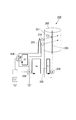
- FIG. 1 It is a schematic diagram which shows the structure of the gas component detection apparatus which concerns on this invention.
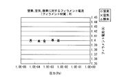
- the conventional filament it is a figure which shows the relationship between the pressure when various gas is introduce
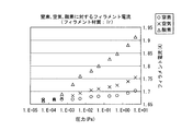
- the filament which concerns on this invention it is a figure which shows the relationship between the pressure when various gas is introduce
- FIG. 1 is a schematic diagram showing a basic configuration of a gas component detection apparatus 100 (ionization vacuum gauge) using an oxygen detection method and an air leak determination method according to the present invention.
- the gas component detection apparatus 100 includes a filament 101, a grid 102, an ion collector 103, a variable power source 104, a grid bias power source 105, a filament ammeter 107, an emission ammeter 108, and an ion ammeter 109.
- the filament 101, the grid 102, and the ion collector 103 are arranged in an atmosphere in a vacuum processing chamber of a vacuum processing apparatus.
- one end of the filament 101 is connected to the plus terminal of the variable power source 104 via the filament ammeter 107.
- the filament ammeter 107 and the ion ammeter 109 are electrically connected to an output unit 50 that outputs a signal to the measuring device 51 or the control device 52.
- the values measured by the filament ammeter 107 and the ion ammeter 109 are output to the measuring device 51 or the control device 52 through the output unit 50.
- the measuring device 51 or the control device 52 constitutes a part of the vacuum processing apparatus.
- the measuring device 51 or the control device 52 includes a storage unit that stores values measured by the filament ammeter 107 and the ion ammeter 109.
- the storage unit stores the pressure and the filament current value as described below. According to such a configuration, the pressure in the vacuum processing chamber and the filament current value when various gases are introduced into the vacuum processing chamber can be recorded and stored.
- FIG. 1 shows a gas component detection apparatus 100 having an ionization vacuum gauge, but the same configuration is adopted even when a mass spectrometer is used instead of the ionization vacuum gauge.
- Example 1 In this experimental example, a gas was introduced into the vacuum processing chamber in a state where a high vacuum atmosphere was obtained in the vacuum processing chamber, and the relationship between the measured pressure P and the filament current If was examined.
- the gas nitrogen used for normal venting operation, air detected separately from nitrogen, and oxygen were selected. 2 and 3 described below, the horizontal axis indicates the pressure P, and the vertical axis indicates the filament current If.
- FIG. 2 shows a pressure P and a filament current when nitrogen, air, and oxygen are introduced using a gas component detection device 100 in which tungsten (W), which has been conventionally used as a material for the filament 101, is used. The result of comparing with If is shown. As shown in FIG. 2, no difference among nitrogen, air, and oxygen can be found in the relationship between the pressure P and the filament current If. Therefore, the type of gas introduced into the vacuum processing chamber cannot be determined.
- W tungsten
- FIG. 3 shows that nitrogen, air, and oxygen are introduced using a gas component detection device 100 in which a filament 101 having a structure in which an oxide is coated on the surface of a metal base material is used.
- the result of comparing the pressure P and the filament current If is shown.
- the filament 101 in which the surface of the iridium (Ir) base material is coated with yttrium oxide (Y 2 O 3 ) is used, and the result obtained by performing the same experiment as in FIG. 2 is shown.
- thermo electron emission current density J the number of electrons jumping out from a metal surface per unit area and unit time (thermal electron emission current density) J is expressed by the following equation (2) (Richardson-Dashman equation).
- k is the Boltzmann constant
- ⁇ is the work function
- A is the Richardson constant
- A 4 ⁇ mk 2 e / h 3
- m and e are the mass and charge of electrons
- h is the Planck constant
- T is the temperature.
- FIG. 3 shows that the filament current If measured when oxygen is introduced is larger than the filament current If measured when air is introduced (result 2). Even under the same pressure, the filament current If of oxygen becomes larger than the filament current If of air. The reason for this is that when oxygen is adsorbed on the filament surface, electrons are taken from the filament surface, and oxygen negative ions are adsorbed on the filament surface, thereby increasing the work function and consequently the filament for obtaining the specified emission current. It is considered that the current increases (temperature increases).
- the pressure and filament current value when nitrogen is introduced into the vacuum processing chamber are recorded and stored in advance as reference values. Thereafter, the filament current value is measured when a gas of unknown type is introduced into the vacuum processing chamber, and the presence of oxygen or air can be detected by comparing the reference value with the measured value. . That is, a reference nitrogen gas (reference gas, first gas) is introduced into the vacuum processing chamber, and the filament current (first filament current) is measured by the above method. Thereafter, the measured filament current value is stored as a reference value. Thereafter, a gas of unknown type (measurement target gas, second gas) is introduced into the vacuum processing chamber, and the filament current value (second filament current) is measured.
- a reference nitrogen gas reference gas
- the filament current first filament current
- the reference value is compared with the filament current value of the gas whose type is unknown. This makes it possible to detect that the gas that is unknown in the vacuum processing chamber is oxygen or air. Therefore, the method of the present invention can be effectively used as a method for discriminating air leakage in the vacuum processing chamber.
- the type existing in the vacuum processing chamber is unknown when it is determined that the filament current value of the gas introduced into the vacuum processing chamber is equal to or greater than a specified value at a predetermined pressure. It may be determined that the gas is oxygen or air. Specifically, a characteristic (first characteristic) indicating the relationship between pressure and filament current when oxygen is introduced into the vacuum processing chamber is stored, and pressure and filament when air is introduced into the vacuum processing chamber A characteristic (second characteristic) indicating the relationship with the current is stored. That is, the relationship between the pressure and the filament current shown in FIG. 3 is stored. As a result, a prescribed value for oxygen (first prescribed value) and a prescribed value for air (second prescribed value) are determined.
- the gas exists in the vacuum processing chamber. It is determined that the gas whose type is unknown is oxygen. In addition, when it is determined that the measured filament current value is equal to or greater than the second specified value at a predetermined pressure, it is determined that the gas that is unknown in the vacuum processing chamber is air.
- the filament current value (first filament current) measured when nitrogen is introduced into the vacuum processing chamber is determined as a reference value.
- the first specified value (oxygen) and the second specified value (air) are determined based on the first characteristic and the second characteristic.
- a first difference value obtained by subtracting the reference value from the first specified value and a second difference value obtained by subtracting the reference value from the second specified value are calculated and stored.
- the type existing in the vacuum processing chamber is unknown. It is determined that a certain gas is oxygen.
- the type existing in the vacuum processing chamber is unknown. It is determined that the gas is air.
- a film forming process may be performed in an atmosphere in which oxygen is introduced in addition to argon. Also in this case, the pressure and the filament current value when argon and oxygen used in the film forming process are introduced into the vacuum processing chamber are recorded and stored as reference values.
- FIG. 4 is a diagram showing the change over time of the pressure and the filament current value measured by the method described above.
- the horizontal axis indicates time
- the vertical axis indicates the filament current If and the differential value of the filament current.
- the filament current value increases at the time when about 26 seconds have passed.
- the filament current value changes in the differential value of the filament current value. That is, when it is detected that the pressure measured by the ionization vacuum gauge does not change and the differential value of the filament current is equal to or higher than the specified value, it can be determined that air exists in the vacuum processing chamber. That is, it can be determined that an air leak has occurred suddenly. In this case, since it is not necessary to record and store the reference value when nitrogen is introduced into the vacuum processing chamber in advance, the adverse effect of gradually increasing the filament current due to filament deterioration is reduced.
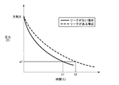
- FIG. 5 is a diagram showing the relationship between the time required for pressure reduction and the pressure when the pressure in the vacuum processing chamber is reduced from the atmospheric pressure toward the vacuum. It is determined based on the time required to reach the measurable pressure p1 from the start of the pressure reduction. If there is no air leak in the vacuum processing chamber, the time t1 (reference time) for turning on the filament and the filament current a1 (reference current) at time t1 are recorded in advance. As the number of processes using the vacuum processing chamber (for example, a film forming process) increases, and as the number of times of maintenance of the vacuum processing chamber increases, the possibility of leakage occurring in the vacuum processing chamber increases. Therefore, it is necessary to detect the presence or absence of a leak.
- Experimental example 3 shows an example of detecting the presence or absence of a leak in such a case.
- the time required to reach the measurable pressure p1 from the start of pressure reduction that is, when the time t2 from the start of pressure reduction until the filament is turned on is greater than the time t1
- air is supplied to the vacuum processing chamber.
- a leak is suspected. If the filament current value a2 at this time is larger than the filament current value a1, it can be determined that an air leak has occurred. However, when the current value a2 is equal to the current value a1, it can be determined that a leak has occurred due to other causes such as an abnormality of the vacuum pump. In this way, by monitoring the value of the filament current, it is possible to more accurately determine whether there is an air leak.
- the hot cathode ionization vacuum gauge used in many vacuum processing apparatuses can be used to detect oxygen in the vacuum processing chamber and determine the presence or absence of air leaks. Therefore, it is not necessary to newly add a detection unit, cost can be reduced, and installation space can be reduced.
- the filament current If that flows through the filament in order to emit thermoelectrons does not necessarily have to be a direct current.
- an alternating current or a structure (circuit) in which the conduction angle is controlled may be used.
- the effective value of the filament current If is measured, and the effective value is detected to detect oxygen and whether there is an air leak. May be determined.
- the present invention is not limited to such a detection method.
- water (H 2 O) containing oxygen atoms may be detected by removing electrons from the filament to increase the work function.
- a reducing gas such as hydrogen
- electrons move from the gas to the filament surface, and hydrogen positive ions are adsorbed on the filament surface. Decrease. Using this phenomenon, hydrogen can also be detected.
- an ionization vacuum gauge or mass spectrometer including a filament in which an oxide is disposed on the surface of a metal base material and using a configuration that measures the filament current value, oxygen detection and air Whether or not there is a leak can be determined. Therefore, according to the present invention, regardless of whether an ionization vacuum gauge or a mass spectrometer is used, the vacuum processing can be performed by properly using the ionization vacuum gauge or the mass spectrometer depending on the situation in which the vacuum processing apparatus is used. The detection of oxygen in the room and the presence or absence of air leak can be determined, and convenience can be improved.
- the technical scope of the present invention is not limited to the above-described embodiments, and various modifications can be made without departing from the spirit of the present invention.
- the present invention is not limited to an ionization vacuum gauge or a mass spectrometer, but can be applied to an apparatus (vacuum gauge) having a configuration corresponding to a filament and a grid.
- the present invention relates to a method for detecting a gas component such as oxygen or air in a vacuum processing chamber and a gas component such as oxygen or air using an ionization vacuum gauge or mass spectrometer including a filament in which an oxide is disposed on a metal surface. Can be widely used in a device for detecting.
Landscapes
- Physics & Mathematics (AREA)
- General Physics & Mathematics (AREA)
- Chemical & Material Sciences (AREA)
- Health & Medical Sciences (AREA)
- Biochemistry (AREA)
- Electrochemistry (AREA)
- Life Sciences & Earth Sciences (AREA)
- Analytical Chemistry (AREA)
- Chemical Kinetics & Catalysis (AREA)
- General Health & Medical Sciences (AREA)
- Toxicology (AREA)
- Immunology (AREA)
- Pathology (AREA)
- Other Investigation Or Analysis Of Materials By Electrical Means (AREA)
- Electron Tubes For Measurement (AREA)
- Measuring Fluid Pressure (AREA)
Abstract
Description
本願は、2009年3月18日に出願された特願2009-066887号に基づき優先権を主張し、その内容をここに援用する。
図6は、従来の熱陰極型電離真空計の構成を示す模式図である。
従来の熱陰極型電離真空計200においては、フィラメント201の一端が可変電源204のプラス端子に接続されている。また、フィラメント201の他端は、可変電源204のマイナス端子に接続され、かつ、エミッション電流計208を介して接地されている。フィラメント201は、グリッド202及びイオンコレクタ203と共に真空雰囲気に配置されている。
この時に生成された正イオン211は、イオンコレクタ203に集められ、イオン電流Iiが生じる。エミッション電流Ie及びイオン電流Iiを測定することにより、気体の密度、即ち、真空度の測定が行われている。

一方、幅広い圧力領域において測定が可能な全圧計を有する質量分析計も提案されている(例えば、特許文献6参照)。
現在、稼働している多くの真空処理装置は、上述した電離真空計又は質量分析計を搭載している。このため、既存の電離真空計又は質量分析計を必要に応じて用いて、酸素の検出及び空気リークの判別を行うことが可能になれば、利便性が大幅に向上する。
本発明の第1態様の酸素の検出方法は、前記フィラメント及び前記グリッドを含む電離真空計を用いることが好ましい。
本発明の第1態様の酸素の検出方法は、前記フィラメント及び前記グリッドを含む質量分析計を用いることが好ましい。
本発明の第1態様の酸素の検出方法においては、前記金属がイリジウムであり、酸化物が酸化イットリウムであることが好ましい。
本発明の第2態様の空気リークの判別方法は、第1態様の酸素の検出方法を用い、空気リークの有無を検知する。
本発明の第3態様のガス成分検出装置は、第1態様の酸素の検出方法を行う。
本発明の第3態様のガス成分検出装置は、フィラメント電流値,圧力値,及び酸素の検出信号を外部に出力する出力部を含むことが好ましい。
本発明の第4態様のガス成分検出装置は、第2態様の空気リークの判別方法を行う。
本発明の第4態様のガス成分検出装置は、フィラメント電流値,圧力値,及び酸素の検出信号を外部に出力する出力部を含むことが好ましい。
本発明の第5態様の真空処理装置は、第3態様のガス成分検出装置を含む。
本発明の第6態様の真空処理装置は、第4態様のガス成分検出装置を含む。
これにより、検出部を新たに増設することが不要であり、コストを削減することができ、及び設置スペースを削減することができる。
特に、質量分析計を用いた場合、質量電荷比に対する信号が著しく減少する圧力領域においても、真空処理室内の酸素の検出及び空気リークの有無を判別することができる。これにより、質量分析計の利便性が大幅に向上する。
従って、電離真空計又は質量分析計のいずれを用いる場合であっても、真空処理室内の酸素の検出及び空気リークの有無を判別することができるため、必要に応じて使い分けることにより、さらなる利便性を得ることができる。
また、以下の説明に用いる各図面では、各構成要素を図面上で認識し得る程度の大きさとするため、各構成要素の寸法及び比率を実際のものとは適宜に異ならせてある。
本発明に係るガス成分検出装置100は、フィラメント101,グリッド102,イオンコレクタ103,可変電源104,グリッドバイアス電源105,フィラメント電流計107,エミッション電流計108,及びイオン電流計109を含む。フィラメント101,グリッド102,及びイオンコレクタ103は、真空処理装置の真空処理室内の雰囲気に配置されている。
このガス成分検出装置100においては、フィラメント101の一端はフィラメント電流計107を介して可変電源104のプラス端子に接続されている。また、フィラメント電流計107及びイオン電流計109は、測定装置51又は制御装置52に信号を出力する出力部50が電気的に接続されている。これによって、フィラメント電流計107及びイオン電流計109において測定された値は、出力部50を通じて、測定装置51又は制御装置52に出力される。なお、測定装置51又は制御装置52は、真空処理装置の一部を構成している。測定装置51又は制御装置52は、フィラメント電流計107及びイオン電流計109において測定された値を記憶する記憶部を有する。記憶部は、以下に述べるように、圧力とフィラメント電流値とを記憶する。
このような構成によれば、各種ガスが真空処理室内に導入された場合の真空処理室内の圧力とフィラメント電流値とを記録及び保存することができる。
また、図1においては、電離真空計を備えたガス成分検出装置100が示されているが、電離真空計に代えて質量分析計を用いる場合であっても同様の構成が採用される。
本実験例においては、真空処理室内において高真空雰囲気が得られた状態で、ガスを真空処理室内に導入し、測定された圧力Pとフィラメント電流Ifとの関係を調べた。ガスとしては、通常のベント操作に用いられる窒素,窒素と区別して検出される空気,及び酸素の各々を選択した。
以下に説明する図2及び図3においては、横軸が圧力Pを示し、縦軸がフィラメント電流Ifを示す。
図2に示すように、圧力Pとフィラメント電流Ifの関係において、窒素,空気,及び酸素の差異は見出せない。
従って、真空処理室内に導入されたガスの種類を判別することはできない。
具体的には、イリジウム(Ir)母材の表面に酸化イットリウム(Y2O3)がコーティングされたフィラメント101が使用され、図2と同様の実験を行って得られた結果を示している。
(結果1)窒素が導入された場合に測定されたフィラメント電流Ifよりも、空気が導入された場合に測定されたフィラメント電流Ifが大きい。
(結果2)空気が導入された場合に測定されたフィラメント電流Ifよりも、酸素が導入された場合に測定されたフィラメント電流Ifが更に大きい。
(結果3)結果2は、圧力(Pa)が5×10⁻⁴以上の圧力領域の場合に得られる。
(結果4)圧力(Pa)が5×10⁻⁴以上の圧力領域の場合に、検出されたガスが、窒素,空気,及び酸素のうちどのガスなのかを判別することができる。また、圧力が高いほど、窒素と空気とのフィラメント電流Ifの差分及び空気と酸素とのフィラメント電流Ifの差分が大きくなる傾向があるので、ガス種を判別する精度が向上する。
従って、図3に示す構成、即ち、金属母材の表面に酸化物がコーティングされている構造を有するフィラメントを用いてガス種を検出すれば、真空処理室内に存在するガスの種類を確実に判別することができる。

上記(2)式から分かるように、仕事関数が大きければ飛び出す熱電子の数が少なくなり、温度が高くなれば飛び出す熱電子の数は多くなる。
また、フィラメント電流は、圧力が高くなるとフィラメントから奪われる熱量が大きくなるため増加する。従って、フィラメント電流量は、圧力に依存する(例えば、特許文献1参照)。
図1のガス成分検出装置100において、窒素が真空処理室内に導入された時の圧力及びフィラメント電流値を基準値として予め記録及び保存する。その後、種類が不明であるガスが真空処理室内に導入された時にフィラメント電流値を測定し、基準値と測定値とを比較することにより真空処理室内に酸素又は空気の存在を検出することができる。
つまり、基準となる窒素ガス(基準ガス、第1ガス)を真空処理室内に導入して上記の方法によりフィラメント電流(第1フィラメント電流)を測定する。その後、測定されたフィラメント電流値を基準値として記憶する。その後、種類が不明であるガス(測定対象ガス、第2ガス)を真空処理室内に導入してフィラメント電流値(第2フィラメント電流)を測定する。その後、基準値と種類が不明であるガスのフィラメント電流値とを比較する。これによって、真空処理室内において存在する種類が不明であるガスが酸素又は空気であることを検出することができる。
従って、本発明の方法は、真空処理室内の空気リークを判別する方法として有効に利用することができる。
また、本発明の検出方法においては、真空処理室内に導入されたガスのフィラメント電流値が所定の圧力において規定値以上であると判断された場合に、真空処理室内において存在する種類が不明であるガスが酸素又は空気であると判別してもよい。
具体的に、酸素が真空処理室内に導入された時の圧力とフィラメント電流との関係を示す特性(第1特性)を記憶し、かつ、空気が真空処理室内に導入された時の圧力とフィラメント電流との関係を示す特性(第2特性)を記憶しておく。即ち、図3に示す圧力とフィラメント電流との関係を記憶しておく。これによって酸素の規定値(第1規定値)及び空気の規定値(第2規定値)が決定される。次に、種類が不明であるガスが真空処理室内に導入された時に、所定の圧力において、測定されたフィラメント電流値が第1規定値以上であると判断された場合に、真空処理室内において存在する種類が不明であるガスが酸素であると判別される。また、所定の圧力において、測定されたフィラメント電流値が第2規定値以上であると判断された場合に、真空処理室内において存在する種類が不明であるガスが空気であると判別される。
また、本発明の方法においては、上述した基準値と種類が不明であるガスの測定値との差分に基づいて、真空処理室内に導入されたガスが酸素又は空気であることを判別してもよい。
具体的に、真空処理室内に窒素が導入された時に測定されたフィラメント電流値(第1フィラメント電流)を基準値として決定する。更に、上記の第1特性及び上記の第2特性に基づいて、第1規定値(酸素)及び第2規定値(空気)を決定する。次に、第1規定値から基準値を差し引いた第1差分値と、第2規定値から基準値を差し引いた第2差分値とを算出し、記憶される。次に、種類が不明であるガスが真空処理室内に導入された時に、測定されたフィラメント電流値が第1差分値以上であると判断された場合に、真空処理室内において存在する種類が不明であるガスが酸素であると判別される。また、種類が不明であるガスが真空処理室内に導入された時に、測定されたフィラメント電流値が第2差分値以上であると判断された場合に、真空処理室内において存在する種類が不明であるガスが空気であると判別される。
この場合に、窒素が真空処理室内に導入された時に測定された圧力とフィラメント電流値とを測定し、基準値を再度決定する操作を行うことが望ましい。
また、窒素が真空処理室内に導入された時の圧力及びフィラメント電流値は、電離真空計内部の記憶装置に記録されてもよい。
また、酸素の検出信号又は空気リークの有無の判別信号は、出力部50に出力されてもよい。
図4は、上述した方法によって測定された圧力及びフィラメント電流値の経時変化を示す図である。
以下に説明する図4においては、横軸が時間を示し、縦軸がフィラメント電流Ifとフィラメント電流の微分値とを示す。
図4に示すように、約26秒が経過した時刻において、フィラメント電流値が上昇していることが分かる。これと同時に、フィラメント電流値の微分値においては、フィラメント電流値が変化していることが明らかである。
即ち、電離真空計によって測定された圧力が変化せず、フィラメント電流の微分値が規定値以上であることが検出された場合、真空処理室内に空気が存在すると判断することができる。即ち、突発的に空気リークが発生したと判別することができる。
この場合には、窒素が真空処理室内に導入された時の基準値を予め記録及び保存しておく必要はないため、フィラメントの劣化に起因してフィラメント電流が徐々に増加する悪影響は少なくなる。
近年、大気圧から測定できるピラニ真空計及び電離真空計が同じ真空処理室に組み込まれた真空計が知られている。
この真空計は、大気圧から電離真空計によって測定可能な圧力までの範囲においては、ピラニ真空計を用いて真空処理室内の圧力を測定し、真空処理室内の圧力が電離真空計によって測定可能な圧力p1(測定可能圧力p1)に到達すると、自動的にフィラメントを点灯させる構造を有する。
減圧開始時から測定可能圧力p1に到達するまでに要する時間を基準として決定する。真空処理室において空気リークがない場合には、フィラメントを点灯させる時刻t1(基準時間)と、時刻t1におけるフィラメント電流a1(基準電流)と予め記録しておく。
真空処理室を用いたプロセス(例えば、成膜プロセス)の回数の増加に伴い、また、真空処理室のメンテナンス回数の増加に伴って、真空処理室においてリークが発生する可能性が高くなる。そのため、リークの有無を検出する必要が生じる。実験例3は、このような場合においてリークの有無を検出する例を示している。
図5に示すように、減圧開始時から測定可能圧力p1に到達するまでに要する時間、即ち、減圧開始時からフィラメントが点灯するまでの時刻t2が時刻t1よりも大きい場合、真空処理室に空気リークが発生していることが疑われる。
このときのフィラメント電流値a2がフィラメント電流値a1よりも大きければ、空気リークが発生していると判断することができる。
しかし、電流値a2と電流値a1とが等しい場合においては、真空ポンプの異常等、他の原因に起因してリークが発生していると判断することができる。
このように、フィラメント電流の値をモニターしておくことにより、より正確に空気リークの有無が判別できる。
これにより、検出部を新たに増設することが不要であり、コストを削減することができ、及び設置スペースを削減することができる。
この構造において、フィラメント電流Ifを制御してエミッション電流Ieを所望の大きさに保つ場合には、フィラメント電流Ifの実効値を測定し、その実効値を検出して酸素の検出及び空気リークの有無を判別してもよい。
一方、水素等の還元性のガスがフィラメントに吸着した場合、ガスからフィラメント表面に電子が移動し、水素正イオンがフィラメント表面に吸着されるため、仕事関数が減少し、結果的にフィラメント電流が減少する。この現象を利用して、水素を検出することもできる。
従って、本発明によれば、電離真空計又は質量分析計のいずれを用いる場合であっても、真空処理装置が使用される状況に応じて電離真空計又は質量分析計を使い分けることにより、真空処理室内の酸素の検出及び空気リークの有無を判別することができ、利便性を向上させることができる。
また、本発明は、電離真空計又は質量分析計に限定されず、フィラメントとグリッドに対応する構成を有する装置(真空計)に適用することが可能である。
Claims (11)
- 酸素の検出方法であって、
グリッドと、イオンコレクタと、金属の表面に酸化物が形成されているフィラメントとを準備し、
エミッション電流が一定になるように前記フィラメントに流れるフィラメント電流を制御し、
前記フィラメント電流の通電による発熱によって熱電子を放出させ、気体をイオン化してイオンを発生させ、
前記イオンを前記イオンコレクタで捕捉し、
前記フィラメント電流値を測定することにより真空処理室内に存在する酸素を検出する
ことを特徴とする酸素の検出方法。 - 請求項1に記載の酸素の検出方法であって、
前記フィラメント及び前記グリッドを含む電離真空計を用いることを特徴とする酸素の検出方法。 - 請求項1に記載の酸素の検出方法であって、
前記フィラメント及び前記グリッドを含む質量分析計を用いることを特徴とする酸素の検出方法。 - 請求項1に記載の酸素の検出方法であって、
前記金属がイリジウムであり、酸化物が酸化イットリウムであることを特徴とする酸素の検出方法。 - 空気リークの判別方法であって、
請求項1から請求項4のいずれか一項に記載の酸素の検出方法を用い、空気リークの有無を検知することを特徴とする空気リークの判別方法。 - ガス成分検出装置であって、
請求項1から請求項4のいずれか一項に記載の酸素の検出方法を行うことを特徴とするガス成分検出装置。 - 請求項6に記載のガス成分検出装置であって、
フィラメント電流値,圧力値,及び酸素の検出信号を外部に出力する出力部を含むことを特徴とするガス成分検出装置。 - ガス成分検出装置であって、
請求項5に記載の空気リークの判別方法を行うことを特徴とするガス成分検出装置。 - 請求項8に記載のガス成分検出装置であって、
フィラメント電流値,圧力値,及び酸素の検出信号を外部に出力する出力部を含むことを特徴とするガス成分検出装置。 - 真空処理装置であって、
請求項6に記載のガス成分検出装置を含むことを特徴とする真空処理装置。 - 真空処理装置であって、
請求項8に記載のガス成分検出装置を含むことを特徴とする真空処理装置。
Priority Applications (4)
| Application Number | Priority Date | Filing Date | Title |
|---|---|---|---|
| JP2011504750A JP5054226B2 (ja) | 2009-03-18 | 2010-03-16 | 酸素の検出方法,空気リークの判別方法,ガス成分検出装置,及び真空処理装置 |
| US13/125,385 US8288715B2 (en) | 2009-03-18 | 2010-03-16 | Oxygen detection method, air leakage determination method, gas component detection device, and vacuum processing apparatus |
| CN201080002481.XA CN102138070B (zh) | 2009-03-18 | 2010-03-16 | 氧气的检测方法、空气泄漏的判别方法、气体成分检测装置以及真空处理装置 |
| DE112010001207.5T DE112010001207B4 (de) | 2009-03-18 | 2010-03-16 | Verfahren zum Detektieren von Sauerstoff oder Luft in einer Vakuumverarbeitungsvorrichtung sowie Luftleckbestimmungsverfahren |
Applications Claiming Priority (2)
| Application Number | Priority Date | Filing Date | Title |
|---|---|---|---|
| JP2009-066887 | 2009-03-18 | ||
| JP2009066887 | 2009-03-18 |
Publications (1)
| Publication Number | Publication Date |
|---|---|
| WO2010106792A1 true WO2010106792A1 (ja) | 2010-09-23 |
Family
ID=42739461
Family Applications (1)
| Application Number | Title | Priority Date | Filing Date |
|---|---|---|---|
| PCT/JP2010/001860 Ceased WO2010106792A1 (ja) | 2009-03-18 | 2010-03-16 | 酸素の検出方法,空気リークの判別方法,ガス成分検出装置,及び真空処理装置 |
Country Status (5)
| Country | Link |
|---|---|
| US (1) | US8288715B2 (ja) |
| JP (1) | JP5054226B2 (ja) |
| CN (1) | CN102138070B (ja) |
| DE (1) | DE112010001207B4 (ja) |
| WO (1) | WO2010106792A1 (ja) |
Cited By (2)
| Publication number | Priority date | Publication date | Assignee | Title |
|---|---|---|---|---|
| JP2012233848A (ja) * | 2011-05-09 | 2012-11-29 | Ulvac Japan Ltd | 酸素検出計 |
| US20150211955A1 (en) * | 2012-07-23 | 2015-07-30 | Adixen Vacuum Products | Detection method and facility for checking sealed products for leaks |
Families Citing this family (8)
| Publication number | Priority date | Publication date | Assignee | Title |
|---|---|---|---|---|
| US8928329B2 (en) * | 2011-07-26 | 2015-01-06 | Mks Instruments, Inc. | Cold cathode gauge fast response signal circuit |
| CN103337434B (zh) * | 2012-04-23 | 2016-04-13 | 江苏天瑞仪器股份有限公司 | 电子发生器、其制作方法和其测试装置 |
| CN103590018B (zh) * | 2013-10-24 | 2015-11-25 | 合肥京东方光电科技有限公司 | 气体处理系统及化学气相沉积设备 |
| US9927317B2 (en) | 2015-07-09 | 2018-03-27 | Mks Instruments, Inc. | Ionization pressure gauge with bias voltage and emission current control and measurement |
| US10132707B2 (en) * | 2015-07-09 | 2018-11-20 | Mks Instruments, Inc. | Devices and methods for feedthrough leakage current detection and decontamination in ionization gauges |
| JP6932892B2 (ja) * | 2017-07-10 | 2021-09-08 | 株式会社アルバック | 三極管型電離真空計及び圧力測定方法 |
| WO2019084953A1 (zh) * | 2017-11-02 | 2019-05-09 | 王健 | 一种肿瘤相关分子的离子计数检测装置及其使用方法 |
| JP6609728B1 (ja) * | 2018-12-12 | 2019-11-20 | 株式会社アルバック | 圧力測定システム |
Citations (10)
| Publication number | Priority date | Publication date | Assignee | Title |
|---|---|---|---|---|
| JPS60202649A (ja) * | 1984-03-26 | 1985-10-14 | Seiko Instr & Electronics Ltd | 二重格子陽極電子衝撃型イオン源 |
| JPS6410143A (en) * | 1987-07-02 | 1989-01-13 | Anelva Corp | Ionization gauge |
| JPH06308088A (ja) * | 1993-04-23 | 1994-11-04 | Shimadzu Corp | リークディテクタ |
| JPH10213508A (ja) * | 1997-01-27 | 1998-08-11 | Ulvac Japan Ltd | 電離真空計制御装置 |
| JP2001273869A (ja) * | 2000-03-24 | 2001-10-05 | Anelva Corp | 質量分析装置 |
| JP2003185635A (ja) * | 2001-12-14 | 2003-07-03 | Ulvac Japan Ltd | 電子付着質量分析法を利用した昇温脱離ガス分析装置及び分析方法 |
| JP2005114388A (ja) * | 2003-10-03 | 2005-04-28 | Tokyo Electron Ltd | ガス中の水分量測定方法 |
| JP2005259606A (ja) * | 2004-03-12 | 2005-09-22 | Anelva Corp | 熱電子放出用フィラメント |
| WO2008010887A2 (en) * | 2006-07-18 | 2008-01-24 | Brooks Automation, Inc. | Method and apparatus for maintaining emission capabilities of hot cathodes in harsh environments |
| WO2008133074A1 (ja) * | 2007-04-16 | 2008-11-06 | Ulvac, Inc. | 質量分析計の制御方法及び質量分析計 |
Family Cites Families (11)
| Publication number | Priority date | Publication date | Assignee | Title |
|---|---|---|---|---|
| FR962489A (ja) * | 1947-03-07 | 1950-06-10 | ||
| JPS63171356A (ja) * | 1987-01-09 | 1988-07-15 | Hitachi Ltd | 酸素濃度測定用検出器 |
| US5296817A (en) | 1990-04-11 | 1994-03-22 | Granville-Phillips Company | Ionization gauge and method of using and calibrating same |
| CN1092518A (zh) * | 1993-03-19 | 1994-09-21 | 张腾广 | 氧含量检测新法及热水器缺氧保护装置 |
| JPH07151816A (ja) | 1993-11-29 | 1995-06-16 | Ulvac Japan Ltd | フィラメント劣化状態測定方法及びフィラメント交換時期指示方法 |
| JP5127042B2 (ja) * | 2005-05-09 | 2013-01-23 | 株式会社アンペール | 電離真空計 |
| JP2006329662A (ja) | 2005-05-23 | 2006-12-07 | Ulvac Japan Ltd | 質量分析装置およびその使用方法 |
| JP4881657B2 (ja) | 2006-06-14 | 2012-02-22 | 株式会社アルバック | 質量分析計用イオン源 |
| JP4932532B2 (ja) | 2007-02-26 | 2012-05-16 | 株式会社アルバック | 特定ガスの分圧の検出方法、及び四重極型質量分析計 |
| JP2009066887A (ja) | 2007-09-13 | 2009-04-02 | Sumitomo Heavy Ind Ltd | 樹脂封止装置 |
| CN201167082Y (zh) * | 2008-07-14 | 2008-12-17 | 北京中科科仪技术发展有限责任公司 | 鼠笼式氦质谱真空检漏仪离子源 |
-
2010
- 2010-03-16 WO PCT/JP2010/001860 patent/WO2010106792A1/ja not_active Ceased
- 2010-03-16 CN CN201080002481.XA patent/CN102138070B/zh active Active
- 2010-03-16 US US13/125,385 patent/US8288715B2/en active Active
- 2010-03-16 JP JP2011504750A patent/JP5054226B2/ja active Active
- 2010-03-16 DE DE112010001207.5T patent/DE112010001207B4/de active Active
Patent Citations (10)
| Publication number | Priority date | Publication date | Assignee | Title |
|---|---|---|---|---|
| JPS60202649A (ja) * | 1984-03-26 | 1985-10-14 | Seiko Instr & Electronics Ltd | 二重格子陽極電子衝撃型イオン源 |
| JPS6410143A (en) * | 1987-07-02 | 1989-01-13 | Anelva Corp | Ionization gauge |
| JPH06308088A (ja) * | 1993-04-23 | 1994-11-04 | Shimadzu Corp | リークディテクタ |
| JPH10213508A (ja) * | 1997-01-27 | 1998-08-11 | Ulvac Japan Ltd | 電離真空計制御装置 |
| JP2001273869A (ja) * | 2000-03-24 | 2001-10-05 | Anelva Corp | 質量分析装置 |
| JP2003185635A (ja) * | 2001-12-14 | 2003-07-03 | Ulvac Japan Ltd | 電子付着質量分析法を利用した昇温脱離ガス分析装置及び分析方法 |
| JP2005114388A (ja) * | 2003-10-03 | 2005-04-28 | Tokyo Electron Ltd | ガス中の水分量測定方法 |
| JP2005259606A (ja) * | 2004-03-12 | 2005-09-22 | Anelva Corp | 熱電子放出用フィラメント |
| WO2008010887A2 (en) * | 2006-07-18 | 2008-01-24 | Brooks Automation, Inc. | Method and apparatus for maintaining emission capabilities of hot cathodes in harsh environments |
| WO2008133074A1 (ja) * | 2007-04-16 | 2008-11-06 | Ulvac, Inc. | 質量分析計の制御方法及び質量分析計 |
Cited By (3)
| Publication number | Priority date | Publication date | Assignee | Title |
|---|---|---|---|---|
| JP2012233848A (ja) * | 2011-05-09 | 2012-11-29 | Ulvac Japan Ltd | 酸素検出計 |
| US20150211955A1 (en) * | 2012-07-23 | 2015-07-30 | Adixen Vacuum Products | Detection method and facility for checking sealed products for leaks |
| US9841345B2 (en) * | 2012-07-23 | 2017-12-12 | Adixen Vacuum Products | Detection method and facility for checking sealed products for leaks |
Also Published As
| Publication number | Publication date |
|---|---|
| JPWO2010106792A1 (ja) | 2012-09-20 |
| CN102138070A (zh) | 2011-07-27 |
| CN102138070B (zh) | 2014-01-15 |
| US20110315872A1 (en) | 2011-12-29 |
| DE112010001207B4 (de) | 2016-05-04 |
| JP5054226B2 (ja) | 2012-10-24 |
| US8288715B2 (en) | 2012-10-16 |
| DE112010001207T5 (de) | 2012-09-20 |
Similar Documents
| Publication | Publication Date | Title |
|---|---|---|
| JP5054226B2 (ja) | 酸素の検出方法,空気リークの判別方法,ガス成分検出装置,及び真空処理装置 | |
| JP5728728B2 (ja) | 高圧力動作用に設計された動作パラメータと形状とを有する電離真空計 | |
| JP5016031B2 (ja) | 質量分析ユニット | |
| US20130200788A1 (en) | Field-emission electron gun and method for controlling same | |
| TWI296828B (ja) | ||
| WO2019117172A1 (ja) | X線管およびx線発生装置 | |
| KR20190006434A (ko) | 삼극관형 전리 진공계 및 압력 측정 방법 | |
| Hong et al. | Investigation of gas species in a stainless steel ultrahigh vacuum chamber with hot cathode ionization gauges | |
| CN113933454A (zh) | 极紫外光刻机材料检测装置及测试方法 | |
| JP5460012B2 (ja) | 真空排気方法、及び真空装置 | |
| US5170057A (en) | Method and apparatus for measuring the partial pressure of a gas in a vacuum | |
| JP2012242198A (ja) | 水素またはヘリウム用の検出計及び水素またはヘリウムの検出方法並びにリークディテクタ | |
| JP5806851B2 (ja) | 酸素検出計 | |
| CN119618904B (zh) | 放电管的放气率估算方法及装置 | |
| JP5148104B2 (ja) | 真空測定方法および真空計 | |
| JP4216375B2 (ja) | 二次電子増倍素子を使用した測定方法及び二次電子増倍素子を使用した装置 | |
| JP2011242172A (ja) | 酸素検出計、酸素検出機能付き電離真空計及び質量分析計 | |
| Corbella et al. | Understanding microfabricated nanocalorimeter performance and responses to the energy fluxes from low-temperature plasma discharges | |
| CN118936770A (zh) | 一种用于氦质谱气密性检测设备中的灯丝故障诊断系统 | |
| JP2000315474A (ja) | 質量分析計 | |
| JP2008170175A (ja) | 真空度推定方法 | |
| US20110291002A1 (en) | Gas analyzer | |
| JP2000314717A (ja) | リーク検出器 | |
| JP2023122422A (ja) | 真空度判定装置、真空度判定方法、真空度判定プログラムおよび質量分析装置 | |
| JP2001256910A (ja) | 電子顕微鏡試料室の真空度表示装置 |
Legal Events
| Date | Code | Title | Description |
|---|---|---|---|
| WWE | Wipo information: entry into national phase |
Ref document number: 201080002481.X Country of ref document: CN |
|
| 121 | Ep: the epo has been informed by wipo that ep was designated in this application |
Ref document number: 10753289 Country of ref document: EP Kind code of ref document: A1 |
|
| WWE | Wipo information: entry into national phase |
Ref document number: 2011504750 Country of ref document: JP |
|
| WWE | Wipo information: entry into national phase |
Ref document number: 13125385 Country of ref document: US |
|
| WWE | Wipo information: entry into national phase |
Ref document number: 112010001207 Country of ref document: DE Ref document number: 1120100012075 Country of ref document: DE |
|
| 122 | Ep: pct application non-entry in european phase |
Ref document number: 10753289 Country of ref document: EP Kind code of ref document: A1 |