WO2010090210A1 - ガスミスト圧浴システム - Google Patents
ガスミスト圧浴システム Download PDFInfo
- Publication number
- WO2010090210A1 WO2010090210A1 PCT/JP2010/051492 JP2010051492W WO2010090210A1 WO 2010090210 A1 WO2010090210 A1 WO 2010090210A1 JP 2010051492 W JP2010051492 W JP 2010051492W WO 2010090210 A1 WO2010090210 A1 WO 2010090210A1
- Authority
- WO
- WIPO (PCT)
- Prior art keywords
- gas mist
- gas
- liquid
- pressure bath
- living body
- Prior art date
Links
Images


Classifications
-
- A—HUMAN NECESSITIES
- A61—MEDICAL OR VETERINARY SCIENCE; HYGIENE
- A61K—PREPARATIONS FOR MEDICAL, DENTAL OR TOILETRY PURPOSES
- A61K33/00—Medicinal preparations containing inorganic active ingredients
-
- A—HUMAN NECESSITIES
- A61—MEDICAL OR VETERINARY SCIENCE; HYGIENE
- A61H—PHYSICAL THERAPY APPARATUS, e.g. DEVICES FOR LOCATING OR STIMULATING REFLEX POINTS IN THE BODY; ARTIFICIAL RESPIRATION; MASSAGE; BATHING DEVICES FOR SPECIAL THERAPEUTIC OR HYGIENIC PURPOSES OR SPECIFIC PARTS OF THE BODY
- A61H33/00—Bathing devices for special therapeutic or hygienic purposes
- A61H33/02—Bathing devices for use with gas-containing liquid, or liquid in which gas is led or generated, e.g. carbon dioxide baths
-
- A—HUMAN NECESSITIES
- A61—MEDICAL OR VETERINARY SCIENCE; HYGIENE
- A61H—PHYSICAL THERAPY APPARATUS, e.g. DEVICES FOR LOCATING OR STIMULATING REFLEX POINTS IN THE BODY; ARTIFICIAL RESPIRATION; MASSAGE; BATHING DEVICES FOR SPECIAL THERAPEUTIC OR HYGIENIC PURPOSES OR SPECIFIC PARTS OF THE BODY
- A61H33/00—Bathing devices for special therapeutic or hygienic purposes
- A61H33/06—Artificial hot-air or cold-air baths; Steam or gas baths or douches, e.g. sauna or Finnish baths
- A61H33/10—Devices on tubs for steam baths
-
- A—HUMAN NECESSITIES
- A61—MEDICAL OR VETERINARY SCIENCE; HYGIENE
- A61H—PHYSICAL THERAPY APPARATUS, e.g. DEVICES FOR LOCATING OR STIMULATING REFLEX POINTS IN THE BODY; ARTIFICIAL RESPIRATION; MASSAGE; BATHING DEVICES FOR SPECIAL THERAPEUTIC OR HYGIENIC PURPOSES OR SPECIFIC PARTS OF THE BODY
- A61H33/00—Bathing devices for special therapeutic or hygienic purposes
- A61H33/14—Devices for gas baths with ozone, hydrogen, or the like
-
- A—HUMAN NECESSITIES
- A61—MEDICAL OR VETERINARY SCIENCE; HYGIENE
- A61H—PHYSICAL THERAPY APPARATUS, e.g. DEVICES FOR LOCATING OR STIMULATING REFLEX POINTS IN THE BODY; ARTIFICIAL RESPIRATION; MASSAGE; BATHING DEVICES FOR SPECIAL THERAPEUTIC OR HYGIENIC PURPOSES OR SPECIFIC PARTS OF THE BODY
- A61H35/00—Baths for specific parts of the body
-
- A—HUMAN NECESSITIES
- A61—MEDICAL OR VETERINARY SCIENCE; HYGIENE
- A61H—PHYSICAL THERAPY APPARATUS, e.g. DEVICES FOR LOCATING OR STIMULATING REFLEX POINTS IN THE BODY; ARTIFICIAL RESPIRATION; MASSAGE; BATHING DEVICES FOR SPECIAL THERAPEUTIC OR HYGIENIC PURPOSES OR SPECIFIC PARTS OF THE BODY
- A61H33/00—Bathing devices for special therapeutic or hygienic purposes
- A61H33/06—Artificial hot-air or cold-air baths; Steam or gas baths or douches, e.g. sauna or Finnish baths
- A61H2033/068—Steam baths
-
- A—HUMAN NECESSITIES
- A61—MEDICAL OR VETERINARY SCIENCE; HYGIENE
- A61H—PHYSICAL THERAPY APPARATUS, e.g. DEVICES FOR LOCATING OR STIMULATING REFLEX POINTS IN THE BODY; ARTIFICIAL RESPIRATION; MASSAGE; BATHING DEVICES FOR SPECIAL THERAPEUTIC OR HYGIENIC PURPOSES OR SPECIFIC PARTS OF THE BODY
- A61H2201/00—Characteristics of apparatus not provided for in the preceding codes
- A61H2201/16—Physical interface with patient
- A61H2201/1602—Physical interface with patient kind of interface, e.g. head rest, knee support or lumbar support
- A61H2201/165—Wearable interfaces
Definitions
- gas mist carbon dioxide, oxygen, or a mixed gas of carbon dioxide and oxygen (hereinafter referred to as “gas”) and a mist obtained by pulverizing and dissolving a liquid (hereinafter referred to as “gas mist”) at a predetermined pressure value or more.
- gas mist a mist obtained by pulverizing and dissolving a liquid
- the present invention relates to a gas mist pressure bath system that improves the absorption efficiency of gas from the skin and mucous membrane by directly contacting the skin and mucous membrane of a living body.
- carbon dioxide carbon dioxide: CO 2
- CO 2 water-soluble
- lipid-soluble oil-soluble
- This blood circulation promoting action exerts various physiological effects such as lowering blood pressure, improving metabolism, and promoting the elimination of pain substances and waste products. It also has anti-inflammatory and antibacterial effects.
- carbon dioxide gas has attracted widespread attention not only for medical purposes but also for health promotion and beauty promotion.
- Carbon dioxide gas in living tissue has the function of releasing oxygen transported by binding to hemoglobin in red blood cells.
- red blood cells release more oxygen.
- the supply of oxygen to cells by red blood cells is mainly controlled by carbon dioxide.
- hemoglobin remains in a state where oxygen is bound, and cells cannot receive oxygen.
- carbon dioxide tends to look like a waste product resulting from cell activity, but it actually plays a very important role in the body.
- oxygen is effective in metabolic activity, blood circulation promotion, fatigue recovery, blood pressure stability, and the like.
- oxygen also has a sterilizing and sterilizing effect due to oxidation.
- the most widely used is (1) a bath agent that generates carbon dioxide in water.
- this bath agent When this bath agent is poured into the hot water in the bath, the carbon salt contained in the bath agent reacts with an acid to generate carbon dioxide and dissolve it in the hot water.
- the carbon dioxide dissolved in the hot water comes into contact with the skin of the person taking the bath and penetrates subcutaneously to exert the physiological effects as described above.
- a carbon dioxide bathing device is known as a conventional technique for bringing more carbon dioxide into contact with a living body. This is a device in which carbon dioxide gas is jetted and diffused in hot water to dissolve it at a high concentration. Then, by bathing in bath water in which carbon dioxide gas is dissolved, carbon dioxide gas is brought into direct contact with the skin in the same manner as the above bathing agent.
- a blood circulation promoting device that mounts a cover that forms a sealed space together with the human body surface on the human body and introduces carbon dioxide gas from the carbon dioxide supply means into the sealed space to perform a carbon dioxide bath (for example, Patent Document 1) ) Has also been disclosed so far.
- a carbon dioxide pressure bath device comprising at least carbon dioxide supply means, pressurizing means, and a covering member for covering the human skin and bringing the carbon dioxide into contact with the human skin at a predetermined pressure value or higher.
- a high-concentration oxygen bath is known as a conventional technique for absorbing oxygen into a living body. Similar to the carbon dioxide bathing device, this is a device that makes oxygen come into direct contact with the skin by jetting and diffusing oxygen in hot water and bathing it.
- any of the conventional techniques (1), (2), and (5) described above attempts to absorb carbon dioxide and oxygen from the skin of a living body by dissolving carbon dioxide and oxygen in the bath water at the time of bathing. Is. Therefore, there was a difficulty that it can be used only at the time of bathing. Further, since carbon dioxide gas is easily dissolved in water but easily emitted from water, there is a problem that even if a large amount of carbon dioxide gas is consumed to dissolve in bath water, the absorption rate from the skin is never high.
- the prior arts (3) and (4) are more effective and efficient than the prior arts (1) and (2) because carbon dioxide gas is directly brought into contact with the living body.
- optimal control of the amount of carbon dioxide and oxygen introduced into the covering member (cover), the pressure, the amount of mist, and the like has not been particularly performed in the above-described conventional apparatus.
- the present invention provides a gas mist pressure bath system capable of absorbing gas mist from the skin and mucous membrane of a living body in an optimal state by controlling the amount and pressure of gas and liquid in view of the above conventional problems. Objective.
- the present invention provides a mist (hereinafter referred to as a mist) obtained by pulverizing and dissolving a carbon dioxide gas having a concentration equal to or higher than a predetermined value, oxygen, or a mixed gas of carbon dioxide and oxygen (hereinafter referred to as “gas”) and a liquid.
- a mist obtained by pulverizing and dissolving a carbon dioxide gas having a concentration equal to or higher than a predetermined value, oxygen, or a mixed gas of carbon dioxide and oxygen (hereinafter referred to as “gas”) and a liquid.
- gas mist a mist obtained by pulverizing and dissolving a carbon dioxide gas having a concentration equal to or higher than a predetermined value, oxygen, or a mixed gas of carbon dioxide and oxygen (hereinafter referred to as “gas”) and a liquid.
- a gas mist supply means and a living body cover member that covers the skin and mucous membrane of the living body and forms a space in which the gas mist supplied from the gas mist supply means is enclosed.
- the gas mist supply means stores liquid.
- a liquid reservoir that stores gas mist, a gas mist reservoir that stores gas mist, a nozzle that discharges gas from the tip opening, and a liquid stored in the liquid reservoir A liquid suction pipe that sucks up to the tip of the nozzle part, and a collision member that is provided to face the tip of the nozzle part, and the gas discharged from the nozzle part is sucked up to the tip of the nozzle part by the liquid suction pipe
- a gas mist pressure bath system is provided, wherein the gas mist is generated by causing a liquid to collide with the collision member and pulverizing and dissolving the liquid.
- the pulverization and dissolution means that a liquid is pulverized into fine droplets and mixed with a gas (carbon dioxide, oxygen, or a mixed gas of carbon dioxide and oxygen).
- a gas carbon dioxide, oxygen, or a mixed gas of carbon dioxide and oxygen.
- the gas mist pressure bath system of the present invention includes a sensor that measures the supply state of the gas, liquid, and gas mist, and a control unit that performs supply control of the gas, liquid, and gas mist based on the measurement value of the sensor.
- a sensor that measures the supply state of the gas, liquid, and gas mist
- a control unit that performs supply control of the gas, liquid, and gas mist based on the measurement value of the sensor.
- the gas mist pressure bath system of the present invention further includes pressurizing means for pressurizing the living body cover member.
- control means may intermittently supply the gas mist into the living body cover member and pressurize the living body cover member with an interval (pulse pressurization).
- the pressurizing unit may intermittently press the biological cover member to perform interval pressurization (pulse pressurization) on the biological cover member.
- the gas mist pressure bath system of the present invention further includes a liquid supply means for supplying a liquid to the liquid reservoir.
- a liquid pressurizing unit that pressurizes the liquid supplied from the liquid supply unit and supplies the pressurized liquid to the gas mist supply unit may be further provided.
- the liquid is optimally one or a combination of water, ionic water, physiological saline, ozone water, purified water, or sterilized purified water.
- the liquid is menthol, vitamin E, vitamin C derivative, retinol, anesthetic, cyclodextrin, photocatalyst, photocatalyst and apatite complex, hyaluronic acid, coenzyme Q10, seed oil, propolis, ethanol, chlorhexidine gluconate, amphoteric Surfactant, benzalkonium chloride, alkyldiaminoetherglycine acetate, sodium hypochlorite, peracetic acid, sodium sesquicarbonate, silica, popidone iodine, sodium bicarbonate, high-concentration carbonated spring agent, antiallergic agent, anti-inflammatory agent, antipyretic It is preferable to further contain any one or more of analgesics, antifungal agents, anti-influenza virus agents, anti
- the liquid is supplied to the gas mist supply means in a heated state.
- the particle diameter of the mist supplied from the gas mist supply means into the living body cover member is preferably 10 ⁇ m or less.
- the control means preferably maintains the pressure in the living body cover member at 1.02 to 2.5 atm during the gas mist pressure bath.
- a charge imparting means for imparting a charge to the mist supplied by the gas mist supply means may be further provided.
- the charge is preferably a negative charge.
- the gas mist supply means has a gas mist supply pipe for supplying gas mist into the living body cover member, and the gas mist supply pipe includes a filter for removing droplets adhering to the inside of the pipe. It is. Furthermore, it is preferable that all or a part of the gas mist supply pipe is constituted by a bellows-like pipe.
- the gas mist supply pipe may be provided with a check valve.
- the gas mist storage part has a dome shape that is convex toward the upper part having a curved surface, and that the gas mist discharge part is formed substantially at the top of the dome shape.
- the gas mist storage part it is preferable to arrange one or a plurality of plates provided with pores for refining the gas mist.
- control means stops supply of gas from the gas supply means when a pressure value in the living body cover member becomes a predetermined value or more.
- the gas mist pressure bath can always be performed in an optimal state because the control device can control the amount, pressure, etc. of the gas mist in the biological pressure bath cover.
- FIG. 1 is an overall schematic diagram of a gas mist pressure bath system according to a first embodiment of the present invention. It is a cross-sectional schematic diagram of the mist generating part in the gas mist supply means of the gas mist pressure bath system which concerns on this invention. It is a partially broken perspective view of the gas mist supply device of the gas mist pressure bath system according to the present invention. It is a schematic diagram which shows an example of the gas mist supply pipe
- FIG. 1 is an overall schematic view of a gas mist pressure bath system according to a first embodiment of the present invention.
- the gas mist pressure bath system of the present embodiment has a gas supply means 11, a liquid supply means 21, a storage section 32 composed of a gas mist storage section 32A and a liquid storage section 32B.
- a gas mist supply device 31 that generates and supplies gas mist obtained by pulverizing and dissolving (carbon dioxide, oxygen, or a mixed gas of carbon dioxide and oxygen) and a living body pressure that forms a space in which the supplied gas mist is enclosed. It is comprised from the bath cover 41 and the control apparatus 51 which performs production
- the gas supply means 11 is connected to the nozzle 33 of the gas mist supply device 31, and discharges gas from the tip of the nozzle 33 into the gas mist storage section 32A. However, when the gas mist is sufficiently supplied into the living body pressure bath cover 41, the gas is supplied directly to the gas mist storing section 32A instead of the nozzle 33 as shown by the broken line in FIG. Send. As this gas supply means 11, it is optimal to use a gas cylinder.
- the gas supply means 11 is provided with a regulator 12 for adjusting the gas pressure.
- the gas supply means 11 may be provided with a heater for heating the gas and a thermometer for temperature control.
- the liquid supply means 21 includes a pump or the like, and supplies liquid to the gas mist supply device 31.
- this liquid it is preferable to use water, ionic water, physiological saline, ozone water, purified water, or sterilized purified water.
- these liquids may contain a drug effective for a user's disease, symptom, and the like.
- Drugs include, for example, antiallergic agents, anti-inflammatory agents, antipyretic analgesics, antifungal agents, anti-influenza virus agents, anticancer agents, antihypertensive agents, cosmetic agents, hair thickeners, hair growth agents, hair restorers, etc. It is done.
- menthol has a refreshing action, vitamin E that promotes blood circulation, vitamin C derivative that is easily absorbed by skin tissue and has a high beautifying effect, retinol that normalizes the keratinization of the skin and protects the mucosa, and relieves irritation to the mucosa Anesthetic for removing odor, cyclodextrin for removing odors, photocatalyst with bactericidal or anti-inflammatory effect, or a composite of photocatalyst and apatite, hyaluronic acid with excellent water retention and moisturizing effect on skin, activating cells and immunity Coenzyme Q10 to improve, seed oil containing antioxidant substances and a large amount of nutrients, antioxidants, antibacterials, anti-inflammatorys, analgesics / anesthetics, immunity and other propolis, etc., alone or in combination, It is also possible to produce a synergistic effect with the physiological action of the gas.
- ethanol chlorhexidine gluconate, amphoteric surfactant, benzalkonium chloride, alkyldiaminoetherglycine acetate, sodium hypochlorite, peracetic acid, sodium sesquicarbonate, silica, popidone iodine, sodium bicarbonate may be added.
- you may add the high concentration carbonate spring agent (as an example of an active ingredient, a sulfate, carbonate, an organic acid, sodium dichloroisocyanurate) which has a carbonate and an organic acid as a main component.
- the liquid supply means 21 is provided with a heater (not shown) for heating the liquid (for example, turning water into hot water of about 40 ° C.) and a thermometer (not shown) for temperature control. It is desirable to arrange.
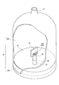
- the gas mist supply device 31 includes a storage section 32 (gas mist storage section 32A, liquid storage section 32B), a nozzle 33 that discharges the gas supplied from the gas supply means 11 from the tip opening, and a liquid stored in the liquid storage section 32B.
- a gas supply port for introducing gas from the gas supply unit 11 into the gas mist storage unit 32A and a liquid supply port for introducing liquid from the liquid supply unit 21 into the liquid storage unit 32B are provided. Each is provided.
- the storage part 32 is divided into a gas mist storage part 32A and a liquid storage part 32B by a shielding plate 34 as shown in FIG.
- the upper side (nozzle tip opening 33A side) of the shielding plate 34 is a gas mist storage part 32A that stores the generated gas mist
- the lower side (storage part 32 bottom side) is a liquid storage part 32B that stores liquid.
- a nozzle 33 is provided at the center of the bottom side of the reservoir 32.
- the nozzle 33 is formed in a substantially conical cylinder shape from the bottom side of the storage portion 32 toward the top. Its proximal end is connected to the gas supply means 11 on the outer surface of the apparatus, its distal end protrudes toward the gas mist reservoir 32A, and gas can be discharged from the distal opening 33A.
- the proximal end of the nozzle 33 is connected to the gas supply means 11 directly or via a tube or the like, and it is desirable that the connecting portion is composed of a connector or the like that can be connected with one touch.
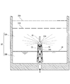
- the liquid absorption pipe 36 ⁇ / b> A is formed between the nozzle 33 and the liquid absorption pipe forming member 36 having a substantially conical cylindrical shape that is slightly larger than the nozzle 33. That is, as shown in FIG. 2, by arranging the nozzle 33 so as to cover the liquid absorbing tube forming member 36, the liquid absorbing tube is provided between the outer peripheral surface of the nozzle 33 and the inner peripheral surface of the liquid absorbing tube forming member 36. 36A is formed. Further, a gap is formed between the base end of the liquid suction pipe forming member 36 and the bottom surface of the liquid storage part 32B, and the liquid stored in the liquid storage part 32B is sucked up by the liquid suction pipe 36A. The tip end portion 36B of the liquid suction pipe forming member 36 is opened near the tip opening 33A of the nozzle 33 so that the liquid sucked up from the liquid suction pipe 36A hits the gas flow discharged from the nozzle 33. It is configured.
- the baffle 35 is a member disposed at a position facing the tip opening 33 ⁇ / b> A of the nozzle 33 and the tip portion 36 ⁇ / b> B of the liquid suction pipe forming member 36, and is connected to the liquid suction pipe forming member 36 here.
- the structure connected with the shielding board 34 or the storage part 32 may be sufficient.
- the liquid absorption pipe forming member 36 is connected to the shielding plate 34 at a substantially central portion in the vertical direction.
- the shielding plate 34 is also connected to the inside of the storage portion 32 at the outer periphery thereof.
- the gas mist supply device 31 is integrally formed as a whole.
- the shielding plate 34 has an action of pushing the liquid upward in the liquid absorption pipe forming member 36 by maintaining the pressure in the liquid storage part 32B higher than the pressure in the gas mist storage part 32A. For this reason, the shielding plate 34 may be fixed at a predetermined position on the inner wall of the liquid storage portion 32B, but may be configured to be movable up and down according to the liquid level in the liquid storage portion 32B. Further, the shielding plate 34 may not be provided depending on the magnitude of the gas pressure discharged from the tip opening 33A.
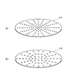
- one or a plurality of (for example, two in FIG. 5) plates 31 ⁇ / b> A and 31 ⁇ / b> B may be provided at a position above the nozzle 33 in the gas mist reservoir 32 ⁇ / b> A.
- FIG. 6 shows an example of the plates 31A and 31B.
- each of the plates 31A and 31B is provided with a plurality of pores, and the generated gas mist is refined by passing through the pores.
- the diameter of the pores of the upper plate 31A is smaller than the diameter of the pores of the lower plate 31B. It is.
- the gas from the gas supply means 11 is supplied to the nozzle 33 in a state where the liquid is stored in the liquid storage portion 32B.
- the gas is discharged at an increased flow rate.
- the liquid is sucked up by the negative pressure generated by the air flow at this time, and is sucked up by the gas flow near the tip opening 33A of the nozzle 33 and collides with the lower end of the baffle 35.
- the liquid is pulverized by this collision, and mixed with gas and dissolved to generate gas mist.
- the particle size of the mist generated at this time is desirably fine, and specifically, it is optimal to be 10 ⁇ m or less.
- the generated gas mist spreads in the gas mist reservoir 32A and is discharged from the gas mist outlet 37 according to the convection of the gas.
- the gas mist reservoir 32A preferably has a dome shape that is convex toward the top having a curved surface.
- the gas mist discharge port 37 is provided in the substantially dome-shaped top part.
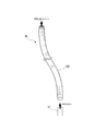
- the gas mist discharged from the gas mist discharge port 37 is supplied into the living body pressure bath cover 41 via the gas mist supply pipe 38.
- the gas mist supply pipe 38 is connected to the supply port 43 of the biological pressure bath cover 41.
- the gas mist supply pipe 38 is preferably provided with a droplet removal filter 39 for removing excess droplets adhering to the inside of the tube. Further, although not shown, a check valve for preventing the backflow of the gas mist and gas is provided inside the gas mist supply pipe 38.
- the gas mist supply pipe 38 is preferably composed of a flexible bellows-shaped pipe 38A, all or part of which is thick. If such a bellows-shaped tube 38A is used, it can be freely bent and expanded and contracted, so that the movement of the user is not restricted. Further, even if the gas mist flowing through the gas mist supply pipe 38 is gradually liquefied, the liquid can be removed from the uneven portion of the bellows.
- the liquid in the liquid storage unit 32B is supplied from the liquid supply unit 21.
- the liquid supply unit 21 may be omitted, and a liquid (chemical solution or the like) may be previously stored in the liquid storage unit 32B. good.
- a gas mist supply device 31 that is sealed in a state in which a liquid is contained in advance is prepared, and in use, this is connected to the gas supply means 11 and the biological pressure bath cover 41 to perform a gas mist pressure bath. After use, only the gas mist supply device 31 is removed and discarded. Thus, it becomes possible to perform a gas mist pressure bath hygienically and simply by setting it as a disposable structure.
- the living body pressure bath cover 41 is a cover that covers the skin and mucous membrane of a living body (here, as an example, a lower limb of a human body) and can form a space in which gas mist and gas are enclosed.
- the biological pressure bath cover 41 is made of a pressure-resistant, non-breathable, and non-breathable material.
- it is preferably made of natural rubber, silicon rubber, polyethylene, polypropylene, polyvinylidene chloride, polystyrene, polyvinyl acetate, polyvinyl chloride, polyamide resin, polytetrafluoroethylene, or the like.
- the supply port 43 for introducing gas mist and gas into the inside is provided.
- a check valve is provided inside the supply port 43 to prevent backflow of gas mist and gas.
- the living body pressure bath cover 41 may be provided with an opening or a valve that can discharge gas and gas mist in order to adjust the internal pressure. These pressure adjustments may be performed manually, but are preferably automatically performed by the control device 51 together with the supply control of gas and gas mist based on the measured value of the pressure gauge 61 described later.
- a safety valve (a relief valve) that automatically opens when the pressure inside the living body pressure bath cover 41 becomes equal to or higher than a certain pressure may be provided.
- a pressure gauge 61 for measuring the internal pressure is installed in the living body pressure bath cover 41.
- the control device 51 keeps the pressure value in the living body pressure bath cover 41 at 1 atmosphere or more (more preferably about 1.02 to 2.5 atmospheres).
- To control the supply For example, the supply of gas from the gas supply means 11 is adjusted or stopped, or the gas mist or gas is discharged from the biological pressure bath cover 41.
- a thermometer 62 for measuring the temperature in the biological pressure bath cover 41 is installed inside the biological pressure bath cover 41.
- the control device 51 turns on / off the heater provided in the liquid supply means 21 based on the measured value of the thermometer 62 in order to keep the living body pressure bath cover 41 at a set temperature (for example, about 38 ° C.) at which a warm bath effect is obtained. Etc.
- the opening portion of the living body pressure bath cover 41 is provided with a fastening portion 42 that enables attachment to and removal from a living body (here, the lower limb of a human body) and prevents leakage of gas mist and gas enclosed therein.
- the fastening part 42 is preferably composed of, for example, a stretchable surface fastener. Or you may use a string, rubber
- a material that adheres to the user's skin may be disposed on the inner side surface of the living body pressure bath cover 41 (such as the inner side surface of the fastening portion 42).
- the adhesive material is preferably a viscoelastic gel made of, for example, polyurethane or silicone rubber. Further, it is preferable that the adhesive material is detachable and can be replaced every time it is used or when the viscosity is low.
- the control device 51 includes a computer having a CPU, a memory, and a display. Then, the pressure adjustment of the gas supplied from the gas supply means 11, the switching of the supply location, the on / off switching, the liquid supply pressure adjustment and the temperature adjustment from the liquid supply means 21, the on / off switching of the supply, the supply of the gas mist Various controls such as on / off switching are performed so that the gas mist pressure bath can be performed in an optimum state. In particular, it is preferable that the control device 51 stops the gas supply of the gas supply means 11 when the pressure value in the living body pressure bath cover 41 becomes a predetermined value or more.
- the biological pressure bath cover 41 is fixed to the living body (here, the lower limb of the human body) and sealed.
- a predetermined amount of liquid is injected from the liquid supply means 21 into the liquid storage section 32B of the gas mist supply device 31, and then gas is supplied from the gas supply means 11 to the nozzle 33 to generate gas mist.
- the control device 51 adjusts the supply pressure, amount, temperature, and the like of the liquid and gas.
- the generated gas mist is supplied from the supply port 43 into the living body pressure bath cover 41.
- the gas is supplied directly to the gas mist reservoir 32A instead of the nozzle 33.
- the living body pressure bath cover 41 has a gas of about 95-97% and a liquid of about 3-5%.
- the gas is preferably dissolved in the mist at a concentration of about 40 ppm, and the bubble size is preferably about 232 pm.
- the control device 51 detects the gas mist when the pressure inside the living body pressure bath cover 41 is optimally pressurized and heated (about 1.02 to 2.5 atm, about 38 ° C.) from the measured values of the pressure gauge 61 and the thermometer 62. Alternatively, the gas supply is temporarily stopped and a gas mist pressure bath is performed in this state.
- the lower limb of the human body is described as an example of a living body part for performing a gas mist pressure bath.
- the present invention can be applied to various parts. In that case, an optimal gas mist pressure bath is performed using the living body pressure bath cover 41 having a shape matched to the target region.
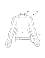
- FIGS. 7 to 9 show examples of various shapes of the body pressure bath cover 41.
- FIG. 7 shows an outline of a living body pressure bath cover 41A for the upper body of a human body.
- the living body pressure bath cover 41A has a shape that covers the entire upper body, and the waist opening is provided with a fastening portion 42A that can be attached / detached and prevents gas mist and gas leaking inside. ing.
- a fastening portion 44A is provided in the opening of the neck portion.
- 43A is a supply port for introducing gas mist and gas into the interior.
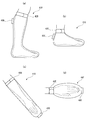
- FIG. 8 shows an example of the shape of the biological pressure bath cover 41 that covers a more local part of the living body.
- FIG. 8A shows a living body pressure bath cover 41B for one lower limb (lower knee) of a human body.
- the living body pressure bath cover 41B is provided with a fastening portion 42B at its opening and a supply port 43B for introducing gas mist and gas into the inside.
- FIG. 8B shows a living body pressure bath cover 41C for a foot part of a human body.
- the living body pressure bath cover 41C is provided with a fastening portion 42C at its opening and a supply port 43C for introducing gas mist and gas into the inside.
- FIG. 8C shows a biological pressure bath cover 41D for the forearm of the human body.
- the living body pressure bath cover 41D is provided with a fastening portion 42D at its opening and a supply port 43D for introducing gas mist and gas into the inside.
- FIG. 8D shows a biological pressure bath cover 41E for the human hand.
- the living body pressure bath cover 41E is provided with a fastening portion 42E at its opening and a supply port 43E for introducing gas mist and gas into the inside.
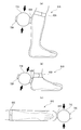
- FIG. 9 shows an example of a patch-like body pressure bath cover 41F.
- FIG. 9A is a diagram showing an outline of the patch-shaped biological pressure bath cover 41F
- FIG. 9B is a view when the patch-shaped biological pressure bath cover 41F is attached to a living body (here, a human lower limb). It is a figure which shows an external appearance.
- the living body pressure bath cover 41F includes a cover part 45F that covers the skin and mucous membrane of the living body, a fastening part 42F that is provided at the periphery of the cover part 45F and is directly attached to the skin and mucous membrane of the living body, and a cover part 45F.
- a supply port 43F for supplying gas mist and gas into the space formed by the fastening part 42F and a fixing part 44F made of a belt, a string or the like for fixing the cover part 45F to the living body are constituted.
- the living body pressure bath cover 41 may have various shapes other than the examples shown in FIGS. In short, any shape can be used as long as it can cover the skin and mucous membrane of a living body and form a space for enclosing gas mist and gas inside. Moreover, the exhaust port for discharging
- the control device 51 supplies gas mist intermittently into the living body pressure bath cover 41 at a constant rhythm. Also good. When the interval pressurization interval at that time is substantially synchronized with the pulsation of the pulse, the effect becomes high.
- FIG. 10 is an overall schematic view of a gas mist pressure bath system according to the second embodiment of the present invention.
- a gas mist pressure bath system further provided with pressurizing means for facilitating pressurization in the living body pressure bath cover will be described.
- symbol is attached
- a living body pressure bath cover 81 that forms a space for enclosing gas mist and gas therein, and the living body pressure bath cover 81 are connected to the living body pressure bath.
- a pressurizing unit (gas reservoir) 71 that pressurizes the inside of the cover 81 is provided.
- the biological pressure bath cover 81 has substantially the same structure as the biological pressure bath cover 41 shown in the first embodiment, and includes a fastening portion 82 and a gas mist and gas supply port 83. However, the gas mist supply port 83 is connected to the pressurizing unit 71 here. In addition, here, as an example, a living body pressure bath cover 81 having a shape covering the hand portion of the human body is illustrated.
- the pressurizing unit 71 is a hollow gas reservoir connected to the biological pressure bath cover 81 in order to pressurize the interior of the biological pressure bath cover 81.
- the pressurizing unit 71 is connected to the supply port 83 of the biological pressure bath cover 81 and has a supply port 72 itself, from which gas mist or gas is supplied to the inside.
- the supply port 72 of the pressurizing unit 71 is also provided with a check valve for preventing the backflow of gas mist and gas.
- the pressurizing unit 71 may be configured to be manually pressed, or may be mechanically performed under the control of the control device 51 using a drive device or the like. As described above, the pressurization in the gas mist pressure bath increases the effect by being pulsed at predetermined intervals. Therefore, the pressurizing unit 71 may be intermittently pressed at a constant rhythm. When the interval pressurization interval at that time is substantially synchronized with the pulsation of the pulse, the effect becomes high.
- the living body pressure bath cover 81 is fixed to the living body (here, the hand portion of the human body) and sealed.
- a predetermined amount of liquid is injected from the liquid supply means 21 into the liquid storage section 32B of the gas mist supply device 31, and then gas is supplied from the gas supply means 11 to the nozzle 33 to generate gas mist.
- the control device 51 adjusts the supply pressure, amount, temperature, and the like of the liquid and gas.
- the generated gas mist is supplied from the supply port 83 into the living body pressure bath cover 81 via the pressurizing unit 71.
- the gas is supplied directly to the gas mist reservoir 32A instead of the nozzle 33.
- gas is present in the living body pressure bath cover 81 at a ratio of about 95-97% and liquid at a ratio of about 3-5%.
- the gas is preferably dissolved in the mist at a concentration of about 40 ppm, and the bubble size is preferably about 232 pm.
- the control device 51 controls the internal pressure bath cover 81 from the measurement value of the thermometer 62 so as to reach an optimum temperature (for example, about 38 ° C.).
- the pressurizing unit 71 When the optimal amount of gas mist or gas is accumulated in the living body pressure bath cover 81 and the pressurizing unit 71, the pressurizing unit 71 is pressed so as to be crushed. As a result, the gas mist or gas in the pressurizing unit 71 is discharged into the living body pressure bath cover 81, and the inside of the living body pressure bath cover 81 is pressurized moderately (about 1.02 to 2.5 atm) to perform the gas mist pressure bath. .
- the living body pressure bath cover 81 can be used in various shapes in order to apply to various parts of the living body.
- the pressing part 71 is desirably a compact one that does not take up much space regardless of the pressing means, the biological pressure bath cover is also applied to a relatively compact one (covering a local part of the living body). It is suitable for.
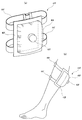
- FIG. 11 and FIG. 12 show examples of the shape of such a biological pressure bath cover 81 and the pressure unit 71 connected thereto.
- FIG. 11A shows a living body pressure bath cover 81A for one lower limb (lower knee) of a human body.
- the living body pressure bath cover 81 ⁇ / b> A is provided with a fastening portion 82 ⁇ / b> A at its opening and a supply port 83 ⁇ / b> B for introducing gas mist and gas into the inside.
- a pressure unit 71A is connected to the supply port 83A, and gas mist and gas are supplied into the biological pressure bath cover 81A via the supply port 72A of the pressure unit 71A.
- FIG. 11A shows a living body pressure bath cover 81A for one lower limb (lower knee) of a human body.
- the living body pressure bath cover 81 ⁇ / b> A is provided with a fastening portion 82 ⁇ / b> A at its opening and a supply port
- FIG. 11B shows a living body pressure bath cover 81B for a foot part of a human body.
- the living body pressure bath cover 81B is provided with a fastening portion 82B at its opening and a supply port 83B for introducing gas mist and gas into the inside.
- a pressurizing unit 71B is connected to the supply port 83B, and gas mist and gas are supplied into the living body pressure bath cover 81B via the supply port 72B of the pressurizing unit 71B.
- FIG. 11C shows a biological pressure bath cover 81C for the forearm of the human body.
- the living body pressure bath cover 81 ⁇ / b> C is provided with a fastening portion 82 ⁇ / b> C at its opening and a supply port 83 ⁇ / b> C for introducing gas mist and gas into the inside.
- a pressure unit 71C is connected to the supply port 83C, and gas mist and gas are supplied into the biological pressure bath cover 81C through the supply port 72C of the pressure unit 71C.
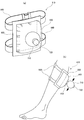
- FIG. 12 shows an example of a patch-shaped biological pressure bath cover 81D.
- FIG. 12A is a diagram showing an outline of the patch-shaped biological pressure bath cover 81D
- FIG. 12B is an external view when the patch-shaped biological pressure bath cover 81D is attached to a living body (here, a human lower limb).
- FIG. The living body pressure bath cover 81D includes a cover portion 85D that covers the skin and mucous membrane of the living body, a fastening portion 82D that is provided at the periphery of the cover portion 85D and is directly attached to the skin and mucous membrane of the living body, and a cover portion 85D.
- a pressurization unit 71D is connected to the supply port 83D, and gas mist and gas are supplied into the living body pressure bath cover 81D via the supply port 72D of the pressurization unit 71D.
- the living body pressure bath cover 81 may be provided with an exhaust port for discharging internal gas mist and gas and adjusting pressure. Moreover, it can be applied not only to the human body but also to living organisms such as animals.
- the pressurizing means 71 is a hollow gas reservoir connected to the biological pressure bath cover 81, but other members that compress the biological pressure bath cover 81 itself so as to be crushed from the outer periphery, etc. Any material can be used as long as it can easily pressurize the biological pressure bath cover 81.
- FIG. 13 is an overall schematic diagram of a gas mist pressure bath system according to a third embodiment of the present invention.
- a gas mist pressure bath system further provided with means for charging the generated mist will be described.
- symbol is attached
- an electrode 92 is disposed at the gas mist outlet 37 of the gas mist supply device 31.
- the electrode 92 is connected to the power supply device 91, and the control device 51 performs voltage value setting and on / off control.
- the electrode 92 gives an electric charge (a negative charge is desirable) when the mist generated by the gas mist supply device 31 is discharged from the gas mist discharge port 37.
- the mist can be charged and adhesion to a charged object can be improved.
- the adhesion to the skin and mucous membrane of the living body is improved, the effect of improving the gas absorption rate by the mist is further enhanced, and if the mist contains a drug as described above, the penetration into the skin and mucous membrane is promoted. can do.
- the biological pressure bath cover 41 is fixed to the living body (here, the lower limb of the human body) and sealed.
- a predetermined amount of liquid is injected from the liquid supply means 21 into the liquid storage section 32B of the gas mist supply device 31, and then gas is supplied from the gas supply means 11 to the nozzle 33 to generate gas mist.
- the control device 51 adjusts the supply pressure and amount of gas, the amount and temperature of liquid, and the like. Further, the control device 51 turns on the power supply device 91 and applies an electric charge from the electrode 92 to the mist.
- the generated gas mist is supplied from the supply port 43 into the living body pressure bath cover 41.
- the gas is supplied directly to the gas mist reservoir 32A instead of the nozzle 33.
- the living body pressure bath cover 41 has a gas of about 95-97% and a liquid of about 3-5%.
- the gas is preferably dissolved in the mist at a concentration of about 40 ppm, and the bubble size is preferably about 232 pm.
- the control device 51 detects the gas mist when the pressure inside the living body pressure bath cover 41 is optimally pressurized and heated (about 1.02 to 2.5 atm, about 38 ° C.) from the measured values of the pressure gauge 61 and the thermometer 62. Alternatively, the gas supply is temporarily stopped and a gas mist pressure bath is performed in this state.
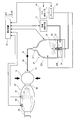
- FIG. 14 is an overall schematic diagram of a gas mist pressure bath system according to a fourth embodiment of the present invention.
- a gas mist pressure bath system further provided with liquid pressurizing means that pressurizes liquid from the liquid supply means and sends the liquid to the gas mist supply device will be described.
- symbol is attached
- a liquid pressurizing means 101 for pressurizing a liquid and sending it to the gas mist supply device 31 is arranged.
- the liquid pressurizing unit 101 is constituted by a pump or the like, pressurizes the liquid supplied from the liquid supply unit 21 and supplies the pressurized liquid to the liquid storage unit 32B of the gas mist supply device 31. By pressurizing the liquid in this way, the gas mist can be easily supplied by the gas mist supply device 31.
- the supply pressure adjustment in the liquid pressurizing means 101 is performed by the control device 51.
- the biological pressure bath cover 41 is fixed to the living body (here, the lower limb of the human body) and sealed.
- a predetermined amount of liquid is injected from the liquid supply means 21 through the liquid pressurization means 101 into the liquid storage section 32B of the gas mist supply device 31.
- gas mist is generated by supplying gas from the gas supply unit 11 to the liquid storage unit 32 ⁇ / b> B and the nozzle 33 while continuing to pressurize and supply the liquid from the liquid pressurization unit 101.
- the control device 51 adjusts the supply pressure, amount, temperature, and the like of the liquid and gas.
- the generated gas mist is supplied from the supply port 43 into the living body pressure bath cover 41.
- the gas is directly supplied to the gas mist reservoir 32A.
- the living body pressure bath cover 41 has a gas of about 95-97% and a liquid of about 3-5%.
- the gas is preferably dissolved in the mist at a concentration of about 40 ppm, and the bubble size is preferably about 232 pm.
- the control device 51 detects the gas mist when the pressure inside the living body pressure bath cover 41 is optimally pressurized and heated (about 1.02 to 2.5 atm, about 38 ° C.) from the measured values of the pressure gauge 61 and the thermometer 62. Alternatively, the gas supply is temporarily stopped and a gas mist pressure bath is performed in this state.
- the lower limb of the human body is described as an example of a living body part for performing a gas mist pressure bath.
- the present invention can be applied to various parts. In that case, an optimal gas mist pressure bath is performed using the living body pressure bath cover 41 having a shape matched to the target region.
- the amount of gas mist in the living body pressure bath cover, the pressure, etc. can be controlled by the control device, so that the gas mist pressure bath is always performed in an optimal state. Can do.
- the present invention relates to a gas mist pressure bath system that improves the absorption efficiency of gas from the skin and mucous membrane by directly contacting the gas mist obtained by pulverizing and dissolving gas and liquid with the skin and mucous membrane of a living body at a predetermined pressure value or more.
- a gas mist pressure bath system that improves the absorption efficiency of gas from the skin and mucous membrane by directly contacting the gas mist obtained by pulverizing and dissolving gas and liquid with the skin and mucous membrane of a living body at a predetermined pressure value or more.
Priority Applications (6)
| Application Number | Priority Date | Filing Date | Title |
|---|---|---|---|
| CN201080001687.0A CN102046135B (zh) | 2009-02-06 | 2010-02-03 | 气雾压浴系统 |
| BRPI1011360A BRPI1011360A2 (pt) | 2009-02-06 | 2010-02-03 | sistema de banho de névoa gasosa sob pressão |
| EP10738541A EP2332509A1 (en) | 2009-02-06 | 2010-02-03 | Gas mist pressure bath system |
| AU2010211679A AU2010211679B2 (en) | 2009-02-06 | 2010-02-03 | Gas mist pressure bath system |
| US12/736,731 US20110060257A1 (en) | 2009-02-06 | 2010-02-03 | Gas mist pressure bath system |
| JP2010549489A JP4922459B2 (ja) | 2009-02-06 | 2010-02-03 | ガスミスト圧浴システム |
Applications Claiming Priority (8)
| Application Number | Priority Date | Filing Date | Title |
|---|---|---|---|
| JP2009-026767 | 2009-02-06 | ||
| JP2009-026766 | 2009-02-06 | ||
| JP2009-026769 | 2009-02-06 | ||
| JP2009-026768 | 2009-02-06 | ||
| JP2009026766 | 2009-02-06 | ||
| JP2009026768 | 2009-02-06 | ||
| JP2009026767 | 2009-02-06 | ||
| JP2009026769 | 2009-02-06 |
Publications (1)
| Publication Number | Publication Date |
|---|---|
| WO2010090210A1 true WO2010090210A1 (ja) | 2010-08-12 |
Family
ID=42542103
Family Applications (1)
| Application Number | Title | Priority Date | Filing Date |
|---|---|---|---|
| PCT/JP2010/051492 WO2010090210A1 (ja) | 2009-02-06 | 2010-02-03 | ガスミスト圧浴システム |
Country Status (8)
| Country | Link |
|---|---|
| US (1) | US20110060257A1 (ko) |
| EP (1) | EP2332509A1 (ko) |
| JP (1) | JP4922459B2 (ko) |
| KR (1) | KR20110118124A (ko) |
| CN (1) | CN102046135B (ko) |
| AU (1) | AU2010211679B2 (ko) |
| BR (1) | BRPI1011360A2 (ko) |
| WO (1) | WO2010090210A1 (ko) |
Cited By (5)
| Publication number | Priority date | Publication date | Assignee | Title |
|---|---|---|---|---|
| WO2012099252A1 (ja) * | 2011-01-21 | 2012-07-26 | 日本エー・シー・ピー株式会社 | ガスミスト圧浴システム |
| EP2586417A1 (en) * | 2010-12-20 | 2013-05-01 | Shoichi Nakamura | Carbon dioxide gas mist pressure bath method and carbon dioxide gas mist pressure bath apparatus for preventing, improving and treating myocardial infarctions |
| EP2586418A1 (en) * | 2010-12-20 | 2013-05-01 | Shoichi Nakamura | Carbon dioxide gas mist pressure bath method and carbon dioxide gas mist pressure bath apparatus for improving and promoting circulation of blood in ischemic region of organism |
| WO2013065777A1 (ja) * | 2011-11-04 | 2013-05-10 | 日本エー・シー・ピー株式会社 | ガスミスト圧浴システム |
| EP2676653A1 (en) * | 2011-02-17 | 2013-12-25 | Shoichi Nakamura | Pressurized gas mist bathing system |
Families Citing this family (5)
| Publication number | Priority date | Publication date | Assignee | Title |
|---|---|---|---|---|
| EP2532341A1 (en) * | 2011-06-07 | 2012-12-12 | Burghardt Krebber | Kit of parts for the treatment of infectious disease |
| CA3085086C (en) | 2011-12-06 | 2023-08-08 | Delta Faucet Company | Ozone distribution in a faucet |
| CN103893905B (zh) * | 2014-04-02 | 2016-01-27 | 宁波江北怡和工业设计有限公司 | 背部敷药器 |
| CN103893906B (zh) * | 2014-04-02 | 2016-01-20 | 宁波江北怡和工业设计有限公司 | 一种背部敷药器 |
| WO2017112795A1 (en) | 2015-12-21 | 2017-06-29 | Delta Faucet Company | Fluid delivery system including a disinfectant device |
Citations (11)
| Publication number | Priority date | Publication date | Assignee | Title |
|---|---|---|---|---|
| JPS61217132A (ja) * | 1985-03-22 | 1986-09-26 | 松下電工株式会社 | 血圧計 |
| JPH07171189A (ja) | 1993-12-17 | 1995-07-11 | Matsushita Electric Works Ltd | 血行促進装置 |
| JPH1147533A (ja) * | 1997-08-07 | 1999-02-23 | Fine:Kk | 気体処理装置 |
| JP2005058745A (ja) * | 2003-07-28 | 2005-03-10 | Nextier:Kk | 二酸化炭素治療装置 |
| JP2005205163A (ja) * | 2003-06-30 | 2005-08-04 | Pijon:Kk | 理美容機用ミスト噴霧装置 |
| JP2006026022A (ja) * | 2004-07-14 | 2006-02-02 | Aglex Inc | 理美容用蒸気発生装置 |
| JP2007014482A (ja) * | 2005-07-06 | 2007-01-25 | Hitachi Ltd | 人工炭酸泉製造装置 |
| JP3144718U (ja) * | 2008-06-27 | 2008-09-11 | 正一 中村 | 炭酸ガス浴用カバー |
| JP3144717U (ja) * | 2008-06-27 | 2008-09-11 | 正一 中村 | 炭酸ガス浴用カバー |
| JP3150690U (ja) * | 2009-03-10 | 2009-05-28 | 中村 正一 | ガスミスト圧浴用カバー |
| JP3150692U (ja) * | 2009-03-10 | 2009-05-28 | 中村 正一 | ガスミスト圧浴用カバー |
Family Cites Families (14)
| Publication number | Priority date | Publication date | Assignee | Title |
|---|---|---|---|---|
| US3826255A (en) * | 1972-06-22 | 1974-07-30 | Hudson Oxygen Therapy Sales Co | Intermittent positive pressure breathing manifold |
| US4792097A (en) * | 1987-03-31 | 1988-12-20 | Mallinckrodt, Inc. | Non-sputtering nebulizer |
| US4772259A (en) * | 1987-06-12 | 1988-09-20 | Ballard Medical Products | Hyperbaric oxygenation apparatus and methods |
| US5054478A (en) * | 1989-04-21 | 1991-10-08 | Trudell Medical | Nebulizer |
| JP2979416B2 (ja) * | 1989-10-30 | 1999-11-15 | カシオ計算機株式会社 | キー入力装置 |
| US5823179A (en) * | 1996-02-13 | 1998-10-20 | 1263152 Ontario Inc. | Nebulizer apparatus and method |
| WO2003009788A1 (de) * | 2001-07-25 | 2003-02-06 | Zimmer Elektromedizin Gmbh | Thermischer applikator und applikatorsystem |
| TW580384B (en) * | 2002-07-01 | 2004-03-21 | Neochemir Inc | Carbon dioxide administrating device |
| JP2006062024A (ja) * | 2004-08-26 | 2006-03-09 | Ebara Corp | ミスト生成装置 |
| JP2006322683A (ja) * | 2005-05-20 | 2006-11-30 | Mitsubishi Heavy Ind Ltd | 蒸気発生器 |
| WO2007100857A2 (en) * | 2006-02-28 | 2007-09-07 | Vortexx Group, Inc. | Nozzle that produce angular momentum and methods for making and using same |
| RU2468785C2 (ru) * | 2006-10-18 | 2012-12-10 | Неокемир Инк. | Устройство для наружного введения диоксида углерода |
| JP2009018136A (ja) * | 2007-06-12 | 2009-01-29 | Tatsuo Okazaki | 炭酸温水による美容方法および機器 |
| JP4993638B2 (ja) * | 2008-06-27 | 2012-08-08 | 正一 中村 | ガスミスト圧浴装置 |
-
2010
- 2010-02-03 CN CN201080001687.0A patent/CN102046135B/zh not_active Expired - Fee Related
- 2010-02-03 AU AU2010211679A patent/AU2010211679B2/en not_active Ceased
- 2010-02-03 JP JP2010549489A patent/JP4922459B2/ja not_active Expired - Fee Related
- 2010-02-03 WO PCT/JP2010/051492 patent/WO2010090210A1/ja active Application Filing
- 2010-02-03 KR KR1020117012009A patent/KR20110118124A/ko not_active Application Discontinuation
- 2010-02-03 EP EP10738541A patent/EP2332509A1/en not_active Withdrawn
- 2010-02-03 BR BRPI1011360A patent/BRPI1011360A2/pt not_active IP Right Cessation
- 2010-02-03 US US12/736,731 patent/US20110060257A1/en not_active Abandoned
Patent Citations (11)
| Publication number | Priority date | Publication date | Assignee | Title |
|---|---|---|---|---|
| JPS61217132A (ja) * | 1985-03-22 | 1986-09-26 | 松下電工株式会社 | 血圧計 |
| JPH07171189A (ja) | 1993-12-17 | 1995-07-11 | Matsushita Electric Works Ltd | 血行促進装置 |
| JPH1147533A (ja) * | 1997-08-07 | 1999-02-23 | Fine:Kk | 気体処理装置 |
| JP2005205163A (ja) * | 2003-06-30 | 2005-08-04 | Pijon:Kk | 理美容機用ミスト噴霧装置 |
| JP2005058745A (ja) * | 2003-07-28 | 2005-03-10 | Nextier:Kk | 二酸化炭素治療装置 |
| JP2006026022A (ja) * | 2004-07-14 | 2006-02-02 | Aglex Inc | 理美容用蒸気発生装置 |
| JP2007014482A (ja) * | 2005-07-06 | 2007-01-25 | Hitachi Ltd | 人工炭酸泉製造装置 |
| JP3144718U (ja) * | 2008-06-27 | 2008-09-11 | 正一 中村 | 炭酸ガス浴用カバー |
| JP3144717U (ja) * | 2008-06-27 | 2008-09-11 | 正一 中村 | 炭酸ガス浴用カバー |
| JP3150690U (ja) * | 2009-03-10 | 2009-05-28 | 中村 正一 | ガスミスト圧浴用カバー |
| JP3150692U (ja) * | 2009-03-10 | 2009-05-28 | 中村 正一 | ガスミスト圧浴用カバー |
Cited By (13)
| Publication number | Priority date | Publication date | Assignee | Title |
|---|---|---|---|---|
| EP2586418A4 (en) * | 2010-12-20 | 2014-04-02 | Shoichi Nakamura | CARBON DIOXIDE GAS PRESSURE STEAM METHOD AND CARBON DIOXIDE GAS PRESSURE STEAM BATH APPARATUS FOR ENHANCING AND PROMOTING BLOOD CIRCULATION IN AN ISCHEMIC REGION OF THE ORGANISM |
| EP2586417A1 (en) * | 2010-12-20 | 2013-05-01 | Shoichi Nakamura | Carbon dioxide gas mist pressure bath method and carbon dioxide gas mist pressure bath apparatus for preventing, improving and treating myocardial infarctions |
| EP2586418A1 (en) * | 2010-12-20 | 2013-05-01 | Shoichi Nakamura | Carbon dioxide gas mist pressure bath method and carbon dioxide gas mist pressure bath apparatus for improving and promoting circulation of blood in ischemic region of organism |
| EP2586417A4 (en) * | 2010-12-20 | 2014-03-12 | Shoichi Nakamura | CARBON DIOXIDE GAS NOSE PRESSURE BATHING METHOD AND CARBON DIOXIDE GAS NOSE PRESSURE PRESSURE DEVICE FOR PREVENTING, TREATING AND TREATING MYOKARD INFARTS |
| JP2012148022A (ja) * | 2011-01-21 | 2012-08-09 | Shoichi Nakamura | ガスミスト圧浴システム |
| CN103140204A (zh) * | 2011-01-21 | 2013-06-05 | 中村正一 | 加压气雾洗浴系统 |
| WO2012099252A1 (ja) * | 2011-01-21 | 2012-07-26 | 日本エー・シー・ピー株式会社 | ガスミスト圧浴システム |
| US9278204B2 (en) | 2011-01-21 | 2016-03-08 | Acp Japan Co., Ltd. | Pressurized gas mist bathing system |
| EP2676653A1 (en) * | 2011-02-17 | 2013-12-25 | Shoichi Nakamura | Pressurized gas mist bathing system |
| EP2676653A4 (en) * | 2011-02-17 | 2014-10-22 | Shoichi Nakamura | PRESSURE GAS MIST BATH SYSTEM |
| WO2013065777A1 (ja) * | 2011-11-04 | 2013-05-10 | 日本エー・シー・ピー株式会社 | ガスミスト圧浴システム |
| CN103533917A (zh) * | 2011-11-04 | 2014-01-22 | 中村正一 | 气雾压浴系统 |
| JPWO2013065777A1 (ja) * | 2011-11-04 | 2015-04-02 | 中村 正一 | ガスミスト圧浴システム |
Also Published As
| Publication number | Publication date |
|---|---|
| JP4922459B2 (ja) | 2012-04-25 |
| KR20110118124A (ko) | 2011-10-28 |
| CN102046135B (zh) | 2014-02-19 |
| BRPI1011360A2 (pt) | 2016-03-15 |
| CN102046135A (zh) | 2011-05-04 |
| US20110060257A1 (en) | 2011-03-10 |
| AU2010211679B2 (en) | 2014-01-16 |
| AU2010211679A1 (en) | 2010-08-12 |
| JPWO2010090210A1 (ja) | 2012-08-09 |
| EP2332509A1 (en) | 2011-06-15 |
Similar Documents
| Publication | Publication Date | Title |
|---|---|---|
| JP4922459B2 (ja) | ガスミスト圧浴システム | |
| JP5088905B2 (ja) | ガスミスト圧浴システム | |
| JP5406214B2 (ja) | 炭酸ガスミスト圧浴システム | |
| JP5474042B2 (ja) | ガスミスト圧浴システム | |
| JP5088906B2 (ja) | 炭酸ガスミスト圧浴システム | |
| JP5995373B2 (ja) | ガスミスト圧浴システム | |
| JP5553416B2 (ja) | ガスミスト圧浴システム | |
| JP5517260B2 (ja) | ガスミスト圧浴システム | |
| JP5102377B2 (ja) | ガスミスト圧浴システム | |
| JP5305550B2 (ja) | ガスミスト圧浴システム | |
| JP5473942B2 (ja) | ガスミスト圧浴システム | |
| JP5517261B2 (ja) | ガスミスト圧浴システム | |
| WO2010074198A1 (ja) | ガスミスト圧浴用カバー | |
| JP5743587B2 (ja) | ガスミスト圧浴システム |
Legal Events
| Date | Code | Title | Description |
|---|---|---|---|
| WWE | Wipo information: entry into national phase |
Ref document number: 201080001687.0 Country of ref document: CN |
|
| 121 | Ep: the epo has been informed by wipo that ep was designated in this application |
Ref document number: 10738541 Country of ref document: EP Kind code of ref document: A1 |
|
| WWE | Wipo information: entry into national phase |
Ref document number: 2010549489 Country of ref document: JP Ref document number: 12736731 Country of ref document: US |
|
| WWE | Wipo information: entry into national phase |
Ref document number: 7936/DELNP/2010 Country of ref document: IN |
|
| WWE | Wipo information: entry into national phase |
Ref document number: 2010738541 Country of ref document: EP |
|
| WWE | Wipo information: entry into national phase |
Ref document number: 2010211679 Country of ref document: AU |
|
| ENP | Entry into the national phase |
Ref document number: 2010211679 Country of ref document: AU Date of ref document: 20100203 Kind code of ref document: A |
|
| ENP | Entry into the national phase |
Ref document number: 20117012009 Country of ref document: KR Kind code of ref document: A |
|
| NENP | Non-entry into the national phase |
Ref country code: DE |
|
| REG | Reference to national code |
Ref country code: BR Ref legal event code: B01A Ref document number: PI1011360 Country of ref document: BR |
|
| ENP | Entry into the national phase |
Ref document number: PI1011360 Country of ref document: BR Kind code of ref document: A2 Effective date: 20110805 |