WO2010090206A1 - 導電性高分子組成物及びその製造方法、並びに導電性高分子組成物を用いた固体電解コンデンサ - Google Patents
導電性高分子組成物及びその製造方法、並びに導電性高分子組成物を用いた固体電解コンデンサ Download PDFInfo
- Publication number
- WO2010090206A1 WO2010090206A1 PCT/JP2010/051486 JP2010051486W WO2010090206A1 WO 2010090206 A1 WO2010090206 A1 WO 2010090206A1 JP 2010051486 W JP2010051486 W JP 2010051486W WO 2010090206 A1 WO2010090206 A1 WO 2010090206A1
- Authority
- WO
- WIPO (PCT)
- Prior art keywords
- conductive polymer
- polymer composition
- electrolytic capacitor
- layer
- solid electrolytic
- Prior art date
Links
Images

Classifications
-
- H—ELECTRICITY
- H01—ELECTRIC ELEMENTS
- H01B—CABLES; CONDUCTORS; INSULATORS; SELECTION OF MATERIALS FOR THEIR CONDUCTIVE, INSULATING OR DIELECTRIC PROPERTIES
- H01B1/00—Conductors or conductive bodies characterised by the conductive materials; Selection of materials as conductors
- H01B1/06—Conductors or conductive bodies characterised by the conductive materials; Selection of materials as conductors mainly consisting of other non-metallic substances
- H01B1/12—Conductors or conductive bodies characterised by the conductive materials; Selection of materials as conductors mainly consisting of other non-metallic substances organic substances
- H01B1/124—Intrinsically conductive polymers
- H01B1/127—Intrinsically conductive polymers comprising five-membered aromatic rings in the main chain, e.g. polypyrroles, polythiophenes
-
- C—CHEMISTRY; METALLURGY
- C08—ORGANIC MACROMOLECULAR COMPOUNDS; THEIR PREPARATION OR CHEMICAL WORKING-UP; COMPOSITIONS BASED THEREON
- C08L—COMPOSITIONS OF MACROMOLECULAR COMPOUNDS
- C08L65/00—Compositions of macromolecular compounds obtained by reactions forming a carbon-to-carbon link in the main chain; Compositions of derivatives of such polymers
-
- C—CHEMISTRY; METALLURGY
- C09—DYES; PAINTS; POLISHES; NATURAL RESINS; ADHESIVES; COMPOSITIONS NOT OTHERWISE PROVIDED FOR; APPLICATIONS OF MATERIALS NOT OTHERWISE PROVIDED FOR
- C09D—COATING COMPOSITIONS, e.g. PAINTS, VARNISHES OR LACQUERS; FILLING PASTES; CHEMICAL PAINT OR INK REMOVERS; INKS; CORRECTING FLUIDS; WOODSTAINS; PASTES OR SOLIDS FOR COLOURING OR PRINTING; USE OF MATERIALS THEREFOR
- C09D125/00—Coating compositions based on homopolymers or copolymers of compounds having one or more unsaturated aliphatic radicals, each having only one carbon-to-carbon double bond, and at least one being terminated by an aromatic carbocyclic ring; Coating compositions based on derivatives of such polymers
- C09D125/18—Homopolymers or copolymers of aromatic monomers containing elements other than carbon and hydrogen
-
- H—ELECTRICITY
- H01—ELECTRIC ELEMENTS
- H01G—CAPACITORS; CAPACITORS, RECTIFIERS, DETECTORS, SWITCHING DEVICES OR LIGHT-SENSITIVE DEVICES, OF THE ELECTROLYTIC TYPE
- H01G11/00—Hybrid capacitors, i.e. capacitors having different positive and negative electrodes; Electric double-layer [EDL] capacitors; Processes for the manufacture thereof or of parts thereof
- H01G11/22—Electrodes
- H01G11/30—Electrodes characterised by their material
- H01G11/48—Conductive polymers
-
- H—ELECTRICITY
- H01—ELECTRIC ELEMENTS
- H01G—CAPACITORS; CAPACITORS, RECTIFIERS, DETECTORS, SWITCHING DEVICES OR LIGHT-SENSITIVE DEVICES, OF THE ELECTROLYTIC TYPE
- H01G11/00—Hybrid capacitors, i.e. capacitors having different positive and negative electrodes; Electric double-layer [EDL] capacitors; Processes for the manufacture thereof or of parts thereof
- H01G11/54—Electrolytes
- H01G11/56—Solid electrolytes, e.g. gels; Additives therein
-
- H—ELECTRICITY
- H01—ELECTRIC ELEMENTS
- H01G—CAPACITORS; CAPACITORS, RECTIFIERS, DETECTORS, SWITCHING DEVICES OR LIGHT-SENSITIVE DEVICES, OF THE ELECTROLYTIC TYPE
- H01G9/00—Electrolytic capacitors, rectifiers, detectors, switching devices, light-sensitive or temperature-sensitive devices; Processes of their manufacture
- H01G9/0029—Processes of manufacture
- H01G9/0036—Formation of the solid electrolyte layer
-
- H—ELECTRICITY
- H01—ELECTRIC ELEMENTS
- H01G—CAPACITORS; CAPACITORS, RECTIFIERS, DETECTORS, SWITCHING DEVICES OR LIGHT-SENSITIVE DEVICES, OF THE ELECTROLYTIC TYPE
- H01G9/00—Electrolytic capacitors, rectifiers, detectors, switching devices, light-sensitive or temperature-sensitive devices; Processes of their manufacture
- H01G9/004—Details
- H01G9/022—Electrolytes; Absorbents
- H01G9/025—Solid electrolytes
- H01G9/028—Organic semiconducting electrolytes, e.g. TCNQ
-
- H—ELECTRICITY
- H01—ELECTRIC ELEMENTS
- H01G—CAPACITORS; CAPACITORS, RECTIFIERS, DETECTORS, SWITCHING DEVICES OR LIGHT-SENSITIVE DEVICES, OF THE ELECTROLYTIC TYPE
- H01G9/00—Electrolytic capacitors, rectifiers, detectors, switching devices, light-sensitive or temperature-sensitive devices; Processes of their manufacture
- H01G9/15—Solid electrolytic capacitors
-
- C—CHEMISTRY; METALLURGY
- C08—ORGANIC MACROMOLECULAR COMPOUNDS; THEIR PREPARATION OR CHEMICAL WORKING-UP; COMPOSITIONS BASED THEREON
- C08G—MACROMOLECULAR COMPOUNDS OBTAINED OTHERWISE THAN BY REACTIONS ONLY INVOLVING UNSATURATED CARBON-TO-CARBON BONDS
- C08G2261/00—Macromolecular compounds obtained by reactions forming a carbon-to-carbon link in the main chain of the macromolecule
- C08G2261/30—Monomer units or repeat units incorporating structural elements in the main chain
- C08G2261/32—Monomer units or repeat units incorporating structural elements in the main chain incorporating heteroaromatic structural elements in the main chain
- C08G2261/322—Monomer units or repeat units incorporating structural elements in the main chain incorporating heteroaromatic structural elements in the main chain non-condensed
- C08G2261/3221—Monomer units or repeat units incorporating structural elements in the main chain incorporating heteroaromatic structural elements in the main chain non-condensed containing one or more nitrogen atoms as the only heteroatom, e.g. pyrrole, pyridine or triazole
-
- C—CHEMISTRY; METALLURGY
- C08—ORGANIC MACROMOLECULAR COMPOUNDS; THEIR PREPARATION OR CHEMICAL WORKING-UP; COMPOSITIONS BASED THEREON
- C08G—MACROMOLECULAR COMPOUNDS OBTAINED OTHERWISE THAN BY REACTIONS ONLY INVOLVING UNSATURATED CARBON-TO-CARBON BONDS
- C08G2261/00—Macromolecular compounds obtained by reactions forming a carbon-to-carbon link in the main chain of the macromolecule
- C08G2261/30—Monomer units or repeat units incorporating structural elements in the main chain
- C08G2261/32—Monomer units or repeat units incorporating structural elements in the main chain incorporating heteroaromatic structural elements in the main chain
- C08G2261/322—Monomer units or repeat units incorporating structural elements in the main chain incorporating heteroaromatic structural elements in the main chain non-condensed
- C08G2261/3223—Monomer units or repeat units incorporating structural elements in the main chain incorporating heteroaromatic structural elements in the main chain non-condensed containing one or more sulfur atoms as the only heteroatom, e.g. thiophene
-
- C—CHEMISTRY; METALLURGY
- C08—ORGANIC MACROMOLECULAR COMPOUNDS; THEIR PREPARATION OR CHEMICAL WORKING-UP; COMPOSITIONS BASED THEREON
- C08G—MACROMOLECULAR COMPOUNDS OBTAINED OTHERWISE THAN BY REACTIONS ONLY INVOLVING UNSATURATED CARBON-TO-CARBON BONDS
- C08G2261/00—Macromolecular compounds obtained by reactions forming a carbon-to-carbon link in the main chain of the macromolecule
- C08G2261/70—Post-treatment
- C08G2261/76—Post-treatment crosslinking
-
- C—CHEMISTRY; METALLURGY
- C08—ORGANIC MACROMOLECULAR COMPOUNDS; THEIR PREPARATION OR CHEMICAL WORKING-UP; COMPOSITIONS BASED THEREON
- C08G—MACROMOLECULAR COMPOUNDS OBTAINED OTHERWISE THAN BY REACTIONS ONLY INVOLVING UNSATURATED CARBON-TO-CARBON BONDS
- C08G2261/00—Macromolecular compounds obtained by reactions forming a carbon-to-carbon link in the main chain of the macromolecule
- C08G2261/70—Post-treatment
- C08G2261/79—Post-treatment doping
- C08G2261/792—Post-treatment doping with low-molecular weight dopants
-
- C—CHEMISTRY; METALLURGY
- C08—ORGANIC MACROMOLECULAR COMPOUNDS; THEIR PREPARATION OR CHEMICAL WORKING-UP; COMPOSITIONS BASED THEREON
- C08L—COMPOSITIONS OF MACROMOLECULAR COMPOUNDS
- C08L25/00—Compositions of, homopolymers or copolymers of compounds having one or more unsaturated aliphatic radicals, each having only one carbon-to-carbon double bond, and at least one being terminated by an aromatic carbocyclic ring; Compositions of derivatives of such polymers
- C08L25/18—Homopolymers or copolymers of aromatic monomers containing elements other than carbon and hydrogen
-
- Y—GENERAL TAGGING OF NEW TECHNOLOGICAL DEVELOPMENTS; GENERAL TAGGING OF CROSS-SECTIONAL TECHNOLOGIES SPANNING OVER SEVERAL SECTIONS OF THE IPC; TECHNICAL SUBJECTS COVERED BY FORMER USPC CROSS-REFERENCE ART COLLECTIONS [XRACs] AND DIGESTS
- Y02—TECHNOLOGIES OR APPLICATIONS FOR MITIGATION OR ADAPTATION AGAINST CLIMATE CHANGE
- Y02E—REDUCTION OF GREENHOUSE GAS [GHG] EMISSIONS, RELATED TO ENERGY GENERATION, TRANSMISSION OR DISTRIBUTION
- Y02E60/00—Enabling technologies; Technologies with a potential or indirect contribution to GHG emissions mitigation
- Y02E60/13—Energy storage using capacitors
Definitions
- the present embodiment relates to a conductive polymer composition, a method for producing the same, and a solid electrolytic capacitor using the conductive polymer composition.
- Conductive polymer materials are used for capacitor electrodes, dye-sensitized solar cell electrodes, electroluminescent display electrodes, and the like.
- conductive polymer materials polymer materials obtained by increasing the molecular weight such as pyrrole, thiophene, 3,4-ethylenedioxythiophene, and aniline are known.
- a conductive polymer material formed using a conductive polymer suspension solution having a poly anion as a dopant disclosed in Patent Documents 1 and 2 exhibits high conductivity. And has great interest.
- Patent Document 1 relates to a solution (dispersion) of polythiophene, a production method thereof, and use of a salt for antistatic treatment of a plastic molded body.
- Patent Document 2 discloses an aqueous dispersion of a complex of poly (3,4-dialkoxythiophene) and a polyanion, a method for producing the same, a coating composition containing the aqueous dispersion, and a composition to which the composition is applied.
- the present invention relates to a coated substrate having a transparent conductive film.
- Patent Documents 1 and 2 both describe a solution of polythiophene comprising a structural unit of 3,4-dialkoxythiophene and a polythiophene comprising polysulfonic acid ions derived from polystyrenesulfonic acid, a method for producing the same, and antistatic of a plastic molded article Relates to the use of salt for processing.
- the method for forming a conductive polymer composition using the conductive polymer suspension solution as described above has an advantage that a conductive polymer composition with high conductivity can be obtained simply by drying the solution. Therefore, in place of conventional methods for forming conductive polymers by chemical oxidative polymerization or electrolytic polymerization, application to solid electrolytic capacitors using a conductive polymer composition as a solid electrolyte is progressing.
- a conductive polymer composition is used as the solid electrolyte of the solid electrolytic capacitor, as described in Patent Document 3, in order to suppress leakage current (hereinafter referred to as LC) when mounted on the substrate,
- LC leakage current
- Patent Document 3 relates to a method of forming a polypyrrole layer having a thickness of 5 ⁇ m or more using a chemical oxidation polymerization method as a solid electrolyte of a solid electrolytic capacitor.
- the thermal stress of the exterior resin is applied to the oxide film, the oxide film may be damaged, and the LC may become large, but if a conductive polymer layer is formed on the oxide film, Due to the increase in LC, the oxide film locally generates heat, and the conductive polymer layer formed thereon is thermally oxidized and eventually loses its conductivity. As a result, the current is interrupted to the defective portion of the oxide film, so that even if LC temporarily increases, it eventually returns to the normal level.
- the cause of the increase in LC in board mounting is not clear, but one reason is that the conductive polymer layer is displaced due to thermal stress during board mounting, and in a microscopic region. It is considered that a portion where the conductive polymer layer is not formed on the oxide film is generated, and the LC is increased for the reason described above.
- the above-described problems relating to the LC of the electrolytic capacitor are not limited to the conductive polymer obtained by chemical oxidative polymerization, but also apply to the conductive polymer obtained by drying the conductive polymer suspension.
- a valve action metal powder sintered body with an oxide film or etching treatment is used as a simple method for forming a conductive polymer composition obtained by drying a conductive polymer suspension on an oxide film of an electrolytic capacitor.
- the valve-acting metal body that has been subjected to is immersed in a conductive polymer suspension solution and then dried to form.
- the conductive polymer suspension solution does not have a certain viscosity
- the conductive polymer suspension in the valve action metal powder sintered body formed with an oxide film or the valve action metal body subjected to etching treatment is used. Since the adhesion amount of the solution is reduced, there is a problem that the amount of the conductive polymer formed is small and the thickness of the conductive polymer layer is reduced. In particular, the conductive polymer layer formed on the edge portion is formed thin.
- Patent Document 4 relates to a conductive composition containing a water-soluble conductive polymer having a sulfonic acid group and / or a carboxyl group, a crosslinking agent, water, an organic solvent, and a thickener.
- the thickener described in Patent Document 4 is an insulating water-soluble polymer, and when such an insulating component is present in the conductive polymer composition, the conductive polymer composition has a conductive property. There is a problem that the performance is impaired.
- the ESR of the solid electrolytic capacitor is similarly increased. .
- An object of the present embodiment is to provide a highly conductive conductive polymer composition that can provide a thick film with a small number of adhesions and a method for producing the same, and to provide a solid electrolytic capacitor that has low ESR and low LC.
- This embodiment has the following configuration to solve the above problems.
- the conductive polymer composition according to the present embodiment is formed by drying a conductive polymer suspension containing a polyanion having a crosslinked structure, a conductive polymer, and a solvent.
- the polyanion main chain having the cross-linked structure is polystyrene sulfonic acid.
- the poly anion having the crosslinked structure has a structure in which a polystyrene sulfonic acid having a linear structure is crosslinked using a crosslinking agent.
- the crosslinking agent is a compound having two or more epoxy groups.
- the conductive polymer is a polymer obtained by polymerizing at least one monomer selected from pyrrole, thiophene, furan and derivatives thereof.
- the viscosity of the conductive polymer suspension is 10 to 1000 mPa ⁇ s.
- the method for producing a conductive polymer composition is as follows: A first step in which a crosslinking agent and a polyanion are reacted in an aqueous solvent to synthesize a polyanion having a crosslinked structure; A second step in which a monomer containing a conductive polymer is chemically oxidatively polymerized using an oxidizing agent in a solvent containing a dopant consisting of an organic acid or a salt thereof to obtain a mixture containing the conductive polymer; A third step of recovering the conductive polymer from the mixture; A fourth step of mixing the polyanion having the crosslinked structure, the conductive polymer, and an oxidizing agent in the aqueous solvent to form a conductive polymer suspension; And a fifth step of drying the conductive polymer suspension.
- the dopant is at least one monosulfonic acid selected from benzenesulfonic acid, naphthalenesulfonic acid, camphorsulfonic acid and derivatives thereof, and salts thereof.
- the monomer is at least one selected from pyrrole, thiophene, furan and derivatives thereof.
- the solid electrolytic capacitor according to this embodiment is characterized in that the conductive polymer composition is used for a conductive polymer layer that is a solid electrolyte layer. Further, the conductive polymer composition is formed to have a thickness of 5 ⁇ m or more as the conductive polymer layer that is the solid electrolyte layer on the dielectric film layer formed on the surface of the anode conductor made of a valve metal. It is characterized by forming.
- the polyanion having a crosslinked structure is contained in the conductive polymer suspension solution, whereby the conductive polymer suspension solution is thickened. Then, by using the conductive polymer suspension solution, a thick film conductive polymer having a certain thickness or more in a single immersion and drying step in the conductive polymer suspension solution. A layer can be formed. Therefore, when applied to a solid electrolytic capacitor, a solid electrolytic capacitor having low ESR and low LC can be obtained.
- poly anions having a crosslinked structure are dopants for conductive polymers, they are completely different from general insulating thickeners in conductive polymer compositions obtained from conductive polymer suspensions. Even if it exists, it does not lower the conductivity. Therefore, the obtained conductive polymer composition exhibits high conductivity, and a low ESR solid electrolytic capacitor can be obtained by using the conductive polymer composition for a conductive polymer layer that is a solid electrolyte layer.
- Table 1 shows a comparison between the related art 1 described in Patent Document 1, the related art 2 described in Patent Document 4, and the present embodiment.
- the composition of the conductive polymer suspension solution is different from that of the prior art, and the conductive polymer composition obtained is different. According to the present embodiment, it is possible to provide a solid electrolytic capacitor having a low ESR and a low LC using the conductive polymer composition for the solid electrolyte layer.
- a conductive polymer composition formed using the conductive polymer suspension solution according to the present embodiment, a manufacturing method thereof, and a conductive polymer layer that is a solid electrolyte layer of the conductive polymer composition will be described in detail.
- the main chain of the polyanion having a crosslinked structure contained in the conductive polymer suspension solution according to the present embodiment is preferably a polyacid such as polystyrene sulfonic acid, polyvinyl sulfonic acid, polymaleic acid, polyacrylic acid, and the like.
- the polyanion main chain having a crosslinked structure is particularly preferably polystyrenesulfonic acid.
- the poly anion having a crosslinked structure preferably has a structure in which a poly anion having a linear structure is crosslinked using a crosslinking agent.
- the crosslinking agent that crosslinks the polyanion main chains is not particularly limited as long as it has two or more functional groups that react with the polyanion functional groups.
- an epoxy group, an isocyanate group, a carboxyl group It is preferable to have two or more functional groups such as amino group, hydroxyl group and mercapto group.
- a crosslinking agent having two or more epoxy groups is particularly preferable because it has good reactivity with the sulfone group contained in polystyrene sulfonic acid.
- Compounds having two or more epoxy groups include sorbitol polyglycidyl ether, polyglycerol polyglycidyl ether, pentaerythritol polyglycidyl ether, diglycerol polyglycidyl ether, glycerol polyglycidyl ether, trimethylolpropane polyglycidyl ether, resorcinol diglycidyl Ether, neopentyl glycol diglycidyl ether, 1,6-hexanediol diglycidyl ether, polyethylene glycol diglycidyl ether, polypropylene glycol diglycidyl ether, polybutadiene diglycidyl ether, diglycidyl-o-phthalate, hydroquinone diglycidyl ether, diglycidyl terephthalate Dibromoneopentyl glycol diglycy Ether, bisphenol A-based epoxy resins.
- the crosslinking agent may be used alone or in combination of two or more at any ratio.
- the conductive polymer contained in the conductive polymer suspension according to the present embodiment is preferably a polymer obtained by polymerizing at least one monomer selected from pyrrole, thiophene, furan and derivatives thereof. From the viewpoint of conductivity and heat resistance, a polymer of 3,4-ethylenedioxythiophene is particularly preferable.
- the solvent contained in the conductive polymer suspension according to this embodiment is preferably water; a mixed solvent of water and a polar organic solvent such as alcohol, acetone, acetonitrile, or ethylene glycol.
- Water is particularly preferable from the viewpoints of easy installation of exhaust equipment for solvent vapor generated in the solution drying process, low environmental burden, and easy removal.
- the viscosity of the conductive polymer suspension according to this embodiment is preferably 10 to 1000 mPa ⁇ s, and is 50 to 500 mPa ⁇ s because of the ease of forming the conductive polymer layer in the solid electrolytic capacitor. It is particularly preferred.
- a conductive polymer suspension containing a polyanion having a crosslinked structure, a conductive polymer and a solvent can be produced through the following four steps.
- a polyanion having a crosslinked structure is synthesized by reacting a crosslinking agent with a polyanion in an aqueous solvent.
- a crosslinking agent for reacting a crosslinking agent with a polyanion in an aqueous solvent.
- a mixture containing a conductive polymer is obtained by chemically oxidatively polymerizing a monomer that gives a conductive polymer in water or an organic solvent or a water-miscible organic solvent containing a dopant consisting of an organic acid or a salt thereof using an oxidizing agent. obtain.
- the conductive polymer is preferably in the form of particles.
- a solvent having high compatibility with a lipophilic monomer can be arbitrarily selected, and monosulfonic acid can be selected as a dopant. There is an advantage that a molecule is obtained.
- the dopant is preferably at least one monosulfonic acid selected from benzenesulfonic acid, naphthalenesulfonic acid, camphorsulfonic acid and derivatives thereof, and salts thereof.
- the monomer may be selected from monomers that give the conductive polymer contained in the conductive polymer suspension solution, and is preferably at least one selected from pyrrole, thiophene, furan, and derivatives thereof.
- Iron (III) salts of inorganic acids of copper copper
- copper (II) salts of inorganic acids such as copper (II) chloride, copper (II) sulfate, copper (II) tetrafluoroborate; nitrosonium tetrafluoroborate; ammonium persulfate Persulfates such as sodium persulfate and potassium persulfate; periodates such as potassium periodate; hydrogen peroxide, ozone, potassium hexacyanoferrate (III), tetraammonium cerium sulfate (IV) dihydrate , Bromine, iodine; p-toluenesulfur May be used iron (III) salts of organic acids such as emissions iron (III).
- inorganic acid or organic acid iron salt (III) or persulfate is preferable, ammonium persulfate or iron p-toluenesulfonate (III) is more preferable, and p has the property of serving as a dopant.
- -More preferred is iron (III) toluenesulfonate. 1 type may be sufficient as an oxidizing agent, and 2 or more types may be sufficient as it.
- the conductive polymer is recovered from the mixture. That is, impurities are removed from the mixture containing the conductive polymer, and the conductive polymer is purified.
- unreacted monomers, residual metal ions derived from the oxidizing agent, and negative nions can be removed from the reaction liquid containing the conductive polymer obtained by chemical oxidative polymerization, and this purification process is performed.
- the polyanion having a crosslinked structure obtained in the first step and the conductive polymer obtained in the third step are allowed to act with an oxidizing agent to form a conductive polymer suspension solution.
- the polyanion whose degree of crosslinking is arbitrarily adjusted in the first step is doped into the conductive polymer purified in the third step, so that the dispersibility is good and the viscosity is arbitrary.
- a conductive polymer suspension solution adjusted to 1 can be obtained.
- the conductive polymer composition according to this embodiment is formed by drying the conductive polymer suspension solution.
- the drying may be performed under the condition that at least 90% by weight of the solvent of the conductive polymer suspension solution is removed.
- the drying may be performed at 105 to 200 ° C. for 1 to 3 hours. Good.
- the solid electrolytic capacitor according to the present embodiment is basically the same as the configuration of the conventional solid electrolytic capacitor except that the conductive polymer composition described above is used for the conductive polymer layer that is the solid electrolyte layer. is there. That is, known shapes, materials, etc. can be adopted and there is no particular limitation.
- FIG. 1 shows an example of the structure of the solid electrolytic capacitor according to this embodiment.
- the solid electrolytic capacitor shown in FIG. 1 is obtained by anodizing the valve metal 1 as an anode electrode, the valve metal lead 8 connecting the valve metal 1 and the external electrode 7, and the surface of the valve metal 1.
- the valve metal 1 is formed of a valve metal plate, a foil or a wire; a sintered body made of fine particles of the valve metal; a porous metal whose surface has been expanded by etching.
- the valve metal include tantalum, aluminum, titanium, niobium, zirconium, and alloys thereof, and are preferably at least one selected from tantalum, aluminum, and niobium.
- the dielectric oxide film layer 2 is a layer that can be formed by electrolytically oxidizing the surface of the valve action metal 1 and is also formed in the pores such as a sintered body and a porous body.
- the thickness of the dielectric oxide film layer 2 can be appropriately adjusted by the voltage of electrolytic oxidation.
- the thickness of the conductive polymer layer 3 is preferably 5 ⁇ m or more, and more preferably 5 to 20 ⁇ m.
- the conductive polymer layer 3 may be formed by using the conductive polymer composition of the present embodiment in combination with a conductive polymer formed by chemical oxidative polymerization or electrolytic polymerization. .
- the liquid mixture obtained in the second step was filtered with a vacuum filtration device to obtain conductive polymer particles.
- the obtained conductive polymer particles were washed with pure water to remove excess oxidizing agent / dopant. Washing with pure water was repeated until the pH of the filtrate reached 6-7. After the pH of the filtrate reached 6 to 7, it was washed with ethanol to remove the monomer, the oxidizing agent and the oxidizing agent after reaction (iron (II) -toluenesulfonate). Washing with ethanol was performed until the filtrate became colorless and transparent.
- Table 2 shows the viscosity of the obtained conductive polymer suspension and the conductivity of the obtained conductive polymer composition film.
- Example 3 In the first step, a conductive polymer suspension solution and a conductive polymer composition film were produced in the same manner as in Example 1 except that sorbitol polyglycidyl ether (0.1 g) was used as a crosslinking agent. .
- Table 2 shows the results of evaluating the viscosity of the produced conductive polymer suspension and the conductivity of the produced conductive polymer composition film in the same manner as in Example 1.
- Example 4 In the first step, a conductive polymer suspension and a conductive polymer composition film were produced in the same manner as in Example 1 except that sorbitol polyglycidyl ether (2 g) was used as a crosslinking agent. Table 2 shows the results of evaluating the viscosity of the produced conductive polymer suspension and the conductivity of the produced conductive polymer composition film in the same manner as in Example 1.
- Example 5 A solid electrolytic capacitor was manufactured using the conductive polymer suspension solution manufactured in Example 1.
- Example 5 will be described with reference to a cross-sectional view of the solid electrolytic capacitor shown in FIG.
- the solid electrolytic capacitor manufactured in Example 5 includes a valve metal 1 as an anode side electrode, a valve metal lead 8 connecting the valve metal 1 and the external electrode 7, and a valve metal.
- a dielectric oxide film layer 2 obtained by anodizing the surface
- a conductive polymer layer 3 as a solid electrolyte
- a cathode layer comprising a graphite layer 4 and a silver layer 5
- a silver layer 5 and an external electrode 7 Are composed of a conductive adhesive 6 that connects the two and an exterior resin 9 that covers them.
- a sintered body of fine tantalum powder was selected as the valve action metal 1.
- a method for manufacturing a solid electrolytic capacitor will be described.
- a sintered body of fine tantalum powder as the valve metal 1 is anodized in a phosphoric acid aqueous solution, and the entire surface of the fine tantalum powder is coated with the dielectric oxide film layer 3.6 mm ⁇ 1.8 mm ⁇ 4.5 mm. Pellets were obtained. Next, the pellet was immersed and pulled up once in the conductive polymer suspension solution produced in Example 1, and then reacted and dried at 125 ° C. to form the conductive polymer layer 3 with a uniform thickness of 10 ⁇ m. Formed with.
- a cathode layer composed of a graphite layer 4 and a silver layer 5, a conductive adhesive 6, an external electrode 7, and an exterior resin 9 are formed in this order on the conductive polymer layer 3, and have a capacity of 470 ⁇ F and an external surface area of 0.616 cm 2 .
- a solid electrolytic capacitor was manufactured.
- ESR and 2.5V LC at a frequency of 100 kHz of the manufactured solid electrolytic capacitor with a rated voltage of 2.5V were evaluated.
- the ESR measurement results are shown in Table 3.
- the LC measurement results were normalized to LC per capacity C and are shown in Table 3.
- Example 6 A solid electrolytic capacitor was produced in the same manner as in Example 5 except that the conductive polymer suspension solution produced in Example 2 was used. In the same manner as in Example 5, ESR and LC of 2.5 V at a frequency of 100 kHz of the manufactured solid electrolytic capacitor were evaluated. The ESR measurement results are shown in Table 3. The LC measurement results were normalized to LC per capacity C and are shown in Table 3.
- Example 7 A solid electrolytic capacitor was produced in the same manner as in Example 5 except that the conductive polymer suspension solution produced in Example 3 was used. In the same manner as in Example 5, ESR and LC of 2.5 V at a frequency of 100 kHz of the manufactured solid electrolytic capacitor were evaluated. The ESR measurement results are shown in Table 3. The LC measurement results were normalized to LC per capacity C and are shown in Table 3.
- Example 8 A solid electrolytic capacitor was produced in the same manner as in Example 5 except that the conductive polymer suspension solution produced in Example 4 was used. In the same manner as in Example 5, ESR and LC of 2.5 V at a frequency of 100 kHz of the manufactured solid electrolytic capacitor were evaluated. The ESR measurement results are shown in Table 3. The LC measurement results were normalized to LC per capacity C and are shown in Table 3.
- Example 9 A tantalum fine powder sintered body was selected as the valve metal 1.
- a sintered compact of tantalum fine powder as the valve action metal 1 is anodized in a phosphoric acid aqueous solution to obtain a pellet of the same size as in Example 5 in which the entire surface of the tantalum fine powder is coated with the dielectric oxide film layer 2. It was.
- the pellet covered with the dielectric oxide film layer 2 was immersed for 10 minutes in a 20 mass% ethanol solution of ferric p-toluenesulfonate as an oxidizing agent, and dried at 60 ° C. for 30 minutes.
- the pellet formed with the first conductive polymer layer by chemical oxidative polymerization is immersed in the conductive polymer suspension solution produced in Example 1, and then reacted and dried at 125 ° C. to obtain the second A conductive polymer layer was formed.
- the thickness of the conductive polymer layer 3 is 10 ⁇ m in total of the first conductive polymer layer and the second conductive polymer layer.
- a cathode layer composed of a graphite layer 4 and a silver layer 5, a conductive adhesive 6 and an external electrode 7, and an exterior resin 9 are formed in this order, with a capacity of 470 ⁇ F and an external surface area of 0.616 cm. 2 solid electrolytic capacitors were produced.
- Example 3 A solid electrolytic capacitor was produced in the same manner as in Example 5 except that the conductive polymer suspension prepared in Comparative Example 1 was used. In the same manner as in Example 5, ESR and LC of 2.5 V at a frequency of 100 kHz of the manufactured solid electrolytic capacitor were evaluated. The ESR measurement results are shown in Table 3. The LC measurement results were normalized to LC per capacity C and are shown in Table 3.
- Example 4 As a method for forming the conductive polymer layer, solid electrolysis was performed in the same manner as in Example 5 except that the step of immersing and drying the pellets in the conductive polymer suspension prepared in Comparative Example 1 was performed five times. A capacitor was manufactured. In the same manner as in Example 5, ESR and LC of 2.5 V at a frequency of 100 kHz of the manufactured solid electrolytic capacitor were evaluated. The ESR measurement results are shown in Table 3. The LC measurement results were normalized to LC per capacity C and are shown in Table 3.
- Example 5 A solid electrolytic capacitor was produced in the same manner as in Example 5 except that the conductive polymer suspension prepared in Comparative Example 2 was used. In the same manner as in Example 5, ESR and LC of 2.5 V at a frequency of 100 kHz of the manufactured solid electrolytic capacitor were evaluated. The ESR measurement results are shown in Table 3. The LC measurement results were normalized to LC per capacity C and are shown in Table 3.
- the conductive polymer suspension solutions according to this embodiment all have a higher viscosity than the conductive polymer suspension solution produced in Comparative Example 1. is doing.
- the conductive polymer composition films (Examples 1 to 4) according to this embodiment all show higher conductivity than the conductive polymer composition film manufactured in Comparative Example 2. The effect of this embodiment is clear from the result that the conductivity of the conductive polymer composition film obtained from the conductive polymer suspension solution is not impaired while the conductive polymer suspension solution has a high viscosity. is there.
- a poly anion having a crosslinked structure is a dopant for a conductive polymer, so it is completely different from a general insulating thickener, and a conductive polymer composition obtained from a conductive polymer suspension solution. This is because even if it is present inside, the conductivity is not lowered. Moreover, from the comparison between the results of Example 2 and the results of Examples 1, 3 and 4, the conductivity was higher when polystyrene sulfonic acid was used as the main chain of the polyanion than when polymaleic acid was used. I know it ’s good.
- the reason for the low LC is that the conductive polymer suspension solution has a high viscosity, so that the conductive layer has a sufficient thickness (5 ⁇ m or more) in a single immersion / drying step in the conductive polymer suspension solution. This is because a conductive polymer layer is formed.
- the thickness of the conductive polymer layer is preferably larger than 5 ⁇ m from the viewpoint of LC reduction, and the conductivity from the viewpoint of ESR reduction.
- the thickness of the conductive polymer layer is preferably smaller than 35 ⁇ m.
- the formation of the conductive polymer layer is obtained from the conductive polymer composition obtained from the conductive polymer suspension and the chemical oxidative polymerization. There is no problem even in combination with the conductive polymer composition.
Abstract
本実施形態は、固体電解コンデンサに適している高導電性の導電性高分子組成物を提供し、ESRが低く、漏れ電流(LC)も低い固体電解コンデンサを提供する。本実施形態では、架橋構造を持つポリ陰イオンと導電性高分子と溶媒とを含む導電性高分子懸濁溶液を乾燥させて形成することで、導電性が高い導電性高分子組成物が得られる。本実施形態では、前記導電性高分子組成物を導電性高分子層からなる固体電解質層に用いることにより、ESRが低く、かつLCが低い固体電解コンデンサが得られる。
Description
本実施形態は、導電性高分子組成物及びその製造方法、並びに導電性高分子組成物を用いた固体電解コンデンサに関する。
導電性高分子材料は、コンデンサの電極、色素増感太陽電池の電極、エレクトロルミネッセンスディスプレイの電極などに用いられている。このような導電性高分子材料として、ピロール、チオフェン、3,4-エチレンジオキシチオフェン、アニリンなどの高分子量化によるポリマー材料が知られている。特に特許文献1、2に開示されているポリ陰イオンをドーパントとした導電性高分子懸濁溶液を用いて形成される導電性高分子材料は高い導電性を示すことから、電子材料などの分野で大きな関心を持たれている。
特許文献1は、ポリチオフェンの溶液(分散体)、その製造方法及びプラスチック成形体の帯電防止処理に対する塩の使用に関するものである。特許文献2は、ポリ(3,4-ジアルコキシチオフェン)とポリ陰イオンとの複合体の水分散及びその製造方法、並びにその水分散体を含むコーティング用組成物、及び該組成物が塗布された透明導電膜を有する被覆基材に関するものである。上記特許文献1、2は、ともに、3,4-ジアルコキシチオフェンの構造単位からなるポリチオフェン並びにポリスチレンスルホン酸由来のポリ酸イオンを含んでなるポリチオフェンの溶液、その製造方法及びプラスチック成形体の帯電防止処理に対する塩の使用に関する。
上記のような導電性高分子懸濁溶液を用いた導電性高分子組成物の形成方法は、溶液を乾燥させるだけで簡便に導電性の高い導電高分子組成物を得ることができる利点があるため、従来の化学酸化重合や電解重合法による導電性高分子の形成方法から代わって、導電性高分子組成物を固体電解質とした固体電解コンデンサへの適用が進んでいる。固体電解コンデンサの固体電解質として導電性高分子組成物を用いた場合、特許文献3に記載されているように基板実装時の漏れ電流(以下、LCと称する)を抑えるため、誘電体皮膜の上に一定の厚み以上の導電性高分子層が必要となる。特許文献3は、固体電解コンデンサの固体電解質として化学酸化重合法を用いて5μm以上のポリピロール層を形成する方法に関するものである。
コンデンサを基板に実装する時、酸化皮膜に外装樹脂の熱応力がかかり、酸化皮膜が損傷し、LCが大きくなる場合があるが、酸化皮膜上に導電性高分子層が形成されていれば、LCの増大によって局所的に酸化皮膜が発熱し、その上に形成された導電性高分子層は熱酸化されて、やがて導電性を失う。その結果、酸化皮膜欠陥部へ電流が遮断されるので、一時的にLCが増大してもやがて正常レベルまで戻る。
ところが、酸化皮膜上に導電性高分子層がない場合、当然、前述したような絶縁修復は起こらないので、LC増大が顕在化して問題になる。また、導電性高分子層が酸化皮膜上に形成されていても、その膜が薄い場合、基板実装後にLCが増大する欠点が生じるので十分な膜厚を確保する必要がある。
導電性高分子層が薄い場合、基板実装においてLCが増大する原因は明らかではないが、原因のひとつとして、基板実装時の熱応力で導電性高分子層にずれが生じ、微視的領域で酸化皮膜上に導電性高分子層が形成されていない部分が生じ、前述した理由によりLCが増大すると考えられる。
以上の電解コンデンサのLCに関する問題は、化学酸化重合により得られる導電性高分子だけに限らず、導電性高分子懸濁溶液を乾燥させて得られる導電性高分子においても同様である。
導電性高分子懸濁溶液を乾燥させて得られる導電性高分子組成物を電解コンデンサの酸化皮膜の上に形成する簡便な方法として、酸化皮膜を形成した弁作用金属粉末焼結体やエッチング処理を行った弁作用金属体を、導電性高分子懸濁溶液に浸漬した後、乾燥し形成する方法が行われている。
この方法の場合、導電性高分子懸濁溶液にある程度の粘度がないと、酸化皮膜を形成した弁作用金属粉末焼結体やエッチング処理を行った弁作用金属体への導電性高分子懸濁溶液の付着量が少なくなってしまうため、形成される導電性高分子の量が少なく、導電性高分子層の厚みが薄くなってしまう問題がある。特に、エッジ部に形成される導電性高分子層の厚みが薄く形成される。
導電性高分子懸濁溶液への浸漬、乾燥工程を複数回行うことで導電性高分子層を厚く形成することは可能であるが、形成された導電性高分子層が層状になってしまうため、層間に界面抵抗が発生してしまい、得られる固体電解コンデンサの等価直列抵抗(以下、ESR)が高くなってしまう問題がある。そのため、一回の導電性高分子懸濁溶液への浸漬、乾燥工程で、導電性高分子層の一定以上の厚みが得られる高粘度の導電性高分子懸濁溶液の開発が望まれている。
導電性高分子懸濁溶液の増粘方法としては、特許文献4に記載されているように増粘剤を添加する方法が開発されている。特許文献4は、スルホン酸基及び/又はカルボキシル基を有する水溶性導電性ポリマー、架橋剤、水、有機溶剤及び増粘剤を含有する導電性組成物に関するものである。しかし、特許文献4に記載されている増粘剤は、絶縁性の水溶性ポリマーであり、このような絶縁性の成分が導電性高分子組成物中に存在すると導電性高分子組成物の導電性が損なわれてしまう問題がある。また、固体電解コンデンサの導電性高分子層に絶縁物の増粘剤が含まれている該導電性高分子組成物を用いた場合にも、同様に固体電解コンデンサのESRが高くなる問題がある。
本実施形態は、少ない付着回数で厚い皮膜が得られる高導電性の導電性高分子組成物及びその製造方法を提供すること、並びにESRが低く、LCも低い固体電解コンデンサを提供することを目的とする。
本実施形態は上記課題を解決すべく、以下に掲げる構成とした。
本実施形態に係る導電性高分子組成物は、架橋構造を持つポリ陰イオンと導電性高分子と溶媒とを含む導電性高分子懸濁溶液を乾燥させて形成することを特徴とする。
また、前記架橋構造を持つポリ陰イオンの主鎖が、ポリスチレンスルホン酸であることを特徴とする。また、前記架橋構造を持つポリ陰イオンが、架橋剤を用いて直鎖構造のポリスチレンスルホン酸を架橋した構造を有することを特徴とする。また、前記架橋剤が、エポキシ基を2つ以上持つ化合物であることを特徴とする。また、記導電性高分子が、ピロール、チオフェン、フラン及びこれらの誘導体から選択された少なくとも一種のモノマーを重合して得られたポリマーであることを特徴とする。さらに、前記導電性高分子懸濁溶液の粘度が、10~1000mPa・sであることを特徴とする。
本実施形態に係る導電性高分子組成物の製造方法は、
水系溶媒中で架橋剤とポリ陰イオンを反応させて、架橋構造を持つポリ陰イオンを合成する第一の工程と、
有機酸又はその塩からなるドーパントを含む溶媒中で、導電性高分子を与えるモノマーを、酸化剤を用いて化学酸化重合させて、導電性高分子を含む混合物を得る第二の工程と、
前記混合物から前記導電性高分子を回収する第三の工程と、
前記水系溶媒中で、前記架橋構造を持つポリ陰イオンと前記導電性高分子と酸化剤とを混合して、導電性高分子懸濁溶液を形成する第四の工程と、
前記導電性高分子懸濁溶液を乾燥させる第五の工程と
を有することを特徴とする。
水系溶媒中で架橋剤とポリ陰イオンを反応させて、架橋構造を持つポリ陰イオンを合成する第一の工程と、
有機酸又はその塩からなるドーパントを含む溶媒中で、導電性高分子を与えるモノマーを、酸化剤を用いて化学酸化重合させて、導電性高分子を含む混合物を得る第二の工程と、
前記混合物から前記導電性高分子を回収する第三の工程と、
前記水系溶媒中で、前記架橋構造を持つポリ陰イオンと前記導電性高分子と酸化剤とを混合して、導電性高分子懸濁溶液を形成する第四の工程と、
前記導電性高分子懸濁溶液を乾燥させる第五の工程と
を有することを特徴とする。
また、前記ドーパントが、ベンゼンスルホン酸、ナフタレンスルホン酸、カンファースルホン酸及びその誘導体、並びにそれらの塩から選択されるモノスルホン酸類の少なくとも一種であることを特徴とする。また、前記モノマーが、ピロール、チオフェン、フラン及びこれらの誘導体から選択された少なくとも一種であることを特徴とする。
本実施形態に係る固体電解コンデンサは、前記導電性高分子組成物を固体電解質層である導電性高分子層に用いることを特徴とする。また、弁作用金属からなる陽極導体の表面に形成された誘電体皮膜層の上に、前記固体電解質層である前記導電性高分子層として、前記導電性高分子組成物を5μm以上の厚みに形成することを特徴とする。
以上のように架橋構造を持つポリ陰イオンが導電性高分子懸濁溶液に含まれることにより、導電性高分子懸濁溶液が増粘される。そして、その導電性高分子懸濁溶液を用いることにより、一回の導電性高分子懸濁溶液への浸漬、乾燥工程で、一定以上の厚みを持ち、層状ではない厚膜の導電性高分子層が形成できる。そのため、固体電解コンデンサに適用した場合、ESRが低く、LCも低い固体電解コンデンサが得られる。
また、架橋構造を持つポリ陰イオンは導電性高分子のドーパントであるため、一般的な絶縁性の増粘剤と全く異なり、導電性高分子懸濁溶液より得られる導電性高分子組成物中に存在していても導電性を低下させることはない。そのため、得られる導電性高分子組成物は高い導電性を示し、その導電性高分子組成物を固体電解質層である導電性高分子層に用いることで、低ESRの固体電解コンデンサが得られる。
特許文献1に記載の従来技術1と、特許文献4に記載の従来技術2と、本実施形態との比較を、表1に示す。
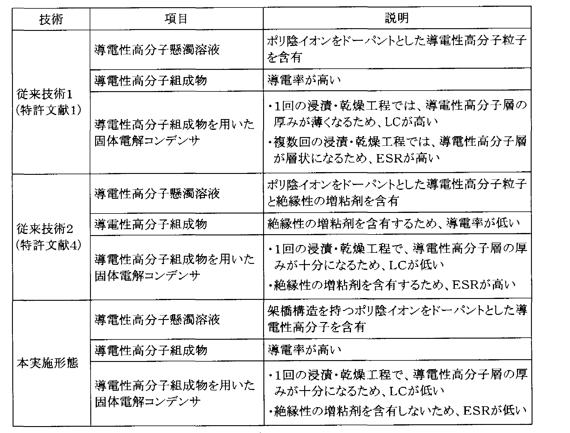
表1に示すように、本実施形態においては、従来技術に対し導電性高分子懸濁溶液の組成が異なり、得られる導電性高分子組成物は異なるものである。本実施形態によれば、導電性高分子組成物を固体電解質層に用いた、ESRが低く、LCも低い固体電解コンデンサを提供することができる。
以下、本実施形態に係る導電性高分子懸濁溶液を用いて形成された導電性高分子組成物、及びその製造方法、並びに導電性高分子組成物を固体電解質層である導電性高分子層に用いた固体電解コンデンサについて詳細に説明する。
本実施形態に係る導電性高分子懸濁溶液に含まれる架橋構造を持つポリ陰イオンの主鎖は、ポリスチレンスルホン酸、ポリビニルスルホン酸、ポリマレイン酸、ポリアクリル酸などのポリ酸であることが好ましい。導電性高分子の溶液への分散性及び導電性の観点から、架橋構造を持つポリ陰イオンの主鎖は、ポリスチレンスルホン酸が特に好ましい。
架橋構造を持つポリ陰イオンは、架橋剤を用いて直鎖構造のポリ陰イオンを架橋した構造を有することが好ましい。このポリ陰イオンの主鎖同士を架橋する架橋剤は、ポリ陰イオンの官能基同士に反応する官能基を2つ以上持つものなら特に限定されないが、例えば、エポキシ基、イソシアネート基、カルボキシル基、アミノ基、ヒドロキシル基、メルカプト基などの官能基を2つ以上持つことが好ましい。エポキシ基を2つ以上持つ架橋剤は、ポリスチレンスルホン酸に含まれるスルホン基と反応性が良いため、特に好ましい。
エポキシ基を2つ以上持つ化合物としては、ソルビトールポリグリシジルエーテル、ポリグリセロールポリグリシジルエーテル、ペンタエリスリトールポリグリシジルエーテル、ジグリセロールポリグリシジルエーテル、グリセロールポリグリシジルエーテル、トリメチロールプロパンポリグリシジルエーテル、レソルシノールジグリシジルエーテル、ネオペンチルグリコールジグリシジルエーテル、1,6-ヘキサンジオールジグリシジルエーテル、ポリエチレングリコールジグリシジルエーテル、ポリプロピレングリコールジグリシジルエーテル、ポリブタジエンジグリシジルエーテル、ジグリシジル-o-フタレート、ハイドロキノンジグリシジルエーテル、ジグリシジルテレフタレート、ジブロモネオペンチルグリコールジグリシジルエーテル、ビスフェノールA系エポキシ樹脂等が挙げられる。
架橋剤は、単独で用いても、2種類以上を任意の割合で併用してもなんら問題ない。
本実施形態に係る導電性高分子懸濁溶液に含まれる導電性高分子は、ピロール、チオフェン、フラン及びこれらの誘導体から選択された少なくとも一種のモノマーを重合して得られたポリマーが好ましいが、導電性及び耐熱性の観点から、3,4-エチレンジオキシチオフェンのポリマーであることが特に好ましい。
本実施形態に係る導電性高分子懸濁溶液に含まれる溶媒は、水;水と、アルコール、アセトン、アセトニトリル、エチレングリコールなどの極性有機溶媒との混合溶媒が好ましいが、導電性高分子懸濁溶液の乾燥工程で発生する溶媒蒸気の排気設備設置の簡易さ、環境負荷の低さ、除去の容易さの観点から、水であることが特に好ましい。
本実施形態に係る導電性高分子懸濁溶液の粘度は、10~1000mPa・sであることが好ましく、固体電解コンデンサにおける導電性高分子層の形成の容易さから、50~500mPa・sであることが特に好ましい。
架橋構造を持つポリ陰イオンと導電性高分子と溶媒とを含む導電性高分子懸濁溶液は、次の四つの工程を経て製造することができる。
(第一の工程)
水系溶媒中で架橋剤とポリ陰イオンを反応させて、架橋構造を持つポリ陰イオンを合成する。この第一工程では、ポリ陰イオンの架橋度を任意に調整可能であるので、任意の粘度を持つ導電性高分子懸濁溶液が得られる利点がある。
水系溶媒中で架橋剤とポリ陰イオンを反応させて、架橋構造を持つポリ陰イオンを合成する。この第一工程では、ポリ陰イオンの架橋度を任意に調整可能であるので、任意の粘度を持つ導電性高分子懸濁溶液が得られる利点がある。
(第二の工程)
有機酸又はその塩からなるドーパントを含む水又は有機溶媒又は水混和有機溶媒中で、導電性高分子を与えるモノマーを、酸化剤を用いて化学酸化重合させて、導電性高分子を含む混合物を得る。導電性高分子は、粒子状であることが好ましい。この第二の工程では、親油性であるモノマーと相溶性の高い溶媒を任意に選択可能であり、またモノスルホン酸をドーパントとして選択可能であることから、重合度及び結晶度の高い導電性高分子が得られる利点がある。
有機酸又はその塩からなるドーパントを含む水又は有機溶媒又は水混和有機溶媒中で、導電性高分子を与えるモノマーを、酸化剤を用いて化学酸化重合させて、導電性高分子を含む混合物を得る。導電性高分子は、粒子状であることが好ましい。この第二の工程では、親油性であるモノマーと相溶性の高い溶媒を任意に選択可能であり、またモノスルホン酸をドーパントとして選択可能であることから、重合度及び結晶度の高い導電性高分子が得られる利点がある。
ドーパントは、ベンゼンスルホン酸、ナフタレンスルホン酸、カンファースルホン酸及びその誘導体、並びにそれら塩から選択されるモノスルホン酸類の少なくとも一種であることが好ましい。
モノマーは、前述の導電性高分子懸濁溶液に含まれる導電性高分子を与えるモノマーを選択すればよく、ピロール、チオフェン、フラン及びこれらの誘導体から選択された少なくとも一種であることが好ましい。
酸化剤としては、特に制限はなく、塩化鉄(III)六水和物、無水塩化鉄(III)、硝酸鉄(III)九水和物、無水硝酸第二鉄、硫酸鉄(III)n水和物(n=3~12)、硫酸鉄(III)アンモニウム十二水和物、過塩素酸鉄(III)n水和物(n=1,6)、テトラフルオロホウ酸鉄(III)等の無機酸の鉄(III)塩;塩化銅(II)、硫酸銅(II)、テトラフルオロホウ酸銅(II)等の無機酸の銅(II)塩;テトラフルオロホウ酸ニトロソニウム;過硫酸アンモニウム、過硫酸ナトリウム、過硫酸カリウム等の過硫酸塩;過ヨウ素酸カリウム等の過ヨウ素酸塩;過酸化水素、オゾン、ヘキサシアノ鉄(III)酸カリウム、硫酸四アンモニウムセリウム(IV)二水和物、臭素、ヨウ素;p-トルエンスルホン酸鉄(III)等の有機酸の鉄(III)塩を用いることができる。中でも、無機酸もしくは有機酸の鉄塩(III)、又は過硫酸塩が好ましく、過硫酸アンモニウム又はp-トルエンスルホン酸鉄(III)がより好ましく、ドーパントを兼ねる性質を有していることから、p-トルエンスルホン酸鉄(III)がさらに好ましい。酸化剤は、1種でもよく、2種以上でもよい。
(第三の工程)
前記混合物から前記導電性高分子を回収する。すなわち、前記導電性高分子を含む混合物から不純物を除去し、導電性高分子を精製する。この第三の工程では、化学酸化重合して得られた導電性高分子を含む反応液から、未反応モノマーや、酸化剤由来の残留金属イオン及び陰ニオンを除去することができ、この精製処理により、高純度の導電性高分子が得られる利点がある。
前記混合物から前記導電性高分子を回収する。すなわち、前記導電性高分子を含む混合物から不純物を除去し、導電性高分子を精製する。この第三の工程では、化学酸化重合して得られた導電性高分子を含む反応液から、未反応モノマーや、酸化剤由来の残留金属イオン及び陰ニオンを除去することができ、この精製処理により、高純度の導電性高分子が得られる利点がある。
(第四の工程)
水系溶媒中で、第一の工程で得られた架橋構造を持つポリ陰イオンと、第三の工程で得られた導電性高分子とを酸化剤で作用させて、導電性高分子懸濁溶液を形成する。この第四の工程では、第一の工程で架橋度が任意に調整されたポリ陰イオンが、第三の工程で精製された導電性高分子にドーピングし、分散性が良好で、粘度が任意に調整された導電性高分子懸濁溶液が得られる利点がある。
水系溶媒中で、第一の工程で得られた架橋構造を持つポリ陰イオンと、第三の工程で得られた導電性高分子とを酸化剤で作用させて、導電性高分子懸濁溶液を形成する。この第四の工程では、第一の工程で架橋度が任意に調整されたポリ陰イオンが、第三の工程で精製された導電性高分子にドーピングし、分散性が良好で、粘度が任意に調整された導電性高分子懸濁溶液が得られる利点がある。
そして、本実施形態に係る導電性高分子組成物は、上記導電性高分子懸濁溶液を乾燥させて形成される。乾燥は、導電性高分子懸濁溶液の溶媒のうち少なくとも90重量%が除去される条件で行えばよく、例えば、溶媒として水を用いた場合は、105~200℃で1~3時間行えばよい。
本実施形態に係る固体電解コンデンサは、前述の導電性高分子組成物を固体電解質層である導電性高分子層に用いること以外は、基本的には従来の固体電解コンデンサの構成とほぼ同様である。即ち、形状、材質等も公知のものが採用でき、特に制限はない。
図1に、本実施形態に係る固体電解コンデンサの構造の一例を示す。図1に示す固体電解コンデンサは、陽極側電極としての弁作用金属1と、この弁作用金属1と外部電極7を繋げる弁作用金属リード8と、弁作用金属1の表面を陽極酸化して得た誘電体酸化皮膜層2と、固体電解質としての導電性高分子層3と、グラファイト層4及び銀層5からなる陰極層と、銀層5と外部電極7を繋げる導電接着剤6と、これらを覆う外装樹脂9から構成されている。
弁作用金属1は、弁作用金属の板、箔又は線;弁作用金属の微粒子からなる焼結体;エッチングによって拡面処理された多孔質体金属などによって形成される。弁作用金属としては、タンタル、アルミニウム、チタン、ニオブ、ジルコニウム及びこれらの合金などが挙げられ、タンタル、アルミニウム及びニオブから選択される少なくとも1種であることが好ましい。
誘電体酸化皮膜層2は、弁作用金属1の表面を電解酸化させることで形成することができる層であり、焼結体や多孔質体などの空孔部にも形成される。誘電体酸化皮膜層2の厚みは、電解酸化の電圧によって適宜調整できる。
導電性高分子層3の厚さは、5μm以上であることが好ましく、5~20μmであることがより好ましい。また、導電性高分子層3は、本実施形態の導電性高分子組成物と、化学酸化重合や電解重合などにより形成される導電性高分子とを併用して形成しても特に問題はない。
以下に、本実施形態を実施例に基づき、さらに具体的に説明するが、本実施形態は、これらの実施例のみに限定されるものではない。
〔実施例1〕
(第一の工程)
ポリ陰イオンである直鎖構造のポリスチレンスルホン酸(重量平均分子量Mw=50000)(20g)と、架橋剤であるソルビトールポリグリシジルエーテル(0.4g)とを、溶媒である水(100mL)に溶解させた。得られた溶液を80℃に保温し、24時間攪拌することで、直鎖構造のポリスチレンスルホン酸とソルビトールポリグリシジルエーテルを反応させて、架橋構造を持つポリ陰イオンを得た。FTIR測定により、直鎖構造のポリスチレンスルホン酸とソルビトールポリグリシジルエーテルとが反応していることを確認した。具体的には、FTIRスペクトルにおいて、1190cm-1付近に見られるスルホン基由来のピークが減少し、1348cm-1付近にスルホン酸エステル基由来のピークが増加していることが確認された。
(第二の工程)
導電性高分子を与えるモノマーである3,4-エチレンジオキシチオフェン(5g)と、ドーパントであるカンファースルホン酸(5g)と、酸化剤及びドーパントして機能するp-トルエンスルホン酸鉄(III)(45g)を、溶媒としてのエタノール(150mL)に溶解させた。得られた溶液を室温下で24時間攪拌して、モノマーの酸化重合を行った。
導電性高分子を与えるモノマーである3,4-エチレンジオキシチオフェン(5g)と、ドーパントであるカンファースルホン酸(5g)と、酸化剤及びドーパントして機能するp-トルエンスルホン酸鉄(III)(45g)を、溶媒としてのエタノール(150mL)に溶解させた。得られた溶液を室温下で24時間攪拌して、モノマーの酸化重合を行った。
(第三の工程)
第二の工程で得られた混合液を減圧ろ過装置でろ過して、導電性高分子粒子を得た。得られた導電性高分子粒子を純水で洗浄して、過剰の酸化剤・ドーパントを除去した。純水による洗浄は、ろ液のpHが6~7になるまで繰り返し行った。ろ液のpHが6~7に達した後、エタノールで洗浄して、モノマー、酸化剤及び反応後の酸化剤(p-トルエンスルホン酸鉄(II))を除去した。エタノールによる洗浄は、ろ液が無色透明となるまで行った。
第二の工程で得られた混合液を減圧ろ過装置でろ過して、導電性高分子粒子を得た。得られた導電性高分子粒子を純水で洗浄して、過剰の酸化剤・ドーパントを除去した。純水による洗浄は、ろ液のpHが6~7になるまで繰り返し行った。ろ液のpHが6~7に達した後、エタノールで洗浄して、モノマー、酸化剤及び反応後の酸化剤(p-トルエンスルホン酸鉄(II))を除去した。エタノールによる洗浄は、ろ液が無色透明となるまで行った。
(第四の工程)
第三の工程で洗浄された導電性高分子粒子(2.5g)を水(50mL)中に分散させた後、第一の工程で得られた架橋構造を持つポリスチレンスルホン酸の20重量%水溶液(16.5g)を添加した。この混合液に、酸化剤としての過硫酸アンモニウム(7.5g)を加えて、室温下で24時間攪拌して反応させた。得られた導電性高分子懸濁溶液の粘度をCBC株式会社製の振動式粘度計(商品名:VM-10A-L)により測定した。
第三の工程で洗浄された導電性高分子粒子(2.5g)を水(50mL)中に分散させた後、第一の工程で得られた架橋構造を持つポリスチレンスルホン酸の20重量%水溶液(16.5g)を添加した。この混合液に、酸化剤としての過硫酸アンモニウム(7.5g)を加えて、室温下で24時間攪拌して反応させた。得られた導電性高分子懸濁溶液の粘度をCBC株式会社製の振動式粘度計(商品名:VM-10A-L)により測定した。
(第五の工程)
第四の工程で得られた導電性高分子懸濁溶液を、ガラス基板上に100μL滴下し、125℃の恒温槽中で1時間乾燥して、導電性高分子組成物膜を形成した。その後、四端子法で、得られた導電性高分子組成物膜の表面抵抗(Ω/□)及び膜厚を計測し、導電率(S/cm)を算出した。
第四の工程で得られた導電性高分子懸濁溶液を、ガラス基板上に100μL滴下し、125℃の恒温槽中で1時間乾燥して、導電性高分子組成物膜を形成した。その後、四端子法で、得られた導電性高分子組成物膜の表面抵抗(Ω/□)及び膜厚を計測し、導電率(S/cm)を算出した。
得られた導電性高分子懸濁溶液の粘度、及び得られた導電性高分子組成物膜の導電率を表2に示す。
〔実施例2〕
第一の工程において、ポリ陰イオンとして直鎖構造のポリマレイン酸(重量平均分子量Mw=50000)を用いた以外は、実施例1と同様にして、導電性高分子懸濁溶液及び導電性高分子組成物膜を製造した。実施例1と同様にして、製造した導電性高分子懸濁溶液の粘度及び製造した導電性高分子組成物膜の導電率を評価した結果を表2に示す。
第一の工程において、ポリ陰イオンとして直鎖構造のポリマレイン酸(重量平均分子量Mw=50000)を用いた以外は、実施例1と同様にして、導電性高分子懸濁溶液及び導電性高分子組成物膜を製造した。実施例1と同様にして、製造した導電性高分子懸濁溶液の粘度及び製造した導電性高分子組成物膜の導電率を評価した結果を表2に示す。
〔実施例3〕
第一の工程において、架橋剤としてソルビトールポリグリシジルエーテル(0.1g)を用いた以外は、実施例1と同様にして、導電性高分子懸濁溶液及び導電性高分子組成物膜を製造した。実施例1と同様にして、製造した導電性高分子懸濁溶液の粘度及び製造した導電性高分子組成物膜の導電率を評価した結果を表2に示す。
第一の工程において、架橋剤としてソルビトールポリグリシジルエーテル(0.1g)を用いた以外は、実施例1と同様にして、導電性高分子懸濁溶液及び導電性高分子組成物膜を製造した。実施例1と同様にして、製造した導電性高分子懸濁溶液の粘度及び製造した導電性高分子組成物膜の導電率を評価した結果を表2に示す。
〔実施例4〕
第一の工程において、架橋剤としてソルビトールポリグリシジルエーテル(2g)を用いた以外は、実施例1と同様にして、導電性高分子懸濁溶液及び導電性高分子組成物膜を製造した。実施例1と同様にして、製造した導電性高分子懸濁溶液の粘度及び製造した導電性高分子組成物膜の導電率を評価した結果を表2に示す。
第一の工程において、架橋剤としてソルビトールポリグリシジルエーテル(2g)を用いた以外は、実施例1と同様にして、導電性高分子懸濁溶液及び導電性高分子組成物膜を製造した。実施例1と同様にして、製造した導電性高分子懸濁溶液の粘度及び製造した導電性高分子組成物膜の導電率を評価した結果を表2に示す。
〔比較例1〕
第一の工程を行わず、第四の工程において直鎖構造のポリスチレンスルホン酸(重量平均分子量Mw=50000)を用いた以外は、実施例1と同様にして、導電性高分子懸濁溶液及び導電性高分子組成物膜を製造した。実施例1と同様にして、製造した導電性高分子懸濁溶液の粘度及び製造した導電性高分子組成物膜の導電率を評価した結果を表2に示す。
第一の工程を行わず、第四の工程において直鎖構造のポリスチレンスルホン酸(重量平均分子量Mw=50000)を用いた以外は、実施例1と同様にして、導電性高分子懸濁溶液及び導電性高分子組成物膜を製造した。実施例1と同様にして、製造した導電性高分子懸濁溶液の粘度及び製造した導電性高分子組成物膜の導電率を評価した結果を表2に示す。
〔比較例2〕
第四の工程で得られた導電性高分子懸濁溶液に、増粘多糖類であるプルラン(6g)を添加して、導電性高分子懸濁溶液の粘度を100mPa・sに調整した以外は、比較例1と同様にして、導電性高分子懸濁溶液及び導電性高分子組成物膜を製造した。実施例1と同様にして、製造した導電性高分子懸濁溶液の粘度及び製造した導電性高分子組成物膜の導電率を評価した結果を表2に示す。
第四の工程で得られた導電性高分子懸濁溶液に、増粘多糖類であるプルラン(6g)を添加して、導電性高分子懸濁溶液の粘度を100mPa・sに調整した以外は、比較例1と同様にして、導電性高分子懸濁溶液及び導電性高分子組成物膜を製造した。実施例1と同様にして、製造した導電性高分子懸濁溶液の粘度及び製造した導電性高分子組成物膜の導電率を評価した結果を表2に示す。

〔実施例5〕
実施例1で製造した導電性高分子懸濁溶液を用いて固体電解コンデンサを製造した。図1に示す固体電解コンデンサの断面図を参照して実施例5について説明する。図1に示すように、実施例5で製造した固体電解コンデンサは、陽極側電極としての弁作用金属1と、この弁作用金属1と外部電極7を繋げる弁作用金属リード8と、弁作用金属1の表面を陽極酸化して得た誘電体酸化皮膜層2と、固体電解質としての導電性高分子層3と、グラファイト層4及び銀層5からなる陰極層と、銀層5と外部電極7を繋げる導電接着剤6と、これらを覆う外装樹脂9から構成されている。なお、弁作用金属1として、タンタル微粉末の焼結体を選択した。
実施例1で製造した導電性高分子懸濁溶液を用いて固体電解コンデンサを製造した。図1に示す固体電解コンデンサの断面図を参照して実施例5について説明する。図1に示すように、実施例5で製造した固体電解コンデンサは、陽極側電極としての弁作用金属1と、この弁作用金属1と外部電極7を繋げる弁作用金属リード8と、弁作用金属1の表面を陽極酸化して得た誘電体酸化皮膜層2と、固体電解質としての導電性高分子層3と、グラファイト層4及び銀層5からなる陰極層と、銀層5と外部電極7を繋げる導電接着剤6と、これらを覆う外装樹脂9から構成されている。なお、弁作用金属1として、タンタル微粉末の焼結体を選択した。
固体電解コンデンサを製造する方法について説明する。弁作用金属1としてのタンタル微粉末の焼結体をリン酸水溶液中で陽極酸化し、タンタル微粉末表面全体が誘電体酸化皮膜層2で被覆された3.6mm×1.8mm×4.5mmのペレットを得た。次に、実施例1で製造した導電性高分子懸濁溶液にペレットを浸漬・引き上げを1回行った後、125℃で反応・乾燥させて、導電性高分子層3を10μmの均一の厚みで形成した。導電性高分子層3の上にグラファイト層4及び銀層5からなる陰極層、導電接着剤6及び外部電極7、並びに外装樹脂9を順番に形成し、容量470μF、外表面積0.616cm2の固体電解コンデンサを製造した。
製造した定格電圧2.5Vの固体電解コンデンサの100kHzの周波数におけるESR及び2.5VのLCを評価した。ESR測定結果を表3に示した。また、LC測定結果は容量C当たりのLCに規格化して、表3に示した。
〔実施例6〕
実施例2で製造した導電性高分子懸濁溶液を用いた以外には、実施例5と同様にして、固体電解コンデンサを製造した。実施例5と同様にして、製造した固体電解コンデンサの100kHzの周波数におけるESR及び2.5VのLCを評価した。ESR測定結果を表3に示した。また、LC測定結果は容量C当たりのLCに規格化して、表3に示した。
実施例2で製造した導電性高分子懸濁溶液を用いた以外には、実施例5と同様にして、固体電解コンデンサを製造した。実施例5と同様にして、製造した固体電解コンデンサの100kHzの周波数におけるESR及び2.5VのLCを評価した。ESR測定結果を表3に示した。また、LC測定結果は容量C当たりのLCに規格化して、表3に示した。
〔実施例7〕
実施例3で製造した導電性高分子懸濁溶液を用いた以外には、実施例5と同様にして、固体電解コンデンサを製造した。実施例5と同様にして、製造した固体電解コンデンサの100kHzの周波数におけるESR及び2.5VのLCを評価した。ESR測定結果を表3に示した。また、LC測定結果は容量C当たりのLCに規格化して、表3に示した。
実施例3で製造した導電性高分子懸濁溶液を用いた以外には、実施例5と同様にして、固体電解コンデンサを製造した。実施例5と同様にして、製造した固体電解コンデンサの100kHzの周波数におけるESR及び2.5VのLCを評価した。ESR測定結果を表3に示した。また、LC測定結果は容量C当たりのLCに規格化して、表3に示した。
〔実施例8〕
実施例4で製造した導電性高分子懸濁溶液を用いた以外には、実施例5と同様にして、固体電解コンデンサを製造した。実施例5と同様にして、製造した固体電解コンデンサの100kHzの周波数におけるESR及び2.5VのLCを評価した。ESR測定結果を表3に示した。また、LC測定結果は容量C当たりのLCに規格化して、表3に示した。
実施例4で製造した導電性高分子懸濁溶液を用いた以外には、実施例5と同様にして、固体電解コンデンサを製造した。実施例5と同様にして、製造した固体電解コンデンサの100kHzの周波数におけるESR及び2.5VのLCを評価した。ESR測定結果を表3に示した。また、LC測定結果は容量C当たりのLCに規格化して、表3に示した。
〔実施例9〕
弁作用金属1として、タンタル微粉末の焼結体を選択した。弁作用金属1としてのタンタル微粉末の焼結体をリン酸水溶液中で陽極酸化し、タンタル微粉末表面全体が誘電体酸化皮膜層2で被覆された、実施例5と同サイズのペレットを得た。次に、酸化剤であるp-トルエンスルホン酸第二鉄の20質量%エタノール溶液に、この誘電体酸化皮膜層2で被覆されたペレットを10分間浸漬し、60℃で30分乾燥させた後、3,4-エチレンジオキシチオフェン溶液に10分間浸漬して室温で30分間保持して3,4-エチレンジオキシチオフェンの化学酸化重合を行った。これら酸化剤溶液への浸漬及び乾燥、3,4-エチレンジオキシチオフェン溶液への浸漬を行う一連の重合操作を5回繰り返して、第1の導電性高分子層を形成した。
弁作用金属1として、タンタル微粉末の焼結体を選択した。弁作用金属1としてのタンタル微粉末の焼結体をリン酸水溶液中で陽極酸化し、タンタル微粉末表面全体が誘電体酸化皮膜層2で被覆された、実施例5と同サイズのペレットを得た。次に、酸化剤であるp-トルエンスルホン酸第二鉄の20質量%エタノール溶液に、この誘電体酸化皮膜層2で被覆されたペレットを10分間浸漬し、60℃で30分乾燥させた後、3,4-エチレンジオキシチオフェン溶液に10分間浸漬して室温で30分間保持して3,4-エチレンジオキシチオフェンの化学酸化重合を行った。これら酸化剤溶液への浸漬及び乾燥、3,4-エチレンジオキシチオフェン溶液への浸漬を行う一連の重合操作を5回繰り返して、第1の導電性高分子層を形成した。
化学酸化重合による第1の導電性高分子層を形成したペレットを、実施例1で製造した導電性高分子懸濁溶液に浸漬・引き上げた後、125℃で反応・乾燥させて、第2の導電性高分子層を形成した。導電性高分子層3の厚みは、第1の導電性高分子層と第2の導電性高分子層を合わせて10μmである。第2の導電性高分子層の上にグラファイト層4及び銀層5からなる陰極層、導電接着剤6及び外部電極7、並びに外装樹脂9を順番に形成し、容量470μF、外表面積0.616cm2の固体電解コンデンサを製造した。
実施例5と同様にして、製造した固体電解コンデンサの100kHzの周波数におけるESR及び2.5VのLCを評価した。ESR測定結果を表3に示した。また、LC測定結果は容量C当たりのLCに規格化して、表3に示した。
〔比較例3〕
比較例1で製造した導電性高分子懸濁溶液を用いた以外には、実施例5と同様にして、固体電解コンデンサを製造した。実施例5と同様にして、製造した固体電解コンデンサの100kHzの周波数におけるESR及び2.5VのLCを評価した。ESR測定結果を表3に示した。また、LC測定結果は容量C当たりのLCに規格化して、表3に示した。
比較例1で製造した導電性高分子懸濁溶液を用いた以外には、実施例5と同様にして、固体電解コンデンサを製造した。実施例5と同様にして、製造した固体電解コンデンサの100kHzの周波数におけるESR及び2.5VのLCを評価した。ESR測定結果を表3に示した。また、LC測定結果は容量C当たりのLCに規格化して、表3に示した。
〔比較例4〕
導電性高分子層の形成方法として、比較例1で製造した導電性高分子懸濁溶液へのペレットの浸漬・乾燥工程を5回行った以外には、実施例5と同様にして、固体電解コンデンサを製造した。実施例5と同様にして、製造した固体電解コンデンサの100kHzの周波数におけるESR及び2.5VのLCを評価した。ESR測定結果を表3に示した。また、LC測定結果は容量C当たりのLCに規格化して、表3に示した。
導電性高分子層の形成方法として、比較例1で製造した導電性高分子懸濁溶液へのペレットの浸漬・乾燥工程を5回行った以外には、実施例5と同様にして、固体電解コンデンサを製造した。実施例5と同様にして、製造した固体電解コンデンサの100kHzの周波数におけるESR及び2.5VのLCを評価した。ESR測定結果を表3に示した。また、LC測定結果は容量C当たりのLCに規格化して、表3に示した。
〔比較例5〕
比較例2で製造した導電性高分子懸濁溶液を用いた以外には、実施例5と同様にして、固体電解コンデンサを製造した。実施例5と同様にして、製造した固体電解コンデンサの100kHzの周波数におけるESR及び2.5VのLCを評価した。ESR測定結果を表3に示した。また、LC測定結果
は容量C当たりのLCに規格化して、表3に示した。
比較例2で製造した導電性高分子懸濁溶液を用いた以外には、実施例5と同様にして、固体電解コンデンサを製造した。実施例5と同様にして、製造した固体電解コンデンサの100kHzの周波数におけるESR及び2.5VのLCを評価した。ESR測定結果を表3に示した。また、LC測定結果
は容量C当たりのLCに規格化して、表3に示した。

表2に示したように、本実施形態に係る導電性高分子懸濁溶液(実施例1~4)は、いずれも比較例1で製造した導電性高分子懸濁溶液よりも高い粘度を有している。また、本実施形態に係る導電性高分子組成物膜(実施例1~4)は、いずれも比較例2で製造した導電性高分子組成物膜よりも高い導電性を示している。導電性高分子懸濁溶液が高い粘度を持ちつつ、導電性高分子懸濁溶液から得られる導電性高分子組成物膜の導電率が損なわれない結果から、本実施形態による効果は、明らかである。これは、架橋構造を持つポリ陰イオンは導電性高分子のドーパントであるため、一般的な絶縁性の増粘剤と全く異なり、導電性高分子懸濁溶液より得られる導電性高分子組成物中に存在していても導電性を低下させることはないためである。また、実施例2の結果と、実施例1、3及び4の結果との比較から、ポリ陰イオンの主鎖としてポリスチレンスルホン酸を用いた方が、ポリマレイン酸を用いた場合よりも導電率が良いことが分かる。
また表3から、本実施形態に係る導電性高分子組成物を導電性高分子層として用いた固体電解コンデンサ(実施例5~9)においては、比較例3~5で製造した固体電解コンデンサに比べて、低いESRと低いLCが両立している。ESRが低い理由は、絶縁性の増粘剤を導電性高分子層に含まないこと、かつ導電性高分子層が1回の導電性高分子懸濁溶液への浸漬・乾燥工程でのみ形成でき、導電性高分子層が層状にならないことにより、界面抵抗が発生しないためである。また、LCが低い理由は、導電性高分子懸濁溶液が高い粘度を持っているため、1回の導電性高分子懸濁溶液への浸漬・乾燥工程で十分な厚み(5μm以上)の導電性高分子層が形成されるためである。実施例5及び9の結果と、実施例7及び8の結果との比較から、LC低下の観点からは導電性高分子層の厚みが5μmよりも大きいことが好ましく、ESR低下の観点からは導電性高分子層の厚みが35μmよりも小さいことが好ましい。実施例5の結果と、実施例9の結果との比較から、導電性高分子層の形成には、導電性高分子懸濁溶液から得られる導電性高分子組成物と化学酸化重合から得られる導電性高分子組成物との併用でもなんら問題がない。
この出願は、2009年2月3日に出願された日本特許出願特願2009-022110を基礎とする優先権を主張し、その開示の全てを参照してここに取り込む。
1 弁作用金属
2 誘電体酸化皮膜層
3 導電性高分子層
4 グラファイト層
5 銀層
6 導電接着剤
7 外部電極
8 弁作用金属リード
9 外装樹脂
2 誘電体酸化皮膜層
3 導電性高分子層
4 グラファイト層
5 銀層
6 導電接着剤
7 外部電極
8 弁作用金属リード
9 外装樹脂
Claims (11)
- 架橋構造を持つポリ陰イオンと導電性高分子と溶媒とを含む導電性高分子懸濁溶液を乾燥させて形成することを特徴とする導電性高分子組成物。
- 前記架橋構造を持つポリ陰イオンの主鎖が、ポリスチレンスルホン酸であることを特徴とする請求項1に記載の導電性高分子組成物。
- 前記架橋構造を持つポリ陰イオンが、架橋剤を用いて直鎖構造のポリスチレンスルホン酸を架橋した構造を有することを特徴とする請求項2に記載の導電性高分子組成物。
- 前記架橋剤が、エポキシ基を2つ以上持つ化合物であることを特徴とする請求項3に記載の導電性高分子組成物。
- 前記導電性高分子が、ピロール、チオフェン、フラン及びこれらの誘導体から選択された少なくとも一種のモノマーを重合して得られたポリマーであることを特徴とする請求項1乃至4のいずれかに記載の導電性高分子組成物。
- 前記導電性高分子懸濁溶液の粘度が、10~1000mPa・sであることを特徴とする請求項1乃至5のいずれかに記載の導電性高分子組成物。
- 水系溶媒中で架橋剤とポリ陰イオンを反応させて、架橋構造を持つポリ陰イオンを合成する第一の工程と、
有機酸又はその塩からなるドーパントを含む溶媒中で、導電性高分子を与えるモノマーを、酸化剤を用いて化学酸化重合させて、導電性高分子を含む混合物を得る第二の工程と、
前記混合物から前記導電性高分子を回収する第三の工程と、
前記水系溶媒中で、前記架橋構造を持つポリ陰イオンと前記導電性高分子とを酸化剤で作用させて、導電性高分子懸濁溶液を形成する第四の工程と、
前記導電性高分子懸濁溶液を乾燥させる第五の工程と
を有することを特徴とする導電性高分子組成物の製造方法。 - 前記ドーパントが、ベンゼンスルホン酸、ナフタレンスルホン酸、カンファースルホン酸及びその誘導体、並びにそれらの塩から選択されるモノスルホン酸類の少なくとも一種であることを特徴とする請求項7に記載の導電性高分子組成物の製造方法。
- 前記モノマーが、ピロール、チオフェン、フラン及びこれらの誘導体から選択された少なくとも一種であることを特徴とする請求項7又は8に記載の導電性高分子組成物の製造方法。
- 請求項1乃至6のいずれかに記載の導電性高分子組成物を固体電解質層である導電性高分子層に用いることを特徴とする固体電解コンデンサ。
- 弁作用金属からなる陽極導体の表面に形成された誘電体皮膜層の上に、前記固体電解質層である前記導電性高分子層として、前記導電性高分子組成物を5μm以上の厚みに形成することを特徴とする請求項10に記載の固体電解コンデンサ。
Priority Applications (3)
| Application Number | Priority Date | Filing Date | Title |
|---|---|---|---|
| EP10738537A EP2395514A1 (en) | 2009-02-03 | 2010-02-03 | Electrically conductive polymer composition and process for production thereof, and solid electrolytic capacitor utilizing electrically conductive polymer composition |
| US13/147,313 US8804312B2 (en) | 2009-02-03 | 2010-02-03 | Electroconductive polymer composition, method for producing the same, and solid electrolytic capacitor using electroconductive polymer composition |
| CN2010800064516A CN102308339A (zh) | 2009-02-03 | 2010-02-03 | 导电聚合物组合物,其制备方法和使用导电聚合物组合物的固体电解电容器 |
Applications Claiming Priority (2)
| Application Number | Priority Date | Filing Date | Title |
|---|---|---|---|
| JP2009022110A JP2010182426A (ja) | 2009-02-03 | 2009-02-03 | 導電性高分子組成物およびその製造方法、並びに導電性高分子組成物を用いた固体電解コンデンサ |
| JP2009-022110 | 2009-02-03 |
Publications (1)
| Publication Number | Publication Date |
|---|---|
| WO2010090206A1 true WO2010090206A1 (ja) | 2010-08-12 |
Family
ID=42542099
Family Applications (1)
| Application Number | Title | Priority Date | Filing Date |
|---|---|---|---|
| PCT/JP2010/051486 WO2010090206A1 (ja) | 2009-02-03 | 2010-02-03 | 導電性高分子組成物及びその製造方法、並びに導電性高分子組成物を用いた固体電解コンデンサ |
Country Status (5)
| Country | Link |
|---|---|
| US (1) | US8804312B2 (ja) |
| EP (1) | EP2395514A1 (ja) |
| JP (1) | JP2010182426A (ja) |
| CN (1) | CN102308339A (ja) |
| WO (1) | WO2010090206A1 (ja) |
Cited By (3)
| Publication number | Priority date | Publication date | Assignee | Title |
|---|---|---|---|---|
| EP2327743A1 (en) * | 2009-11-26 | 2011-06-01 | NEC Tokin Corporation | Conductive polymer suspension and method for producing the same, conductive polymer material, electrolytic capacitor, and solid electrolytic capacitor and method for producing the same |
| JP2012222146A (ja) * | 2011-04-08 | 2012-11-12 | Nec Tokin Corp | 導電性高分子懸濁水溶液およびその製造方法、導電性有機材料、ならびに固体電解コンデンサおよびその製造方法 |
| CN103534318A (zh) * | 2011-05-17 | 2014-01-22 | Nec东金株式会社 | 导电性聚合物悬浮液及其制备方法,导电性聚合物材料以及电解电容器及其制备方法 |
Families Citing this family (11)
| Publication number | Priority date | Publication date | Assignee | Title |
|---|---|---|---|---|
| JP5177669B2 (ja) * | 2008-10-15 | 2013-04-03 | Necトーキン株式会社 | 導電性高分子組成物およびそれを用いた固体電解コンデンサ |
| JPWO2011121995A1 (ja) | 2010-03-31 | 2013-07-04 | 日本ケミコン株式会社 | 固体電解コンデンサ |
| JP5788282B2 (ja) * | 2011-09-29 | 2015-09-30 | Necトーキン株式会社 | 固体電解コンデンサおよびその製造方法 |
| JP5902926B2 (ja) * | 2011-11-25 | 2016-04-13 | Necトーキン株式会社 | 導電性高分子組成物、導電性高分子材料、導電性基材、電極および固体電解コンデンサ |
| AU2013249144B2 (en) * | 2012-04-18 | 2016-09-29 | The Arizona Board Of Regents, A Body Corporate Acting For & On Behalf Of Northern Arizona University | Structural supercapacitors |
| CN103570945B (zh) * | 2012-07-27 | 2016-02-24 | 远东新世纪股份有限公司 | 制造导电聚合物分散液的方法、导电聚合物材料及利用所述导电聚合物材料的固态电容 |
| WO2014048543A1 (de) * | 2012-09-25 | 2014-04-03 | Merck Patent Gmbh | Formulierungen enthaltend leitfähige polymere sowie deren verwendung in organischen, elektronischen vorrichtungen |
| JP6161433B2 (ja) * | 2013-06-28 | 2017-07-12 | 株式会社トーキン | 導電性高分子溶液、導電性高分子材料および固体電解コンデンサ |
| WO2019064194A1 (en) | 2017-09-26 | 2019-04-04 | Bansal Sanjay | SYSTEM AND METHOD FOR PROVIDING A VIDEO CONFERENCE FACILITY |
| CN113674998B (zh) * | 2021-07-23 | 2022-10-25 | 益阳市万京源电子有限公司 | 一种耐高压的固态铝电解电容器及其制备方法 |
| KR20240006926A (ko) | 2022-07-07 | 2024-01-16 | 건국대학교 글로컬산학협력단 | 에폭시기 기반 리튬이온전지용 겔 고분자 전해질의 제조방법 및 이에 따라 제조된 겔 고분자 전해질 |
Citations (9)
| Publication number | Priority date | Publication date | Assignee | Title |
|---|---|---|---|---|
| JPH0477675B2 (ja) | 1983-10-12 | 1992-12-09 | Ricoh Kk | |
| JP2636968B2 (ja) | 1990-02-08 | 1997-08-06 | バイエル・アクチエンゲゼルシヤフト | 新規ポリチオフエンの溶液及びその製造方法 |
| JP3251208B2 (ja) | 1997-07-24 | 2002-01-28 | 富山日本電気株式会社 | 固体電解コンデンサの製造方法 |
| JP2003213148A (ja) | 2002-01-18 | 2003-07-30 | Mitsubishi Rayon Co Ltd | 導電性組成物、導電体形成方法及び静電塗装方法 |
| JP2006156890A (ja) * | 2004-09-22 | 2006-06-15 | Shin Etsu Polymer Co Ltd | コンデンサ及びその製造方法 |
| JP2006228679A (ja) * | 2005-02-21 | 2006-08-31 | Nec Tokin Corp | 導電性高分子組成物およびそれを用いた固体電解コンデンサ |
| JP2007045932A (ja) * | 2005-08-10 | 2007-02-22 | Shin Etsu Polymer Co Ltd | 導電性高分子塗料および導電性塗膜 |
| JP2008253012A (ja) * | 2007-03-29 | 2008-10-16 | Tdk Corp | 高分子アクチュエータ及びその製造方法 |
| JP2009022110A (ja) | 2007-07-12 | 2009-01-29 | Yamaha Motor Co Ltd | リレー溶着判定装置および電動車両 |
Family Cites Families (3)
| Publication number | Priority date | Publication date | Assignee | Title |
|---|---|---|---|---|
| US6190805B1 (en) * | 1997-09-10 | 2001-02-20 | Showa Denko Kabushiki Kaisha | Polymerizable compound, solid polymer electrolyte using the same and use thereof |
| JP4077675B2 (ja) | 2002-07-26 | 2008-04-16 | ナガセケムテックス株式会社 | ポリ(3,4−ジアルコキシチオフェン)とポリ陰イオンとの複合体の水分散体およびその製造方法 |
| EP1524678B2 (de) * | 2003-10-17 | 2018-06-20 | Heraeus Deutschland GmbH & Co. KG | Elektrolytkondensatoren mit polymerer Aussenschicht |
-
2009
- 2009-02-03 JP JP2009022110A patent/JP2010182426A/ja active Pending
-
2010
- 2010-02-03 US US13/147,313 patent/US8804312B2/en not_active Expired - Fee Related
- 2010-02-03 WO PCT/JP2010/051486 patent/WO2010090206A1/ja active Application Filing
- 2010-02-03 CN CN2010800064516A patent/CN102308339A/zh active Pending
- 2010-02-03 EP EP10738537A patent/EP2395514A1/en not_active Withdrawn
Patent Citations (9)
| Publication number | Priority date | Publication date | Assignee | Title |
|---|---|---|---|---|
| JPH0477675B2 (ja) | 1983-10-12 | 1992-12-09 | Ricoh Kk | |
| JP2636968B2 (ja) | 1990-02-08 | 1997-08-06 | バイエル・アクチエンゲゼルシヤフト | 新規ポリチオフエンの溶液及びその製造方法 |
| JP3251208B2 (ja) | 1997-07-24 | 2002-01-28 | 富山日本電気株式会社 | 固体電解コンデンサの製造方法 |
| JP2003213148A (ja) | 2002-01-18 | 2003-07-30 | Mitsubishi Rayon Co Ltd | 導電性組成物、導電体形成方法及び静電塗装方法 |
| JP2006156890A (ja) * | 2004-09-22 | 2006-06-15 | Shin Etsu Polymer Co Ltd | コンデンサ及びその製造方法 |
| JP2006228679A (ja) * | 2005-02-21 | 2006-08-31 | Nec Tokin Corp | 導電性高分子組成物およびそれを用いた固体電解コンデンサ |
| JP2007045932A (ja) * | 2005-08-10 | 2007-02-22 | Shin Etsu Polymer Co Ltd | 導電性高分子塗料および導電性塗膜 |
| JP2008253012A (ja) * | 2007-03-29 | 2008-10-16 | Tdk Corp | 高分子アクチュエータ及びその製造方法 |
| JP2009022110A (ja) | 2007-07-12 | 2009-01-29 | Yamaha Motor Co Ltd | リレー溶着判定装置および電動車両 |
Cited By (4)
| Publication number | Priority date | Publication date | Assignee | Title |
|---|---|---|---|---|
| EP2327743A1 (en) * | 2009-11-26 | 2011-06-01 | NEC Tokin Corporation | Conductive polymer suspension and method for producing the same, conductive polymer material, electrolytic capacitor, and solid electrolytic capacitor and method for producing the same |
| JP2012222146A (ja) * | 2011-04-08 | 2012-11-12 | Nec Tokin Corp | 導電性高分子懸濁水溶液およびその製造方法、導電性有機材料、ならびに固体電解コンデンサおよびその製造方法 |
| CN103534318A (zh) * | 2011-05-17 | 2014-01-22 | Nec东金株式会社 | 导电性聚合物悬浮液及其制备方法,导电性聚合物材料以及电解电容器及其制备方法 |
| US9455092B2 (en) | 2011-05-17 | 2016-09-27 | Nec Tokin Corporation | Electric conductive polymer suspension and method for producing the same, electric conductive polymer material, and electrolytic capacitor and method for producing the same |
Also Published As
| Publication number | Publication date |
|---|---|
| JP2010182426A (ja) | 2010-08-19 |
| EP2395514A1 (en) | 2011-12-14 |
| US20120120557A1 (en) | 2012-05-17 |
| CN102308339A (zh) | 2012-01-04 |
| US8804312B2 (en) | 2014-08-12 |
Similar Documents
| Publication | Publication Date | Title |
|---|---|---|
| WO2010090206A1 (ja) | 導電性高分子組成物及びその製造方法、並びに導電性高分子組成物を用いた固体電解コンデンサ | |
| US9793058B2 (en) | Capacitor with charge time reducing additives and work function modifiers | |
| JP4903759B2 (ja) | 導電性高分子懸濁液およびその製造方法、導電性高分子材料、電解コンデンサ、ならびに固体電解コンデンサおよびその製造方法 | |
| JP5177669B2 (ja) | 導電性高分子組成物およびそれを用いた固体電解コンデンサ | |
| JP4903760B2 (ja) | 導電性高分子懸濁液およびその製造方法、導電性高分子材料、電解コンデンサ、ならびに固体電解コンデンサおよびその製造方法 | |
| JP4454041B2 (ja) | 導電性組成物の分散液、導電性組成物およびその用途 | |
| EP1030324B1 (en) | Sheet capacitor element and laminated solid electrolytic capacitor | |
| JP4983744B2 (ja) | 固体電解コンデンサの製造方法 | |
| JP2010275378A (ja) | 導電性高分子懸濁液およびその製造方法、導電性高分子材料並びに、固体電解コンデンサおよびその製造方法 | |
| JP6017148B2 (ja) | 導電性高分子懸濁溶液、導電性高分子材料、ならびに電解コンデンサおよびその製造方法 | |
| JP2013122016A (ja) | 導電性高分子組成物、導電性高分子材料、導電性基材、電極および固体電解コンデンサ | |
| JP6016780B2 (ja) | 導電性高分子溶液及びその製造方法、導電性高分子材料、ならびにそれを用いた固体電解コンデンサ及びその製造方法 | |
| WO2012137968A1 (ja) | 導電性高分子懸濁水溶液およびその製造方法、導電性有機材料、ならびに固体電解コンデンサおよびその製造方法 | |
| JP6266241B2 (ja) | 導電性ポリマー組成物、及びその製造方法 | |
| JP6223703B2 (ja) | 導電性高分子溶液及びその製造方法、導電性高分子材料、ならびに固体電解コンデンサ | |
| JP2013089648A (ja) | 導電性高分子懸濁液およびその製造方法、導電性高分子材料、固体電解コンデンサおよびその製造方法 | |
| US10522296B2 (en) | Capacitor with charge time reducing additives and work function modifiers | |
| JP6417452B2 (ja) | 導電性ポリマー及びその製造方法 | |
| JP2012104851A (ja) | 導電性高分子懸濁液およびその製造方法、導電性高分子材料、電解コンデンサ、ならびに固体電解コンデンサおよびその製造方法 | |
| JP2010143996A (ja) | 導電性高分子とそれを用い固体電解コンデンサ及びその製造方法 | |
| JP5062694B2 (ja) | 導電性高分子製造用酸化剤、それを用いた固体電解コンデンサとその製造方法 | |
| JP2012104850A (ja) | 導電性高分子懸濁液およびその製造方法、導電性高分子材料、電解コンデンサ、ならびに固体電解コンデンサおよびその製造方法 | |
| JPS63253614A (ja) | 固体電解コンデンサとその製造方法 |
Legal Events
| Date | Code | Title | Description |
|---|---|---|---|
| WWE | Wipo information: entry into national phase |
Ref document number: 201080006451.6 Country of ref document: CN |
|
| 121 | Ep: the epo has been informed by wipo that ep was designated in this application |
Ref document number: 10738537 Country of ref document: EP Kind code of ref document: A1 |
|
| WWE | Wipo information: entry into national phase |
Ref document number: 2010738537 Country of ref document: EP |
|
| NENP | Non-entry into the national phase |
Ref country code: DE |
|
| WWE | Wipo information: entry into national phase |
Ref document number: 13147313 Country of ref document: US |