WO2010074022A1 - 鉄道車両用外幌の構造 - Google Patents
鉄道車両用外幌の構造 Download PDFInfo
- Publication number
- WO2010074022A1 WO2010074022A1 PCT/JP2009/071228 JP2009071228W WO2010074022A1 WO 2010074022 A1 WO2010074022 A1 WO 2010074022A1 JP 2009071228 W JP2009071228 W JP 2009071228W WO 2010074022 A1 WO2010074022 A1 WO 2010074022A1
- Authority
- WO
- WIPO (PCT)
- Prior art keywords
- hood
- shoulder
- base portion
- thickness
- cross
- Prior art date
- Legal status (The legal status is an assumption and is not a legal conclusion. Google has not performed a legal analysis and makes no representation as to the accuracy of the status listed.)
- Ceased
Links
Images

















Classifications
-
- B—PERFORMING OPERATIONS; TRANSPORTING
- B61—RAILWAYS
- B61D—BODY DETAILS OR KINDS OF RAILWAY VEHICLES
- B61D17/00—Construction details of vehicle bodies
- B61D17/04—Construction details of vehicle bodies with bodies of metal; with composite, e.g. metal and wood body structures
- B61D17/20—Communication passages between coaches; Adaptation of coach ends therefor
- B61D17/22—Communication passages between coaches; Adaptation of coach ends therefor flexible, e.g. bellows
Definitions
- the present invention relates to the structure of an outer hood for a railway vehicle.
- an inner hood that forms a crossing passage is provided in a space of a connecting portion between vehicle bodies in a railway vehicle, and noise generated when the vehicle travels is radiated from between the vehicle bodies to the outside of the vehicle body on both sides of the inner hood.
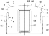
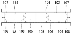
- an inner hood 106 that constitutes a passage 105 is provided between the end face 102 of one connected body 101 and the end face 104 of the other body 103. 42, on the both outer sides in the horizontal direction of the inner hood 106 in FIG. 42, spaced apart from the inner hood 106, and having a flexibility with a U-shaped cross section projecting from the end face 102 of one vehicle body 101.
- the outer hood 107 and the other outer hood 108 having a flexible shape with a U-shaped cross section projecting from the end face 104 of the other vehicle body 103 are provided. As shown in FIG.
- the outer hood 107 is provided only in a range along the substantially upright portion that is both sides of the vehicle body 101 on the wife surface 102, that is, in the range of the side portion 111 of the wife surface. It is not provided in the range of the shoulder portion (shoulder portion of the vehicle body) 112 and the roof portion 113 of the surface 102. Although not shown, this is the same for the other outer hood 108.
- noise emission in the horizontal direction of the vehicle body from the inside of the connecting portion space 114 is suppressed, but noise from the inside of the connecting portion space 114 is indicated by an arrow through the opening portion 115 of the shoulder portion 112.
- K Like K, it is radiated to the outside and affects the outside of the vehicle.
- noise is radiated as indicated by an arrow L from the open portion 116 on the roof side, and it is preferable to suppress radiation of these noises.
- the outer hoods 107 and 108 are not only arranged on the left and right sides of the body surface of the vehicle body, but also as shown in FIG.
- a curved shoulder hood 201 bulging outward is extended, and further along the roof edge of the wife surface (vehicle body) from the end of the shoulder hood 201
- Patent Document 1 discloses a technique in which a roof side hood portion 202 is extended to reduce noise from the opening portion 115 of the shoulder portion 112 of the end face and the opening portion 116 on the roof side.
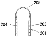
- the outer hood shown in FIG. 44 has a U-shaped cross section, and its base portions 203 and 204 are formed of a thick and rigid wall, and the front portion 205 can be formed. In order to enhance the flexibility, it is formed thinner than the bases 203 and 204 on both sides.
- the outer hood having such a cross-sectional shape is used in the shoulder hood portion 201 as shown in FIG. Arise.
- the shoulder hood portion 201 of the outer hood has a curved shape in which the side hood portion 200 and the roof side hood portion 202 are integrally continuous, so that it is difficult to be flexibly deformed.
- an object of the present invention is to provide a structure for improving the durability of the curved shoulder hood, and to provide a highly durable outer hood for a railway vehicle.
- the present invention is an outer hood that is attached to the end face of the vehicle body, and that is constituted by an inner base portion, an outer base portion, and a tip portion that connects these tips in a cross section.
- the outer hood in which a side hood portion along the side edge of the wife surface and a shoulder hood portion curved at the shoulder portion of the wife surface are connected, at least one hole or notch is formed inside the shoulder hood portion. It is formed.
- the present invention according to claim 2 comprises an outer hood attached to the end face of the vehicle body, comprising a side hood portion along a side edge of the end face, and a shoulder hood portion curved at the shoulder portion of the end face.
- the cross-sectional shape of the side hood part and the shoulder hood part is formed in a U shape with an inner base part, an outer base part, and a tip part connecting these tips, At least one hole or notch is formed in the inner base of the hood.
- the present invention according to claim 3 is the invention according to claim 1 or 2, wherein the thickness of the tip portion of the side hood portion is thinner than the thickness of the inner base portion and the outer base portion of the side hood portion, The thickness of the inner base portion, the outer base portion, and the tip portion of the shoulder hood portion is smaller than the thickness of the inner base portion and the outer base portion of the side hood portion.
- the present invention according to claim 4 is the invention according to claim 1 or 2, wherein the thickness of the tip portion of the side hood portion is formed thinner than the thickness of the inner base portion and the outer base portion of the side hood portion,
- the thickness of the front part of the shoulder hood part is made equal to the thickness of the front part of the side hood part, and the thickness of the inner base part and the outer base part of the shoulder hood part is made equal to the inner base part and the outer base part of the side hood part. It is characterized by being equivalent to the wall thickness of.
- the invention according to claim 5 is the invention according to any one of claims 1 to 4, wherein one or a plurality of the holes or notches are provided in the shoulder hood part. It is.
- the present invention according to claim 6 is the invention according to any one of claims 1 to 5, wherein an upper portion of the shoulder hood portion opposite to the side hood portion is arranged along the roof edge of the wife surface.
- the hood part is extended, and the cross-sectional shape of the upper hood part is formed to be equal to the cross-sectional shape of the side hood part.
- a roof side hood along the roof edge of the wife surface is disposed on the side of the upper hood portion opposite to the shoulder hood portion, and the roof side.
- the cross-sectional shape of the hood is formed to be equal to the cross-sectional shape of the side hood, and the roof hood and the upper hood cover the entire upper part of the connecting space of the vehicle. Is.
- the shoulder hood part since the hole or notch is formed inside the shoulder hood part, the shoulder hood part is easily deformed, and the wrinkles generated in the part are reduced and reduced. In addition, it is possible to increase the durability of the outer hood by reducing the occurrence of cracks.
- the outer base portion, the inner base portion, and the tip portion of the shoulder hood portion are formed thin to enhance flexibility, and the hole or notch is formed in the inner base portion.
- the flexibility of the part becomes extremely high, and the shoulder hood part can be easily deformed to enhance the durability of the outer hood.
- the thickness of the inner base portion of the shoulder hood portion is thicker than the thickness of the inner base portion of the invention of claim 3, but a hole or notch is formed in the inner base portion.
- FIG. 3 is a partial front view of the outer hood on the left side of the body face in FIG. 2. Sectional drawing along the BB line of the outer hood of FIG. Sectional drawing along CC line of the outer hood of FIG. The arrow directional view from the D direction of the outer hood of FIG. FIG. 6 is a front sectional view of the outer hood cut along the EE part of FIG. 5 in the front view of FIG. 4.
- FIG. 3 is an enlarged sectional view taken along line FF in FIG.
- FIG. 3 is an enlarged sectional view taken along line GG in FIG. 2.
- FIG. 3 is an enlarged sectional view taken along line HH in FIG. 2.
- positioning state by the side of one vehicle body of the outer hood in Example 1 of this invention is shown.
- positioning state by the side of the other vehicle body of the outer hood in Example 1 of this invention is shown.
- FIG. 10 is a partial front view of the left hood of the outer hood according to the tenth embodiment of the present invention on the left side of the body surface corresponding to FIG. 4.
- FIG. 22 is an enlarged cross-sectional view of the outer hood along the line B′-B ′ in FIG.
- FIG. 22 is an enlarged cross-sectional view along the line C′-C ′ of the outer hood in FIG. 21.
- the top view of the connection part between the vehicle bodies which shows the arrangement
- the front view which looked at the wife surface of the vehicle body from the II line
- positioning state by the side of one vehicle body of the outer hood in FIG. 25 is shown.
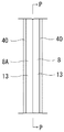
- FIG. 29 is a front view of a connecting portion between vehicle bodies as seen from the PP line of FIG.
- FIG. 31 is a sectional view taken along line FF in FIG. 30.
- FIG. 31 is a sectional view taken along line GG in FIG. 30.
- FIG. 31 is a sectional view taken along the line HH in FIG. 30.
- the top view of the connection part between vehicle bodies which shows the outer hood by Example 14 of this invention.
- FIG. 37 is a sectional view taken along line SS in FIG. 36.
- FIG. 37 is a sectional view taken along line TT in FIG. 36.
- FIG. 37 is a cross-sectional view taken along the line U-U in FIG. 36.
- FIG. 45 is an enlarged cross-sectional view of the outer hood of FIG. 44 taken along line NN.
- FIG. 1 to 12 show a first embodiment of an outer hood according to the present invention.
- 1 to 3 show a state in which the outer hood of the present invention is attached to the end face of a vehicle body of a railway vehicle,
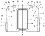
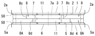
- FIG. 1 is a side view of a connecting portion between the vehicle bodies, and
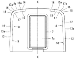
- FIG. The front view of the connection part seen from the surface side, FIG. 3 is the top view.
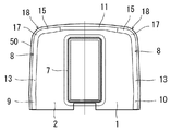
- a bellows-shaped inner hood 7 is installed between the entrance / exit 3 of the end face 2 of the connected vehicle body 1 and the entrance / exit 6 of the end face 5 of the other vehicle body 4.
- a passage 7 a is formed in the inner hood 7.
- the outer surface 8 of the one body 1 is provided with one outer hood 8 located outside the inner hood 7 and on the outer periphery of the inner surface 2. Yes.
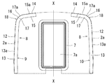
- the one outer hood 8 is divided into three members, a left hood 9, a right hood 10, and a roof hood 11 in FIG.
- the left hood 9 includes a side hood portion 13 which is located on the inner side along the left edge 2a (the left side surface 12 of the vehicle body) of the wife surface 2 in FIG.
- An upper hood portion 15 which is located on the inner side along the roof edge 2a (the roof surface 14 of the vehicle body) and is formed so as to face the inner side of the vehicle body wife surface (center XX of the wife surface) in a substantially horizontal direction.
- a shoulder hood that is curved and joined between the side hood portion 13 and the upper hood portion 15 so as to be located inside the shoulder surface 16 of the vehicle body and bulge outward at the shoulder portion 18 of the wife surface 2.
- the side hood part 13, the upper hood part 15, and the shoulder hood part 17 are formed continuously.
- a shoulder hood portion 17 having a center O (see FIG. 4) on the center side of the wife surface and curved so as to bulge outward is provided at the upper portion of the side hood portion 13 that rises in a substantially vertical direction.
- an upper hood portion 15 is extended on the upper portion of the shoulder hood portion 17 in a substantially horizontal direction so as to be directed toward the inside of the wife surface (center XX of the wife surface).
- the shoulder surface 16 of the vehicle body is formed in a curved surface
- the shoulder hood portion 17 of the outer hood is formed in a curved shape along the curved surface.
- the left hood 9 has the side hood part 13, the upper hood part 15 and the shoulder hood part 17 in a U-shaped cross-sectional shape which will be described later, and a series of shapes shown in FIG.
- the side hood part 13 and the upper hood part 15 which are integrally formed by molding, or formed by bending a flat plate into a U shape, and a shoulder hood part 17 which is molded into a U-shaped cross-sectional shape are shown in FIG. It is formed by connecting to the shape as shown in FIG.
- the left hood 9 is formed of a flexible elastic material such as synthetic rubber.
- the right hood 10 is formed symmetrically with respect to the left hood 9 about the center XX of the end face 2 of the vehicle body 1, and the structure is the left side. It is the same as the hood 9. Therefore, the right hood 10 is denoted by the same reference numeral as that of the left hood 9, and the description thereof is omitted.
- the horizontal length of the upper hood 15 in the right hood 10 is slightly shorter than the upper hood 15 of the left hood 9.
- the roof side hood 11 is disposed between the tip of the upper hood portion 15 of the left hood 9 and the tip of the upper hood portion 15 of the right hood 10 as shown in FIG.
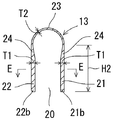
- the cross-sectional shape (cross-sectional view taken along the line BB) of the side hood portion 13 of the left hood 9 shown in FIG. 4 is formed in a U shape having an opening 20 on the base end side, as shown in FIG. That is, a plate-like inner base portion 21 and a plate-like outer base portion 22 arranged in parallel with a predetermined interval, and a tapered shape connecting the tips of both the base portions 21 and 22 (substantially semicircular in the illustrated embodiment). Shape) tip portion 23.
- both base parts 21 and 22 are formed in the thick wall T1 which is large in rigidity and small in flexibility in order to maintain the protruding state from the wife face when it is attached to the wife face.
- the base 23 is formed to be thinner T2 than the bases 21 and 22, and the tip 23 is formed with lower rigidity and greater flexibility than the bases 21 and 22.
- the connection part 24 from the base parts 21 and 22 to the front part 23 is formed so that wall thickness may decrease gradually.
- the cross-sectional shape of the upper hood part 15 (cross-sectional line BB in FIG. 4) is the same as the cross-sectional shape of the side hood part 13 shown in FIG. 5 (cross-sectional line BB in FIG. 4).
- the inner base portion 21 and the outer base portion 22 fixed to each other and the tip portion 23 connecting these tips are formed in a U-shape, and the thickness thereof is also formed in the same manner.
- the shape and other dimensions may vary depending on the structure of the end face.
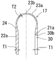
- the cross-sectional shape of the shoulder hood portion 17 (cross-sectional view taken along the line CC in FIG. 4) is formed in a U shape having an opening 20 on the base end side, and the outer peripheral shape thereof is 5 is the same shape as the outer periphery of the side hood part 13 shown in FIG. Further, the thickness of the plate-like inner base portion 21a and the plate-like outer base portion 22a is formed to be equal to the thickness T2 of the tip portion 23 of the side hood portion 13 shown in FIG. 5, and further, the tip portion 23a. Is formed to be equivalent to the thickness T2 of the tip 23 in FIG.
- the thickness T2 of the inner base portion 21a, the outer base portion 22a, and the tip portion 23a in the shoulder hood portion 17 is formed to be thinner than the thickness T1 of the inner base portion 21 and the outer base portion 22 of the side hood portion 13 and the upper hood portion 15.
- the entire curved portion R shown in FIG. 4 in the shoulder hood portion 17 is formed thin, and is more flexible than the side hood portion 13 and the upper hood portion 15.
- the thickness of the base portion of the connecting portion 25 from the thin portion of the shoulder hood portion 17 to the side hood portion 13 and the upper hood portion 15 is gradually increased as shown in FIG.
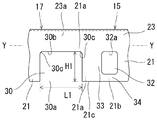
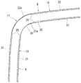
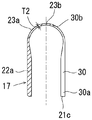
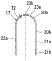
- a cutout 30 penetrating inward and outward in the inner base portion 21a is formed in the inner base portion 21a of the shoulder hood portion 17.
- the notch 30 has an inner base portion 21a in the inner base portion 21a of the shoulder hood portion 17 so as to have an opening 30a on the attachment side to the vehicle body, that is, on the end face 21c side of the base end portion 21b. It is formed of one notch 30 with a part of the notch cut out.
- the length L1 and the height H1 along the axial direction YY of the outer hood at the notch 30 are set as desired.
- the height H1 is the height H2 of the inner base portion 21a in FIG. It is set slightly shorter.
- the corner 30c of the notch 30 is formed as a curved surface.
- one auxiliary hole 32 is formed in the inner base portion 21 of the upper hood portion 15 in the vicinity of the notch 30.
- the auxiliary hole 32 is formed as a hole penetrating inward and outward of the inner base portion 21, and is not opened on the end surface 21 c of the base end portion 21 b of the inner base end portion 21.
- the auxiliary hole 32 is formed as a hole smaller than the notch 30, and the tip 32 a is set to be substantially the same height as the tip 30 b of the notch 30.
- the first connecting piece 33 is provided between the notch 30 and the auxiliary hole 32, and the second connecting piece 34 including the inner base portion 21 is present below the auxiliary hole 32.
- the notch 30 and the auxiliary hole 32 are not formed in the outer base portion 22a of the shoulder hood portion 17.
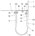
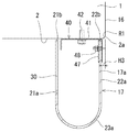
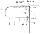
- FIG. 9 is a cross-sectional view of the outer hood taken along line FF in FIG. 2
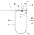
- FIG. 10 is a cross-sectional view taken along line GG in FIG. 2
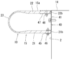
- FIG. 11 is a cross-sectional view taken along line HH in FIG. It is.
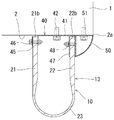
- the cross section is concave as shown in FIGS. 9 to 11 along the positions where the side hood part 13, the shoulder hood part 17, and the upper hood 15 of the right hood 10 are attached.
- the mounting plates 40 are arranged in series, and the board 41 is fixed to the end face of the vehicle body 1 by bolts 42.
- the right hood 10 is attached to the base end portions 21b and 22b of the base portions 21 and 22 with the mounting plate 40, the pressers 45 and 47, and the bolts 46 and 48, as shown in FIGS. It is attached to the car body.
- the notch 30 is formed in the shoulder hood portion 17 shown in FIG. 10 and the vehicle body mounting side of the notch 30 is opened. Therefore, the inner plate of the mounting plate 40 is not provided in the shoulder hood portion 17. Being slow.
- the outer hood 8 is fixed and attached to the end face 2 so that the inner base portions 21 and 21a and the outer base portions 22 and 22a protrude perpendicularly from the end face 2.
- the roof-side hood 11 has a cross-sectional shape (H′-H ′ line cross-sectional shape in FIG. 2), and a cross-sectional shape (HH line cross-sectional shape) of the upper hood 15 in the left and right side hoods 9 and 10.
- H′-H ′ line cross-sectional shape in FIG. 2 a cross-sectional shape of the upper hood 15 in the left and right side hoods 9 and 10.
- the roof edge 2 a of the end face 2 of the vehicle body 1 is formed between the tip of the upper hood 15 of the left hood 9 and the tip of the upper hood 15 of the right hood 10. It is located on the inner side along (the roof surface 14 of the vehicle body).
- the roof side hood 11 is formed of a flexible elastic material such as synthetic rubber.
- the attachment structure of the roof side hood 11 to the end face 2 of the vehicle body 1 is the same as the attachment structure shown in FIG. Therefore, the description of the mounting structure is omitted.
- the wife surface 5 of the other vehicle body 4 is located outside the inner hood 7 and along the outer peripheral portion of the wife surface 5 like the outer hood 8.
- the other outer hood 8 ⁇ / b> A is attached to face the outer hood 8.
- the other outer hood 8A is composed of left and right side hoods 9, 10 and a roof side hood 11, similar to the one outer hood 8.
- the left and right side hoods 9, 10 of the other outer hood 8A The hood 8 includes a side hood part 13, a shoulder hood part 17, and an upper hood part 15, and the cross-sectional shape and the mounting structure of the vehicle body 4 are the same as those of the one outer hood 8.
- the left and right side hoods 9 and 10 and the roof side hood 11 in the outer hood 8A are also formed of a flexible elastic material such as synthetic rubber as described above.
- one outer hood 8 and the other outer hood 8A are separated from each other, and the front portions 23 and 23a of one outer hood 8 and the tip of the other outer hood 8A are separated.
- the parts 23, 23 a are attached to the vehicle bodies 1, 4 so as to press each other at the approximate center between the vehicle bodies 1, 4.
- the side hood portion 13, the shoulder hood portion 17, the upper hood portion 15, and the roof side hood 11 have outer base portions 22, 22 a of the vehicle bodies 1, 4. Arranged by a predetermined distance M (see FIG. 11) from the edges 2a and 5a of the end faces 2 and 5 (outside surfaces of the vehicle bodies 1 and 4) to the inside of the end faces 2 and 5.
- the side hood part 13, the shoulder hood part 17, the upper hood part 15, and the outer side face 2 of the roof side hood 11 have edges 2a of the end faces 2, 5 as shown in FIGS.
- a curved member 50 is fixed by a bolt 51 so as to bulge outward from 5a toward the outer bases 22 and 22a.
- suppression of the radiation in the shoulder hood part 17 is performed by the non-hole-shaped outer base part 22a and the front part 23a.
- the noise emission (radiation in the direction of arrow K in FIG. 42) from the shoulder portion of the wife surface, which was generated in the conventional outer hoods 107 and 108 shown in FIGS. Can be suppressed. Further, by providing the upper hood 15 and the roof side hood 11, it is possible to suppress upward noise emission.
- the notch 30 is formed in the inner base portion 21a of the shoulder hood portion 17, the rigidity at the shoulder hood portion 17 becomes small and can be flexibly deformed. Therefore, when the outer hoods 8 and 8A are displaced in the pressed state, the shoulder hood portion 17 is easily deformed, the generated wrinkles are reduced and reduced, and the occurrence of cracks in the shoulder hood portion 17 can be reduced. .
- the thickness of the inner base portion 21a and the outer base portion 22a of the shoulder hood portion 17 is made thinner than the thickness of the inner base portion 21 and the outer base portion 22 of the side hood portion 13 and the upper hood portion 15, and the front portion 23a. Since the wall thickness of the shoulder hood 17 is also reduced, the rigidity of the shoulder hood portion 17 is further reduced and the flexibility is increased in combination with the formation of the notch 30, and the occurrence of the cracks can be further reduced.
- the rigidity in the vicinity of the shoulder hood portion 17 can be lowered, and the generation of wrinkles in the shoulder hood portion 17 can be further reduced.
- the inner base 21 a in the shoulder hood 17 is abnormally turned even if the auxiliary hole 32 is provided close to the notch 30. Prevent it from going up.
- the single notch 30 is formed in the shoulder hood portion 17, but the single cutout 30 is not formed as in the outer hood for a railway vehicle according to the second embodiment of the present invention.
- the shoulder hood portion 17 may be formed with a plurality of notches.
- Such a plurality of notches can also reduce the rigidity of the inner base portion 21a, that is, the shoulder hood portion 17, and exhibit the same operations and effects as described above.
- the notch 30 may be provided within the range of the shoulder hood portion in a range where the flexibility required for the shoulder hood portion 17 is obtained without being formed over the entire length of the shoulder hood portion 17. That is, the notch 30 may be provided in a desired range and part within the range of the shoulder hood part 17.
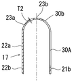
- FIG. 13 is a cross-sectional view of the shoulder hood portion of the outer hood for a railway vehicle according to the third embodiment of the present invention.
- the shoulder hood portion 17 is a modification of the notch 30 in the shoulder hood portion 17 of the first embodiment.
- the notch 30 is formed on the inner side which is the center side of the end face from the end surface 21c which is the attachment side to the vehicle body to a position including a part of the front portion 23a.
- the tip 30b of the notch 30 is set at a position that does not reach the vertex 23b.
- FIGS. 14 and 15 show a cross-sectional view of the shoulder hood portion of the outer hood according to the fourth embodiment of the present invention and a view seen from the inside.
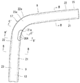
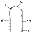
- FIGS. A hole 30A is formed. That is, in the inner base portion 21a of the shoulder hood portion 17, the base end portion 21b is left on the attachment side to the vehicle body, and a part of the inner base portion 21a is left on the front portion 23a side so as to penetrate in the inner and outer directions.
- a hole 30A is formed.
- 30b shows the tip of the hole 30A.
- FIG. 16 is a cross-sectional view of the shoulder hood of the outer hood according to the fifth embodiment of the present invention.
- the hole 30A in the fourth embodiment is formed up to a position including a part of the front portion 23a.
- the tip 30b of the hole 30A is set at a position that does not reach the apex 23b.
- the thickness T2 of the inner base portion 21a, the outer base portion 22a, and the tip portion 23a of the shoulder hood portion 17 is set to the thickness of the inner base portion 21 and the outer base portion 22 of the side hood portion 13 and upper hood portion 15.
- the shoulder hood portion 17 of the outer hood according to the sixth embodiment of the present invention shown in FIG. 17 has a lateral cross-sectional shape (cross section taken along the line CC in FIG. 4), which is shown in FIG.
- the same shape as the cross-sectional shape of the upper hood part 15 is used. That is, the thickness of the inner base portion 21a and the outer base portion 22a of the shoulder hood portion 17 is set to the same thickness as T1 shown in FIG.
- the thickness of the tip portion 23a is set to be greater than the thickness of the inner base portion 21a and the outer base portion 22a. Also, the thickness T2 shown in FIG. 5 is thin.
- the notch 30 as described above is formed in the inner base 21a at the same position as in the first embodiment and in the same shape.
- the notch 30 is formed in the inner base portion 21 a of the shoulder hood portion 17, so that the shoulder hood portion 17, that is, the inner side of the shoulder hood portion 17, compared to the side hood portion 13 and the upper hood portion 15.
- the rigidity of the base portion 21a is small and the flexibility is large, and the same functions and effects as those of the first embodiment can be exhibited.
- FIG. 18 is a cross-sectional view of the shoulder hood portion of the outer hood according to the seventh embodiment of the present invention. This is a modification of the notch 30 in the shoulder hood portion 17 of the sixth embodiment.
- a notch 30 is formed on the inner side which is the center side of the surface from the end surface 21c which is the attachment side to the vehicle body to a position including a part of the front portion 23a.
- the tip 30b of the notch 30 is set at a position that does not reach the vertex 23b.
- FIG. 19 shows a cross-sectional view of the shoulder hood portion of the outer hood according to the eighth embodiment of the present invention, in which a hole 30A is formed instead of the notch 30 in the shoulder hood portion 17 of the sixth and seventh embodiments. is there. That is, in the inner base portion 21a of the shoulder hood portion 17, the base end portion 21b is left on the attachment side to the vehicle body, and the hole 30A is formed by leaving a part of the inner base portion 21a on the front portion 23a side.
- FIG. 20 shows a cross-sectional view of the shoulder hood portion of the outer hood according to the ninth embodiment of the present invention, in which the hole 30A in the eighth embodiment is formed up to a position including a part of the tip portion 23a.
- the tip 30b of the hole 30A is set at a position that does not reach the apex 23b.
- FIGS. 21, 23 and 24 show an outer hood for a railway vehicle according to a tenth embodiment of the present invention.
- the side hood portion 13 and the upper hood portion 15 are shown in FIG. 22, and the inner base portion 21 and the outer base portion 22 are shown in FIG.
- the thick portion is formed with the tip portion 23 being thin
- the shoulder hood portion 17 is provided with the inner base portion 21a, the outer base portion 22a, and the tip portion 23a as shown in FIG.
- the hole 30A is formed as a thin wall as in the first embodiment, and as shown in FIGS. 21, 23 and 24, a part of the inner base portion 21a of the shoulder hood portion 17 and the inner base portion 21 of the side hood portion 13 are formed.
- a part of the tip part 23a of the shoulder hood part 17 and a part of the tip part 23 of the side hood part 13 are formed in the holes including the parts as described above.
- the roof-side hood 11 is provided. However, like the outer hood for a railway vehicle according to the eleventh embodiment of the present invention shown in FIGS. 25, 26, 27A, and 27B, the roof-side hood 11 is used.
- the outer hood may be constituted by only the left hood 9 and the right hood 10 without providing the hood.
- the plate thickness, shape, material, and mounting structure of the left hood 9 and right hood 10 of the eleventh embodiment are the same as those of the first to tenth embodiments.
- the same reference numerals as those described above are attached and description thereof is omitted.
- a notch 30 or a hole 30A similar to the above is formed in the shoulder hood portion 17.
- the present embodiment 11 since the roof side hood 11 does not exist, noise is generated from the opened upper portion 400 in FIG. Due to the presence of the portion 13, the shoulder hood portion 17, and the upper hood portion 15, it is possible to suppress the noise of the connecting portion between the vehicle bodies from being radiated sideways and obliquely upward.
- this embodiment 11 is also effective as a noise countermeasure.
- the roof hood 11 is not provided, and the upper hood portion 15 is extended on the upper end side of the shoulder hood portion 17, but in the outer hood for a railway vehicle according to the embodiment 12 of the present invention,
- the outer hood may not be provided with the upper hood portion 15.
- the upper hood part 15 from the ZZ line may be eliminated, and only the side hood part 13 and the shoulder hood part 17 may be formed.
- Example 12 Since other structures are the same as those of the eleventh embodiment, description thereof is omitted. Also in the present Example 12, an effective sound insulation effect can be exhibited, and the same operations and effects as those of Example 11 can be exhibited.
- FIGS. 28 to 33 show an outer hood for a railway vehicle according to a thirteenth embodiment of the present invention.
- the bending member 50 in the first embodiment is eliminated, and the left hood 9, the right hood 10 and the roof side of the first embodiment.
- Each of the outer surfaces of the hood 11 (strictly speaking, the outer surface of the mounting plate 40) is flush with the left side edge 2 a of the vehicle body face 2, the right side edge 2 a of the body face 2, and the roof side edge 2 a of the body face 2. It arranges so that it may be located.
- the left hood 9 is a hood similar to the left hood 9 of the first embodiment, and includes a side hood portion 13, a shoulder hood portion 17, and an upper hood portion 15 as described above.
- a right hood 10 is a hood similar to the right hood 10 of the first embodiment, and includes a side hood portion 13, a shoulder hood portion 17, and an upper hood portion 15 as described above.
- left and right hoods 9 and 10 are the same as the left and right hoods 9 and 10 of the first embodiment except that the front shape of the upper hood portions 15 and 15 is slightly different from that of the first embodiment.
- the left and right side hood parts 13 and 13 of the thirteenth embodiment are arranged so that the outer surface 13a thereof is on the same plane as the left and right side surfaces 12 of the vehicle body as shown in FIG. 15 is arranged so that its outer surface 15a is flush with the roof surface 14 of the vehicle body as shown in FIG. 33, and the shoulder hood portions 17 and 17 have their outer surfaces 17a as shown in FIG.
- the vehicle body is disposed on the same plane as the shoulder surface 16 of the vehicle body.
- the roof side hood 11 is a hood similar to the roof side hood 11 of the first embodiment, and the front side shape of the roof side hood 11 of the thirteenth embodiment is slightly different from that of the first embodiment. Others are the same as the roof top 11 of the first embodiment.
- roof side hood 11 of the thirteenth embodiment is arranged so that its outer surface 11a is located on the same plane as the roof surface 14 of the vehicle body as in FIG.
- FIG. 31 shows the cross section (FF line cross section) structure of the side hood part 13 in Example 13, and FIG. 32 shows the cross section (GG line cross section) structure of the shoulder hood part 17.
- FIG. 33 shows the structure of 15 cross sections (HH line cross section) and the roof side hood 11 cross section (H′-H ′ line cross section).
- Example 14 the same operation and effect as Example 13 can be exhibited except for the bending member 50.
- FIGS. 36 to 39 show an outer hood for a railway vehicle according to a fifteenth embodiment of the present invention.
- the curved hood 50 in the first embodiment is eliminated, and the left hood 9, the right hood 10 and the roof side of the first embodiment.
- the hoods 11 are arranged such that their outer surfaces are close to the inside on the left side edge 2a of the body surface 2, the right side edge 2a of the body surface 2, and the roof side edge 2a of the body surface 2. .
- the left hood 9 is a hood similar to the left hood 9 of the first embodiment, and has a side hood portion 13, a shoulder hood portion 17, and an upper hood portion 15 as described above.
- the right hood portion 10 is a hood similar to the right hood 10 of the first embodiment, and has a side hood portion 13, a shoulder hood portion 17, and an upper hood portion 15 as described above.
- left and right hoods 9 and 10 are the same as the left and right hoods 9 and 10 of the first embodiment except that the front shape of the upper hood portions 15 and 15 is slightly different from that of the first embodiment.
- the outer surface 13a is located in the inner end of the curved part R1 formed in the right and left side edge 2a of the end face 2 as shown in FIG. That is, in other words, the outer surface 13a is disposed at a position entering the inside by a distance H3 from the left and right side surfaces 12 of the vehicle body to the inner end of the curved portion R1.
- the upper hood portions 15 and 15 are arranged so that the outer surface 15a thereof is located at the inner end of the curved portion R1 formed on the roof side edge 2a of the end surface 2, as shown in FIG.
- the vehicle is disposed at a position that is located inside by a distance H3 from the roof surface 14 of the vehicle body to the inner end of the curved portion R1.
- the shoulder hood portions 17 and 17 have an outer surface 17a positioned at the inner end of the curved portion R1 formed on the shoulder edge 2a of the end face 2, that is, the outer surface 17a is a vehicle body. It is arranged at a position entering the inside by a distance H3 from the shoulder surface 16 to the inner end of the curved portion R1.
- the roof-side hood 11 is a hood similar to the roof-side hood 11 of the first embodiment, and the front-side shape of the roof-side hood 11 of the fifth embodiment is slightly different from that of the first embodiment. Others are the same as the roof top 11 of the first embodiment.
- roof side hood 11 of the fifteenth embodiment is arranged at a position where the outer surface 11a is inward by H3 from the roof surface 14 of the vehicle body as in FIG.
- FIG. 37 shows the cross-sectional structure of the side hood part 13 in Example 15
- FIG. 38 shows the cross-sectional structure of the shoulder hood part 17, and the cross-sectional structure of the upper hood part 15 and the cross-sectional structure of the roof side hood 11 are shown. It shows in FIG.
- the outer hood can be attached to avoid the curved surface portion when the edge portion of the wife surface is formed as a curved surface as shown in FIGS.
- FIG. 40 shows an outer hood for a railway vehicle according to a sixteenth embodiment of the present invention.
- This sixteenth embodiment is the same as the fifteenth embodiment except that the roof-side hood 11 is removed. Since other structures are the same as those of the fifteenth embodiment, the same parts as those described above are denoted by the same reference numerals as those described above, and the description thereof is omitted.
- Example 16 Also in the present Example 16, the same operation and effect as the Example 15 can be exhibited.
- a notch or a hole is formed in each shoulder hood portion of the outer hood 8 on the one vehicle body 1 side and the outer hood 8A of the other vehicle body 4, but the railway vehicle according to the seventeenth embodiment of the present invention.
- this notch or hole may be provided in the outer hood 8 on the one vehicle body 1 side and not in the outer hood 8A of the other vehicle body 4.
Landscapes
- Engineering & Computer Science (AREA)
- Life Sciences & Earth Sciences (AREA)
- Wood Science & Technology (AREA)
- Mechanical Engineering (AREA)
- Superstructure Of Vehicle (AREA)
- Body Structure For Vehicles (AREA)
Abstract
車体の妻面に付設される鉄道車両用外幌の構成において、車体間の連結空間より発生する騒音低減を図り、外幌の耐久性を高めるため、妻面の側部に沿った側幌部13と、妻面の肩部において湾曲した肩幌部17とを備え、これらを連設するとともにこれらを弾性材で形成し、側幌部13と肩幌部17の横断面形状が、内側基部21、21aと外側基部22、22aとこれらの先を連結した先部とでU字状に形成され、肩幌部17における内側基部21aに少なくとも一つの穴30A又は切欠き30が形成されていることを特徴とする鉄道車両用外幌の構造。
Description
本発明は鉄道車両用外幌の構造に関する。
従来、鉄道車両における車体間の連結部の空間に、渡り通路を形成する内幌を設けるとともに、該内幌の両側の外側に、車両の走行時に発生する騒音が車体間より車体の外部へ放射されることを抑制する外幌を設ける構造が知られている。
この構造として従来、例えば、図41乃至図43に示すように、連結された一方の車体101の妻面102と他方の車体103の妻面104間に通路105を構成する内幌106を架設し、図42の該内幌106の水平方向での両外側に、内幌106と離間して、一方の車体101の妻面102から断面形状をU字状に突設した可撓性を有する一方の外幌107と、他方の車体103の妻面104から断面形状をU字状に突設した可撓性を有する他方の外幌108を設け、これらの先部を図41、図43に示すように、相互に対向接触させている。
そして、この外幌107は、図42に示すように、妻面102において車体101の両側面である略直立部に沿った範囲、すなわち、妻面の側部111の範囲のみに設けられ、妻面102の肩部(車体の肩部)112と屋根部113の範囲の部分には設けられていない。これは、図示されていないが、他方の外幌108でも同様である。
このような外幌107、108においては、連結部空間114内から車体の水平方向への騒音の放射は抑制されるが、連結部空間114内からの騒音が肩部112の開放部115を通じて矢印Kのように外部へ放射され車外へ影響を与える。
また、屋根側の開放部116からも矢印Lのように騒音が放射され、これらの騒音の放射を抑制することが好ましい。
そこで、従来、前記の外幌107、108を、車体の妻面における左右両側に配置するのみではなく、図44に示すように、略垂直の側幌部200の上部を延長して、前記妻面(車体)の肩部112において、外側へ膨出する湾曲状の肩幌部201を延設し、かつ、その肩幌部201の端部からさらに妻面(車体)の屋根縁に沿った屋根側幌部202を延設して前記妻面の肩部112の開放部115及び屋根側の開放部116からの騒音低減を図るものが特許文献1に知られている。
しかし、前記図44に示す外幌は、図45に示すように、横断面形状がU字状で、かつ、その両側基部203、204を剛性のある厚肉で形成し、先部205を可撓性を高めるために両側基部203、204よりも薄肉に形成されており、このような断面形状の外幌を前記図44に示すような肩幌部201において使用すると、次のような問題が生じる。
前記の外幌の肩幌部201は、側幌部200と屋根側幌部202を一体的に連続する湾曲した形状となることから柔軟に変形し難くなる。
そのため、この湾曲する肩幌部201において、剛性が高い厚肉の両側基部203、204を有する外幌を使用した場合には、肩幌部201における内側辺300に大きなしわが多数発生し、かつ、該内側辺300の剛性が大きいことから、対向する外幌と擦れ合うと、この肩幌内側部で亀裂が生じやすく、この亀裂が生じると、該部を起点として亀裂が広がり、外幌の耐久性が低減する虞がある。
そこで、本発明は、この湾曲状の肩幌部の耐久性を高める構造にして、耐久性の良い鉄道車両用外幌の構造を提供することを目的とするものである。
前記の課題を解決するために請求項1記載の本願発明は、車体の妻面に付設され、横断面において内側基部と外側基部とこれらの先を連結した先部とで構成される外幌であって、妻面の側縁に沿った側幌部と妻面の肩部において湾曲した肩幌部とを連設した外幌において、前記肩幌部の内側に少なくとも一つの穴又は切欠きを形成したことを特徴とするものである。
請求項2記載の本願発明は、車体の妻面に付設される外幌において、妻面の側縁に沿った側幌部と、妻面の肩部において湾曲した肩幌部とを備え、これらを連設するとともに弾性材で形成し、前記側幌部と肩幌部の横断面形状が、内側基部と外側基部とこれらの先を連結した先部とでU字状に形成され、前記肩幌部における内側基部に少なくとも一つの穴又は切欠きが形成されていることを特徴とするものである。
請求項3記載の本願発明は、請求項1又は2記載の発明において、前記側幌部の先部の肉厚を、該側幌部の内側基部と外側基部の肉厚よりも薄く形成し、前記肩幌部における内側基部と外側基部と先部の肉厚を、前記側幌部における内側基部と外側基部の肉厚よりも薄く形成したことを特徴とするものである。
請求項4記載の本願発明は、請求項1又は2記載の発明において、前記側幌部の先部の肉厚を、該側幌部の内側基部と外側基部の肉厚よりも薄く形成し、前記肩幌部の先部の肉厚を前記側幌部の先部の肉厚と同等にし、前記肩幌部の内側基部と外側基部の肉厚を、前記側幌部の内側基部と外側基部の肉厚と同等にしたことを特徴とするものである。
請求項5記載の本願発明は、請求項1乃至4のいずれか1項に記載の発明において、前記穴又は切欠きを、前記肩幌部において1個又は複数個設けたことを特徴とするものである。
請求項6記載の本願発明は、請求項1乃至5のいずれか1項に記載の発明において、前記肩幌部における前記側幌部と反対側の上部に、妻面の屋根縁に沿った上幌部を延設し、該上幌部の横断面形状を、前記側幌部の横断面形状と同等に形成したことを特徴とするものである。
請求項7記載の本願発明は、請求項6記載の発明において、前記上幌部における前記肩幌部と反対の側に、妻面の屋根縁に沿った屋根側幌を配置するとともに該屋根側幌の横断面形状を前記側幌部の横断面形状と同等に形成して、該屋根側幌と前記上幌部とで車両の連結部空間の上部全体を覆うようにしたことを特徴とするものである。
請求項1及び2記載の本願発明によれば、肩幌部の内側に穴又は切欠きを形成したことで、肩幌部の変形が容易になり、該部で発生するしわを少なくするとともに小さくし、亀裂の発生を低減して外幌の耐久性を高めることができる。
請求項3記載の本願発明によれば、肩幌部における外側基部と内側基部と先部を薄肉に形成して柔軟性を高め、かつ、内側基部に穴又は切欠きを形成したので、肩幌部の柔軟性が極めて高くなり、肩幌部の変形を容易にして外幌の耐久性を高めることができる。
請求項4記載の本願発明によれば、肩幌部の内側基部の肉厚が前記請求項3の発明における内側基部の肉厚よりも厚いが、この内側基部に穴又は切欠きを形成したことにより、肩幌部の変形が容易になり、前記請求項1又は2の効果を発揮できる。
請求項5記載の本願発明においても前記と同様な効果を発揮できる。
請求項6記載の本願発明においては、上幌部を設けたものにおいても前記と同様の効果を発揮できる。
請求項6記載の本願発明においては、上幌部を設けたものにおいても前記と同様の効果を発揮できる。
請求項7記載の本願発明においては、屋根側幌を設けたものにおいても前記と同様の効果を発揮できる。
本発明による鉄道車両用外幌を実施するための形態を、図1乃至図40に基づいて説明する。
図1乃至図12は本発明による外幌の実施例1を示す。
図1乃至図3は本発明の外幌を鉄道車両の車体の妻面に付設した状態を示し、図1は車体間の連結部の側面図、図2は図1のA-A線で妻面側から見た連結部の正面図、図3はその平面図である。
図1乃至図3は本発明の外幌を鉄道車両の車体の妻面に付設した状態を示し、図1は車体間の連結部の側面図、図2は図1のA-A線で妻面側から見た連結部の正面図、図3はその平面図である。
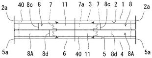
図3に示されるように、連結された一方の車体1の妻面2の出入口3と、他方の車体4の妻面5の出入口6との間には、蛇腹状の内幌7が架設され、該内幌7内に渡り通路7aが形成されている。
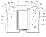
また、図2に示されるように、前記一方の車体1の妻面2には、前記内幌7の外側であって、妻面2の外周部に位置する一方の外幌8が付設されている。該一方の外幌8は、図2において左側幌9と右側幌10と屋根側幌11の3部材に分割して構成されている。
前記左側幌9は、図2の妻面2の左側縁2a(車体の左側面12)に沿って内側に位置し略垂直方向に立上がるように形成された側幌部13と、妻面2の屋根縁2a(車体の屋根面14)に沿って内側に位置し、略水平方向で、車体妻面の内側(妻面の中央X-X)へ向うように形成された上幌部15と、前記側幌部13と上幌部15との間を、妻面2の肩部18において車体の肩面16より内側に位置して外方へ膨出するように湾曲して結合した肩幌部17とからなり、これら側幌部13と上幌部15と肩幌部17は継がって形成されている。
すなわち、略垂直方向に立上がる側幌部13の上部に、妻面の中央側に中心O(図4参照)を有し、外側へ膨出するように湾曲した肩幌部17が延設され、更に、該肩幌部17の上部に略水平方向で妻面の内側(妻面の中央X-X)方向へ向うように上幌部15が延設されている。なお、実施例では、車体の肩面16が曲面で形成され、この曲面に沿って前記外幌の肩幌部17が湾曲に形成されている。
更に、左側幌9は、前記側幌部13と上幌部15と肩幌部17を、該各部が後述するU字状の横断面形状で、かつ、図2に示す一連の形状で、型成形により一体成形されているかもしくは、平板をU字状に折り曲げて形成した前記側幌部13と上幌部15と、U字状の横断面形状に型成形された肩幌部17を図2に示すような形状に継なげて形成されている。この左側幌9は、合成ゴム等の可撓性を有する弾性材で形成されている。
前記右側幌10は、図2に示すように、前記左側幌9に対して、車体1の妻面2の中央X-Xを中心として左右対称の形状に形成され、かつ、その構造は前記左側幌9と同様である。そのため、右側幌10については、前記左側幌9と同一部分に前記と同一符号を付して、その説明を省略する。なお、図の実施例では、右側幌10における上部幌15の水平方向の長さは、左側幌9の上部幌15よりも若干短く形成されている。
前記屋根側幌11は、前記左側幌9の上幌部15の先端と、右側幌10の上幌部15の先端との間に、図2に示すように配置されている。
次に、前記左側幌9の断面形状について図4乃至図8により詳述する。
図4に示す左側幌9の側幌部13の横断面形状(B-B線断面)は、図5に示すように、基端側に開口部20を有するU字状に形成されている。すなわち、所定の間隔を有して平行に配置した板状の内側基部21と板状の外側基部22と、該両基部21、22の先を連結する先細状(図の実施例では略半円状)の先部23とからなる。また、両基部21、22は、これを妻面に付設した際に、その妻面からの突出状態を保持するために剛性が大きく可撓性の小さい厚肉T1に形成され、先部23は、両基部21、22より薄肉T2に形成され、該先部23が両基部21、22に比べて剛性が小さく可撓性を大きくして形成されている。また、基部21、22から先部23への連結部24は、肉厚が漸減するように形成されている。
図4に示す左側幌9の側幌部13の横断面形状(B-B線断面)は、図5に示すように、基端側に開口部20を有するU字状に形成されている。すなわち、所定の間隔を有して平行に配置した板状の内側基部21と板状の外側基部22と、該両基部21、22の先を連結する先細状(図の実施例では略半円状)の先部23とからなる。また、両基部21、22は、これを妻面に付設した際に、その妻面からの突出状態を保持するために剛性が大きく可撓性の小さい厚肉T1に形成され、先部23は、両基部21、22より薄肉T2に形成され、該先部23が両基部21、22に比べて剛性が小さく可撓性を大きくして形成されている。また、基部21、22から先部23への連結部24は、肉厚が漸減するように形成されている。
前記上幌部15の横断面形状(図4のB-B線断面)は、前記側幌部13の図5に示す横断面形状(図4のB-B線断面)と同様に、妻面に固定される内側基部21と外側基部22とこれらの先を連結した先部23とでU字状に形成した形状であり、その肉厚も同様に形成されているが、これらの肉厚、形状等の寸法は妻面の構造で異なることもある。
前記肩幌部17の横断面形状(図4のC-C線断面)は、図6に示すように、基端側に開口部20を有するU字状に形成され、その外周形状は前記図5に示す側幌部13の外周形状と同一形状である。また、その板状の内側基部21aと板状の外側基部22aの肉厚は、前記図5に示す側幌部13の先部23の肉厚T2と同等に形成され、更に、その先部23aの肉厚は、前記図5の先部23の肉厚T2と同等に形成されている。すなわち、肩幌部17における内側基部21aと外側基部22aと先部23aの肉厚T2は前記側幌部13、上幌部15の内側基部21と外側基部22の肉厚T1よりも薄肉に形成されている。したがって、肩幌部17における図4に示す湾曲部R全体が薄肉に形成され、側幌部13、上幌部15よりも可撓性が大きくなっている。
また、肩幌部17における薄肉部から側幌部13及び上部幌15のへの連結部25の基部の肉厚は、図8に示すように、漸増している。
前記肩幌部17における内側基部21aには図6及び図7に示すように、内側基部21aにおける内外方向に貫通する切欠き30が形成されている。
該切欠き30は、肩幌部17における内側基部21aにおいて、図7に示すように、車体への取付側、すなわち基端部21bの端面21c側に開口部30aを有するように、内側基部21aの一部を切り欠いた1個の切欠き30で形成されている。該切欠き30における外幌の軸方向Y-Yに沿う長さL1と高さH1は所望に設定されるが、高さH1は図に示す実施例では図6の内側基部21aの高さH2より若干短く設定されている。更に、該切欠き30の角部30cは曲面で形成されている。
更に、前記上幌部15における内側基部21には、前記切欠き30に近接して1個の補助穴32が形成されている。該補助穴32は、内側基部21の内外方向に貫通する穴で形成され、かつ、内側基端部21の基端部21bの端面21cには開口していない。また、該補助穴32は、前記切欠き30よりも小さい穴で形成され、その先端32aは切欠き30の先端30bと略同一高さに設定されている。
したがって、前記切欠き30と補助穴32との間には第1連結片33が有り、補助穴32の下部には内側基部21からなる第2連結片34が存在する。
なお、肩幌部17における外側基部22aには、前記の切欠き30及び補助穴32は形成されていない。
また、前記右側幌10の側幌部13、肩幌部17、上部幌15も前記左側幌9の側幌部13、肩幌部17、上部幌15と同様の構造であるため、その説明は省略する。
次に、車体1の妻面2に対する前記左側幌9と右側幌10の取付構造を図9乃至図11により説明する。
なお、この取付構造を図2に示す外幌の右側幌10により説明する。
図9は図2におけるF-F線に沿った外幌の断面図、図10は図2におけるG-G線に沿った断面図、図11は図2におけるH-H線に沿った断面図である。
図9は図2におけるF-F線に沿った外幌の断面図、図10は図2におけるG-G線に沿った断面図、図11は図2におけるH-H線に沿った断面図である。
前記車体1の妻面2には、前記右側幌10の側幌部13、肩幌部17、上部幌15を取付ける位置に沿って、図9乃至図11に示すような、横断面が凹状の取付板40が一連に配置され、その基板41がボルト42により車体1の妻面に固定されている。
そして、右側幌10の取付けは、図9乃至図11に示すように、両基部21、22の基端部21b、22bにおいて、前記取付板40、押え金45、47、及びボルト46、48で車体に取付けられている。なお、図10に示す肩幌部17には前記の切欠き30が形成され、該切欠き30の車体取付側が開口されているため、該肩幌部17においては取付板40の内側板が欠徐されている。
なお、図2の左側幌9の車体1の妻面2に対する取付構造は、前記右側幌10の取付構造と同様であるため、その説明は省略する。
上記の取付けにより、外幌8は、その内側基部21、21aと外側基部22、22aが妻面2より垂直に突出するように妻面2に固定されて取付けられる。
次に、前記屋根側幌11について説明する。
該屋根側幌11は、その横断面形状(図2のH’―H’線断面形状)が、前記左右側幌9、10における上部幌15の横断面形状(H-H線断面形状)と同様に形成され、前記左側幌9の上幌部15の先端部と右側幌10の上部幌15の先端部との間において、図2に示すように、車体1の妻面2の屋根縁2a(車体の屋根面14)に沿って内側に位置して配置されている。更に、該屋根側幌11は、前記左右側幌9、10と同様に、合成ゴム等の可撓性を有する弾性材で形成されている。
該屋根側幌11は、その横断面形状(図2のH’―H’線断面形状)が、前記左右側幌9、10における上部幌15の横断面形状(H-H線断面形状)と同様に形成され、前記左側幌9の上幌部15の先端部と右側幌10の上部幌15の先端部との間において、図2に示すように、車体1の妻面2の屋根縁2a(車体の屋根面14)に沿って内側に位置して配置されている。更に、該屋根側幌11は、前記左右側幌9、10と同様に、合成ゴム等の可撓性を有する弾性材で形成されている。
該屋根側幌11の車体1の妻面2に対する取付構造は、前記図11に示す取付構造と同様である。そのため、その取付構造の説明は省略する。
前記他方の車体4の妻面5には、図1、図3及び図12Bに示すように、前記内幌7の外側であって、前記外幌8と同様に妻面5の外周部に沿って、かつ、前記外幌8と対向して他方の外幌8Aが付設されている。
該他方の外幌8Aは、前記一方の外幌8と同様に左右側幌9、10と屋根側幌11とからなり、該他方の外幌8Aの左右側幌9、10は前記一方の外幌8と同様の側幌部13と肩幌部17と上幌部15とからなり、これらの横断面形状及び車体4との取付構造は前記一方の外幌8と同様である。更に、この外幌8Aにおける左右側幌9、10と屋根側幌11も前記と同様に合成ゴム等の可撓性を有する弾性材で形成されている。
そして、一方の外幌8と他方の外幌8Aが、図1、図3に示すように、相互に分割されて、一方の外幌8の先部23、23aと他方の外幌8Aの先部23、23aが、両車体1、4間の略中央で相互に押し付け合うように車体1、4に付設されている。
なお、前記一方の外幌8における屋根側幌11と上幌部15との接合部8cと他方の外幌8Aにおける屋根側幌11と上幌部15との接合部8dは、図3に示すように、左右方向に齟齬して配置されている。
前記側幌部13、肩幌部17、上幌部15、屋根側幌11は、図1、図3及び図9乃至図11に示すように、その外側基部22、22aが車体1、4の妻面2、5の縁2a、5a(車体1、4の外面)より妻面2、5の内側へ所定の距離M偏位(図11参照)して配置されている。
そして、前記側幌部13、肩幌部17、上幌部15、屋根側幌11の外側の妻面2には、図9乃至図11に示すように、妻面2、5の縁2a、5aから外側基部22、22aに向って外側へ膨出するように湾曲した湾曲部材50がボルト51により固設されている。
前記実施例1においては、前記の構成により、次のような作用、効果を発揮する。
両車体1、4に付設された両外幌8、8Aの先部が相互に接触することにより、両車体1、4間の連結部空間の外周部が両外幌8、8Aで被覆され、車両走行中における連結部空間内の騒音の側方への放射は側幌部13で抑制され、車体肩部からの斜め上方への放射は肩幌部17で抑制され、上方への放射は上幌部15及び屋根側幌11で抑制される。
両車体1、4に付設された両外幌8、8Aの先部が相互に接触することにより、両車体1、4間の連結部空間の外周部が両外幌8、8Aで被覆され、車両走行中における連結部空間内の騒音の側方への放射は側幌部13で抑制され、車体肩部からの斜め上方への放射は肩幌部17で抑制され、上方への放射は上幌部15及び屋根側幌11で抑制される。
なお、肩幌部17での放射の抑制は、その無穴状の外側基部22aと先部23aで行われる。
したがって、本実施例1においては、前記図41乃至図43に示す従来の外幌107、108において発生していた妻面の肩部からの騒音の放射(図42の矢印K方向の放射)を抑制できる。また、上部幌15及び屋根側幌11を設けたことにより、上方への騒音の放射を抑制できる。
次に、車両走行中において、両外幌8、8Aが押し付けあった状態で相対的に変位すると、側幌部13と上幌部15及び屋根側幌11は、これらが略直線状であるため、内側又は外側へ容易に変位し、しわの発生が少なく亀裂の発生も少ない。
また、肩幌部17においては、その内側基部21aに切欠き30を形成したので、肩幌部17での剛性が小さくなり、柔軟に変形できる。そのため、両外幌8、8Aの押付け状態での変位に際して、該肩幌部17が容易に変形し、発生するしわが少なくなるとともに小さくなり、該肩幌部17での亀裂の発生を低減できる。
更に、該肩幌部17の内側基部21aと外側基部22aの肉厚を、側幌部13、上幌部15の内側基部21と外側基部22の肉厚よりも薄くし、かつ、先部23aの肉厚も薄くしたので、前記切欠き30の形成と相まって、さらに、肩幌部17の剛性が小さく、柔軟性が高くなり、前記の亀裂の発生を一層低減することができる。
また、補助穴32を形成したことにより、肩幌部17の近傍の剛性を低くして、肩幌部17のしわの発生をより低減することができる。
また、切欠き30と補助穴32との間に第1連結片33が存在するので、切欠き30に補助穴32を近接して設けても、肩幌部17における内側基部21aが異常にめくり上がることを防止する。
前記実施例1では、切欠き30を肩幌部17において1個で形成したが、本発明の実施例2による鉄道車両用外幌のように、この切欠き30を1個で形成することなく、肩幌部17において複数の切欠きで形成してもよい。
このような複数の切欠きによっても内側基部21a、すなわち、肩幌部17の剛性を低減し、前記と同様の作用、効果を発揮させることができる。
更に、前記切欠き30は、肩幌部17の全長にわたって形成することなく、肩幌部の範囲内において、肩幌部17に必要な柔軟性が得られる範囲に設けてもよい。すなわち、切欠き30は、肩幌部17の範囲内において所望の範囲、部分に設けても良い。
図13は本発明の実施例3による鉄道車両用外幌の肩幌部における横断面図を示すもので、前記実施例1の肩幌部17における切欠き30の変形例で、肩幌部17において、妻面の中心側である内側に、切欠き30を、車体への取付側である端面21cから先部23aの一部を含んだ位置まで形成したものである。図の実施例3では、切欠き30の先端30bを、前記頂点23bに達しない位置に設定している。
その他の構造は前記実施例1又は実施例2と同様である。
本実施例3においても前記実施例と同様の効果を発揮できる。
本実施例3においても前記実施例と同様の効果を発揮できる。
図14及び図15は本発明の実施例4による外幌の肩幌部における横断面図及び内側から見た図を示すもので、前記実施例1の肩幌部17における切欠き30の代りに穴30Aを形成したものである。すなわち、前記肩幌部17における内側基部21aにおいて、その車体への取付側に基端部21bを残し、先部23a側に内側基部21aの一部を残して内側基部21aにおける内外方向に貫通する穴30Aを形成したものである。30bは、穴30Aの先端を示す。
その他の構造は前記実施例と同様である。
本実施例4においても前記実施例と同様の効果を発揮できる。
本実施例4においても前記実施例と同様の効果を発揮できる。
なお、前記穴30Aは肩幌部17において1個で形成したが、複数個で形成してもよい。
図16は本発明の実施例5による外幌の肩幌部における横断面図を示すもので、前記実施例4における穴30Aを、先部23aの一部を含む位置まで形成したもので、図の実施例5では、穴30Aの先端30bを、前記頂点23bに達しない位置に設定している。
その他の構造は前記実施例4と同様である。
本実施例5においても前記実施例と同様の効果を発揮できる。
本実施例5においても前記実施例と同様の効果を発揮できる。
前記実施例1乃至5においては、肩幌部17における内側基部21aと外側基部22aと先部23aの肉厚T2を、側幌部13、上幌部15の内側基部21と外側基部22の肉厚T1よりも薄く形成したが、図17に示す本発明の実施例6による外幌の肩幌部17は、その横断面形状(図4のC-C線断面)を、前記側幌部13、上幌部15の横断面形状と同一形状としたものである。すなわち、肩幌部17の内側基部21aと外側基部22aの肉厚を前記図5に示すT1と同様の肉厚とし、先部23aの肉厚を、内側基部21aと外側基部22aの肉厚よりも薄い前記図5に示すT2としたものである。そして、該内側基部21aに前記のような切欠き30を前記実施例1と同様の位置に同様な形状で形成したものである。
その他の構造は、前記実施例1又は2と同様である。
本実施例6においても、肩幌部17の内側基部21aに切欠き30を形成したことにより、側幌部13、上幌部15に比べて肩幌部17、すなわち、肩幌部17の内側基部21aの剛性が小さく、柔軟性が大きくなり、前記実施例1と同様の作用、効果を発揮することができる。
本実施例6においても、肩幌部17の内側基部21aに切欠き30を形成したことにより、側幌部13、上幌部15に比べて肩幌部17、すなわち、肩幌部17の内側基部21aの剛性が小さく、柔軟性が大きくなり、前記実施例1と同様の作用、効果を発揮することができる。
図18は本発明の実施例7による外幌の肩幌部における横断面図を示すもので、前記実施例6の肩幌部17における切欠き30の変形例で、肩幌部17において、妻面の中心側である内側に、車体への取付側である端面21cから先部23aの一部を含んだ位置まで切欠き30を形成したものである。図の実施例では、切欠き30の先端30bを前記頂点23bに達しない位置に設定している。
その他の構造は前記実施例6と同様である。
本実施例7においても前記実施例と同様の効果を発揮できる。
本実施例7においても前記実施例と同様の効果を発揮できる。
図19は本発明の実施例8による外幌の肩幌部における横断面図を示すもので、前記実施例6、7の肩幌部17における切欠き30の代わりに穴30Aを形成したものである。すなわち、前記肩幌部17における内側基部21aにおいて、その車体への取付側に基端部21bを残し、先部23a側に内側基部21aの一部を残して穴30Aを形成したものである。
その他の構造は前記実施例6と同様である。
本実施例8においても前記実施例と同様の効果を発揮できる。
本実施例8においても前記実施例と同様の効果を発揮できる。
図20は本発明の実施例9による外幌の肩幌部における横断面図を示すもので、前記実施例8における穴30Aを、先部23aの一部を含む位置まで形成したものである。図の実施例9では穴30Aの先端30bを、前記頂点23bに達しない位置に設定している。
その他の構造は前記実施例8と同様である。
本実施例9においても前記実施例と同様の効果を発揮できる。
本実施例9においても前記実施例と同様の効果を発揮できる。
図21乃至図24は本発明の実施例10による鉄道車両用外幌を示すもので、側幌部13と上幌部15を、図22に示すように、その内側基部21と外側基部22を前記の実施例1のように厚肉とし、先部23を薄肉として形成し、前記肩幌部17を、図24に示すように、その内側基部21aと外側基部22aと先部23aを前記の実施例1のように薄肉として形成し、穴30Aを、図21、図23、図24に示すように、肩幌部17の内側基部21aの一部と、側幌部13の内側基部21の一部にわたり、かつ、肩幌部17の先部23aと側幌部13の先部23のそれぞれの一部を前記のように含む穴に形成したものである。
その他の構造は前記実施例と同様である。
本実施例10においても前記実施例と同様の効果を発揮できる。
本実施例10においても前記実施例と同様の効果を発揮できる。
前記実施例1乃至10では屋根側幌11を設けたが、図25、図26、図27A、図27Bに示す本発明の実施例11による鉄道車両用外幌のように、前記屋根側幌11を設けず、前記左側幌9及び右側幌10のみで外幌を構成しても良い。
なお、本実施例11の左側幌9及び右側幌10の板厚、形状、材質、妻面への取付構造は前記実施例1乃至10と同様であるため、前記実施例と同一の部分には前記と同一の符号を付してその説明を省略する。また、本実施例11においても肩幌部17に前記と同様の切欠き30又は穴30Aが形成されている。
本実施例11においては、前記実施例1と比べて、屋根側幌11が存在しないため、図26の直上の開口された上部400から騒音が発生するが、左右側幌9、10の側幌部13、肩幌部17、上幌部15が存在することにより、車体間の連結部の騒音が側方及び斜め上方へ放射されることを抑制できる。
車体間の連結部の騒音が直上からの騒音であれば車外への影響は少ないため、本実施例11においても騒音対策として有効である。
従って、本実施例11においても、前記実施例1と同様の作用、効果を発揮することができる。
前記実施例11は、屋根側幌11を設けず、肩幌部17の上端側に上幌部15を延長形成したものであるが、本発明の実施例12による鉄道車両用外幌では、前記実施例11において、上幌部15を設けない外幌にしてもよい。
すなわち、図26において、Z-Z線からの先の上幌部15を無くし、側幌部13と肩幌部17のみで形成してもよい。
その他の構造は前記実施例11と同様であるため、その説明を省略する。
本実施例12においても有効な遮音効果を発揮でき、前記実施例11と同様の作用、効果を発揮する。
本実施例12においても有効な遮音効果を発揮でき、前記実施例11と同様の作用、効果を発揮する。
図28乃至図33は本発明の実施例13による鉄道車両用外幌を示すもので、前記実施例1における湾曲部材50を無くして、前記実施例1の左側幌9と右側幌10と屋根側幌11を、夫々の外面(厳密には取付板40の外面)が、車体妻面2の左側縁2aと車体妻面2の右側縁2aと車体妻面2の屋根側縁2aと同一面に位置するように配置したものである。
図30において、左側幌9は、前記実施例1の左側幌9と同様の幌で、前記と同様に、側幌部13、肩幌部17、上幌部15を有する。また、図30において、右側幌10は、前記実施例1の右側幌10と同様の幌で、前記と同様に、側幌部13、肩幌部17、上幌部15を有する。
これら左右側幌9、10は、その上幌部15、15の正面形状が前記実施例1と若干相違する外は前記実施例1の左右側幌9、10と同一である。
そして、該実施例13の左右側幌部13、13は、その外面13aが、図31に示すように、車体の左右側面12と同一面上に位置するように配置され、上幌部15、15は、その外面15aが、図33に示すように、車体の屋根面14と同一面に位置するように配置され、肩幌部17、17は、その外面17aが、図32に示すように、車体の肩面16と同一面上に位置するように配置されている。
更に、図30において、屋根側幌11は、前記実施例1の屋根側幌11と同様の幌で、該実施例13の屋根側幌11は、その正面形状が前記実施例1と若干相違する他は前記実施例1の屋根側幌11と同一である。
そして、該実施例13の屋根側幌11は、その外面11aが図33と同様に車体の屋根面14と同一面上に位置するように配置されている。
該実施例13における側幌部13の横断面(F-F線断面)構造を図31に示し、肩幌部17の横断面(G-G線断面)構造を図32に示し、上幌部15の横断面(H-H線断面)と屋根側幌11の横断面(H’-H’線断面)構造を図33に示す。
これらの構造は、前記実施例1の構造と比較して、前記湾曲部材50を除き実施例1と同様であるため、前記実施例1と同一部分には前記と同一の符号を付してその説明を省略する。
本実施例13においても、前記湾曲部材50を除き、前記実施例1と同様の作用、効果を発揮する。
図34及び図35は本発明の実施例14による鉄道車両用外幌を示すもので、本実施例14は、前記実施例13において、屋根側幌11を除いたものである。その他の構造は前記実施例13と同様であるため、前記と同一部分には前記と同一の符号を付してその説明を省略する。
本実施例14においても、前記湾曲部材50を除き、前記実施例13と同様の作用、効果を発揮できる。
図36乃至図39は本発明の実施例15による鉄道車両用外幌を示すもので、前記実施例1における湾曲部材50を無くして、前記実施例1の左側幌9と右側幌10と屋根側幌11を、夫々の外面が、車体妻面2の左側縁2aと車体妻面2の右側縁2aと車体妻面2の屋根側縁2aに対して内側において近接するように配置したものである。
図36において、左側幌9は、前記実施例1の左側幌9と同様の幌で、前記と同様に側幌部13、肩幌部17、上幌部15を有する。また、図36において、右幌部10は、前記実施例1の右側幌10と同様の幌で、前記と同様に、側幌部13、肩幌部17、上幌部15を有する。
これら左右側幌9、10は、その上幌部15、15の正面形状が前記実施例1と若干相違する外は前記実施例1の左右側幌9、10と同一である。
そして、該実施例15の左右の側幌部13、13は、その外面13aが、図37に示すように、妻面2の左右側縁2aに形成された曲部R1の内端に位置するように、すなわち、外面13aが、車体の左右側面12より前記曲部R1の内端までの距離H3だけ内側に入った位置に配置されている。
また、上幌部15、15は、その外面15aが図39に示すように、妻面2の屋根側縁2aに形成された曲部R1の内端に位置するように、すなわち、外面15aが、車体の屋根面14より前記曲部R1の内端までの距離H3だけ内側に入った位置に配置されている。
更に、肩幌部17、17は、その外面17aが図38に示すように、妻面2の肩縁2aに形成された曲部R1の内端に位置するように、すなわち、外面17aが車体の肩面16より前記曲部R1の内端までの距離H3だけ内側に入った位置に配置されている。
更に、図36において、屋根側幌11は、前記実施例1の屋根側幌11と同様の幌で、該実施例15の屋根側幌11は、その正面形状が前記実施例1と若干相違する他は前記実施例1の屋根側幌11と同一である。
そして、該実施例15の屋根側幌11は、その外面11aが図39と同様に車体の屋根面14からH3だけ内側に入った位置に配置されている。
該実施例15における側幌部13の横断面構造を図37に示し、肩幌部17の横断面構造を図38に示し、上幌部15の横断面と屋根側幌11の横断面構造を図39に示す。
これらの構造は、前記実施例1の構造と比較して、前記湾曲部材50を除き、実施例1と同様であるため、前記実施例1と同一部材には前記と同一の符号を付してその説明を省略する。
本実施例15においても、前記湾曲部材50を除き、前記実施例1と同様の作用、効果を発揮できる。
更に、本実施例15は、妻面の縁部が図37乃至39のように曲面で形成されているものにおいて、その曲面部をさけて外幌を取付けることができる。
図40は本発明の実施例16による鉄道車両用外幌を示すもので、本実施例16は、前記実施例15において、屋根側幌11を除いたものである。その他の構造は前記実施例15と同様であるため、前記と同一部分には前記と同一の符号を付してその説明を省略する。
本実施例16においても、前記実施例15と同様の作用、効果を発揮できる。
前記各実施例においては、一方の車体1側の外幌8と他方の車体4の外幌8Aの夫々の肩幌部に切欠き又は穴を形成したが、本発明の実施例17による鉄道車両用外幌のように、この切欠き又は穴は、一方の車体1側の外幌8に設け、他方の車体4の外幌8Aには設けないようにしてもよい。
1、4 車体
2、5 妻面
8、8A 外幌
9 左側幌
10 右側幌
13 側幌部
15 上幌部
17 肩幌部
18 妻面の肩部
21、21a 内側基部
22、22a 外側基部
23、23a 先部
30 切欠き
30A 穴
2、5 妻面
8、8A 外幌
9 左側幌
10 右側幌
13 側幌部
15 上幌部
17 肩幌部
18 妻面の肩部
21、21a 内側基部
22、22a 外側基部
23、23a 先部
30 切欠き
30A 穴
Claims (7)
- 車体の妻面に付設され、横断面において内側基部と外側基部とこれらの先を連結した先部とで構成される外幌であって、妻面の側縁に沿った側幌部と妻面の肩部において湾曲した肩幌部とを連設した外幌において、
前記肩幌部の内側に少なくとも一つの穴又は切欠きを形成したことを特徴とする鉄道車両用外幌の構造。 - 車体の妻面に付設される外幌において、妻面の側縁に沿った側幌部と、妻面の肩部において湾曲した肩幌部とを備え、これら幌部を連設するとともにこれらを弾性材で形成し、前記側幌部と肩幌部の横断面形状が、内側基部と外側基部とこれらの先を連結した先部とでU状に形成され、前記肩幌部における内側基部に少なくとも一つの穴又は切欠きが形成されていることを特徴とする鉄道車両用外幌の構造。
- 前記側幌部の先部の肉厚を、該側幌部の内側基部と外側基部の肉厚よりも薄く形成し、前記肩幌部における内側基部と外側基部と先部の肉厚を、前記側幌部における内側基部と外側基部の肉厚よりも薄く形成したことを特徴とする請求項1又は2記載の鉄道車両用外幌の構造。
- 前記側幌部の先部の肉厚を、該側幌部の内側基部と外側基部の肉厚よりも薄く形成し、前記肩幌部の先部の肉厚を前記側幌部の先部の肉厚と同等にし、前記肩幌部の内側基部と外側基部の肉厚を、前記側幌部の内側基部と外側基部の肉厚と同等にしたことを特徴とする請求項1又は2記載の鉄道車両用外幌の構造。
- 前記穴又は切欠きを、前記肩幌部において1個又は複数個設けたことを特徴とする請求項1乃至4のいずれか1項に記載の鉄道車両用外幌の構造。
- 前記肩幌部における前記側幌部と反対側の上部に、妻面の屋根縁に沿った上幌部を延設し、該上幌部の横断面形状を、前記側幌部の横断面形状と同等に形成したことを特徴とする請求項1乃至5のいずれか1項に記載の鉄道車両用外幌の構造。
- 前記上幌部における前記肩幌部と反対の側に、妻面の屋根縁に沿った屋根側幌を配置するとともに該屋根側幌の横断面形状を前記側幌部の横断面形状と同等に形成して、該屋根側幌と前記上幌部とで車両の連結部空間の上部全体を覆うようにしたことを特徴とする請求項6記載の鉄道車両用外幌の構造。
Priority Applications (1)
| Application Number | Priority Date | Filing Date | Title |
|---|---|---|---|
| CN200980152999.9A CN102256855B (zh) | 2008-12-22 | 2009-12-21 | 轨道车用外风挡的结构 |
Applications Claiming Priority (2)
| Application Number | Priority Date | Filing Date | Title |
|---|---|---|---|
| JP2008-326145 | 2008-12-22 | ||
| JP2008326145A JP5415752B2 (ja) | 2008-12-22 | 2008-12-22 | 鉄道車両用外幌の構造 |
Publications (1)
| Publication Number | Publication Date |
|---|---|
| WO2010074022A1 true WO2010074022A1 (ja) | 2010-07-01 |
Family
ID=42287631
Family Applications (1)
| Application Number | Title | Priority Date | Filing Date |
|---|---|---|---|
| PCT/JP2009/071228 Ceased WO2010074022A1 (ja) | 2008-12-22 | 2009-12-21 | 鉄道車両用外幌の構造 |
Country Status (3)
| Country | Link |
|---|---|
| JP (1) | JP5415752B2 (ja) |
| CN (1) | CN102256855B (ja) |
| WO (1) | WO2010074022A1 (ja) |
Cited By (1)
| Publication number | Priority date | Publication date | Assignee | Title |
|---|---|---|---|---|
| CN113289353A (zh) * | 2021-07-13 | 2021-08-24 | 北京丹骏文化发展有限公司 | 用于轨道交通模型的风挡及轨道交通模型 |
Families Citing this family (3)
| Publication number | Priority date | Publication date | Assignee | Title |
|---|---|---|---|---|
| CN104554306B (zh) * | 2014-12-18 | 2017-09-26 | 中车青岛四方机车车辆股份有限公司 | 动车组及其外风挡 |
| CN106428054A (zh) * | 2016-10-17 | 2017-02-22 | 中车株洲电力机车有限公司 | 一种外风挡及其轨道车辆 |
| CN112298235B (zh) * | 2020-11-13 | 2022-02-25 | 中车青岛四方机车车辆股份有限公司 | U型胶囊凹凸耦合式外风挡及轨道车辆 |
Citations (6)
| Publication number | Priority date | Publication date | Assignee | Title |
|---|---|---|---|---|
| JPH0492480U (ja) * | 1990-12-28 | 1992-08-12 | ||
| JPH09286329A (ja) * | 1996-04-18 | 1997-11-04 | Yokohama Rubber Co Ltd:The | 鉄道車輛連結部用の外幌 |
| JP2004314876A (ja) * | 2003-04-18 | 2004-11-11 | Yokohama Rubber Co Ltd:The | 鉄道車両用外幌の構造 |
| JP2006117041A (ja) * | 2004-10-20 | 2006-05-11 | Central Japan Railway Co | 鉄道車両の連結部用外幌 |
| JP2006176659A (ja) * | 2004-12-22 | 2006-07-06 | Yokohama Rubber Co Ltd:The | 外幌用ゴム組成物および鉄道車両の外幌 |
| JP2006199070A (ja) * | 2005-01-18 | 2006-08-03 | Yokohama Rubber Co Ltd:The | 鉄道車両用全周外幌及びその製造方法 |
Family Cites Families (5)
| Publication number | Priority date | Publication date | Assignee | Title |
|---|---|---|---|---|
| JPH0345466A (ja) * | 1989-07-12 | 1991-02-27 | Yokohama Rubber Co Ltd:The | 車輛用連結幌及びその製造方法 |
| JPH0679682U (ja) * | 1993-04-30 | 1994-11-08 | 横浜ゴム株式会社 | 車輛連結部の外幌 |
| KR200245222Y1 (ko) * | 2001-03-08 | 2001-09-26 | 이은숙 | 철도 차량용 통로 연결막 구조체 |
| JP4187991B2 (ja) * | 2002-04-01 | 2008-11-26 | 横浜ゴム株式会社 | 鉄道車両用外幌の取り付け方法及びこれにより取り付けられた外幌の取り付け構造 |
| JP4929497B2 (ja) * | 2007-01-24 | 2012-05-09 | 西日本旅客鉄道株式会社 | 車間部の低騒音化構造 |
-
2008
- 2008-12-22 JP JP2008326145A patent/JP5415752B2/ja active Active
-
2009
- 2009-12-21 WO PCT/JP2009/071228 patent/WO2010074022A1/ja not_active Ceased
- 2009-12-21 CN CN200980152999.9A patent/CN102256855B/zh active Active
Patent Citations (6)
| Publication number | Priority date | Publication date | Assignee | Title |
|---|---|---|---|---|
| JPH0492480U (ja) * | 1990-12-28 | 1992-08-12 | ||
| JPH09286329A (ja) * | 1996-04-18 | 1997-11-04 | Yokohama Rubber Co Ltd:The | 鉄道車輛連結部用の外幌 |
| JP2004314876A (ja) * | 2003-04-18 | 2004-11-11 | Yokohama Rubber Co Ltd:The | 鉄道車両用外幌の構造 |
| JP2006117041A (ja) * | 2004-10-20 | 2006-05-11 | Central Japan Railway Co | 鉄道車両の連結部用外幌 |
| JP2006176659A (ja) * | 2004-12-22 | 2006-07-06 | Yokohama Rubber Co Ltd:The | 外幌用ゴム組成物および鉄道車両の外幌 |
| JP2006199070A (ja) * | 2005-01-18 | 2006-08-03 | Yokohama Rubber Co Ltd:The | 鉄道車両用全周外幌及びその製造方法 |
Cited By (1)
| Publication number | Priority date | Publication date | Assignee | Title |
|---|---|---|---|---|
| CN113289353A (zh) * | 2021-07-13 | 2021-08-24 | 北京丹骏文化发展有限公司 | 用于轨道交通模型的风挡及轨道交通模型 |
Also Published As
| Publication number | Publication date |
|---|---|
| CN102256855B (zh) | 2015-05-06 |
| CN102256855A (zh) | 2011-11-23 |
| JP5415752B2 (ja) | 2014-02-12 |
| JP2010143539A (ja) | 2010-07-01 |
Similar Documents
| Publication | Publication Date | Title |
|---|---|---|
| US9027987B2 (en) | Vehicle hood structure | |
| CN105579330B (zh) | 车身构造 | |
| JP5907433B2 (ja) | 車体のフロア補強構造 | |
| KR20070076462A (ko) | 차체의 루프 구조 | |
| JP2005096629A (ja) | 車両用フード構造 | |
| JP5014476B2 (ja) | 自動車のサイドシル構造 | |
| WO2010074022A1 (ja) | 鉄道車両用外幌の構造 | |
| CN104903130B (zh) | 车辆的前部车身结构 | |
| CN105026004B (zh) | 车辆地板面板结构 | |
| JP5201403B2 (ja) | インストルメントパネル構造 | |
| JP5109522B2 (ja) | 車両のサンルーフ構造 | |
| JP2014139060A (ja) | 車両におけるトリムボード取付部構造 | |
| WO2015053240A1 (ja) | ボックス | |
| JP2009119992A (ja) | 遮音材の取付け構造 | |
| US11192505B2 (en) | Rocker exterior component structure | |
| JP5939155B2 (ja) | ダッシュパネル周りの防音構造 | |
| WO2010074023A1 (ja) | 鉄道車両用外幌の構造 | |
| JP2006240586A (ja) | 車体のフロアパネル構造 | |
| JP2012240527A (ja) | 車両上部構造 | |
| CN108502024B (zh) | 车辆车顶结构 | |
| KR102923218B1 (ko) | 대쉬 패널 조립체 | |
| JP6409828B2 (ja) | 車両の下部車体構造 | |
| JP4032984B2 (ja) | 吸音カバーの取付構造 | |
| US11731706B2 (en) | Roof siderail and vehicle | |
| WO2019150935A1 (ja) | 車両用フード |
Legal Events
| Date | Code | Title | Description |
|---|---|---|---|
| WWE | Wipo information: entry into national phase |
Ref document number: 200980152999.9 Country of ref document: CN |
|
| 121 | Ep: the epo has been informed by wipo that ep was designated in this application |
Ref document number: 09834823 Country of ref document: EP Kind code of ref document: A1 |
|
| NENP | Non-entry into the national phase |
Ref country code: DE |
|
| 122 | Ep: pct application non-entry in european phase |
Ref document number: 09834823 Country of ref document: EP Kind code of ref document: A1 |