WO2010070886A1 - 血液浄化装置及びそのプライミング方法 - Google Patents
血液浄化装置及びそのプライミング方法 Download PDFInfo
- Publication number
- WO2010070886A1 WO2010070886A1 PCT/JP2009/006897 JP2009006897W WO2010070886A1 WO 2010070886 A1 WO2010070886 A1 WO 2010070886A1 JP 2009006897 W JP2009006897 W JP 2009006897W WO 2010070886 A1 WO2010070886 A1 WO 2010070886A1
- Authority
- WO
- WIPO (PCT)
- Prior art keywords
- blood
- dialysate
- priming
- blood circuit
- circuit
- Prior art date
- Legal status (The legal status is an assumption and is not a legal conclusion. Google has not performed a legal analysis and makes no representation as to the accuracy of the status listed.)
- Ceased
Links
Images


Classifications
-
- A—HUMAN NECESSITIES
- A61—MEDICAL OR VETERINARY SCIENCE; HYGIENE
- A61M—DEVICES FOR INTRODUCING MEDIA INTO, OR ONTO, THE BODY; DEVICES FOR TRANSDUCING BODY MEDIA OR FOR TAKING MEDIA FROM THE BODY; DEVICES FOR PRODUCING OR ENDING SLEEP OR STUPOR
- A61M1/00—Suction or pumping devices for medical purposes; Devices for carrying-off, for treatment of, or for carrying-over, body-liquids; Drainage systems
- A61M1/36—Other treatment of blood in a by-pass of the natural circulatory system, e.g. temperature adaptation, irradiation ; Extra-corporeal blood circuits
- A61M1/3621—Extra-corporeal blood circuits
- A61M1/3643—Priming, rinsing before or after use
- A61M1/3644—Mode of operation
- A61M1/3646—Expelling the residual body fluid after use, e.g. back to the body
-
- A—HUMAN NECESSITIES
- A61—MEDICAL OR VETERINARY SCIENCE; HYGIENE
- A61M—DEVICES FOR INTRODUCING MEDIA INTO, OR ONTO, THE BODY; DEVICES FOR TRANSDUCING BODY MEDIA OR FOR TAKING MEDIA FROM THE BODY; DEVICES FOR PRODUCING OR ENDING SLEEP OR STUPOR
- A61M1/00—Suction or pumping devices for medical purposes; Devices for carrying-off, for treatment of, or for carrying-over, body-liquids; Drainage systems
- A61M1/36—Other treatment of blood in a by-pass of the natural circulatory system, e.g. temperature adaptation, irradiation ; Extra-corporeal blood circuits
- A61M1/3621—Extra-corporeal blood circuits
- A61M1/3643—Priming, rinsing before or after use
- A61M1/3644—Mode of operation
- A61M1/3649—Mode of operation using dialysate as priming or rinsing liquid
-
- A—HUMAN NECESSITIES
- A61—MEDICAL OR VETERINARY SCIENCE; HYGIENE
- A61M—DEVICES FOR INTRODUCING MEDIA INTO, OR ONTO, THE BODY; DEVICES FOR TRANSDUCING BODY MEDIA OR FOR TAKING MEDIA FROM THE BODY; DEVICES FOR PRODUCING OR ENDING SLEEP OR STUPOR
- A61M1/00—Suction or pumping devices for medical purposes; Devices for carrying-off, for treatment of, or for carrying-over, body-liquids; Drainage systems
- A61M1/36—Other treatment of blood in a by-pass of the natural circulatory system, e.g. temperature adaptation, irradiation ; Extra-corporeal blood circuits
- A61M1/3621—Extra-corporeal blood circuits
- A61M1/3626—Gas bubble detectors
Definitions
- the present invention relates to a blood purification apparatus for purifying a patient's blood while circulating it extracorporeally, such as dialysis treatment using a dialyzer, and a priming method thereof.
- a blood circuit for circulating the collected patient's blood extracorporeally and returning it to the body is used.
- a blood circuit is, for example, a dialyzer (blood purification means) having a hollow fiber membrane. It is mainly composed of an arterial blood circuit and a venous blood circuit that can be connected to each other. An arterial puncture needle and a venous puncture needle are attached to the tips of the arterial blood circuit and the venous blood circuit, respectively, and are punctured by the patient to perform extracorporeal circulation of blood in dialysis treatment.
- the arterial blood circuit is provided with a squeezed blood pump, and by driving the blood pump, blood is sent from the patient's body to the dialyzer side, while the arterial blood circuit and the venous blood are supplied.
- An arterial drip chamber and a venous drip chamber are connected to the circuit so that blood is returned to the patient's body after defoaming.
- a priming solution supply line for supplying a physiological saline solution at the time of priming or blood return is provided upstream of the blood pump in the arterial blood circuit (that is, the arterial puncture needle side).
- the blood circuit and components such as a drip chamber connected to the blood circuit are primed by flowing and filling physiological saline before dialysis treatment.
- the blood remaining in the circuit or the like is replaced with physiological saline, and the blood is returned to the patient by returning the residual blood to the patient.
- a dialysis apparatus provided with a priming solution supply line is disclosed in Patent Document 1, for example.
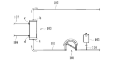
- Reference numeral 103 in the figure denotes a dialyzer as blood purification means, in which a blood channel for circulating the patient's blood and a dialysate channel for circulating dialysate are formed.
- a blood introduction port a for introducing blood by being connected to an arterial blood circuit 101 in which a blood pump 104 is disposed, and a venous blood circuit 102 are connected to lead out blood.
- a blood outlet b is formed, and at both ends of the dialysate flow path, a dialysate inlet c connected to the dialysate inlet line 107 for introducing the dialysate and a dialysate outlet line 108 are connected.
- a dialysate outlet d for leading dialysate is formed.
- the physiological pump (priming solution) in the physiological saline bag 105 is supplied to the arterial blood circuit 101 via the priming solution supply line 106 by driving the blood pump.
- the dialyzer 103 is installed so that the blood outlet port b faces upward and the physiological saline introduced from the blood inlet port a is led out from the blood outlet port b.
- the physiological circuit is filled with circulating physiological saline (see FIG. 14).
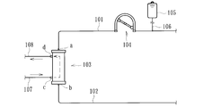
- the dialyzer 103 is turned upside down while clamping the priming solution supply line 106, and the dialyzer 103 is installed so that the blood introduction port a faces upward (see FIG. 15). Thereafter, the dialysate is introduced from the dialysate introduction line 107 and circulated through the dialysate flow path, and then the dialysate flow path is filled while being discharged from the dialysate discharge line 108. Thereby, the priming on the dialysate flow path side is performed after the blood flow path.
- the arterial blood circuit tip and the venous blood circuit tip are connected to each other, and the priming solution (physiological saline) is venous side by its own weight.
- An initial injection process for filling the blood circuit an overflow process in which the blood pump is rotated forward to allow the priming liquid to flow in the forward direction and discharged from the overflow line extending from the drip chamber of the venous blood circuit, and the blood pump is reversed.
- a technique for sequentially performing a reverse recirculation treatment process in which a priming solution is flowed in a direction opposite to the overflow process. According to such a conventional technique, it is possible to perform the priming process while maintaining the state where the blood inlet of the dialyzer is directed upward, and it is possible to simplify and automate the priming operation.
- the priming treatment can be performed while maintaining the state where the blood inlet of the dialyzer is facing upward, the priming liquid is transferred from the blood inlet to the blood outlet in the overflow process. Since it flows (priming liquid flows from the top to the bottom of the blood flow path), there is a possibility that bubbles may accumulate in the blood flow path.
- the priming liquid is then flowed from the blood outlet to the blood inlet in the reverse recirculation treatment process, so it seems that most of the bubbles escape upward, but the bubbles are not sufficiently removed.
- priming is required for a long time because a large amount of priming liquid having a high flow rate is required to remove the accumulated air bubbles.
- the present invention has been made in view of such circumstances, and can provide a blood purification device capable of easily and easily automating the priming operation and allowing the blood purification means to remove air bubbles reliably and smoothly. It is to provide the priming method.
- the invention according to claim 1 is composed of an arterial blood circuit and a venous blood circuit, a blood circuit capable of extracorporeally circulating a patient's blood from the tip of the arterial blood circuit to the tip of the venous blood circuit, and the blood
- a blood flow path that is interposed between the arterial blood circuit and the venous blood circuit of the circuit to purify blood flowing through the blood circuit, and through which a patient's blood flows through a blood purification film for purifying the blood;
- Blood purification means having a dialysate flow path through which the dialysate flows, a blood pump disposed in the arterial blood circuit, and dialysate introduction connected to the dialysate flow path inlet and outlet of the blood purification means
- a priming fluid supply line connected to the arterial blood circuit, and a priming fluid supply line capable of supplying a priming fluid into the blood circuit, and both ends of the blood purification means,
- a blood introduction port connected to the pulmonary blood circuit to introduce blood into the blood flow path, a blood outlet
- An outlet a drip chamber connected to the venous blood circuit, an overflow line extending from the air layer side of the drip chamber and capable of discharging the liquid overflowing the drip chamber to the outside, and the overflow line arbitrarily
- a valve means which can be closed or opened at the same time, and a vein side which is disposed in a predetermined part on the distal end side of the venous blood circuit and can detect bubbles in the liquid flowing through the part
- a detection signal from the venous-side bubble detection means in the blood purification apparatus comprising the bubble-detecting means, wherein the arterial blood circuit tip and the venous blood circuit tip are connected at the time of priming before treatment.
- a control means capable of controlling the blood pump and the valve means, and at the time of priming, the control means stops the blood pump and opens the valve means to thereby provide the priming liquid supply line.
- control means causes the overflow process and the circulation process to be repeatedly performed until the air bubble detection by the venous-side air bubble detection means is eliminated. To do.
- a priming liquid drip chamber is connected in the middle of the priming liquid supply line, and the control means includes the first overflow.
- a liquid pool generating step for generating a liquid pool by the priming liquid is performed in the priming liquid drip chamber.
- the control means includes the dialysate introduction line and the dialysate before the first overflow step.
- a discharge line is connected to the inlet and outlet of the dialysate flow path of the blood purification means, and a dialysate filling step is performed to fill the dialysate flow path in the blood purification means by flowing the dialysate.
- the control means depressurizes the dialysate flow path of the blood purification means during the circulation step. It is characterized by.
- the invention according to claim 6 is the blood purification apparatus according to claim 5, further comprising a water removal pump for removing water from the blood of the patient flowing in the blood purification means, and driving the water removal pump.
- a water removal pump for removing water from the blood of the patient flowing in the blood purification means, and driving the water removal pump.
- the invention according to claim 7 is the blood purification apparatus according to any one of claims 1 to 6, wherein the control means drives the blood pump forward after the overflow process and before the circulation process. It is characterized by making it.
- control means supplies a priming solution to a blood flow path of the blood purification means during the circulation step.
- the dialysis fluid is supplied to the dialysis fluid flow path.
- the invention described in claim 9 comprises an arterial blood circuit and a venous blood circuit, a blood circuit capable of extracorporeally circulating patient blood from the tip of the arterial blood circuit to the tip of the venous blood circuit, and the blood
- a blood flow path that is interposed between the arterial blood circuit and the venous blood circuit of the circuit to purify blood flowing through the blood circuit, and through which a patient's blood flows through a blood purification film for purifying the blood;
- Blood purification means having a dialysate flow path through which the dialysate flows, a blood pump disposed in the arterial blood circuit, and dialysate introduction connected to the dialysate flow path inlet and outlet of the blood purification means
- a priming fluid supply line connected to the arterial blood circuit, and a priming fluid supply line capable of supplying a priming fluid into the blood circuit, and both ends of the blood purification means,
- a blood introduction port connected to the pulmonary blood circuit to introduce blood into the blood flow path, a blood outlet port connected to the ve
- An outlet a drip chamber connected to the venous blood circuit, an overflow line extending from the air layer side of the drip chamber and capable of discharging the liquid overflowing the drip chamber to the outside, and the overflow line arbitrarily
- a valve means which can be closed or opened at the same time, and a vein side which is disposed in a predetermined part on the distal end side of the venous blood circuit and can detect bubbles in the liquid flowing through the part
- the priming method of the blood purification apparatus comprising the bubble detection means, wherein the arterial blood circuit tip and the venous blood circuit tip are connected to communicate with each other at the time of priming before treatment.
- valve means is opened to reversely supply the priming fluid from the priming fluid supply line to the drip chamber via the venous blood circuit and discharge it from the overflow line, and reverse the blood pump.
- the invention according to claim 10 is characterized in that, in the priming method of the blood purification apparatus according to claim 9, the overflow step and the circulation step are repeatedly performed until the bubble detection by the vein-side bubble detection means is eliminated.
- the invention according to claim 11 is the priming method of the blood purification apparatus according to claim 9 or 10, wherein a priming liquid drip chamber is connected in the middle of the priming liquid supply line, and before the first overflow step.
- a liquid pool generating step for generating a liquid pool by the priming liquid is performed.
- the invention described in claim 12 is the priming method of the blood purification apparatus according to any one of claims 9 to 11, wherein the dialysate introduction line and the dialysate discharge line are provided before the first overflow step at the time of priming. Is connected to the inlet and outlet of the dialysate flow path of the blood purification means, and a dialysate filling step is performed to fill the dialysate flow path in the blood purification means by flowing the dialysate.
- a thirteenth aspect of the present invention is the blood purification apparatus priming method according to any one of the ninth to twelfth aspects, wherein the inside of the dialysate flow path of the blood purification means is depressurized during the circulation step.
- the invention according to claim 14 is the priming method of the blood purification apparatus according to claim 13, further comprising a water removal pump for removing water from the blood of the patient flowing in the blood purification means, and the water removal pump.
- the inside of the dialysate flow path of the blood purification means is depressurized by driving.
- the invention according to claim 15 is the priming method for a blood purification apparatus according to any one of claims 9 to 14, wherein the blood pump is driven to rotate forward after the overflow step and before the circulation step. It is characterized by.
- the invention according to claim 16 is the priming method of the blood purification device according to any one of claims 9 to 15, wherein the priming liquid is supplied to the blood flow path of the blood purification means during the circulation step.
- a dialysate is supplied to the dialysate flow path.
- the overflow process and the circulation process are sequentially performed with the blood inlet of the blood purification means facing upward, and the venous-side bubble detection means detects the bubbles in the circulation process. Therefore, the priming operation can be easily automated with ease, and the air purifier can be surely and smoothly vented.
- the bubbles in the blood circuit are more reliably discharged outside during priming. be able to.
- the priming liquid drip chamber is provided at the time of priming. A liquid pool can be generated.
- the dialysis fluid introduction line and the dialysis fluid discharge line are connected to the dialysis fluid flow path inlet and outlet of the blood purification means before priming and before the first overflow step. Since the dialysate filling process for flowing and filling the dialysate in the dialysate flow path is performed, the air in the dialysate flow path passes through the blood purification membrane during the overflow process or the circulation process. It is possible to avoid generating bubbles in the priming liquid by reaching the flow path side.
- so-called laminated blood purification means comprising a plurality of sheet-like filtration membranes in which blood purification membranes are laminated, and so-called wet blood in which a filling liquid is preliminarily filled in the blood purification means.
- the filling liquid in the dialysate flow path is prevented from being mixed into the priming liquid by reaching the blood flow path side through the blood purification film. Can do.
- the pressure in the dialysate flow path of the blood purification means is reduced during the circulation step, the flow volume of the blood flow path can be reliably ensured, The priming solution can be distributed more smoothly.
- the blood flow channel between the sheet-like filtration membranes can be expanded to ensure the flow channel volume.
- the inside of the dialysate flow path of the blood purification means is depressurized by driving the water removal pump, so that a separate means for depressurization in the dialysate flow path is unnecessary. can do.
- the dialysis solution is supplied to the dialysate flow channel while supplying the priming solution to the blood flow channel of the blood purification means during the circulation step, so that the solute removal performance and water permeability are excellent. Even when a dialyzer is used, air can be more reliably avoided from entering the blood flow path from the dialysate flow path, and priming can be performed with the same amount of priming liquid used as a normal dialyzer. Can be made.
- the schematic diagram which shows the dialysis apparatus (blood purification apparatus) which concerns on embodiment of this invention Schematic diagram showing a state in which a liquid pool generation process (blood pump forward rotation drive) is performed by the dialyzer Schematic diagram showing a state in which a liquid pool generating step (blood pump reverse drive) is performed by the dialyzer Schematic diagram showing the state where the first overflow process by the dialysis machine is being performed Schematic diagram showing the state where the circulation process by the dialysis machine is performed Schematic diagram showing a state where an overflow process is performed by the dialysis machine Schematic diagram showing a state in which the dialysate filling process by the dialyzer is performed.
- the flowchart which shows the control content by the control means in the dialysis machine The schematic diagram which shows the state in which the overflow process by the dialysis apparatus (blood purification apparatus) which concerns on other embodiment of this invention is performed.
- the schematic diagram which shows the state in which the overflow process by the dialysis apparatus (blood purification apparatus) which concerns on other embodiment of this invention is performed.
- Overall schematic diagram showing so-called laminated blood purification means (dialyzer) applied to the dialysis apparatus (blood purification apparatus) of the present invention
- the schematic diagram which shows the inside (blood flow path and dialysate flow path) state of the blood purification means (dialyzer) at the time of the circulation process in other embodiment of this invention. Schematic showing the state where the priming process (blood flow path side) is performed by a conventional dialysis machine Schematic diagram showing a state in which the priming process (dialysate flow path side) is
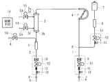
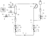
- the blood purification apparatus includes a dialysis apparatus for performing dialysis treatment. As shown in FIG. 1, a blood circuit including an arterial blood circuit 1 and a venous blood circuit 2, and an arterial blood circuit 1.
- a dialyzer 3 blood purifying means interposed between the venous blood circuit 2 and purifying blood flowing in the blood circuit, a squeezed blood pump 4 disposed in the arterial blood circuit 1, and a venous side A drip chamber 5 connected to the blood circuit 2, a storage means 7 storing physiological saline as a priming liquid, a priming fluid supply line Lc connecting the storage means 7 and the arterial blood circuit 1, and the priming
- the priming liquid drip chamber 8 is connected mainly in the middle of the liquid supply line Lc.
- An arterial puncture needle a is connected to the distal end of the arterial blood circuit 1 via a connector c, and an iron blood pump 4 is disposed in the middle, while the venous blood circuit 2 includes The vein side puncture needle b is connected to the tip thereof via a connector d, and the drip chamber 5 is connected midway. Then, when the blood pump 4 is driven with the patient punctured with the arterial puncture needle a and the venous puncture needle b, the patient's blood passes through the arterial blood circuit 1 and reaches the dialyzer 3, Blood purification is performed by the dialyzer 3, and bubbles are removed in the drip chamber 5, and then returned to the patient's body through the venous blood circuit 2. That is, the blood of the patient is purified by the dialyzer 3 while circulating externally from the tip of the arterial blood circuit 1 to the tip of the venous blood circuit 2 of the blood circuit.
- the drip chamber 5 is provided with an overflow line 6 extending from the upper part (air layer side) and having the tip opened to the atmosphere, and a liquid overflowing the drip chamber 5 (priming liquid such as physiological saline) is supplied. It is configured to be discharged to the outside.
- the overflow line 6 is provided with a solenoid valve V6 as valve means, and the overflow line 6 can be arbitrarily closed or opened.
- the dialyzer 3 includes a blood inlet 3a (blood inlet port), a blood outlet 3b (blood outlet port), a dialysate inlet 3c (dialysate channel inlet: dialysate inlet port) and a dialysate in its casing.
- a lead-out port 3d dialysate flow path outlet: dialysate lead-out port
- the dialysate inlet 3c and dialysate outlet 3d are respectively connected to a dialysate inlet line La and a dialysate outlet line Lb extending from the dialyzer body.
- a plurality of hollow fibers are accommodated in the dialyzer 3, and the hollow fibers constitute a blood purification membrane for purifying blood.
- a blood flow path (flow path between the blood inlet 3a and the blood outlet 3b) through which the patient's blood flows through the blood purification membrane and a dialysate flow path through which the dialysate flows.
- a flow path between the dialysate inlet 3c and the dialysate outlet 3d) is formed.
- the hollow fiber constituting the blood purification membrane is formed with a large number of minute holes (pores) penetrating the outer peripheral surface and the inner peripheral surface to form a hollow fiber membrane, and blood is passed through the membrane. It is configured so that impurities therein can permeate into the dialysate.
- the dual pump (not shown) is disposed across the dialysate introduction line La and the dialysate discharge line Lb in the dialyzer body, and from the patient's blood flowing in the dialyzer 3 to the dialyzer body.
- a water removal pump (not shown) for removing water is provided.
- one end of the dialysate introduction line La is connected to the dialyzer 3 (dialyte introduction port 3c), and the other end is connected to a dialysate supply device (not shown) for preparing a predetermined concentration of dialysate.
- dialysate discharge line Lb is connected to the dialyzer 3 (dialysate outlet 3d), and the other end is connected to a drain means (not shown), and the dialysate supplied from the dialysate supply device After passing through the dialysate introduction line La to the dialyzer 3, it is sent to the drainage means through the dialysate discharge line Lb.
- an electromagnetic valve V4 capable of closing and opening the flow path is connected, and in the middle of the dialysate discharge line Lb (with the duplex pump and An electromagnetic valve V5 capable of closing and opening the flow path is connected to the dialyzer 3).
- Electromagnetic valves V1 and V2 that can close and open the flow path are connected to the distal end side (near the connector c) of the arterial blood circuit 1 and the distal end side (near the connector d) of the venous blood circuit 2.
- an electromagnetic valve V3 capable of closing and opening the flow path is connected in the middle of the priming liquid supply line Lc.
- an arterial-side bubble detecting means 9 capable of detecting bubbles in the liquid flowing through the site is disposed on the distal end side of the arterial blood circuit 1, and on the distal end side of the venous blood circuit 2,
- a venous-side bubble detection means 10 that can detect bubbles in the liquid flowing through the region is provided.
- reference numerals 11 and 12 denote blood discriminators disposed on the distal end side of the arterial blood circuit 1 and the distal end side of the venous blood circuit 2
- reference numerals 13, 14, and 15 denote arterial blood circuits.
- 1 shows tube detectors respectively disposed on the distal end side of 1, the distal end side of the venous blood circuit 2, and in the middle of the priming fluid supply line Lc.
- solenoid valves V1 to V6 are capable of closing and opening the flow paths in the respective locations by the opening / closing operation as described above, and the opening / closing operation is controlled by the control means 16 such as a microcomputer. It is comprised so that.
- the control means 16 in this embodiment can receive a detection signal from the venous-side bubble detection means 10 and can control each of the electromagnetic valves V1 to V5 including the blood pump 4 and the electromagnetic valve V6 as the valve means. Are electrically connected to these components.
- the storage means 7 (so-called “physiological saline bag”) is made of a flexible transparent container and can store a predetermined volume of physiological saline (priming liquid). It is attached to the tip of a protruding pole (not shown).
- the priming liquid supply line Lc is connected to a site (connecting portion P) between the arterial puncture needle a and the arterial drip chamber 5 in the arterial blood circuit 1 and supplies physiological saline (priming liquid) in the storage means 7. It can be supplied into the blood circuit.
- a priming liquid drip chamber 8 is connected in the middle of the priming liquid supply line Lc so that the supply (dropping) of physiological saline (priming liquid) can be visually observed.
- priming before treatment (priming solution such as physiological saline is washed by flowing in the blood channel or dialysate channel, and the blood channel or dialysate channel is filled with the priming solution in advance.
- the tip of the arterial blood circuit 1 and the tip of the venous blood circuit 2 are connected to communicate with each other (specifically, the connectors c and d are connected to communicate with each other in the flow path).
- the control unit 16 outputs the detection signal (bubble detection signal) from the vein-side bubble detection unit 10 as described above during priming before treatment.
- the electromagnetic valves V1 to V5, which receive the blood pump 4 and the electromagnetic valve V6 as the valve means, can be controlled, and a reservoir of physiological saline (priming liquid) is generated in the priming liquid drip chamber 8.
- the blood pump 4 is driven in reverse.
- the electromagnetic valve V6 (valve means) is closed, and physiological saline (priming liquid) is supplied from the priming liquid supply line Lc to the arterial blood circuit 1 via the venous blood circuit 2 and dialyzer 3 (blood purification means).
- the circulation step is sequentially performed with the blood introduction port 3a of the dialyzer 3 (blood purification means) facing upward, and the venous-side bubble detection means 10 detects bubbles in the circulation step and shifts to the overflow step. It is.
- the control unit 16 according to the present embodiment repeatedly performs the overflow process and the circulation process until the bubble detection by the vein-side bubble detection unit 10 is eliminated.
- the priming process performed by the dialysis apparatus will be described based on the flowchart of FIG.
- the blood introduction port 3a of the dialyzer 3 is in a state facing upward (fixed by a fixing means (not shown)), and the connector c and the connector d are connected to each other.
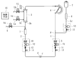
- the liquid pool generation step (S1 to S4) is performed.
- S1 drives the blood pump 4 to rotate forward so that the physiological saline solution (priming solution) in the housing means 7 is connected to the arterial blood circuit 1 via the priming solution supply line Lc. It is a process for leading to.
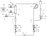
- the blood pump 4 it is determined whether or not the blood pump 4 has been normally rotated by a predetermined number (for example, 5 rotations) (S2), and when the predetermined number of rotations is reached, the blood pump 4 is reversely driven (see FIG. 3). After the blood pump 4 is driven in reverse, it is determined whether or not the blood pump 4 is driven in reverse for a predetermined number (for example, two rotations) (S4). When the predetermined number of rotations is reached, the blood pump 4 is stopped and a series of liquid pool generating steps is performed. Ends. As a result, a pool of physiological saline is generated in the drip chamber 8 for the priming solution.
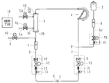
- the solenoid valves V2 and V3 are opened as shown in FIG. V1, V4 to V6 are closed.
- the solenoid valve V6 and the solenoid valve V1 as valve means are opened while maintaining the stop state of the blood pump 4, so that the priming fluid supply line Lc is passed through the venous blood circuit 2.
- a physiological saline solution (priming solution) is supplied to the drip chamber 5 by its own weight and discharged from the overflow line 6 (overflow step S5). That is, the physiological saline solution (priming solution) in the storage means 7 is caused by its own weight (drop pressure) due to the drop, between the priming solution supply line Lc, the connection part P to the tip of the arterial blood circuit 1, and veins. From the tip of the side blood circuit 2 to the drip chamber 5, it is discharged from the overflow line 6 extending from the top.
- the circulation step drives the blood pump 4 in the reverse direction (for example, a driving speed of about 100 (mL / min) is preferable) and closes the solenoid valve V6 and the solenoid valve V3 as valve means.
- physiological saline primary solution
- the priming solution supply line Lc is supplied from the priming solution supply line Lc to the artery side blood circuit 1 via the venous blood circuit 2 and the dialyzer 3.
- the physiological saline solution flows from the lower side to the upper side of the blood flow path in the dialyzer 3, and the bubbles are smoothly moved upward and removed.
- the process returns to S5 and again proceeds to the overflow step S5.
- the overflow step S5 has physiological saline contained in the drip chamber 5, but the other operations are the same as those shown in FIG.
- the solenoid valves V3 and V6 are opened.
- the dual pump (not shown) disposed across the dialysate introduction line La and the dialysate discharge line Lb is in operation, but is bypassed by a bypass line (not shown), so that the dialyzer 3 The dialysate is not supplied inside.
- the overflow process S5 and the circulation process S7 are performed again, it is determined again in S8 whether or not there is a bubble detection.
- the overflow process S5 and the circulation process S7 are repeatedly performed until the bubble detection by the vein-side bubble detection means 10 is eliminated.
- the process proceeds to S9 and a dialysate filling step (a step called so-called gas purge) is performed.
- the dialysate filling step S ⁇ b> 9 is a step in which the double pump is driven while the electromagnetic valves V ⁇ b> 4 and V ⁇ b> 5 are opened, and the dialysate flow is filled in the dialysate flow path in the dialyzer 3.
- the electromagnetic valves V3, V6 are closed, and the electromagnetic valves V1, V2, V4, V5 are open.
- the blood pump 4 Before proceeding to the dialysate filling process (gas purge) (possible during or after gas purge), the blood pump 4 is driven forward with the solenoid valves V3 and V6 opened, and the priming solution overflows. It is preferable that the gas is discharged while it is discharged. In that case, further cleaning in the dialyzer 3 can be performed.
- the blood pump 4 In the dialysate filling process (gas purge), the blood pump 4 may be driven. Further, during the dialysate filling process, the solenoid valve V3 is opened, the blood pump 4 is driven, and the water removal pump of the dialysate pipe is further driven, so that the priming solution is supplied to the blood flow path (hollow fiber) in the dialyzer 3. ) From the blood side to the dialysate side, the hollow fiber membrane can be washed (the hollow fiber pores are washed).
- the dialysate filling step by passing through the liquid pool generation step, the overflow step and the circulation step, and the dialysate filling step, it is possible to perform washing and priming of the site where blood, dialysate, etc. circulate during treatment, Air bubbles can be reliably discharged outside. Further, in the present embodiment, since the blood introduction port 3a of the dialyzer 3 is directed upward throughout all the priming steps, the upside down operation of the dialyzer 3 is not required, and the priming step is facilitated. In addition to being able to automate, the dialyzer 3 can be quickly and surely vented.
- the venous-side bubble detection means 10 detects bubbles in the circulation step and shifts to the overflow step, the priming operation can be easily automated and the dialyzer 3 (blood The air purifying means) can be surely and smoothly performed.
- the physiological saline solution (priming solution) is not supplied from the upper side to the lower side with respect to the blood flow path of the dialyzer 3, so that a subsequent air lock or the like can be reliably avoided.
- the overflow process and the circulation process are repeatedly performed until the bubble detection by the venous-side bubble detection means 10 is eliminated, so that the bubbles in the blood circuit can be more reliably discharged to the outside during priming. Can do. Further, before the first overflow process, a liquid pool generating process for generating a pool of physiological saline (priming liquid) is performed in the priming liquid drip chamber 8, so that the liquid pool in the priming liquid drip chamber 8 at the time of priming is used. Can be generated.
- priming work can be performed by a series of controls by the control means 16
- priming can be easily automated and work by workers can be significantly reduced.
- the operation as in the present embodiment is possible, so that the blood purification apparatus (dialysis apparatus) according to the present invention can be used by diverting the existing blood circuit almost as it is. it can.
- the control means 16 connects the dialysate introduction line La and the dialysate discharge line Lb to the dialysate introduction port 3c and the dialysate outlet 3b of the dialyzer 3 (blood purification means).
- a dialysate filling step of connecting and filling the dialysate flow path in the dialyzer 3 with a dialysate may be performed.
- the air in the dialysate flow path reaches the blood flow path side through the blood purification membrane, thereby generating bubbles in the priming liquid. It can be avoided.
- dialysate introduction line La and the dialysate discharge line Lb are connected to the dialyzer 3 via a coupler or the like at the start of priming, foreign substances such as dust enter the dialyzer 3 at the time of priming. Can be prevented, and safety can be further improved.
- the dialysate introduction line La and the dialysate discharge line Lb are connected to the dialysate inlet 3c and the dialysate outlet 3b of the dialyzer 3 (blood purification means).
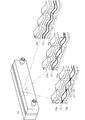
- the dialysate filling process is performed in which the dialysate flow is filled in the dialysate flow path in the dialyzer 3, it can also be suitable for a so-called laminated blood purification means.
- the laminated blood purification means is formed by forming a plurality of layers of fixing plates 20a in a housing 20, and sandwiching a sheet-like filtration membrane 21 between the fixing plates 20a. At the same time, a blood flow path through which blood flows is formed between the filtration membranes 21, and a dialysate flow path through which dialysate flows is provided between the filtration membrane 21 and the fixing plate 20a.
- the laminated blood purification means dialyzer
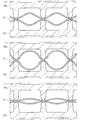
- the liquid (priming solution) is at a normal fluid pressure in the blood channel. Or blood) (see FIG. 12A), when liquid flows at a high hydraulic pressure (see FIG.
- the dialysate introduction line La and the dialysate discharge line Lb are connected to the dialysate introduction port 3c and the dialysate outlet 3b of the dialyzer 3 (blood purification means). Then, if a dialysate filling process is performed in which the dialysate is flowed and filled in the dialysate flow path in the dialyzer 3, a so-called wet type in which the dialysate 3 (blood purification means) is filled with a filling solution in advance.
- the filling liquid in the dialysate flow path reaches the blood flow path side through the blood purification film and is mixed into the priming liquid. Can be avoided.
- the control means 16 depressurizes the inside of the dialysate flow path of the dialyzer 3 (blood purification means) during the circulation step S7 to make negative pressure (negative pressure).
- the blood purification apparatus includes the water removal pump for removing water from the blood of the patient flowing in the dialyzer 3 (blood purification means). By driving the pump, the dialysate flow path of the dialyzer 3 (blood purification means) can be depressurized to a negative pressure.
- the dewatering pump is usually composed of a pump formed in a line that bypasses the double pump (driving means for supplying dialysate) in the dialysate discharge line Lb.
- the inside of the dialysate flow path of the dialyzer 3 (blood purification means) is depressurized to be a negative pressure, the flow volume of the blood flow path can be reliably ensured, and the blood The distribution of the priming liquid in the flow path can be performed more smoothly.
- the blood flow path between the sheet-like filtration membranes 21 is expanded to ensure the flow path volume. be able to.
- the blood pump 4 is normally driven for a predetermined time or a predetermined number of rotations. Also good. Specifically, when the overflow step S5 is completed, the blood pump 4 is driven to rotate forward relatively slowly, so that, for example, a filling liquid (distilled water) preliminarily filled in the blood flow path of the dialyzer 3 and the storage are stored. The priming liquid supplied from the means 7 flows to the chamber 5 side and fills this line (the flow path from the blood outlet 3b of the dialyzer 3 to the drip chamber 5 in the venous blood circuit 2). During the forward rotation, it is preferable to close the electromagnetic valve V6 (valve means) while keeping the electromagnetic valve V3 open.
- V6 valve means
- the air in the flow path from the blood outlet 3b of the dialyzer 3 to the drip chamber 5 in the venous blood circuit 2 can be removed before the circulation step S7, and the priming operation Can be performed more smoothly and in a short time.
- a so-called dry type (which is not filled with a filling liquid) dialyzer blood purification means
- a large amount of priming liquid is required to remove it.
- the priming is wasted and the priming time is increased.
- the problem can be solved and the priming operation can be performed efficiently. it can.
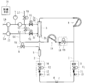
- this invention is not limited to this, It is good also as what supplies a priming liquid irrespective of its own weight in an overflow process.
- the priming fluid supply line Ld is connected between the downstream portion of the dialysate introduction line La from the duplex pump 17 and the upstream side of the blood pump 4 of the arterial blood circuit 1.
- reference numerals 18 and V9 denote a tube detector and a solenoid valve disposed in the middle of the priming liquid supply line Ld
- reference numerals Le and V7 denote a dialysate introduction line La and a dialysate.
- the bypass line communicating with the discharge line Lb and the solenoid valves disposed in the middle thereof, the symbols Lf and V8, are disposed in the middle of the supply line that can supply the dialysate to the dialysate discharge line Lb.
- a solenoid valve is shown.
- the dialysis fluid (from the priming fluid supply line Ld to the drip chamber 5 via the venous blood circuit 2 is driven by opening the solenoid valve V8 and driving the dual pump 17. Priming liquid) can be supplied and discharged from the overflow line 6.
- the solenoid valves V4, V5, V7 are closed and the solenoid valves V6, V8 are opened, and the dialysis of the duplex pump 17 is performed via the supply line Lf.
- the dialysate is introduced into the liquid discharge line Lb.
- the other embodiment compared to the case of supplying the priming liquid using its own weight as in the previous embodiment, there is not much restriction on the handling of the priming liquid supply line Ld because no drop is required. . Moreover, since the supply amount of the dialysis fluid as the priming fluid can be controlled by the flow rate of the duplex pump 17, the overflow process can be performed more accurately and reliably. Furthermore, since the dialysate is generally cheaper than the physiological saline, the cost can be suppressed.
- a dialysate pump 19 (an iron-type pump similar to the blood pump 4) is disposed in the middle of the priming solution supply line Ld.
- the dialysate pump 19 may be driven to supply dialysate.
- the supply amount of the dialysate as the priming solution can be controlled by the flow rate of the dialysate pump 19, the overflow process can be performed more accurately and reliably.
- the dialysate is generally cheaper than the physiological saline, the cost can be suppressed.
- a predetermined amount of physiological saline (priming solution) is sent to the blood channel ⁇ by the blood pump 4 (for example, the blood flow).
- the blood pump 4 for example, the blood flow
- the solenoid valves V4 and V5 are open at the time when the fluid is fed to about half of the path ⁇ .
- the fluid level of the blood channel ⁇ should not be exceeded (always, the fluid level on the dialysate channel ⁇ side is lower than the fluid level on the blood channel ⁇ side).
- the dual pump is operated at a lower speed than the blood pump 4 or the single pump is used for one shot (16.7 (mL)) with respect to the amount of liquid delivered (about 20 (mL))
- Operate etc. Operate etc.
- the blood flow path ⁇ is slightly negative pressure, so that the blood flow path ⁇ (hollow fiber) from the dialysate flow path ⁇ (outside the hollow fiber membrane). Air may enter the inside.
- the physiological saline solution (priming solution) that should originally be sent in the circulation step (S7) is not sent, and the air in the dialysate flow path ⁇ is sent, so the number of overflow steps (S5) increases.
- a larger amount of physiological saline (priming solution) than the actual filling amount may be required.
- the liquid pool generation steps (S1 to S4) are automatically performed.
- the liquid pool generation steps (S1 to S4) may not be performed or may be performed manually.
- the physiological saline solution as the priming solution is supplied from the storage means 7, but another priming solution different from the physiological saline solution may be supplied.
- the present invention is applied to a dialysis apparatus used at the time of dialysis treatment, but is used in other apparatuses that can purify the patient's blood while circulating it outside the body (for example, blood filtration dialysis, blood filtration, AFBF).
- the present invention may be applied to blood purification devices, plasma adsorption devices, and the like.
- the blood pump is stopped and the valve means is opened to supply the priming liquid from the priming liquid supply line to the drip chamber through the venous blood circuit and discharge it from the overflow line, and the blood pump
- the blood introduction port of the blood purification means moves upward in the circulation process in which the valve means is closed while the valve means is closed and the priming liquid is supplied from the priming liquid supply line to the arterial blood circuit via the venous blood circuit and the blood purification means. If it is a blood purification device and its priming method that are sequentially performed in a facing state and moved to the overflow step by detecting bubbles in the venous-side bubble detection means in the circulation step, it is also applicable to other forms and uses be able to.
Landscapes
- Health & Medical Sciences (AREA)
- Heart & Thoracic Surgery (AREA)
- Vascular Medicine (AREA)
- Biomedical Technology (AREA)
- Engineering & Computer Science (AREA)
- Anesthesiology (AREA)
- Cardiology (AREA)
- Hematology (AREA)
- Life Sciences & Earth Sciences (AREA)
- Animal Behavior & Ethology (AREA)
- General Health & Medical Sciences (AREA)
- Public Health (AREA)
- Veterinary Medicine (AREA)
- External Artificial Organs (AREA)
Priority Applications (3)
| Application Number | Priority Date | Filing Date | Title |
|---|---|---|---|
| US12/680,298 US8343085B2 (en) | 2008-12-16 | 2009-12-15 | Blood purification apparatus and priming method thereof |
| CN200980150387.6A CN102245226B (zh) | 2008-12-16 | 2009-12-15 | 血液净化装置及其预充方法 |
| EP09833194.5A EP2361643B1 (en) | 2008-12-16 | 2009-12-15 | Blood purifier and method of priming same |
Applications Claiming Priority (6)
| Application Number | Priority Date | Filing Date | Title |
|---|---|---|---|
| JP2008319196 | 2008-12-16 | ||
| JP2008-319196 | 2008-12-16 | ||
| JP2009108582 | 2009-04-28 | ||
| JP2009-108582 | 2009-04-28 | ||
| JP2009124931A JP5294985B2 (ja) | 2008-12-16 | 2009-05-25 | 血液浄化装置及びそのプライミング方法 |
| JP2009-124931 | 2009-05-25 |
Publications (1)
| Publication Number | Publication Date |
|---|---|
| WO2010070886A1 true WO2010070886A1 (ja) | 2010-06-24 |
Family
ID=42268566
Family Applications (1)
| Application Number | Title | Priority Date | Filing Date |
|---|---|---|---|
| PCT/JP2009/006897 Ceased WO2010070886A1 (ja) | 2008-12-16 | 2009-12-15 | 血液浄化装置及びそのプライミング方法 |
Country Status (5)
| Country | Link |
|---|---|
| US (1) | US8343085B2 (enExample) |
| EP (1) | EP2361643B1 (enExample) |
| JP (1) | JP5294985B2 (enExample) |
| CN (1) | CN102245226B (enExample) |
| WO (1) | WO2010070886A1 (enExample) |
Cited By (3)
| Publication number | Priority date | Publication date | Assignee | Title |
|---|---|---|---|---|
| JP2012192102A (ja) * | 2011-03-17 | 2012-10-11 | Nikkiso Co Ltd | 血液浄化装置 |
| CN105705175A (zh) * | 2013-11-11 | 2016-06-22 | 日机装株式会社 | 血液净化装置及其预充方法 |
| JP2020096876A (ja) * | 2014-04-29 | 2020-06-25 | アウトセット・メディカル・インコーポレイテッドOutset Medical, Inc. | 透析システムおよび方法 |
Families Citing this family (63)
| Publication number | Priority date | Publication date | Assignee | Title |
|---|---|---|---|---|
| US8834399B2 (en) * | 2010-12-07 | 2014-09-16 | Zoll Lifebridge Gmbh | Cardiopulmonary apparatus and methods for preserving organ viability |
| US8040493B2 (en) | 2007-10-11 | 2011-10-18 | Fresenius Medical Care Holdings, Inc. | Thermal flow meter |
| US9358331B2 (en) | 2007-09-13 | 2016-06-07 | Fresenius Medical Care Holdings, Inc. | Portable dialysis machine with improved reservoir heating system |
| US8105487B2 (en) | 2007-09-25 | 2012-01-31 | Fresenius Medical Care Holdings, Inc. | Manifolds for use in conducting dialysis |
| US8535522B2 (en) | 2009-02-12 | 2013-09-17 | Fresenius Medical Care Holdings, Inc. | System and method for detection of disconnection in an extracorporeal blood circuit |
| US9308307B2 (en) | 2007-09-13 | 2016-04-12 | Fresenius Medical Care Holdings, Inc. | Manifold diaphragms |
| US8240636B2 (en) | 2009-01-12 | 2012-08-14 | Fresenius Medical Care Holdings, Inc. | Valve system |
| US8597505B2 (en) | 2007-09-13 | 2013-12-03 | Fresenius Medical Care Holdings, Inc. | Portable dialysis machine |
| CA3057807C (en) | 2007-11-29 | 2021-04-20 | Thomas P. Robinson | System and method for conducting hemodialysis and hemofiltration |
| CN105148344B (zh) | 2008-10-07 | 2019-06-11 | 弗雷塞尼斯医疗保健控股公司 | 用于透析系统的充灌系统和方法 |
| AU2009320007B2 (en) | 2008-10-30 | 2014-12-04 | Fresenius Medical Care Holdings, Inc. | Modular, portable dialysis system |
| WO2010114932A1 (en) | 2009-03-31 | 2010-10-07 | Xcorporeal, Inc. | Modular reservoir assembly for a hemodialysis and hemofiltration system |
| US8753515B2 (en) | 2009-12-05 | 2014-06-17 | Home Dialysis Plus, Ltd. | Dialysis system with ultrafiltration control |
| US8501009B2 (en) | 2010-06-07 | 2013-08-06 | State Of Oregon Acting By And Through The State Board Of Higher Education On Behalf Of Oregon State University | Fluid purification system |
| CN103619374B (zh) | 2010-12-07 | 2017-07-11 | 措尔生命桥梁有限责任公司 | 使过滤器逐步注满的用于体外血液治疗的装置的填充和排气的方法及系统 |
| WO2012125470A1 (en) * | 2011-03-11 | 2012-09-20 | Fenwal, Inc. | Membrane separation devices, systems and methods employing same and data management systems and methods |
| JP5707190B2 (ja) * | 2011-03-17 | 2015-04-22 | 日機装株式会社 | 血液浄化装置 |
| WO2013052680A2 (en) | 2011-10-07 | 2013-04-11 | Home Dialysis Plus, Ltd. | Heat exchange fluid purification for dialysis system |
| JP6478393B2 (ja) | 2012-08-09 | 2019-03-06 | 日機装株式会社 | 血液浄化装置及びそのプライミング方法 |
| WO2014099779A1 (en) * | 2012-12-20 | 2014-06-26 | Gambro Renal Products, Inc. | Blood set component connection detection |
| US9201036B2 (en) | 2012-12-21 | 2015-12-01 | Fresenius Medical Care Holdings, Inc. | Method and system of monitoring electrolyte levels and composition using capacitance or induction |
| US9157786B2 (en) | 2012-12-24 | 2015-10-13 | Fresenius Medical Care Holdings, Inc. | Load suspension and weighing system for a dialysis machine reservoir |
| EP3398628B1 (en) | 2013-02-06 | 2022-04-06 | NxStage Medical Inc. | Fluid circuit priming methods, devices, and systems |
| DE102013011715A1 (de) * | 2013-07-15 | 2015-01-15 | Fresenius Medical Care Deutschland Gmbh | Verfahren zum Steuern einer Blutbehandlungsvorrichtung und Vorrichtungen |
| US9354640B2 (en) | 2013-11-11 | 2016-05-31 | Fresenius Medical Care Holdings, Inc. | Smart actuator for valve |
| DE102014011673A1 (de) | 2014-08-05 | 2016-02-11 | Fresenius Medical Care Deutschland Gmbh | Verfahren zum Auswaschen von Gasblasen in einem extrakoporalen Blutkreislauf |
| JP6424041B2 (ja) * | 2014-08-07 | 2018-11-14 | 日機装株式会社 | 血液浄化装置 |
| JP5851003B1 (ja) | 2014-09-12 | 2016-02-03 | 日機装株式会社 | 血液浄化装置 |
| US9987411B2 (en) | 2014-12-19 | 2018-06-05 | Fenwal, Inc. | Methods and systems for priming a biological fluid processing circuit |
| JP6517023B2 (ja) | 2015-01-23 | 2019-05-22 | 日機装株式会社 | 血液浄化装置 |
| US10576197B2 (en) | 2015-05-12 | 2020-03-03 | Nikkiso Co., Ltd. | Blood purification device and priming method |
| JP6516559B2 (ja) | 2015-05-21 | 2019-05-22 | 日機装株式会社 | 血液浄化装置 |
| JP6613062B2 (ja) | 2015-06-24 | 2019-11-27 | 日機装株式会社 | 血液浄化装置及び血液浄化システム |
| CN107683151B (zh) | 2015-06-24 | 2020-07-28 | 日机装株式会社 | 血液净化装置 |
| CN105477708A (zh) * | 2015-08-08 | 2016-04-13 | 常州华岳微创医疗器械有限公司 | 一种可装卸管路的血液净化装置 |
| JP6636770B2 (ja) * | 2015-10-30 | 2020-01-29 | 日機装株式会社 | 血液浄化装置 |
| JP6111351B1 (ja) | 2016-01-25 | 2017-04-05 | 日機装株式会社 | 血液浄化装置 |
| CN113304341B (zh) * | 2016-03-31 | 2024-05-14 | 旭化成医疗株式会社 | 血液净化系统和其启动加注方法 |
| JP6762772B2 (ja) * | 2016-06-08 | 2020-09-30 | 日機装株式会社 | 血液浄化装置及びその接続確認方法 |
| CN106215265B (zh) * | 2016-08-16 | 2018-09-11 | 珠海健帆生物科技股份有限公司 | 血液净化器排气方法 |
| ES3037938T3 (en) | 2016-08-19 | 2025-10-08 | Outset Medical Inc | Peritoneal dialysis system and methods |
| JP6998112B2 (ja) | 2016-09-12 | 2022-01-18 | 日機装株式会社 | 血液浄化装置 |
| JP6826852B2 (ja) | 2016-09-23 | 2021-02-10 | 日機装株式会社 | 血液浄化装置 |
| CN108114334B (zh) * | 2016-11-28 | 2024-01-12 | 健帆生物科技集团股份有限公司 | 血液净化器、血液净化系统及其预冲方法 |
| CN110461388B (zh) * | 2017-03-31 | 2022-02-25 | 旭化成医疗株式会社 | 血液净化装置及其启动加注方法 |
| WO2018186495A1 (ja) * | 2017-04-07 | 2018-10-11 | 株式会社アルチザンラボ | 注射針用キャップ及び透析回路プライミング用デバイス |
| US11420037B2 (en) * | 2017-08-04 | 2022-08-23 | Fresenius Medical Care Holdings, Inc. | Infusion methods for extracoporeal systems |
| JP6462077B1 (ja) | 2017-09-07 | 2019-01-30 | 日機装株式会社 | 血液浄化装置及びその気泡の排出方法 |
| JP6464238B1 (ja) | 2017-09-07 | 2019-02-06 | 日機装株式会社 | 血液浄化装置及びその気泡の排出方法 |
| US20210178046A1 (en) * | 2017-12-21 | 2021-06-17 | Gambro Lundia Ab | Dialysis system having carbon dioxide generation and prime |
| EP3505200B1 (en) | 2017-12-29 | 2020-09-09 | Gambro Lundia AB | Apparatus for extracorporeal blood treatment |
| JP6488048B2 (ja) * | 2018-05-24 | 2019-03-20 | 日機装株式会社 | 血液浄化装置 |
| CA3109237A1 (en) | 2018-08-23 | 2020-02-27 | Outset Medical, Inc. | Systems and methods for priming dialysis tubing sets |
| US12390565B2 (en) | 2019-04-30 | 2025-08-19 | Outset Medical, Inc. | Dialysis systems and methods |
| DE102020122937A1 (de) | 2020-09-02 | 2022-03-03 | B.Braun Avitum Ag | Automatisches Primen und Spülen einer extrakorporalen Blutbehandlungsvorrichtung |
| DE102020125291A1 (de) | 2020-09-28 | 2022-03-31 | B.Braun Avitum Ag | Automatisches Primen einer extrakorporalen Blutbehandlungsvorrichtung unter Verwendung eines Push-Pull-Verfahrens |
| ES3007240T3 (en) | 2020-10-30 | 2025-03-19 | Bellco Srl | Dialysis cassette with pump features |
| US12318528B2 (en) | 2020-10-30 | 2025-06-03 | Mozarc Medical Us Llc | Variable orifice fistula graft |
| US11904281B2 (en) | 2021-02-11 | 2024-02-20 | Fenwal, Inc. | Spinning membrane separator priming systems and methods |
| CN114344596B (zh) * | 2021-12-27 | 2023-07-25 | 健帆生物科技集团股份有限公司 | 血液灌流器的排气控制系统 |
| CN114209906A (zh) * | 2022-01-04 | 2022-03-22 | 山东威高血液净化制品股份有限公司 | 一种测试血室压力降的自动化装置和方法 |
| CN119236210B (zh) * | 2024-08-29 | 2025-09-23 | 健帆生物科技集团股份有限公司 | 血液净化设备的泵秤联合校准控制方法、血液净化设备及存储介质 |
| CN119680040B (zh) * | 2024-12-03 | 2025-11-14 | 中国人民解放军空军军医大学 | 适用于院外应急救援的ecmo快速预充系统及使用方法 |
Citations (6)
| Publication number | Priority date | Publication date | Assignee | Title |
|---|---|---|---|---|
| JPH0838597A (ja) * | 1994-07-29 | 1996-02-13 | Nikkiso Co Ltd | 血液浄化回路の自動プライミング処理方法および装置 |
| JP2000093449A (ja) | 1998-09-24 | 2000-04-04 | Nikkiso Co Ltd | 加温冷却自在型chdf装置 |
| JP2005046404A (ja) * | 2003-07-30 | 2005-02-24 | Jms Co Ltd | 気泡検出システム、該気泡検出システムを備えた血液透析回路 |
| WO2006073166A1 (ja) | 2005-01-07 | 2006-07-13 | Jms Co. | 自動プライミング方法 |
| JP2007135885A (ja) * | 2005-11-18 | 2007-06-07 | Nikkiso Co Ltd | 血液浄化装置及びその穿刺針の接続状態判別方法 |
| JP2007275213A (ja) * | 2006-04-05 | 2007-10-25 | Nikkiso Co Ltd | 血液回路のプライミング方法 |
Family Cites Families (3)
| Publication number | Priority date | Publication date | Assignee | Title |
|---|---|---|---|---|
| US5951870A (en) * | 1997-10-21 | 1999-09-14 | Dsu Medical Corporation | Automatic priming of blood sets |
| JP3937436B2 (ja) * | 2003-06-05 | 2007-06-27 | ニプロ株式会社 | 血液浄化装置および血液回路の自動プライミング方法 |
| JP4613831B2 (ja) * | 2006-01-17 | 2011-01-19 | ニプロ株式会社 | 血液浄化装置及びその血液循環路の自動プライミング方法 |
-
2009
- 2009-05-25 JP JP2009124931A patent/JP5294985B2/ja active Active
- 2009-12-15 EP EP09833194.5A patent/EP2361643B1/en active Active
- 2009-12-15 CN CN200980150387.6A patent/CN102245226B/zh active Active
- 2009-12-15 WO PCT/JP2009/006897 patent/WO2010070886A1/ja not_active Ceased
- 2009-12-15 US US12/680,298 patent/US8343085B2/en active Active
Patent Citations (6)
| Publication number | Priority date | Publication date | Assignee | Title |
|---|---|---|---|---|
| JPH0838597A (ja) * | 1994-07-29 | 1996-02-13 | Nikkiso Co Ltd | 血液浄化回路の自動プライミング処理方法および装置 |
| JP2000093449A (ja) | 1998-09-24 | 2000-04-04 | Nikkiso Co Ltd | 加温冷却自在型chdf装置 |
| JP2005046404A (ja) * | 2003-07-30 | 2005-02-24 | Jms Co Ltd | 気泡検出システム、該気泡検出システムを備えた血液透析回路 |
| WO2006073166A1 (ja) | 2005-01-07 | 2006-07-13 | Jms Co. | 自動プライミング方法 |
| JP2007135885A (ja) * | 2005-11-18 | 2007-06-07 | Nikkiso Co Ltd | 血液浄化装置及びその穿刺針の接続状態判別方法 |
| JP2007275213A (ja) * | 2006-04-05 | 2007-10-25 | Nikkiso Co Ltd | 血液回路のプライミング方法 |
Cited By (4)
| Publication number | Priority date | Publication date | Assignee | Title |
|---|---|---|---|---|
| JP2012192102A (ja) * | 2011-03-17 | 2012-10-11 | Nikkiso Co Ltd | 血液浄化装置 |
| CN105705175A (zh) * | 2013-11-11 | 2016-06-22 | 日机装株式会社 | 血液净化装置及其预充方法 |
| JP2020096876A (ja) * | 2014-04-29 | 2020-06-25 | アウトセット・メディカル・インコーポレイテッドOutset Medical, Inc. | 透析システムおよび方法 |
| JP7191880B2 (ja) | 2014-04-29 | 2022-12-19 | アウトセット・メディカル・インコーポレイテッド | 透析システムおよび方法 |
Also Published As
| Publication number | Publication date |
|---|---|
| US8343085B2 (en) | 2013-01-01 |
| JP2010273693A (ja) | 2010-12-09 |
| CN102245226B (zh) | 2014-03-05 |
| EP2361643B1 (en) | 2016-06-01 |
| CN102245226A (zh) | 2011-11-16 |
| JP5294985B2 (ja) | 2013-09-18 |
| EP2361643A4 (en) | 2015-05-20 |
| EP2361643A1 (en) | 2011-08-31 |
| US20110213289A1 (en) | 2011-09-01 |
Similar Documents
| Publication | Publication Date | Title |
|---|---|---|
| JP5294985B2 (ja) | 血液浄化装置及びそのプライミング方法 | |
| JP5205036B2 (ja) | 血液浄化装置 | |
| JP6685374B2 (ja) | 血液浄化装置及びそのプライミング方法 | |
| JP5808062B2 (ja) | 血液浄化装置及びそのプライミング方法 | |
| JP5247864B2 (ja) | 血液浄化装置 | |
| WO2009153955A1 (ja) | 血液浄化装置及びそのプライミング方法 | |
| CN103732270B (zh) | 血液净化装置 | |
| JP5699008B2 (ja) | 血液浄化装置 | |
| JP5319381B2 (ja) | 血液浄化装置及びその気泡除去方法 | |
| JP2007282737A (ja) | プライミング液用ドリップチャンバの液面調整方法 | |
| JP2013248334A (ja) | 血液浄化装置及びそのプライミング方法 | |
| WO2013031965A1 (ja) | 血液浄化装置 | |
| JP5192241B2 (ja) | 血液浄化装置及びそのプライミング方法 | |
| JP2011136003A (ja) | 血液浄化装置及びそのプライミング方法 | |
| JP6933439B2 (ja) | 血液浄化装置 | |
| JP6464238B1 (ja) | 血液浄化装置及びその気泡の排出方法 | |
| JP6462077B1 (ja) | 血液浄化装置及びその気泡の排出方法 | |
| CN108348672B (zh) | 血液净化装置 | |
| JP6266695B2 (ja) | 血液浄化装置及びそのプライミング方法 | |
| JP2009153640A (ja) | 血液浄化装置及びそのプライミング方法 | |
| JP6462076B1 (ja) | 血液浄化装置及びそのプライミング方法 | |
| JP6357496B2 (ja) | 血液浄化装置 | |
| HK1145818A (en) | Blood dialysis apparatus |
Legal Events
| Date | Code | Title | Description |
|---|---|---|---|
| WWE | Wipo information: entry into national phase |
Ref document number: 200980150387.6 Country of ref document: CN |
|
| WWE | Wipo information: entry into national phase |
Ref document number: 12680298 Country of ref document: US |
|
| 121 | Ep: the epo has been informed by wipo that ep was designated in this application |
Ref document number: 09833194 Country of ref document: EP Kind code of ref document: A1 |
|
| NENP | Non-entry into the national phase |
Ref country code: DE |
|
| WWE | Wipo information: entry into national phase |
Ref document number: 2009833194 Country of ref document: EP |