EP2361643B1 - Blood purifier and method of priming same - Google Patents
Blood purifier and method of priming same Download PDFInfo
- Publication number
- EP2361643B1 EP2361643B1 EP09833194.5A EP09833194A EP2361643B1 EP 2361643 B1 EP2361643 B1 EP 2361643B1 EP 09833194 A EP09833194 A EP 09833194A EP 2361643 B1 EP2361643 B1 EP 2361643B1
- Authority
- EP
- European Patent Office
- Prior art keywords
- blood
- dialysate
- priming
- flow route
- blood purification
- Prior art date
- Legal status (The legal status is an assumption and is not a legal conclusion. Google has not performed a legal analysis and makes no representation as to the accuracy of the status listed.)
- Active
Links
Images


Classifications
-
- A—HUMAN NECESSITIES
- A61—MEDICAL OR VETERINARY SCIENCE; HYGIENE
- A61M—DEVICES FOR INTRODUCING MEDIA INTO, OR ONTO, THE BODY; DEVICES FOR TRANSDUCING BODY MEDIA OR FOR TAKING MEDIA FROM THE BODY; DEVICES FOR PRODUCING OR ENDING SLEEP OR STUPOR
- A61M1/00—Suction or pumping devices for medical purposes; Devices for carrying-off, for treatment of, or for carrying-over, body-liquids; Drainage systems
- A61M1/36—Other treatment of blood in a by-pass of the natural circulatory system, e.g. temperature adaptation, irradiation ; Extra-corporeal blood circuits
- A61M1/3621—Extra-corporeal blood circuits
- A61M1/3643—Priming, rinsing before or after use
- A61M1/3644—Mode of operation
- A61M1/3646—Expelling the residual body fluid after use, e.g. back to the body
-
- A—HUMAN NECESSITIES
- A61—MEDICAL OR VETERINARY SCIENCE; HYGIENE
- A61M—DEVICES FOR INTRODUCING MEDIA INTO, OR ONTO, THE BODY; DEVICES FOR TRANSDUCING BODY MEDIA OR FOR TAKING MEDIA FROM THE BODY; DEVICES FOR PRODUCING OR ENDING SLEEP OR STUPOR
- A61M1/00—Suction or pumping devices for medical purposes; Devices for carrying-off, for treatment of, or for carrying-over, body-liquids; Drainage systems
- A61M1/36—Other treatment of blood in a by-pass of the natural circulatory system, e.g. temperature adaptation, irradiation ; Extra-corporeal blood circuits
- A61M1/3621—Extra-corporeal blood circuits
- A61M1/3643—Priming, rinsing before or after use
- A61M1/3644—Mode of operation
- A61M1/3649—Mode of operation using dialysate as priming or rinsing liquid
-
- A—HUMAN NECESSITIES
- A61—MEDICAL OR VETERINARY SCIENCE; HYGIENE
- A61M—DEVICES FOR INTRODUCING MEDIA INTO, OR ONTO, THE BODY; DEVICES FOR TRANSDUCING BODY MEDIA OR FOR TAKING MEDIA FROM THE BODY; DEVICES FOR PRODUCING OR ENDING SLEEP OR STUPOR
- A61M1/00—Suction or pumping devices for medical purposes; Devices for carrying-off, for treatment of, or for carrying-over, body-liquids; Drainage systems
- A61M1/36—Other treatment of blood in a by-pass of the natural circulatory system, e.g. temperature adaptation, irradiation ; Extra-corporeal blood circuits
- A61M1/3621—Extra-corporeal blood circuits
- A61M1/3626—Gas bubble detectors
Definitions
- the present invention relates to a blood purification apparatus for extracorporeally circulating blood of a patient to purify the blood used e.g. in the dialysis treatment using a dialyzer and a method for priming the blood purification apparatus.
- the blood circuits mainly comprises an arterial blood circuit and a venous blood circuit adapted to be connected to a dialyzer (blood purification means) provided e.g. with hollow fiber membranes.
- a dialyzer blood purification means
- An arterial puncture needle and a venous puncture needle can be mounted on tips respectively of the arterial blood circuit and the venous blood circuit and thus the extracorporeal circulation of the blood can be performed in the dialysis treatment with the puncture needles being punctured to a body of a patient.
- a peristaltic blood pump is arranged in the arterial blood circuit and the blood of a patient is adapted to be fed to the dialyzer by driving the blood pump.
- an arterial drip chamber and a venous drip chamber are connected to the arterial blood circuit and the venous blood circuit respectively and thus the blood is returned to a body of a patient after removal of bubbles therefrom.
- a priming solution supplying line (physiological saline solution line) is connected to the arterial blood circuit at the upstream side (i.e. arterial puncture needle side) of the blood pump via a T-joint for supplying the physiological saline solution during the priming and the autotransfusion.
- the dialyzer is structured so that the priming is performed before the dialysis treatment by supplying the physiological saline solution and charging the structural elements such as blood circuits and drip chambers connected thereto with the physiological saline solution and then the physiological saline solution is replaced with blood remained in the blood circuits after the dialysis treatment and finally the remained blood is returned to a patient for performing the autotransfusion.
- a dialysis apparatus furnished with the priming solution supplying line is disclosed e.g. in Patent Document 1 noticed below.
- a reference numeral 103 denotes a dialyzer functioning as a blood purification means in which a blood flow route for passing blood of a patient therethrough and a dialysate flow route for passing dialysate therethrough.
- the blood flow route has on its opposite ends a blood inlet port "a" for introducing the blood to be connected to a arterial blood circuit 101 on which a blood pump 104 is arranged and a blood outlet port "b" for discharging the blood to be connected to a venous blood circuit 102.
- dialysate flow route has on its opposite ends a dialysate inlet port "c" for introducing the dialysate to be connected to a dialysate introducing line 107 and a dialysate outlet port “d" for discharging the dialysate to be connected to a dialysate discharging line 108.
- physiological saline solution (priming solution) in a physiological saline solution bag 105 Prior to the dialysis treatment physiological saline solution (priming solution) in a physiological saline solution bag 105 is supplied to the arterial blood circuit 101 via a priming solution supplying line 106 by driving the blood pump 104.
- the dialyzer 103 is arranged so that the blood outlet port "b" is positioned upward and the blood flow route within the dialyzer 103 and the blood circuit are charged with the physiological saline solution by discharging the physiological saline solution introduced into the dialyzer 103 from the blood outlet port "b" through the blood flow route (see Fig. 14 ).
- the dialyzer 103 is arranged upside down with clamping the priming solution supplying line 106 so that the blood inlet port "a" is positioned upward (see Fig. 15 ). Then after having introduced the dialysate from the dialysate introducing line 107 and passed through the dialysate flow route within the dialyzer 103, the dialysate flow route is charged with the dialysate by discharging the dialysate from the dialysate discharging line 108. Thus the priming of the dialysate flow route has been completed following the priming of the blood flow route.
- a priming method has a problem of requiring a long priming duration because of increase of priming operation steps due to requirement of arranging the dialyzer 103 upside down before performing the priming of the dialysate flow route and after the priming of the blood flow route.
- extension of the priming time (duration) causes other problems of delay of commence of dialysis treatment and thus of increase of burden both for a patient and medical personnel.
- US 5 951 870 A and EP 1 837 046 A1 are further examples of automatic priming processes and apparatuses.
- an object of the present invention to provide a blood purification apparatus and its priming method which can simply and easily automate the priming operation and also can surely and smoothly perform the bubble purging of the blood purification means (dialyzer).
- a blood purification apparatus comprising a blood circuit including an arterial blood circuit and a venous blood circuit for extracorporeally circulating the blood of a patient from a tip of the arterial blood circuit to a tip of the venous blood circuit; a blood purification means for purifying the blood of a patient flowing through the blood circuit interposed between the arterial blood circuit and the venous blood circuit of the blood circuit and formed with a blood flow route through which the blood of a patient flows and a dialysate flow route through which dialysate flows via blood purification membranes arranged therebetween; a blood pump arranged in the arterial blood circuit; a dialysate introducing line and a dialysate discharging line connected respectively to an inlet port and an outlet port of the dialysate flow route of the blood purification means; a priming solution supplying line connected to the arterial blood circuit for supplying priming solution to the blood circuit; a blood inlet port and a blood
- the invention of claim 2 is a blood purification apparatus of claim 1 characterized in that the control means controls to perform repeat of the overflowing step and the circulating step until any bubble cannot be detected by the venous bubble detecting means.
- the invention of claim 3 is a blood purification apparatus of claim 1 or 2 characterized in that a drip chamber for the priming solution is arranged on the priming solution supplying line, and that the control means controls to perform a priming solution pool forming step for forming a priming solution pool within the drip chamber for the priming solution before a first overflowing step.
- the invention of claim 4 is a blood purification apparatus of any one of claims 1 to 3 characterized in that the control means controls during the priming operation before the first overflowing step to perform a dialysate charging step in which the dialysate introducing line and the dialysate discharging line are connected respectively to the dialysate inlet port and the dialysate outlet port to pass the dialysate through the dialysate flow route within the blood purification means and to fill it with the dialysate.
- the invention of claim 5 is a blood purification apparatus of any one of claims 1 to 4 characterized in that the control means controls during the circulating step to reduce the pressure in the dialysate flow route within the blood purification means.
- the invention of claim 6 is a blood purification apparatus of claim 5 characterized in that it further includes an ultrafiltration pump for ultrafiltrating the blood of a patient fl.owing in blood purification means, and that the pressure in the dialysate flow route within the blood purification means is reduced by driving the ultrafiltration pump.
- the invention of claim 7 is a blood purification apparatus of any one of claims 1 to 6 characterized in that the control means controls after the overflowing step and before the circulating step to perform the normal rotation of the blood pump.
- the invention of claim 8 is a blood purification apparatus of any one of claims 1 to 7 characterized in that the control means controls during the circulating step to perform supply of the dialysate to the dialysate flow route within the blood purification means while supplying of the priming solution to the blood flow route within the blood purification means.
- the invention of claim 9 is a method for priming a blood purification apparatus comprising a blood circuit including an arterial blood circuit and a venous blood circuit for extracorporeally circulating the blood of a patient from a tip of the arterial blood circuit to a tip of the venous blood circuit; a blood purification means for purifying the blood of a patient flowing through the blood circuit interposed between the arterial blood circuit and the venous blood circuit of the blood circuit and formed with a blood flow route through which the blood of a patient flows and a dialysate flow route through which dialysate flows via blood purification membranes arranged therebetween; a blood pump arranged in the arterial blood circuit; a dialysate introducing line and a dialysate discharging line connected respectively to an inlet port and an outlet port of the dialysate flow route of the blood purification means; a priming solution supplying line connected to the arterial blood circuit for supplying priming solution to the blood circuit; a blood inlet port and a blood outlet port arranged at opposite ends of
- the invention of claim 10 is a method for priming a blood purification apparatus of claim 9 characterized in that the overflowing step and the circulating step are repeated until any bubble cannot be detected by the venous bubble detecting means.
- the invention of claim 11 is a method for priming a blood purification apparatus of claim 9 or 10 characterized in that a drip chamber for the priming solution is arranged on the priming solution supplying line, and that a priming solution pool forming step for forming a priming solution pool within the drip chamber for the priming solution is performed before a first overflowing step.
- the invention of claim 12 is a method for priming a blood purification apparatus of any one of claims 9 to 11 characterized in that during the priming operation before the first overflowing step it is performed a dialysate charging step in which the dialysate introducing line and the dialysate discharging line are connected respectively to the dialysate inlet port and the dialysate outlet port to pass the dialysate through the dialysate flow route within the blood purification means and to fill it with the dialysate.
- the invention of claim 13 is a method for priming a blood purification apparatus of any one of claims 9 to 12 characterized in that the pressure in the dialysate flow route within the blood purification means is reduced during the circulating step.
- the invention of claim 14 is a method for priming a blood purification apparatus of claim 13 characterized in that it further includes an ultrafiltration pump for ultrafiltrating the blood of a patient flowing in blood purification means, and that the pressure in the dialysate flow route within the blood purification means is reduced by driving the ultrafiltration pump.
- the invention of claim 15 is a method for priming a blood purification apparatus of any one of claims 9 to 14 characterized in that the blood pump is driven as the normal rotation after the overflowing step and before the circulating step.
- the invention of claim 16 is a method for priming a blood purification apparatus of any one of claims 9 to 15 characterized in that the dialysate is supplied to the dialysate flow route within the blood purification means while the priming solution is supplied to the blood flow route within the blood purification means during the circulating step.
- the priming solution pool forming step for forming a priming solution pool within the drip chamber for the priming solution is performed before a first overflowing step, it is possible to form a priming solution pool in the drip chamber for the priming solution during the priming operation.
- the inventions of claims 4 and 12 can be advantageously applied to a so-called a plate type blood purification means comprising a plurality of laminated sheet filtrating membranes. Furthermore when the inventions of claims 4 and 12 are applied to a so-called wet type blood filtrating means in which charging solution has been previously charged, it is possible to avoid the charging solution in the dialysate flow route from being moved into the blood flow route via the blood purification membrane and mingled with the priming solution.
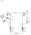
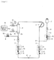
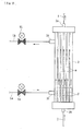
- a blood purification apparatus of a preferred embodiment of the present invention is a dialysis apparatus for performing dialysis treatment and comprises, as shown in Fig. 1 , blood circuits including an arterial blood circuit 1 and a venous blood circuit 2, a dialyzer (blood purification means) 3 interposed between the arterial blood circuit 1 and the venous blood circuit 2 for purifying blood flowing the blood circuits, a peristaltic blood pump 4 arranged on the arterial blood circuit 1, a drip chamber 5 connected to the venous blood circuit 2, a priming solution containing means 7 for containing physiological saline solution as priming solution, a priming solution supplying line Lc for connecting the priming solution containing means 7 and the arterial blood circuit 1, and a drip chamber 8 for the priming solution arranged on the priming solution supplying line Lc.
- An arterial puncture needle “a” is adapted to be connected to a tip of the arterial blood circuit 1 via a connector "c” and the peristaltic blood pump 4 is arranged on the arterial blood circuit 1.
- a venous puncture needle “b” is adapted to be connected to a tip of the venous blood circuit 2 via a connector "d” and a drip chamber 5 is arranged on the venous blood circuit 2.
- blood of a patient flows through the arterial blood circuit 1 to the dialyzer 3 and is purified by the dialyzer 3, and then is returned to the vein of a patient through the venous blood circuit 2 after having been removed air bubbles from the blood by the drip chamber 5. That is, the blood of a patient can be purified by the dialyzer 3 with being extracorporeally circulated from the tip of the arterial blood circuit 1 to the tip of the venous blood circuit 2.
- An overflow line 6 extends from the top (air layer side) of the drip chamber 5 for discharging outside solution (priming solution such as physiological saline solution) overflowed from the drip chamber 5.
- An electromagnetic valve V6 functioning as a valve means is arranged on the overflow line 6 to arbitrarily open or close the overflow line 6.
- a casing of the dialyzer 3 is provided with a blood inlet port 3a, a blood outlet port 3b, a dialysate inlet port 3c (inlet of the dialysate flow route), and a dialysate outlet port 3d (outlet of the dialysate flow route) and the arterial blood circuit 1 is connected to the blood inlet port 3a and the venous blood circuit 2 is connected to the blood outlet port 3b.
- a dialysate introducing line La and a dialysate discharging line Lb extending from a body of the dialysis apparatus are respectively connected to the dialysate inlet port 3c and the dialysate outlet port 3d.
- a large number of hollow fibers are contained in the dialyzer 3 to form blood purification membranes for purifying the blood.
- a blood flow route through which the blood of a patient flows flow route between the blood inlet port 3a and the blood outlet port 3b
- a dialysate flow route through which the dialysate flows flow route between the dialysate inlet port 3c and the dialysate outlet port 3d.
- Each hollow fiber is formed with micro apertures (pores) passing through the wall of the hollow fiber to form a hollow fiber membrane.
- a duplex pump (not shown) is arranged within the body of the dialysis apparatus with bridging the dialysate introducing line La and the dialysate discharging line Lb. Also within the body of the dialysis apparatus there is arranged a ultrafiltration pump (not shown) for removing water from the blood of a patient flowing in the dialyzer 3.
- One end of the dialysate introducing line La is connected to the dialysate inlet port 3c as described above and its other end is connected to the dialysate supplying apparatus (not shown) for preparing dialysate of predetermined concentration.
- dialysate discharging line Lb is connected to the dialysate outlet port 3d of the dialyzer 3 as described above and its other end is connected to a solution discharging means (not shown). Accordingly, the dialysate supplied from the dialysate supplying apparatus flows into the dialyzer 3 through the dialysate introducing line La and then is sent from the dialyzer 3 to the discharging means (not shown) through the dialysate discharging line Lb.
- An electromagnetic valve V4 is arranged intermediate (between the duplex pump and the dialyzer 3) of the dialysate introducing line La for opening and closing the line La
- an electromagnetic valve V5 is arranged intermediate (between the duplex pump and the dialyzer 3) of the dialysate discharging line Lb for opening and closing the line Lb.
- electromagnetic valves V1 and V2 are arranged intermediate respectively of the arterial blood circuit 1 and the venous blood circuit 2 at positions near their tips (connectors c and d) for opening and closing the circuits 1 and 2.
- an electromagnetic valve V3 is arranged intermediate of the priming solution supplying line Lc for opening and closing it.
- An arterial bubble detecting means 9 is arranged on the arterial blood circuit 1 at a position near its tip "c” for detecting bubbles existing in solution flowing the circuit 1 and a venous bubble detecting means 10 is arranged on the venous blood circuit 2 at a position near its tip “d” for detecting bubbles existing in solution flowing the circuit 2.
- reference numerals 11 and 12 denote blood discriminators arranged at positions near the tips “c” and “d” respectively of the arterial blood circuit 1 and the venous blood circuit 2
- reference numerals 13, 14 and 15 denote tube detectors arranged respectively on the arterial blood circuit 1 and the venous blood circuit 2 at positions near the tips "c” and “d” and on the priming solution supplying line Lc.
- These electromagnetic valves V1-V6 are controlled by a control means 16 such as a microcomputer for controlling opening and closing so as to open and close their related flowing lines.
- control means 16 of the present invention are electrically connected to these electromagnetic valves V1-V6 and the blood pump 4 and adapted to receive detecting signals from the venous bubbles detecting means 10 and to control them.
- the priming solution containing means (so-called “physiological saline solution bag”) 7 comprises a flexible clear container for containing a predetermined amount of the physiological saline solution (priming solution) and is suspended e.g. from a tip of a pole (not shown) projected from the body of the dialysis apparatus.
- the priming solution supplying line Lc is connected to the arterial blood circuit 1 at a position (connected portion P) between the arterial puncture needle "a” and the blood pump 4 to supply the physiological saline solution (priming solution) in the containing means 7 into the blood circuit.
- a drip chamber 8 for priming solution is connected to the priming solution supplying line Lc at intermediate thereof so that the supply (dripping) of the priming solution can be observed.
- the control means 16 can control the electromagnetic valves V1-V6 and the blood pump 4 by receiving detecting signals from the venous bubbles detecting means 10.
- the control means 16 can sequentially control following steps under a condition in which the blood inlet port 3a of the dialyzer (blood purification means) 3 is set at a top position: a priming solution pool forming step for forming a priming solution pool within the drip chamber 8, an overflowing step in which the priming solution is supplied to the drip chamber 5 from the priming solution supplying line Lc via the venous blood circuit 2 by its own weight and then discharged through the over flow line 6 by stopping the blood pump 4 and opening the electromagnetic valve (valve means) V6; a circulating step in which the priming solution is supplied to the arterial blood circuit 1 from the priming solution supplying line Lc via the venous blood circuit 2 and the dialyzer (blood purification means) 3 by driving the blood pump 4 in reverse and closing the valve
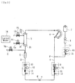
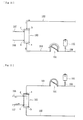
- the priming solution pool forming step (S1-S4) is performed after setting the position of the blood inlet port 3a of the dialyzer 3 upward and communicating the arterial blood circuit 1 and the venous blood circuit 2 each other by connecting the connectors "c" and "d” as shown in Fig. 2 .
- the blood pump 4 is driven in the normal direction and the physiological saline solution (priming solution) in the containing means 7 is led to the connected portion P of the artery blood circuit 1 via the priming solution supplying line Lc.
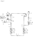
- the blood pump 4 has been rotated a predetermined number of rotation (e.g. 5 rotations) in the normal direction or not (S 2) and the blood pump 4 is rotated in the reverse direction when the predetermined number of rotation has been rotated (S 3, see Fig. 3 ). Then it is decided whether the blood pump 4 has been rotated a predetermined number of rotation (e.g. 2 rotations) in the reverse direction or not (S 4) and the blood pump 4 is stopped when the predetermined number of rotation has been rotated and a series of the priming solution pool forming steps are completed. Thus the pool of the physiological saline solution is formed in the drip chamber 8 for priming solution.
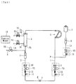
- the electromagnetic valves V2 and V3 are opened and the electromagnetic valves V1 and V4-V6 are closed.
- the physiological saline solution (priming solution) is supplied by its own weight to the drip chamber 5 from the priming solution supplying line Lc via the venous blood circuit 2 and discharged from the drip chamber 5 through the overflow line 6 by stopping the blood pump 4 and opening electromagnetic valves V6 and V1 (overflowing step S 5). That is, the physiological saline solution (priming solution) in the containing means 7 is fed by its own weight (head pressure) to the drip chamber 5 through the priming solution supplying line Lc, the connected portion P and the connector "c" on the arterial blood circuit 1 and the connector "d” on the venous blood line 2 and discharged through the overflow line 6 extending from the top of the drip chamber 5.
- the circulating step is a step in which the physiological saline solution (priming solution) is supplied to the arterial blood circuit 1 from the priming solution supplying line Lc via the venous blood circuit 2 and the dialyzer 3 with driving the blood pump 4 in the reverse direction (preferably at a driving speed of e.g. 100mL/min) and closing electromagnetic valves V6 and V3.
- the physiological saline solution can flow through the blood flow route within the dialyzer 3 from its bottom to top and accordingly the bubbles can smoothly move upward to be purged.
- This dialysate charging step S 9 is a step in which the duplex pump is driven with opening the valves V4 and V5 to charge the dialysate flow route within the dialyzer 3 with dialysate solution as shown in Fig. 7 . In this time the electromagnetic valves V3 and V6 are closed and V1, V2, V4 and V5 are opened.
- the priming solution by overflowing it from the drip chamber 5 with driving the blood pump 4 in the normal direction and opening the electromagnetic valves V3 and V6 before shifting to the dialysate charging (gas purging) step or during or after gas purging.
- the blood pump 4 may be driven during the dialysate charging (gas purging) step.
- the present invention it is possible to carry out the washing or priming of portions through which blood or dialysate can flow during the dialysis treatment and thus to positively purge bubbles therefrom by performing the priming solution pool forming step, the overflowing step, the circulating step and the dialysate charging step. Furthermore according to the present invention, since all the priming steps are performed under the condition in which the blood inlet port 3a of the dialyzer 3 is directed upward, it is possible to easily automate all the priming steps and to quickly and positively perform the air purging of the dialyzer 3.
- the venous bubble detection means 10 since it is shifted to the overflowing step by bubble detection by the venous bubble detection means 10 in the circulating step, it is possible to easily automate the priming operation and positively and smoothly perform the air bubble purging of the dialyzer (blood purification means) 3. Especially since the physiological saline solution (priming solution) is never fed to the blood flow route in the dialyzer 3 from the top to the bottom thereof in priming operation, it is possible to surely prevent the air lock which would be caused thereafter.
- the overflowing step and the circulating step are repeatedly performed until any air bubble cannot be detected by the venous bubble detecting means 10, it is possible to more positively discharge bubbles in the blood flow route during priming operation.
- the priming solution pool forming step is performed for forming the priming solution pool in the drip chamber 8 before the initial overflowing step, it is possible to form the priming solution pool in the drip chamber 8 during the priming operation.
- the priming operation can be performed under a series of controls by the control means 16, it is possible to easily automate the priming operation and thus to remarkably reduce manual operations to be performed by medical personnel. Furthermore it is possible to achieve the blood purification apparatus (dialysis apparatus) of the present invention by applying the control contents of the control means 16 to an existing blood circuit of the blood purification apparatus.
- control means 16 it is possible to construct the control means 16 so that it performs, during the priming operation, the dialysate charging step before the initial overflowing step S 5 by connecting the dialysate introducing line La and dialysate discharging line Lb respectively to the dialysate inlet port 3c and the dialysate outlet port 3b of the dialyzer (blood purification means) 3.
- Such a structure enables to prevent generation of bubbles in the priming solution since that air in the dialysate flow route moves to the blood flow route via blood purification membranes during steps from the overflowing step S 5 to the circulating steps S 7 performed thereafter.
- the dialysate introducing line La and dialysate discharging line Lb are connected to the dialyzer 3 via e.g. couplers on commencement of priming, it is possible to prevent entering of foreign matters such as dusts into the dialyzer 3 during priming operation and thus to further improve the safety in priming.
- the blood purification apparatus is modified so that dialysate charging step for charging the dialysate flow route in the dialyzer 3 with dialysate is performed by connecting the dialysate introducing line La and dialysate discharging line Lb respectively to the dialysate inlet port 3c and the dialysate outlet port 3b of the dialyzer 3 before the initial overflowing step S 5 during the priming operation as described above, the apparatus may be advantageously applied to a so-called plate type blood purification means.
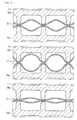
- Such a so-called plate type blood purification means has a structure as shown in Fig. 11 which has a casing 20 in which a plurality of secured plates 20a are arranged. Filtration membranes 21 of sheet configuration are sandwiched between the secured plates 20a to form blood flow routes therebetween and dialysate flow routes between the filtrating membranes 21 and the secured plates 20a.
- the plate type blood purification means comprises plurality of filtrating membranes 21 of blood purification membranes and is formed so that it has different flowing volumes between the filtrating membranes 21 in a case in which solution (priming solution or blood) flows in the blood flow route at a normal fluid pressure (see Fig. 12(a) ), a case in which solution flows at a high fluid pressure (see Fig.
- the dialysate charging step for charging the dialysate flow route in the dialyzer 3 with dialysate is performed by connecting the dialysate introducing line La and dialysate discharging line Lb respectively to the dialysate inlet port 3c and the dialysate outlet port 3b of the dialyzer 3 before the initial overflowing step S 5 during the priming operation, it is possible to prevent the charging solution in the dialysate flow route from being mingled with the priming solution due to flow of the charging solution into the blood flow route via the blood purification membranes during performing of the overflowing step S 5 through the circulating step S 7 when the apparatus is applied to a so-called wet type blood purification means in which the charging solution is previously charged in the dialyzer (blood purification means) 3.
- the control means 16 controls during the circulating step S 7 the pressure in the dialysate flow route of the dialyzer (blood purification means) 3 so that it becomes a negative pressure.
- the blood purification apparatus of the present invention since it has the ultrafiltration pump for removing water from the blood of a patient flowing through the dialyzer 3 as described above, it is possible to reduce the pressure in the dialysate flow route of the dialyzer 3 to the negative pressure by driving the ultrafiltration pump.
- the ultrafiltration pump is a pump usually formed on a line bypassed the duplex pump (driving means for supplying the dialysate) on the dialysate discharging line Lb.
- the pressure in the dialysate flow route of the dialyzer (blood purification means) 3 is reduced to the negative pressure during the circulating step S 7, it is possible to positively assure the flowing volume of the blood flow route and thus to attain a more smooth passage of the priming solution through the blood flow route.
- the so-called plate type blood purification means see Figs. 11 and 12 , it is possible to positively assure the flowing volume of the blood flow route with expanding the blood flow route between the filtration membranes 21 of sheet configuration.
- the pressure in the dialysate flow route of the dialyzer (blood purification means) 3 is reduced to the negative pressure, it is possible to eliminate any separate means for reducing the pressure in the dialysate flow route. If it is means for reducing the pressure in the dialysate flow route of the dialyzer 3 to the negative pressure during the circulating step S 7, other means (e.g. means for such as a driving source or separate and new means arranged in the blood purification apparatus) may be used. In addition it is sufficient if the pressure in the dialysate flow route in the dialyzer 3 is lower than that in the blood flow route and it is not always necessary to make the pressure negative as in this embodiment.
- the dialysis apparatus so that the blood pump 4 is driven in the normal direction by a predetermined time duration or a predetermined number of rotation after the overflowing step S 5 and before the circulating step S 7 (i.e. a time duration between the overflowing step S 5 and the circulating step S 7).
- the charging solution distilled water
- the priming solution supplied from the containing means 7 flows into the drip chamber 5 and fill this line (flow route from the blood outlet port 3b of the dialyzer 3 on the venous blood circuit 2 to the drip chamber 5) by driving the blood pump 4 relatively slowly in the normal direction at a point of time of completion of the overflowing step S 5.
- the present invention is not limited to the embodiments described above and the priming solution may be supplied without relying on its own weight in the overflowing step.
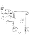
- the priming solution supplying line Ld it is possible to connect the priming solution supplying line Ld to a position between the downstream of the duplex pump 17 on the dialysate introducing line La and the upstream of the blood pump 4 on the arterial blood circuit 1.
- Fig. 9 it is possible to connect the priming solution supplying line Ld to a position between the downstream of the duplex pump 17 on the dialysate introducing line La and the upstream of the blood pump 4 on the arterial blood circuit 1.
- reference numerals 18 and V9 denote a tube detector and an electromagnetic valve on the priming solution supplying line Ld respectively
- reference characters Le and V7 denote a bypass line connecting the dialysate introducing line La and the dialysate discharging line Lb, and an electromagnetic valve on the bypassline respectively
- reference characters Lf and V8 denote a dialysate supplying line for supplying the dialysate solution to the dialysate discharging line Lb, and an electromagnetic valve on the dialysate supplying line respectively.
- Fig. 9 it is possible to supply the dialysate (priming solution) from the priming solution supplying line Ld to the drip chamber 5 via the venous blood circuit 2 and to discharge it from the overflow line 6.
- the dialysate is introduced to the side of the dialysate discharging line Lb of the duplex pump 17 via the supplying line Lf with the electromagnetic valves V4, V5 and V7 being closed and V6 and V8 being opened as shown in Fig. 9 .
- the priming solution supplying line Ld since no head is required as compared with the previous embodiment in which the priming solution is supplied using its own weight, arrangement or mounting of the priming solution supplying line Ld is not limited.
- the supplying amount of the dialysate as the priming solution can be controlled by controlling the discharging amount of the duplex pump 17, it is possible to more exactly and surely perform the overflowing step.
- the price of the dialysate is lower in general than that of the physiological saline solution, it is possible to suppress the cost of operation of the dialysis apparatus.
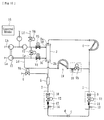
- a dialysate pump 19 (peristaltic pump same as the blood pump 4) is arranged on the priming solution supplying line Ld and the dialysate is supplied during the overflowing step by driving the dialysate pump 19.
- arrangement or mounting of the priming solution supplying line Ld is not limited.
- the supplying amount of the dialysate as the priming solution can be controlled by controlling the discharging amount of the dialysate pump 19, it is possible to more exactly and surely perform the overflowing step.
- the price of the dialysate is lower in general than that of the physiological saline solution, it is possible to suppress the cost of operation of the dialysis apparatus.
- the dialysate flow route side ⁇ can be charged with the dialysate by driving the duplex pump (not shown in Fig. 13 ) with the electromagnetic valves V4 and V5 being opened at a point of time in which a predetermined amount of the physiological saline solution (priming solution) is sent to the blood flow route ⁇ by the blood pump 4 (the priming solution is sent to the blood flow route ⁇ at an amount of about one half volume of the blood flow route ⁇ ).
- the dialysate flow route ⁇ it is performed so that the dialysate does not exceed the solution level in the blood flow route ⁇ (i.e.
- venous bubble detecting means 10 has detected bubbles or not (S8) after the charging step (S7) and it returns to the step S5 and shifts again to the overflowing step S5 when the detecting means has detected the bubbles.
- the overflowing step S5 and the circulating step S7 are repeatedly performed until the venous bubble detecting means 10 does not detect any bubble.
- the priming solution pool forming steps (S1-S4) are performed automatically, it is possible to eliminate the priming solution pool forming steps (S1-S4) or to manually perform them.
- the physiological saline solution as priming solution is supplied from the containing means 7, it is possible to supply other priming solution different from the physiological saline solution.
- the present invention is applied to the dialysis apparatus used for dialysis treatment, it may be possible to other apparatus (e.g. a blood filtrating dialysis method, a blood filtrating method, a blood purification apparatus used in AFBF, a plasma adsorption apparatus, etc.) which can purify the blood of a patient by the extracorporeally circulation.
- the present invention can be applied to any other applications if they are a blood purification apparatus and its priming method in which during the priming operation the control means can sequentially control following steps under a condition in which the blood inlet port of the blood purification means is set at a top position: an overflowing step in which the priming solution is supplied to the drip chamber from the priming solution supplying line via the venous blood circuit and then discharged through the over flow line by stopping the blood pump and opening the valve means; a circulating step in which the priming solution is supplied to the arterial blood circuit from the priming solution supplying line via the venous blood circuit and the blood purification means by driving the blood pump in reverse and closing the valve means; and a shifting step for shifting the circulating step to the overflowing step so long as the venous bubble detecting means detects bubbles.
Landscapes
- Health & Medical Sciences (AREA)
- Heart & Thoracic Surgery (AREA)
- Vascular Medicine (AREA)
- Biomedical Technology (AREA)
- Engineering & Computer Science (AREA)
- Anesthesiology (AREA)
- Cardiology (AREA)
- Hematology (AREA)
- Life Sciences & Earth Sciences (AREA)
- Animal Behavior & Ethology (AREA)
- General Health & Medical Sciences (AREA)
- Public Health (AREA)
- Veterinary Medicine (AREA)
- External Artificial Organs (AREA)
Applications Claiming Priority (4)
| Application Number | Priority Date | Filing Date | Title |
|---|---|---|---|
| JP2008319196 | 2008-12-16 | ||
| JP2009108582 | 2009-04-28 | ||
| JP2009124931A JP5294985B2 (ja) | 2008-12-16 | 2009-05-25 | 血液浄化装置及びそのプライミング方法 |
| PCT/JP2009/006897 WO2010070886A1 (ja) | 2008-12-16 | 2009-12-15 | 血液浄化装置及びそのプライミング方法 |
Publications (3)
| Publication Number | Publication Date |
|---|---|
| EP2361643A1 EP2361643A1 (en) | 2011-08-31 |
| EP2361643A4 EP2361643A4 (en) | 2015-05-20 |
| EP2361643B1 true EP2361643B1 (en) | 2016-06-01 |
Family
ID=42268566
Family Applications (1)
| Application Number | Title | Priority Date | Filing Date |
|---|---|---|---|
| EP09833194.5A Active EP2361643B1 (en) | 2008-12-16 | 2009-12-15 | Blood purifier and method of priming same |
Country Status (5)
| Country | Link |
|---|---|
| US (1) | US8343085B2 (enExample) |
| EP (1) | EP2361643B1 (enExample) |
| JP (1) | JP5294985B2 (enExample) |
| CN (1) | CN102245226B (enExample) |
| WO (1) | WO2010070886A1 (enExample) |
Cited By (2)
| Publication number | Priority date | Publication date | Assignee | Title |
|---|---|---|---|---|
| DE102020122937A1 (de) | 2020-09-02 | 2022-03-03 | B.Braun Avitum Ag | Automatisches Primen und Spülen einer extrakorporalen Blutbehandlungsvorrichtung |
| WO2022063706A1 (de) | 2020-09-28 | 2022-03-31 | B. Braun Avitum Ag | Automatisches primen einer extrakorporalen blutbehandlungsvorrichtung unter verwendung eines push-pull-verfahrens |
Families Citing this family (66)
| Publication number | Priority date | Publication date | Assignee | Title |
|---|---|---|---|---|
| US8834399B2 (en) * | 2010-12-07 | 2014-09-16 | Zoll Lifebridge Gmbh | Cardiopulmonary apparatus and methods for preserving organ viability |
| US8040493B2 (en) | 2007-10-11 | 2011-10-18 | Fresenius Medical Care Holdings, Inc. | Thermal flow meter |
| US8240636B2 (en) | 2009-01-12 | 2012-08-14 | Fresenius Medical Care Holdings, Inc. | Valve system |
| US9358331B2 (en) | 2007-09-13 | 2016-06-07 | Fresenius Medical Care Holdings, Inc. | Portable dialysis machine with improved reservoir heating system |
| US8597505B2 (en) | 2007-09-13 | 2013-12-03 | Fresenius Medical Care Holdings, Inc. | Portable dialysis machine |
| US8535522B2 (en) | 2009-02-12 | 2013-09-17 | Fresenius Medical Care Holdings, Inc. | System and method for detection of disconnection in an extracorporeal blood circuit |
| US8105487B2 (en) | 2007-09-25 | 2012-01-31 | Fresenius Medical Care Holdings, Inc. | Manifolds for use in conducting dialysis |
| US9308307B2 (en) | 2007-09-13 | 2016-04-12 | Fresenius Medical Care Holdings, Inc. | Manifold diaphragms |
| CA3057807C (en) | 2007-11-29 | 2021-04-20 | Thomas P. Robinson | System and method for conducting hemodialysis and hemofiltration |
| AU2009302327C1 (en) | 2008-10-07 | 2015-09-10 | Fresenius Medical Care Holdings, Inc. | Priming system and method for dialysis systems |
| CA2739807C (en) | 2008-10-30 | 2017-02-28 | Fresenius Medical Care Holdings, Inc. | Modular, portable dialysis system |
| WO2010114932A1 (en) | 2009-03-31 | 2010-10-07 | Xcorporeal, Inc. | Modular reservoir assembly for a hemodialysis and hemofiltration system |
| US8753515B2 (en) | 2009-12-05 | 2014-06-17 | Home Dialysis Plus, Ltd. | Dialysis system with ultrafiltration control |
| US8501009B2 (en) | 2010-06-07 | 2013-08-06 | State Of Oregon Acting By And Through The State Board Of Higher Education On Behalf Of Oregon State University | Fluid purification system |
| CN107335104A (zh) | 2010-12-07 | 2017-11-10 | 措尔生命桥梁有限责任公司 | 使过滤器逐步注满的用于体外血液治疗的装置的填充和排气的方法及系统 |
| EP2683470B1 (en) * | 2011-03-11 | 2017-05-03 | Fenwal, Inc. | Membrane separation devices, systems and methods employing same, and data management systems and methods |
| JP5699008B2 (ja) * | 2011-03-17 | 2015-04-08 | 日機装株式会社 | 血液浄化装置 |
| JP5707190B2 (ja) * | 2011-03-17 | 2015-04-22 | 日機装株式会社 | 血液浄化装置 |
| CA2851245C (en) | 2011-10-07 | 2019-11-26 | Home Dialysis Plus, Ltd. | Heat exchange fluid purification for dialysis system |
| CN104379186B (zh) * | 2012-08-09 | 2016-05-04 | 日机装株式会社 | 血液净化装置及其预充方法 |
| EP2934618B1 (en) * | 2012-12-20 | 2020-01-15 | Gambro Lundia AB | Blood set component connection detection |
| US9201036B2 (en) | 2012-12-21 | 2015-12-01 | Fresenius Medical Care Holdings, Inc. | Method and system of monitoring electrolyte levels and composition using capacitance or induction |
| US9157786B2 (en) | 2012-12-24 | 2015-10-13 | Fresenius Medical Care Holdings, Inc. | Load suspension and weighing system for a dialysis machine reservoir |
| US10022484B2 (en) | 2013-02-06 | 2018-07-17 | Nxstage Medical, Inc. | Fluid circuit priming methods, devices, and systems |
| DE102013011715A1 (de) * | 2013-07-15 | 2015-01-15 | Fresenius Medical Care Deutschland Gmbh | Verfahren zum Steuern einer Blutbehandlungsvorrichtung und Vorrichtungen |
| US9354640B2 (en) | 2013-11-11 | 2016-05-31 | Fresenius Medical Care Holdings, Inc. | Smart actuator for valve |
| JP5808062B2 (ja) * | 2013-11-11 | 2015-11-10 | 日機装株式会社 | 血液浄化装置及びそのプライミング方法 |
| JP6657186B2 (ja) | 2014-04-29 | 2020-03-04 | アウトセット・メディカル・インコーポレイテッドOutset Medical, Inc. | 透析システムおよび方法 |
| DE102014011673A1 (de) | 2014-08-05 | 2016-02-11 | Fresenius Medical Care Deutschland Gmbh | Verfahren zum Auswaschen von Gasblasen in einem extrakoporalen Blutkreislauf |
| JP6424041B2 (ja) * | 2014-08-07 | 2018-11-14 | 日機装株式会社 | 血液浄化装置 |
| JP5851003B1 (ja) | 2014-09-12 | 2016-02-03 | 日機装株式会社 | 血液浄化装置 |
| US9987411B2 (en) | 2014-12-19 | 2018-06-05 | Fenwal, Inc. | Methods and systems for priming a biological fluid processing circuit |
| JP6517023B2 (ja) | 2015-01-23 | 2019-05-22 | 日機装株式会社 | 血液浄化装置 |
| EP3295976B1 (en) | 2015-05-12 | 2021-08-04 | Nikkiso Co., Ltd. | Blood purification device and priming method |
| JP6516559B2 (ja) | 2015-05-21 | 2019-05-22 | 日機装株式会社 | 血液浄化装置 |
| JP6613062B2 (ja) | 2015-06-24 | 2019-11-27 | 日機装株式会社 | 血液浄化装置及び血液浄化システム |
| WO2016208705A1 (ja) | 2015-06-24 | 2016-12-29 | 日機装株式会社 | 血液浄化装置 |
| CN105477708A (zh) * | 2015-08-08 | 2016-04-13 | 常州华岳微创医疗器械有限公司 | 一种可装卸管路的血液净化装置 |
| JP6636770B2 (ja) * | 2015-10-30 | 2020-01-29 | 日機装株式会社 | 血液浄化装置 |
| JP6111351B1 (ja) | 2016-01-25 | 2017-04-05 | 日機装株式会社 | 血液浄化装置 |
| CN113304341B (zh) * | 2016-03-31 | 2024-05-14 | 旭化成医疗株式会社 | 血液净化系统和其启动加注方法 |
| JP6762772B2 (ja) * | 2016-06-08 | 2020-09-30 | 日機装株式会社 | 血液浄化装置及びその接続確認方法 |
| CN106215265B (zh) * | 2016-08-16 | 2018-09-11 | 珠海健帆生物科技股份有限公司 | 血液净化器排气方法 |
| WO2018035520A1 (en) | 2016-08-19 | 2018-02-22 | Outset Medical, Inc. | Peritoneal dialysis system and methods |
| JP6998112B2 (ja) | 2016-09-12 | 2022-01-18 | 日機装株式会社 | 血液浄化装置 |
| JP6826852B2 (ja) | 2016-09-23 | 2021-02-10 | 日機装株式会社 | 血液浄化装置 |
| CN108114334B (zh) * | 2016-11-28 | 2024-01-12 | 健帆生物科技集团股份有限公司 | 血液净化器、血液净化系统及其预冲方法 |
| EP3603695B1 (en) * | 2017-03-31 | 2021-04-07 | Asahi Kasei Medical Co., Ltd. | Blood purification device and priming method thereof |
| WO2018186495A1 (ja) | 2017-04-07 | 2018-10-11 | 株式会社アルチザンラボ | 注射針用キャップ及び透析回路プライミング用デバイス |
| US11420037B2 (en) * | 2017-08-04 | 2022-08-23 | Fresenius Medical Care Holdings, Inc. | Infusion methods for extracoporeal systems |
| JP6462077B1 (ja) | 2017-09-07 | 2019-01-30 | 日機装株式会社 | 血液浄化装置及びその気泡の排出方法 |
| JP6464238B1 (ja) | 2017-09-07 | 2019-02-06 | 日機装株式会社 | 血液浄化装置及びその気泡の排出方法 |
| JP7317008B2 (ja) * | 2017-12-21 | 2023-07-28 | ガンブロ・ルンディア・エービー | 二酸化炭素生成及びプライムを有する透析システム |
| EP3505200B1 (en) | 2017-12-29 | 2020-09-09 | Gambro Lundia AB | Apparatus for extracorporeal blood treatment |
| JP6488048B2 (ja) * | 2018-05-24 | 2019-03-20 | 日機装株式会社 | 血液浄化装置 |
| ES3028957T3 (en) | 2018-08-23 | 2025-06-20 | Outset Medical Inc | Dialysis system and methods |
| CN113795286A (zh) | 2019-04-30 | 2021-12-14 | 开端医疗公司 | 透析系统和方法 |
| EP3991764B1 (en) | 2020-10-27 | 2024-03-06 | Bellco S.r.l. | Flowmeter for proportioning water in dialysis system |
| US12318528B2 (en) | 2020-10-30 | 2025-06-03 | Mozarc Medical Us Llc | Variable orifice fistula graft |
| EP3991770B1 (en) | 2020-10-30 | 2024-10-30 | Bellco S.r.l. | Dialysis cassette with pump features |
| EP4008376A1 (en) | 2020-12-03 | 2022-06-08 | Medtronic, Inc. | Flexible tube routing accessory for peritoneal dialysis system |
| US11904281B2 (en) | 2021-02-11 | 2024-02-20 | Fenwal, Inc. | Spinning membrane separator priming systems and methods |
| CN114344596B (zh) * | 2021-12-27 | 2023-07-25 | 健帆生物科技集团股份有限公司 | 血液灌流器的排气控制系统 |
| CN114209906A (zh) * | 2022-01-04 | 2022-03-22 | 山东威高血液净化制品股份有限公司 | 一种测试血室压力降的自动化装置和方法 |
| CN119236210B (zh) * | 2024-08-29 | 2025-09-23 | 健帆生物科技集团股份有限公司 | 血液净化设备的泵秤联合校准控制方法、血液净化设备及存储介质 |
| CN119680040B (zh) * | 2024-12-03 | 2025-11-14 | 中国人民解放军空军军医大学 | 适用于院外应急救援的ecmo快速预充系统及使用方法 |
Family Cites Families (9)
| Publication number | Priority date | Publication date | Assignee | Title |
|---|---|---|---|---|
| JP2659914B2 (ja) * | 1994-07-29 | 1997-09-30 | 日機装株式会社 | 血液浄化回路の自動プライミング処理方法および装置 |
| US5951870A (en) * | 1997-10-21 | 1999-09-14 | Dsu Medical Corporation | Automatic priming of blood sets |
| JP2000093449A (ja) | 1998-09-24 | 2000-04-04 | Nikkiso Co Ltd | 加温冷却自在型chdf装置 |
| JP3937436B2 (ja) * | 2003-06-05 | 2007-06-27 | ニプロ株式会社 | 血液浄化装置および血液回路の自動プライミング方法 |
| JP4433717B2 (ja) * | 2003-07-30 | 2010-03-17 | 株式会社ジェイ・エム・エス | 気泡検出システム、該気泡検出システムを備えた血液透析回路 |
| JP4899866B2 (ja) | 2005-01-07 | 2012-03-21 | 株式会社ジェイ・エム・エス | 自動プライミング方法 |
| JP4798653B2 (ja) * | 2005-11-18 | 2011-10-19 | 日機装株式会社 | 血液浄化装置 |
| JP4613831B2 (ja) * | 2006-01-17 | 2011-01-19 | ニプロ株式会社 | 血液浄化装置及びその血液循環路の自動プライミング方法 |
| JP4853956B2 (ja) * | 2006-04-05 | 2012-01-11 | 日機装株式会社 | 血液回路のプライミング方法 |
-
2009
- 2009-05-25 JP JP2009124931A patent/JP5294985B2/ja active Active
- 2009-12-15 CN CN200980150387.6A patent/CN102245226B/zh active Active
- 2009-12-15 US US12/680,298 patent/US8343085B2/en active Active
- 2009-12-15 EP EP09833194.5A patent/EP2361643B1/en active Active
- 2009-12-15 WO PCT/JP2009/006897 patent/WO2010070886A1/ja not_active Ceased
Cited By (6)
| Publication number | Priority date | Publication date | Assignee | Title |
|---|---|---|---|---|
| DE102020122937A1 (de) | 2020-09-02 | 2022-03-03 | B.Braun Avitum Ag | Automatisches Primen und Spülen einer extrakorporalen Blutbehandlungsvorrichtung |
| WO2022048955A1 (de) | 2020-09-02 | 2022-03-10 | B. Braun Avitum Ag | Automatisches primen und spülen einer extrakorporalen blutbehandlungsvorrichtung |
| US12290623B2 (en) | 2020-09-02 | 2025-05-06 | B. Braun Avitum Ag | Automatic priming and rinsing of an extracorporeal blood treatment apparatus |
| WO2022063706A1 (de) | 2020-09-28 | 2022-03-31 | B. Braun Avitum Ag | Automatisches primen einer extrakorporalen blutbehandlungsvorrichtung unter verwendung eines push-pull-verfahrens |
| DE102020125291A1 (de) | 2020-09-28 | 2022-03-31 | B.Braun Avitum Ag | Automatisches Primen einer extrakorporalen Blutbehandlungsvorrichtung unter Verwendung eines Push-Pull-Verfahrens |
| US12280193B2 (en) | 2020-09-28 | 2025-04-22 | B. Braun Avitum Ag | Automatic priming of an extracorporeal blood treatment device using a push-pull method |
Also Published As
| Publication number | Publication date |
|---|---|
| JP5294985B2 (ja) | 2013-09-18 |
| EP2361643A4 (en) | 2015-05-20 |
| JP2010273693A (ja) | 2010-12-09 |
| WO2010070886A1 (ja) | 2010-06-24 |
| CN102245226A (zh) | 2011-11-16 |
| EP2361643A1 (en) | 2011-08-31 |
| US20110213289A1 (en) | 2011-09-01 |
| US8343085B2 (en) | 2013-01-01 |
| CN102245226B (zh) | 2014-03-05 |
Similar Documents
| Publication | Publication Date | Title |
|---|---|---|
| EP2361643B1 (en) | Blood purifier and method of priming same | |
| US10195336B2 (en) | Blood purification apparatus and priming method thereof | |
| CN101309710B (zh) | 血液净化装置和其穿刺针的连接状态判断方法 | |
| US20090312686A1 (en) | Blood purification apparatus and priming method thereof | |
| EP2883558B1 (en) | Blood purification device and priming method therefor | |
| CA2683051C (en) | Method and apparatus for priming an extracorporeal blood circuit | |
| JP5247864B2 (ja) | 血液浄化装置 | |
| CN103732270B (zh) | 血液净化装置 | |
| CN110494174A (zh) | 血液透析装置中补充液管线与血液回路的连接状态的判定方法及判定装置 | |
| JP2011110098A (ja) | 血液浄化装置 | |
| WO2006054367A1 (ja) | 自動返血装置 | |
| JP2013048803A (ja) | 血液浄化装置 | |
| US11406747B2 (en) | Extracorporeal circulation apparatus and method of discharging bubbles therefrom | |
| JP2010253130A (ja) | 血液浄化装置及びその気泡除去方法 | |
| CN108348672B (zh) | 血液净化装置 | |
| JP2011136003A (ja) | 血液浄化装置及びそのプライミング方法 | |
| US20200206407A1 (en) | Blood Purification Apparatus and Method of Discharging Bubbles Therefrom | |
| JP5192241B2 (ja) | 血液浄化装置及びそのプライミング方法 | |
| JP7293761B2 (ja) | 透析装置及び回路セットの判定方法 | |
| JP2009153640A (ja) | 血液浄化装置及びそのプライミング方法 |
Legal Events
| Date | Code | Title | Description |
|---|---|---|---|
| PUAI | Public reference made under article 153(3) epc to a published international application that has entered the european phase |
Free format text: ORIGINAL CODE: 0009012 |
|
| 17P | Request for examination filed |
Effective date: 20110622 |
|
| AK | Designated contracting states |
Kind code of ref document: A1 Designated state(s): AT BE BG CH CY CZ DE DK EE ES FI FR GB GR HR HU IE IS IT LI LT LU LV MC MK MT NL NO PL PT RO SE SI SK SM TR |
|
| DAX | Request for extension of the european patent (deleted) | ||
| RA4 | Supplementary search report drawn up and despatched (corrected) |
Effective date: 20150422 |
|
| RIC1 | Information provided on ipc code assigned before grant |
Ipc: A61M 1/36 20060101ALI20150416BHEP Ipc: A61M 1/14 20060101AFI20150416BHEP |
|
| GRAP | Despatch of communication of intention to grant a patent |
Free format text: ORIGINAL CODE: EPIDOSNIGR1 |
|
| RIC1 | Information provided on ipc code assigned before grant |
Ipc: A61M 1/14 20060101AFI20160106BHEP Ipc: A61M 1/36 20060101ALI20160106BHEP |
|
| INTG | Intention to grant announced |
Effective date: 20160127 |
|
| GRAS | Grant fee paid |
Free format text: ORIGINAL CODE: EPIDOSNIGR3 |
|
| GRAA | (expected) grant |
Free format text: ORIGINAL CODE: 0009210 |
|
| AK | Designated contracting states |
Kind code of ref document: B1 Designated state(s): AT BE BG CH CY CZ DE DK EE ES FI FR GB GR HR HU IE IS IT LI LT LU LV MC MK MT NL NO PL PT RO SE SI SK SM TR |
|
| REG | Reference to a national code |
Ref country code: GB Ref legal event code: FG4D |
|
| REG | Reference to a national code |
Ref country code: CH Ref legal event code: EP Ref country code: AT Ref legal event code: REF Ref document number: 803473 Country of ref document: AT Kind code of ref document: T Effective date: 20160615 |
|
| REG | Reference to a national code |
Ref country code: IE Ref legal event code: FG4D |
|
| REG | Reference to a national code |
Ref country code: DE Ref legal event code: R096 Ref document number: 602009039064 Country of ref document: DE |
|
| REG | Reference to a national code |
Ref country code: SE Ref legal event code: TRGR |
|
| REG | Reference to a national code |
Ref country code: LT Ref legal event code: MG4D |
|
| REG | Reference to a national code |
Ref country code: NL Ref legal event code: MP Effective date: 20160601 |
|
| PG25 | Lapsed in a contracting state [announced via postgrant information from national office to epo] |
Ref country code: FI Free format text: LAPSE BECAUSE OF FAILURE TO SUBMIT A TRANSLATION OF THE DESCRIPTION OR TO PAY THE FEE WITHIN THE PRESCRIBED TIME-LIMIT Effective date: 20160601 Ref country code: LT Free format text: LAPSE BECAUSE OF FAILURE TO SUBMIT A TRANSLATION OF THE DESCRIPTION OR TO PAY THE FEE WITHIN THE PRESCRIBED TIME-LIMIT Effective date: 20160601 Ref country code: NO Free format text: LAPSE BECAUSE OF FAILURE TO SUBMIT A TRANSLATION OF THE DESCRIPTION OR TO PAY THE FEE WITHIN THE PRESCRIBED TIME-LIMIT Effective date: 20160901 |
|
| REG | Reference to a national code |
Ref country code: AT Ref legal event code: MK05 Ref document number: 803473 Country of ref document: AT Kind code of ref document: T Effective date: 20160601 |
|
| PG25 | Lapsed in a contracting state [announced via postgrant information from national office to epo] |
Ref country code: LV Free format text: LAPSE BECAUSE OF FAILURE TO SUBMIT A TRANSLATION OF THE DESCRIPTION OR TO PAY THE FEE WITHIN THE PRESCRIBED TIME-LIMIT Effective date: 20160601 Ref country code: ES Free format text: LAPSE BECAUSE OF FAILURE TO SUBMIT A TRANSLATION OF THE DESCRIPTION OR TO PAY THE FEE WITHIN THE PRESCRIBED TIME-LIMIT Effective date: 20160601 Ref country code: GR Free format text: LAPSE BECAUSE OF FAILURE TO SUBMIT A TRANSLATION OF THE DESCRIPTION OR TO PAY THE FEE WITHIN THE PRESCRIBED TIME-LIMIT Effective date: 20160902 Ref country code: NL Free format text: LAPSE BECAUSE OF FAILURE TO SUBMIT A TRANSLATION OF THE DESCRIPTION OR TO PAY THE FEE WITHIN THE PRESCRIBED TIME-LIMIT Effective date: 20160601 Ref country code: HR Free format text: LAPSE BECAUSE OF FAILURE TO SUBMIT A TRANSLATION OF THE DESCRIPTION OR TO PAY THE FEE WITHIN THE PRESCRIBED TIME-LIMIT Effective date: 20160601 |
|
| REG | Reference to a national code |
Ref country code: FR Ref legal event code: PLFP Year of fee payment: 8 |
|
| PG25 | Lapsed in a contracting state [announced via postgrant information from national office to epo] |
Ref country code: CZ Free format text: LAPSE BECAUSE OF FAILURE TO SUBMIT A TRANSLATION OF THE DESCRIPTION OR TO PAY THE FEE WITHIN THE PRESCRIBED TIME-LIMIT Effective date: 20160601 Ref country code: IS Free format text: LAPSE BECAUSE OF FAILURE TO SUBMIT A TRANSLATION OF THE DESCRIPTION OR TO PAY THE FEE WITHIN THE PRESCRIBED TIME-LIMIT Effective date: 20161001 Ref country code: EE Free format text: LAPSE BECAUSE OF FAILURE TO SUBMIT A TRANSLATION OF THE DESCRIPTION OR TO PAY THE FEE WITHIN THE PRESCRIBED TIME-LIMIT Effective date: 20160601 Ref country code: SK Free format text: LAPSE BECAUSE OF FAILURE TO SUBMIT A TRANSLATION OF THE DESCRIPTION OR TO PAY THE FEE WITHIN THE PRESCRIBED TIME-LIMIT Effective date: 20160601 Ref country code: RO Free format text: LAPSE BECAUSE OF FAILURE TO SUBMIT A TRANSLATION OF THE DESCRIPTION OR TO PAY THE FEE WITHIN THE PRESCRIBED TIME-LIMIT Effective date: 20160601 |
|
| PG25 | Lapsed in a contracting state [announced via postgrant information from national office to epo] |
Ref country code: AT Free format text: LAPSE BECAUSE OF FAILURE TO SUBMIT A TRANSLATION OF THE DESCRIPTION OR TO PAY THE FEE WITHIN THE PRESCRIBED TIME-LIMIT Effective date: 20160601 Ref country code: PT Free format text: LAPSE BECAUSE OF FAILURE TO SUBMIT A TRANSLATION OF THE DESCRIPTION OR TO PAY THE FEE WITHIN THE PRESCRIBED TIME-LIMIT Effective date: 20161003 Ref country code: PL Free format text: LAPSE BECAUSE OF FAILURE TO SUBMIT A TRANSLATION OF THE DESCRIPTION OR TO PAY THE FEE WITHIN THE PRESCRIBED TIME-LIMIT Effective date: 20160601 Ref country code: BE Free format text: LAPSE BECAUSE OF FAILURE TO SUBMIT A TRANSLATION OF THE DESCRIPTION OR TO PAY THE FEE WITHIN THE PRESCRIBED TIME-LIMIT Effective date: 20160601 Ref country code: SM Free format text: LAPSE BECAUSE OF FAILURE TO SUBMIT A TRANSLATION OF THE DESCRIPTION OR TO PAY THE FEE WITHIN THE PRESCRIBED TIME-LIMIT Effective date: 20160601 |
|
| REG | Reference to a national code |
Ref country code: DE Ref legal event code: R097 Ref document number: 602009039064 Country of ref document: DE |
|
| PLBE | No opposition filed within time limit |
Free format text: ORIGINAL CODE: 0009261 |
|
| STAA | Information on the status of an ep patent application or granted ep patent |
Free format text: STATUS: NO OPPOSITION FILED WITHIN TIME LIMIT |
|
| 26N | No opposition filed |
Effective date: 20170302 |
|
| PG25 | Lapsed in a contracting state [announced via postgrant information from national office to epo] |
Ref country code: SI Free format text: LAPSE BECAUSE OF FAILURE TO SUBMIT A TRANSLATION OF THE DESCRIPTION OR TO PAY THE FEE WITHIN THE PRESCRIBED TIME-LIMIT Effective date: 20160601 Ref country code: DK Free format text: LAPSE BECAUSE OF FAILURE TO SUBMIT A TRANSLATION OF THE DESCRIPTION OR TO PAY THE FEE WITHIN THE PRESCRIBED TIME-LIMIT Effective date: 20160601 |
|
| REG | Reference to a national code |
Ref country code: CH Ref legal event code: PL |
|
| PG25 | Lapsed in a contracting state [announced via postgrant information from national office to epo] |
Ref country code: MC Free format text: LAPSE BECAUSE OF FAILURE TO SUBMIT A TRANSLATION OF THE DESCRIPTION OR TO PAY THE FEE WITHIN THE PRESCRIBED TIME-LIMIT Effective date: 20160601 |
|
| REG | Reference to a national code |
Ref country code: IE Ref legal event code: MM4A |
|
| PG25 | Lapsed in a contracting state [announced via postgrant information from national office to epo] |
Ref country code: LI Free format text: LAPSE BECAUSE OF NON-PAYMENT OF DUE FEES Effective date: 20161231 Ref country code: CH Free format text: LAPSE BECAUSE OF NON-PAYMENT OF DUE FEES Effective date: 20161231 Ref country code: LU Free format text: LAPSE BECAUSE OF NON-PAYMENT OF DUE FEES Effective date: 20161215 |
|
| PG25 | Lapsed in a contracting state [announced via postgrant information from national office to epo] |
Ref country code: IE Free format text: LAPSE BECAUSE OF NON-PAYMENT OF DUE FEES Effective date: 20161215 |
|
| REG | Reference to a national code |
Ref country code: FR Ref legal event code: PLFP Year of fee payment: 9 |
|
| PG25 | Lapsed in a contracting state [announced via postgrant information from national office to epo] |
Ref country code: CY Free format text: LAPSE BECAUSE OF FAILURE TO SUBMIT A TRANSLATION OF THE DESCRIPTION OR TO PAY THE FEE WITHIN THE PRESCRIBED TIME-LIMIT Effective date: 20160601 Ref country code: HU Free format text: LAPSE BECAUSE OF FAILURE TO SUBMIT A TRANSLATION OF THE DESCRIPTION OR TO PAY THE FEE WITHIN THE PRESCRIBED TIME-LIMIT; INVALID AB INITIO Effective date: 20091215 |
|
| PG25 | Lapsed in a contracting state [announced via postgrant information from national office to epo] |
Ref country code: MK Free format text: LAPSE BECAUSE OF FAILURE TO SUBMIT A TRANSLATION OF THE DESCRIPTION OR TO PAY THE FEE WITHIN THE PRESCRIBED TIME-LIMIT Effective date: 20160601 Ref country code: TR Free format text: LAPSE BECAUSE OF FAILURE TO SUBMIT A TRANSLATION OF THE DESCRIPTION OR TO PAY THE FEE WITHIN THE PRESCRIBED TIME-LIMIT Effective date: 20160601 |
|
| PG25 | Lapsed in a contracting state [announced via postgrant information from national office to epo] |
Ref country code: BG Free format text: LAPSE BECAUSE OF FAILURE TO SUBMIT A TRANSLATION OF THE DESCRIPTION OR TO PAY THE FEE WITHIN THE PRESCRIBED TIME-LIMIT Effective date: 20160601 |
|
| PG25 | Lapsed in a contracting state [announced via postgrant information from national office to epo] |
Ref country code: MT Free format text: LAPSE BECAUSE OF NON-PAYMENT OF DUE FEES Effective date: 20161215 |
|
| P01 | Opt-out of the competence of the unified patent court (upc) registered |
Effective date: 20230523 |
|
| PGFP | Annual fee paid to national office [announced via postgrant information from national office to epo] |
Ref country code: DE Payment date: 20251211 Year of fee payment: 17 |
|
| PGFP | Annual fee paid to national office [announced via postgrant information from national office to epo] |
Ref country code: GB Payment date: 20251219 Year of fee payment: 17 |
|
| PGFP | Annual fee paid to national office [announced via postgrant information from national office to epo] |
Ref country code: IT Payment date: 20251223 Year of fee payment: 17 |
|
| PGFP | Annual fee paid to national office [announced via postgrant information from national office to epo] |
Ref country code: FR Payment date: 20251222 Year of fee payment: 17 |
|
| PGFP | Annual fee paid to national office [announced via postgrant information from national office to epo] |
Ref country code: SE Payment date: 20251219 Year of fee payment: 17 |