WO2010064704A1 - マイクロホンユニット - Google Patents
マイクロホンユニット Download PDFInfo
- Publication number
- WO2010064704A1 WO2010064704A1 PCT/JP2009/070388 JP2009070388W WO2010064704A1 WO 2010064704 A1 WO2010064704 A1 WO 2010064704A1 JP 2009070388 W JP2009070388 W JP 2009070388W WO 2010064704 A1 WO2010064704 A1 WO 2010064704A1
- Authority
- WO
- WIPO (PCT)
- Prior art keywords
- sound
- diaphragm
- microphone unit
- resonance frequency
- introduction space
- Prior art date
Links
Images


Classifications
-
- H—ELECTRICITY
- H04—ELECTRIC COMMUNICATION TECHNIQUE
- H04R—LOUDSPEAKERS, MICROPHONES, GRAMOPHONE PICK-UPS OR LIKE ACOUSTIC ELECTROMECHANICAL TRANSDUCERS; DEAF-AID SETS; PUBLIC ADDRESS SYSTEMS
- H04R1/00—Details of transducers, loudspeakers or microphones
- H04R1/20—Arrangements for obtaining desired frequency or directional characteristics
- H04R1/32—Arrangements for obtaining desired frequency or directional characteristics for obtaining desired directional characteristic only
- H04R1/34—Arrangements for obtaining desired frequency or directional characteristics for obtaining desired directional characteristic only by using a single transducer with sound reflecting, diffracting, directing or guiding means
- H04R1/38—Arrangements for obtaining desired frequency or directional characteristics for obtaining desired directional characteristic only by using a single transducer with sound reflecting, diffracting, directing or guiding means in which sound waves act upon both sides of a diaphragm and incorporating acoustic phase-shifting means, e.g. pressure-gradient microphone
-
- H—ELECTRICITY
- H04—ELECTRIC COMMUNICATION TECHNIQUE
- H04R—LOUDSPEAKERS, MICROPHONES, GRAMOPHONE PICK-UPS OR LIKE ACOUSTIC ELECTROMECHANICAL TRANSDUCERS; DEAF-AID SETS; PUBLIC ADDRESS SYSTEMS
- H04R19/00—Electrostatic transducers
- H04R19/04—Microphones
-
- H—ELECTRICITY
- H04—ELECTRIC COMMUNICATION TECHNIQUE
- H04R—LOUDSPEAKERS, MICROPHONES, GRAMOPHONE PICK-UPS OR LIKE ACOUSTIC ELECTROMECHANICAL TRANSDUCERS; DEAF-AID SETS; PUBLIC ADDRESS SYSTEMS
- H04R2499/00—Aspects covered by H04R or H04S not otherwise provided for in their subgroups
- H04R2499/10—General applications
- H04R2499/11—Transducers incorporated or for use in hand-held devices, e.g. mobile phones, PDA's, camera's
Definitions
- the present invention relates to a microphone unit that converts an input sound into an electric signal.
- the microphone unit is formed so that sound pressure is applied to both surfaces (front and rear surfaces) of the diaphragm, and uses vibration of the diaphragm based on the sound pressure difference.
- the present invention relates to a configuration of a microphone unit that converts input sound into an electric signal.
- a microphone unit is provided in a voice communication device such as a mobile phone or a transceiver, an information processing system using a technique for analyzing input voice such as a voice authentication system, or a recording device.
- a voice communication device such as a mobile phone or a transceiver
- an information processing system using a technique for analyzing input voice such as a voice authentication system, or a recording device.
- a microphone unit directivity As a technique for removing only noise and collecting only the target voice in a usage environment where noise exists, giving a microphone unit directivity can be mentioned.
- a microphone unit having directivity a microphone unit that is formed so that sound pressure is applied to both surfaces of a diaphragm (diaphragm) and that converts input sound into an electrical signal using vibration of the diaphragm based on the sound pressure difference is provided. Conventionally known (see, for example, Patent Document 1).
- the microphone unit which is formed so that sound pressure is applied to both surfaces of the diaphragm and converts the input sound into an electrical signal using the vibration of the diaphragm based on the sound pressure difference, applies sound pressure only to one surface of the diaphragm. Therefore, the displacement due to vibration of the diaphragm is smaller than that of the microphone unit that vibrates the diaphragm. For this reason, the microphone unit formed so that sound pressure is applied to both surfaces of the diaphragm described above may not be able to obtain a desired SNR (Signal to Noise Ratio), and can be improved to ensure a high SNR. It was sought after.
- SNR Synignal to Noise Ratio
- an object of the present invention is a microphone unit which is formed so that sound pressure is applied to both surfaces of a diaphragm and converts input sound into an electric signal using vibration of the diaphragm based on the sound pressure difference, and has a high SNR. It is to provide a high-performance microphone unit that can ensure the above.
- a microphone unit of the present invention includes a housing, a diaphragm disposed inside the housing, and an electric circuit unit that processes an electric signal generated based on vibration of the diaphragm.
- a second sound introduction space that guides sound outside the housing to a second surface that is the back surface of the first surface of the diaphragm through a hole, and a resonance frequency of the diaphragm is It is set within a range of ⁇ 4 kHz with respect to at least one resonance frequency of the first sound guide space and the second sound guide space.
- the microphone unit of this configuration is formed so that sound pressure is applied to both surfaces of the diaphragm, and is configured to convert the input sound into an electrical signal using the vibration of the diaphragm based on the sound pressure difference.
- the sound pressure exerted by the sound wave from the first sound hole on the diaphragm and the sound pressure exerted by the sound wave from the second sound hole on the diaphragm are: It is necessary to increase the sound pressure difference. In this case, the space between the first sound hole and the second sound hole must be increased to increase the volume of the first sound introduction space and the second sound introduction space. The resonance frequency cannot be sufficiently high.
- the resonance frequency of the diaphragm is lowered by the idea of reversing the conventional method. It is configured to be close to the resonance frequency. For this reason, according to this configuration, it is possible to provide a high-performance microphone unit that can increase the sensitivity by lowering the stiffness of the diaphragm and ensure a high SNR.
- the first sound hole and the second sound hole are formed in the same plane, and the distance between the centers of the first sound hole and the second sound hole is 4 mm or more and 6 mm or less. Is preferred.
- the resonance frequencies of the first sound introduction space and the second sound introduction space are substantially the same. With this configuration, it is easy to obtain a microphone unit with a high SNR.
- the resonance frequency of at least one of the first sound guide space and the second sound guide space is 10 kHz or more and 12 kHz or less. This configuration is preferable because the adverse effect on the frequency characteristics of the microphone unit due to resonance of the sound guide space can be suppressed as much as possible.
- the resonance frequency of the diaphragm may be set to be substantially the same as the resonance frequency of at least one of the first sound introduction space and the second sound introduction space.
- a high SNR is ensured for a microphone unit that is formed so that sound pressure is applied to both surfaces of a diaphragm and that converts input sound into an electrical signal using vibration of the diaphragm based on the sound pressure difference.
- a high-performance microphone unit can be provided.
- the schematic perspective view which shows the structure of the microphone unit of this embodiment.
- Schematic cross-sectional view at the AA position in FIG. Schematic sectional view showing the configuration of a MEMS chip provided in the microphone unit of the present embodiment
- Diagram for explaining the attenuation characteristics of sound waves The figure for demonstrating the design method of the diaphragm in the conventional microphone unit Diagram for explaining frequency characteristics of sound guide space
- the figure for explaining the frequency characteristic of the microphone unit The figure which shows the frequency characteristic at the time of setting the resonance frequency fd of a diaphragm to about 4 kHz higher than the resonance frequency f1 of 1st sound introduction space in the microphone unit of this embodiment.
- the figure which shows the frequency characteristic at the time of setting the resonance frequency fd of a diaphragm to the resonance frequency f1 of 1st sound introduction space in the microphone unit of this embodiment substantially the same.
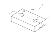
- FIG. 1 is a schematic perspective view showing the configuration of the microphone unit of the present embodiment.
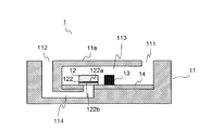
- FIG. 2 is a schematic cross-sectional view at the position AA in FIG.
- the microphone unit 1 of the present embodiment includes a housing 11, a MEMS (Micro Electro Mechanical System) chip 12, an ASIC (Application Specific Integrated Circuit) 13, a circuit board 14, Is provided.
- MEMS Micro Electro Mechanical System
- ASIC Application Specific Integrated Circuit
- the housing 11 is formed in a substantially rectangular parallelepiped shape, and accommodates the MEMS chip 12 including the diaphragm (diaphragm) 122, the ASIC 13, and the circuit board 14 therein.
- the outer shape of the housing 11 is not limited to the shape of the present embodiment, and may be, for example, a cube, and is not limited to a hexahedron such as a rectangular parallelepiped or a cube, but a polyhedral structure other than a hexahedron or other than a polyhedron. (For example, a spherical structure, a hemispherical structure, etc.).
- the housing 11 has a first sound introduction space 113 and a second sound introduction space 114 formed therein.
- the first sound guide space 113 and the second sound guide space 114 are divided by a diaphragm 122 included in the MEMS chip 12 described later in detail. That is, the first sound introduction space 113 is in contact with the upper surface (first surface) 122a side of the vibration membrane 122, and the second sound introduction space 114 is in contact with the lower surface (second surface) 122b side of the vibration membrane 122. It has become.
- a first sound hole 111 and a second sound hole 112 having a substantially circular shape in plan view are formed on the upper surface 11a of the housing 11.
- the first sound hole 111 is connected to the first sound guide space 113, so that the first sound guide space 113 and the external space of the housing 11 are connected. That is, sound outside the housing 11 is guided to the upper surface 122 a of the vibrating membrane 122 by the first sound introduction space 113 through the first sound hole 111.
- the second sound hole 112 is connected to the second sound guide space 114, whereby the second sound guide space 114 and the external space of the housing 11 are connected. That is, sound outside the housing 11 is guided to the lower surface 122 b of the diaphragm 122 by the second sound introduction space 114 through the second sound hole 112.
- the distance from the first sound hole 111 to the diaphragm 122 through the first sound guide space 113 is equal to the distance from the second sound hole 112 to the diaphragm 122 through the second sound guide space 114. Yes.
- the center-to-center distance between the first sound hole 111 and the second sound hole 112 is preferably about 4 to 6 mm, and more preferably about 5 mm.
- the first sound hole 111 and the second sound hole 112 have a substantially circular shape in plan view.
- the shape is not limited to this, and the shape may be other than a circular shape, for example, a rectangular shape. Etc.
- the first sound hole 111 and the second sound hole 112 are each one, but the present invention is not limited to this configuration, and the number of each may be plural.
- the first sound hole 111 and the second sound hole 112 are formed on the same surface of the housing 11, but the present invention is not limited to this configuration, and the first sound hole 111 and the second sound hole 112 may be formed on different surfaces. For example, it is good also as a structure formed in an adjacent surface and the surface which opposes.
- the sound path in the voice input device for example, a mobile phone or the like
- the microphone unit 1 of the present embodiment is such that the two sound holes 111 and 112 are formed on the same surface of the housing 11 as in the present embodiment. Is preferable in that it is not complicated.
- FIG. 3 is a schematic cross-sectional view showing the configuration of the MEMS chip 12 included in the microphone unit 1 of the present embodiment.
- the MEMS chip 12 includes an insulating base substrate 121, a vibration film 122, an insulating film 123, and a fixed electrode 124, and forms a capacitor type microphone.
- the MEMS chip 12 is manufactured using a semiconductor manufacturing technique.
- an opening 121 a having a substantially circular shape in plan view is formed in the base substrate 121, so that sound waves coming from the lower side of the vibration film 122 reach the vibration film 122.
- the vibration film 122 formed on the base substrate 121 is a thin film that vibrates (vibrates in the vertical direction) in response to sound waves, has conductivity, and forms one end of the electrode.
- the fixed electrode 124 is disposed so as to face the vibration film 122 with the insulating film 123 interposed therebetween. Thereby, the vibrating membrane 122 and the fixed electrode 124 form a capacitance. Note that a plurality of sound holes 124 a are formed in the fixed electrode 124 so that sound waves can pass, and sound waves coming from the upper side of the vibration film 122 reach the vibration film 122.
- the vibrating membrane 122 is below the fixed electrode 124, but is configured to have an opposite relationship (relationship in which the vibrating membrane is above and the fixed electrode is below). It doesn't matter.
- FIG. 4 is a diagram for explaining a circuit configuration of the ASIC 13 provided in the microphone unit 1 of the present embodiment.
- the ASIC 13 is an embodiment of the electric circuit unit of the present invention, and is an integrated circuit that amplifies the electric signal generated based on the change in capacitance in the MEMS chip 12 by the signal amplifying circuit 133.
- the charge pump circuit 131 and the operational amplifier 132 are included so that a change in capacitance in the MEMS chip 12 can be accurately obtained.
- the gain adjustment circuit 134 is included so that the gain (gain) of the signal amplification circuit 133 can be adjusted.
- the electrical signal amplified by the ASIC 13 is output to a sound processing unit on a mounting board (not shown) on which the microphone unit 1 is mounted, for example, and processed.
- the circuit board 14 is a board on which the MEMS chip 12 and the ASIC 13 are mounted.
- the MEMS chip 12 and the ASIC 13 are both flip-chip mounted, and both are electrically connected by a wiring pattern formed on the circuit board 14.
- the MEMS chip 12 and the ASIC 13 are flip-chip mounted.
- the present invention is not limited to this configuration, and may be mounted using, for example, wire bonding.
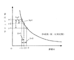
- the sound pressure of sound waves (the amplitude of sound waves) is inversely proportional to the distance from the sound source.
- the sound pressure attenuates rapidly at a position close to the sound source, and gradually decreases as the distance from the sound source increases.
- the microphone unit 1 when the microphone unit 1 is applied to a close-talking voice input device, the user's voice is generated in the vicinity of the microphone unit 1. Therefore, the user's voice is greatly attenuated between the first sound hole 111 and the second sound hole 112, and the sound pressure incident on the upper surface 122 a of the vibration film 122 and the sound pressure incident on the lower surface 122 b of the vibration film 122. A big difference appears between and.
- noise components such as background noise exist at a position where the sound source is farther from the microphone unit 1 than the user's voice. Therefore, the sound pressure of noise is hardly attenuated between the first sound hole 111 and the second sound hole 112, and is incident on the lower surface 122b of the vibration film 122 and the sound pressure incident on the upper surface 122a of the vibration film 122. There is almost no difference between sound pressure.
- the vibrating membrane 122 of the microphone unit 1 vibrates due to a difference in sound pressure between sound waves that are simultaneously incident on the first sound hole 111 and the second sound hole 112.
- the difference in sound pressure of noise incident on the upper surface 122a and the lower surface 122b of the vibration film 122 from a distance is very small, it is canceled out by the vibration film 122.
- the difference in sound pressure between user sounds incident on the upper surface 122 a and the lower surface 122 b of the vibration film 122 from a close position is large, the user sound does not cancel the vibration film 122 and vibrates the vibration film 122.
- the microphone unit 1 it can be considered that the vibrating membrane 122 is vibrating only by the user's voice. Therefore, the electrical signal output from the ASIC 13 of the microphone unit 1 can be regarded as a signal indicating only the user voice from which noise (background noise or the like) has been removed. That is, according to the microphone unit 1 of the present embodiment, it is possible to acquire an electrical signal indicating only the user voice from which noise has been removed with a simple configuration.
- the microphone unit 1 when the microphone unit 1 is configured as in the present embodiment, the sound pressure applied to the diaphragm 122 is the difference between the sound pressures input from the two sound holes 111 and 112. For this reason, the sound pressure that vibrates the vibrating membrane 122 becomes small, and the SNR of the extracted electrical signal tends to deteriorate.
- the microphone unit 1 of the present embodiment is devised to improve the SNR. This will be described below.
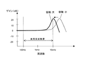
- FIG. 6 is a diagram for explaining a method for designing a diaphragm in a conventional microphone unit.
- the resonance frequency of the diaphragm provided in the microphone unit varies depending on the stiffness of the diaphragm, and the resonance frequency of the diaphragm is lowered when designed so as to reduce the stiffness.
- the stiffness is designed to be large, the resonance frequency of the diaphragm is increased.
- the diaphragm has been designed so that the resonance of the diaphragm does not affect the frequency band in which the microphone unit is used (the frequency band used).
- the stiffness of the diaphragm is set so that there is almost no gain change (flat band) with respect to the frequency change in the use frequency band of the microphone unit as shown in FIG. It was.
- the stiffness of the diaphragm is set large so that the resonance frequency of the diaphragm is about 20 kHz.
- the microphone unit 1 configured to vibrate the vibrating membrane 122 by the sound pressure difference between the upper surface 122a and the lower surface 122b of the vibrating membrane 122 as in the present embodiment has a problem that the SNR tends to deteriorate.
- the differential pressure in the vibration membrane 122 becomes small (see ⁇ p 1 and ⁇ p 2 in FIG. 5), so that the SNR of the microphone is improved.
- the interval between the two sound holes 111 and 112 needs to be increased to some extent.
- the present inventors desirably set the center-to-center distance between the first sound hole 111 and the second sound hole 112 to 4 mm or more and 6 mm or less, and more preferably to about 5 mm. The conclusion is more desirable. With such a configuration, a microphone unit that can ensure a high SNR (for example, 50 dB or more) can be obtained.
- a cross-sectional area of the sound path it is necessary to secure a cross-sectional area of the sound path to be equal to or larger than a certain value (for example, an area equivalent to a circle of about ⁇ 0.5 mm) in order to suppress deterioration of acoustic characteristics.
- a certain value for example, an area equivalent to a circle of about ⁇ 0.5 mm
- the volume of the first sound introduction space 113 and the second sound introduction space 114 is set. Will be big.
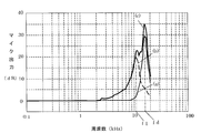
- FIG. 7 is a diagram for explaining the frequency characteristics of the sound guide space.
- the resonance frequency of the sound guide space decreases as the volume increases, and increases as the volume decreases.
- the microphone unit of the present embodiment tends to increase the volume of the sound guide spaces 113 and 114, and the resonance frequency of the sound guide spaces 113 and 114 tends to be lower than that of the conventional microphone unit.
- the resonance frequency of the sound guide spaces 113 and 114 appears at about 10 kHz.
- the frequency characteristics of the first sound introduction space 113 and the second sound introduction space 114 are designed to be substantially the same (that is, the resonance frequencies of both are also substantially the same).
- the frequency characteristics of the first sound introduction space 113 and the second sound introduction space 114 do not necessarily have to be substantially the same. However, if the frequency characteristics of both are substantially the same as in the present embodiment, for example, an acoustic resistance member or the like It is easy to obtain a microphone unit having a high SNR without using the.
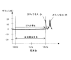
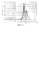
- FIG. 8 is a diagram for explaining the frequency characteristics of the microphone unit.
- 8A is a graph showing the frequency characteristics of the diaphragm
- FIG. 8B is the frequency characteristics of the sound guide space
- FIG. 8C is a graph showing the frequency characteristics of the microphone unit.
- the frequency characteristic of the microphone unit shows a frequency characteristic equivalent to a frequency characteristic obtained by combining the frequency characteristic of the diaphragm and the frequency characteristic of the sound guide space.
- the volume of the sound guide spaces 113 and 114 must be increased to some extent as described above. For this reason, it is difficult to set the resonance frequency of the sound guide spaces 113 and 114 to be high so that the resonance of the sound guide spaces 113 and 114 does not affect the above-described use frequency band. Considering this point, it is less meaningful to set the resonance frequency of the vibration film 122 to a high frequency (for example, 20 kHz) so that the resonance of the vibration film does not affect the above-described use frequency band. Rather, it is advantageous to improve the SNR of the microphone unit 1 by improving the sensitivity of the diaphragm 122 by bringing the resonance frequency of the diaphragm 122 close to the resonance frequency of the sound guide spaces 113 and 114.
- the resonance frequency fd of the diaphragm 122 is set within a range of ⁇ 4 kHz from the resonance frequency f1 of the first sound guide space 113 or the resonance frequency f2 of the second sound guide space 114.
- the SNR was good.
- the microphone unit 1 is configured such that the resonance frequency f1 of the first sound guide space 113 and the resonance frequency f2 of the second sound guide space 114 are substantially the same. For this reason, in the following description, the resonance frequency f1 of the first sound guide space 113 will be representatively described unless particularly necessary.
- FIG. 9 is a diagram illustrating frequency characteristics when the resonance frequency fd of the vibration film 122 is set to be approximately 4 kHz higher than the resonance frequency f1 of the first sound guide space 113 in the microphone unit 1 of the present embodiment.
- FIG. 10 is a diagram showing frequency characteristics when the resonance frequency fd of the vibrating membrane 122 is set to be approximately the same as the resonance frequency f1 of the first sound guide space 113 in the microphone unit 1 of the present embodiment.
- FIG. 11 is a diagram illustrating frequency characteristics when the resonance frequency fd of the vibrating membrane 122 is set to be approximately 4 kHz lower than the resonance frequency f1 of the first sound guide space 113 in the microphone unit 1 of the present embodiment. 9 to 11, (a) shows the frequency characteristic of the diaphragm 122, (b) shows the frequency characteristic of the first sound guide space 113, and (c) shows the frequency characteristic of the microphone unit 1.
- the resonance frequency f1 of the first sound guide space 113 is desirably as high as possible in order to increase the SNR of the microphone unit 1.
- the resonance frequency of the sound guide spaces 113 and 114 of the microphone unit 1 is set to be close to 11 kHz (10 Hz to 12 Hz).
- the peak derived from the resonance frequency fd of the diaphragm 122 is sharp, and the peak derived from the resonance frequency f1 of the first sound guide space 113 is broad. For this reason, even if the resonance frequency fd of the vibrating membrane 122 is brought close to a frequency approximately 4 kHz higher than the resonance frequency f1 of the first sound guide space 113, the frequency characteristics of the microphone unit 1 on the low frequency side are hardly affected.
- the frequency characteristic of the microphone unit 1 hardly fluctuates in the vicinity of 10 kHz, although the sensitivity is improved by lowering the resonance frequency fd of the diaphragm 122. That is, for example, when the upper limit on the high frequency side of the use frequency band in the microphone unit 1 is 10 kHz, the sensitivity of the diaphragm 122 is improved compared to the conventional one while maintaining the characteristics of the microphone unit 1 in the use frequency band. it can.
- the resonance frequency fd of the diaphragm 122 has never been low. However, if the resonance frequency fd of the diaphragm 122 is lowered too much, the above-described flat band (see, for example, FIG. 6) becomes narrow, and the SNR may be lowered. That is, there is a lower limit even if the resonance frequency fd of the vibration film 122 is lowered.
- the frequency characteristic of the microphone unit 1 is the resonance of the vibration film 122 from around 7 kHz.
- the effect of lowering the frequency fd begins to appear.
- the upper limit of the use frequency band of the microphone unit 1 is 10 kHz, there is some influence in the vicinity of 10 kHz, but such a design is possible in balance with the effect of improving the SNR by increasing the sensitivity of the diaphragm 122. is there.
- the upper limit of the voice band of the current mobile phone is 3.4 kHz.
- the resonance frequency fd of the vibration film 122 and the resonance frequency f1 of the first sound guide space 113 are substantially the same, the characteristics of the microphone unit 1 in the use frequency band are maintained and the vibration film 122 is compared with the conventional one. It can be said that the sensitivity of can be improved.
- FIG. 11 shows the result of further examination on how far the resonance frequency fd of the diaphragm 122 is lowered in consideration of the voice band of the current mobile phone.
- the frequency characteristic of 3.4 kHz that is the upper limit of the used voice band is required to be within ⁇ 3 dB with respect to the output of 1 kHz.
- the resonance frequency fd of the vibration film 122 is lowered to about 4 kHz from the resonance frequency f1 of the first sound guide space 113.
- the resonance frequency fd of the diaphragm 122 can be lowered to about 7 kHz, and an improvement in SNR due to an improvement in sensitivity of the diaphragm 122 can be expected.
- the resonance frequency fd of the vibration film 122 is ⁇ 4 kHz from the resonance frequency f1 of the first sound guide space 113 (or the resonance frequency f2 of the second sound guide space 114). If it is within the range, it can be said that an improvement in SNR can be expected when the microphone unit 1 is applied to an audio input device.
- the vibrating membrane 122 of the microphone unit 1 of the present embodiment can be formed of silicon, for example.
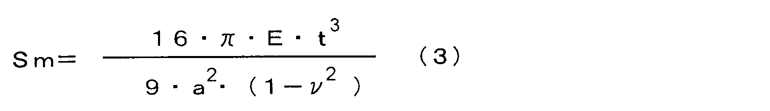
- the material for forming the vibration film 122 is not limited to silicon. A desirable design condition when the vibration film 122 is formed of silicon will be described. Note that the diaphragm 122 is modeled as shown in FIG.
- the resonance frequency fd (Hz) of the vibrating membrane 122 is expressed by the following formula (1) when the stiffness of the vibrating membrane 122 is Sm (N / m) and the mass of the vibrating membrane 122 is Mm (kg). .
- the stiffness Sm of the vibration film 122 and the mass Mm of the vibration film 122 are expressed by the following equations (2) and (3), respectively (see Non-Patent Document 1).
- E Young's modulus (Pa) of the vibrating membrane 122
- ⁇ density (kg / m 3 ) of the vibrating membrane 122
- ⁇ Poisson's ratio of the vibrating membrane 122
- a radius (m) of the vibrating membrane
- t This is the thickness (m) of the vibrating membrane 122.
- the resonance frequency fd of the vibration film 122 is expressed as the following equation (4).
- the resonance frequency fd of the vibrating membrane 122 is preferably ⁇ 4 kHz from the resonance frequency f1 of the first sound guide space 113. If the desired resonance frequency f1 of the first sound guide space 113 is 11 kHz, it is desirable that the resonance frequency fd of the diaphragm 122 satisfies the following formula (5).
- a high SNR can be obtained by setting the radius a and the thickness t of the diaphragm 122 so as to satisfy Equation (6).
- a high-performance microphone unit 1 that can be secured can be obtained.
- the embodiment described above is an example, and the microphone unit of the present invention is not limited to the configuration of the embodiment described above. Various modifications may be made to the configuration of the embodiment described above without departing from the object of the present invention.
- the diaphragm 122 (diaphragm) is arranged in parallel to the surface 11a of the housing 11 where the sound holes 111 and 112 are formed.
- the present invention is not limited to this configuration, and the diaphragm may not be parallel to the surface on which the sound hole of the housing is formed.
- a so-called condenser microphone is adopted as a configuration of a microphone having a diaphragm (corresponding to the MEMS chip 12).
- the present invention can also be applied to a microphone unit that employs a configuration other than a condenser microphone as a configuration of a microphone having a diaphragm.
- Examples of configurations other than the condenser microphone having the diaphragm include electrodynamic (dynamic), electromagnetic (magnetic), and piezoelectric microphones.
- the microphone unit of the present invention is suitable for an information processing system, a sound recording device, and the like using a technology for analyzing an input sound such as a voice communication device such as a mobile phone or a transceiver, a voice authentication system, and the like.
Abstract
Description


11 筐体
12 MEMSチップ
13 ASIC(電気回路部)
111 第1音孔
112 第2音孔
113 第1導音空間
114 第2導音空間
122 振動膜(振動板)
122a 振動膜の上面(振動板の第1の面)
122b 振動膜の下面(振動板の第2の面)
Claims (5)
- 筐体と、
前記筐体の内部に配置される振動板と、
前記振動板の振動に基づいて発生する電気信号を処理する電気回路部と、を備えるマイクロホンユニットであって、
前記筐体には、第1音孔を介して前記筐体外部の音を前記振動板の第1の面へと導く第1導音空間と、第2音孔を介して前記筐体外部の音を前記振動板の前記第1の面の裏面である第2の面へと導く第2導音空間と、が設けられ、
前記振動板の共振周波数が、前記第1導音空間及び前記第2導音空間のうち少なくとも一方の共振周波数を基準に±4kHzの範囲内に設定されているマイクロホンユニット。 - 請求項1に記載のマイクロホンユニットであって、
前記第1音孔と前記第2音孔とは同一面内に形成され、前記第1音孔と前記第2音孔との中心間距離が4mm以上6mm以下である。 - 請求項1又は2に記載のマイクロホンユニットであって、
前記第1導音空間と前記第2導音空間との共振周波数は略同一である。 - 請求項1又は2に記載のマイクロホンユニットであって、
前記第1導音空間及び前記第2導音空間のうち少なくと一方の共振周波数は、10kHz以上12kHz以下である。 - 請求項1又は2に記載のマイクロホンユニットであって、
前記振動板の共振周波数が、前記第1導音空間及び前記第2導音空間のうち少なくとも一方の共振周波数と略同一に設定されている。
Priority Applications (3)
| Application Number | Priority Date | Filing Date | Title |
|---|---|---|---|
| EP09830470.2A EP2355541B1 (en) | 2008-12-05 | 2009-12-04 | Microphone unit |
| CN200980149153.XA CN102239704B (zh) | 2008-12-05 | 2009-12-04 | 麦克风单元 |
| US13/131,447 US8948432B2 (en) | 2008-12-05 | 2009-12-04 | Microphone unit |
Applications Claiming Priority (2)
| Application Number | Priority Date | Filing Date | Title |
|---|---|---|---|
| JP2008310506A JP5325555B2 (ja) | 2008-12-05 | 2008-12-05 | マイクロホンユニット |
| JP2008-310506 | 2008-12-05 |
Publications (1)
| Publication Number | Publication Date |
|---|---|
| WO2010064704A1 true WO2010064704A1 (ja) | 2010-06-10 |
Family
ID=42233351
Family Applications (1)
| Application Number | Title | Priority Date | Filing Date |
|---|---|---|---|
| PCT/JP2009/070388 WO2010064704A1 (ja) | 2008-12-05 | 2009-12-04 | マイクロホンユニット |
Country Status (7)
| Country | Link |
|---|---|
| US (1) | US8948432B2 (ja) |
| EP (1) | EP2355541B1 (ja) |
| JP (1) | JP5325555B2 (ja) |
| KR (1) | KR20110091868A (ja) |
| CN (1) | CN102239704B (ja) |
| TW (1) | TWI508574B (ja) |
| WO (1) | WO2010064704A1 (ja) |
Families Citing this family (19)
| Publication number | Priority date | Publication date | Assignee | Title |
|---|---|---|---|---|
| CN201274566Y (zh) * | 2008-09-26 | 2009-07-15 | 瑞声声学科技(深圳)有限公司 | Mems麦克风 |
| TWM390627U (en) * | 2010-05-31 | 2010-10-11 | Lingsen Precision Ind Ltd | MEMS microphone carrier module |
| US9247338B2 (en) | 2010-12-28 | 2016-01-26 | Nec Corporation | Electroacoustic transducer |
| TWI508573B (zh) * | 2011-07-08 | 2015-11-11 | Aver Information Inc | 麥克風單元 |
| TWI450599B (zh) * | 2012-02-22 | 2014-08-21 | Merry Electronics Co Ltd | 薄形化微機電麥克風模組 |
| CN104956693B (zh) * | 2012-10-18 | 2018-08-03 | 诺基亚技术有限公司 | 用于音频换能器系统的谐振阻尼 |
| KR101369464B1 (ko) * | 2013-06-27 | 2014-03-06 | 주식회사 비에스이 | 멤스 마이크로폰 |
| CN104036783B (zh) * | 2014-05-19 | 2017-07-18 | 孙国华 | 磁共振成像扫描设备自适应语音增强系统 |
| CN104507029A (zh) * | 2015-01-09 | 2015-04-08 | 歌尔声学股份有限公司 | 一种指向性mems麦克风 |
| KR101692255B1 (ko) | 2015-10-06 | 2017-01-04 | 서강대학교산학협력단 | 간섭계를 이용한 마이크로폰 |
| DE102016220500A1 (de) * | 2016-10-19 | 2018-04-19 | Robert Bosch Gmbh | Vorrichtung und Verfahren zur Überprüfung eines Rads eines Schienenfahrzeugs auf Flachstellen |
| US10887686B2 (en) | 2018-08-28 | 2021-01-05 | Ampacs Corporation | Directional microphone |
| CN109040927B (zh) * | 2018-10-26 | 2024-02-06 | 歌尔科技有限公司 | 一种指向性麦克风及声音采集设备 |
| CN109889967B (zh) * | 2019-03-28 | 2020-10-30 | 百度在线网络技术(北京)有限公司 | 麦克风和智能语音设备 |
| JP7211220B2 (ja) | 2019-04-05 | 2023-01-24 | 株式会社デンソー | 超音波センサ |
| JP7226154B2 (ja) | 2019-07-10 | 2023-02-21 | 株式会社デンソー | 超音波センサ |
| WO2023015486A1 (zh) * | 2021-08-11 | 2023-02-16 | 深圳市韶音科技有限公司 | 一种传声器 |
| WO2023092420A1 (zh) * | 2021-11-25 | 2023-06-01 | 深圳市韶音科技有限公司 | 传声器 |
| CN114374920A (zh) * | 2021-12-29 | 2022-04-19 | 瑞声声学科技(深圳)有限公司 | 骨传导麦克风 |
Citations (5)
| Publication number | Priority date | Publication date | Assignee | Title |
|---|---|---|---|---|
| JPH04217199A (ja) | 1990-02-28 | 1992-08-07 | American Teleph & Telegr Co <Att> | 指向性マイクロホンアセンブリ |
| JPH08340592A (ja) * | 1995-05-11 | 1996-12-24 | At & T Corp | ノイズを除去する勾配型マイクロホンアセンブリ |
| JP2004282449A (ja) * | 2003-03-17 | 2004-10-07 | Sanken Microphone Kk | コンデンサ型広帯域マイクロホン |
| JP2007098486A (ja) | 2005-09-30 | 2007-04-19 | Aisin Aw Co Ltd | ボルト供給装置 |
| JP2008258904A (ja) * | 2007-04-04 | 2008-10-23 | Funai Electric Advanced Applied Technology Research Institute Inc | マイクロフォンユニット、及び、接話型の音声入力装置、並びに、情報処理システム |
Family Cites Families (10)
| Publication number | Priority date | Publication date | Assignee | Title |
|---|---|---|---|---|
| US4843628A (en) * | 1986-07-10 | 1989-06-27 | Stanton Magnetics, Inc. | Inertial microphone/receiver with extended frequency response |
| US5272758A (en) * | 1991-09-09 | 1993-12-21 | Hosiden Corporation | Electret condenser microphone unit |
| US6122389A (en) * | 1998-01-20 | 2000-09-19 | Shure Incorporated | Flush mounted directional microphone |
| AU2003236375A1 (en) * | 2002-04-05 | 2003-10-20 | Matsushita Electric Industrial Co., Ltd. | Capacitor sensor |
| JP2005244427A (ja) * | 2004-02-25 | 2005-09-08 | Audio Technica Corp | 単一指向性コンデンサマイクロホンユニット |
| JP2005295278A (ja) * | 2004-03-31 | 2005-10-20 | Hosiden Corp | マイクロホン装置 |
| US7756285B2 (en) * | 2006-01-30 | 2010-07-13 | Songbird Hearing, Inc. | Hearing aid with tuned microphone cavity |
| KR20080005854A (ko) * | 2006-07-10 | 2008-01-15 | 야마하 가부시키가이샤 | 압력 센서 및 그의 제조 방법 |
| US8180082B2 (en) * | 2007-04-04 | 2012-05-15 | Funai Electric Advanced Applied Technology Research Institute Inc. | Microphone unit, close-talking voice input device, information processing system, and method of manufacturing microphone unit |
| JP2008278476A (ja) * | 2007-04-05 | 2008-11-13 | Yamaha Corp | コンデンサマイク装置のsn比改善方法およびコンデンサマイク装置並びにコンデンサマイク装置搭載機器 |
-
2008
- 2008-12-05 JP JP2008310506A patent/JP5325555B2/ja not_active Expired - Fee Related
-
2009
- 2009-12-02 TW TW098141187A patent/TWI508574B/zh not_active IP Right Cessation
- 2009-12-04 EP EP09830470.2A patent/EP2355541B1/en not_active Not-in-force
- 2009-12-04 WO PCT/JP2009/070388 patent/WO2010064704A1/ja active Application Filing
- 2009-12-04 CN CN200980149153.XA patent/CN102239704B/zh not_active Expired - Fee Related
- 2009-12-04 US US13/131,447 patent/US8948432B2/en not_active Expired - Fee Related
- 2009-12-04 KR KR20117013332A patent/KR20110091868A/ko not_active Application Discontinuation
Patent Citations (5)
| Publication number | Priority date | Publication date | Assignee | Title |
|---|---|---|---|---|
| JPH04217199A (ja) | 1990-02-28 | 1992-08-07 | American Teleph & Telegr Co <Att> | 指向性マイクロホンアセンブリ |
| JPH08340592A (ja) * | 1995-05-11 | 1996-12-24 | At & T Corp | ノイズを除去する勾配型マイクロホンアセンブリ |
| JP2004282449A (ja) * | 2003-03-17 | 2004-10-07 | Sanken Microphone Kk | コンデンサ型広帯域マイクロホン |
| JP2007098486A (ja) | 2005-09-30 | 2007-04-19 | Aisin Aw Co Ltd | ボルト供給装置 |
| JP2008258904A (ja) * | 2007-04-04 | 2008-10-23 | Funai Electric Advanced Applied Technology Research Institute Inc | マイクロフォンユニット、及び、接話型の音声入力装置、並びに、情報処理システム |
Non-Patent Citations (2)
| Title |
|---|
| JEN-YI CHEN, YU-CHUN HSUL, TAMAL MUKHERJEE, GRAY K. FEDDER: "MODELING AND SIMULATION OF A CONDENSER MICROPHONE", PROC. TRANSDUCER'07, LYON, FRANCE, vol. 1, 2007, pages 1299 - 1302 |
| See also references of EP2355541A4 * |
Also Published As
| Publication number | Publication date |
|---|---|
| US20110235841A1 (en) | 2011-09-29 |
| EP2355541B1 (en) | 2013-10-30 |
| EP2355541A4 (en) | 2012-06-06 |
| US8948432B2 (en) | 2015-02-03 |
| JP5325555B2 (ja) | 2013-10-23 |
| KR20110091868A (ko) | 2011-08-16 |
| JP2010136133A (ja) | 2010-06-17 |
| EP2355541A1 (en) | 2011-08-10 |
| TW201028019A (en) | 2010-07-16 |
| CN102239704B (zh) | 2014-05-28 |
| CN102239704A (zh) | 2011-11-09 |
| TWI508574B (zh) | 2015-11-11 |
Similar Documents
| Publication | Publication Date | Title |
|---|---|---|
| JP5325555B2 (ja) | マイクロホンユニット | |
| JP5502313B2 (ja) | マイクロホンユニット | |
| JP5325554B2 (ja) | 音声入力装置 | |
| JP5636796B2 (ja) | マイクロホンユニット | |
| JP5834383B2 (ja) | マイクロホンユニット及びそれを備えた音声入力装置 | |
| JP5481852B2 (ja) | マイクロホンユニット及びそれを備えた音声入力装置 | |
| JP4293378B2 (ja) | マイクロフォンユニット、及び、接話型の音声入力装置、並びに、情報処理システム | |
| JP2010187076A (ja) | マイクロホンユニット | |
| JP2010183312A (ja) | マイクロホンユニット | |
| JP5636795B2 (ja) | マイクロホンユニット | |
| WO2022100551A1 (zh) | Mems压电微扬声器、微扬声器单元及电子设备 | |
| KR20090053721A (ko) | 마이크로폰 시스템, 소리 입력 장치 및 그 제조 방법 | |
| US9420365B2 (en) | Silicon condenser microphone | |
| JP5419254B2 (ja) | マイクロホンユニット | |
| JP5257920B2 (ja) | 携帯電話およびマイクロホンユニット | |
| JP5166007B2 (ja) | マイクロフォンユニットおよびその製造方法 | |
| JP5008638B2 (ja) | マイクロフォンユニット、音声入力装置、情報処理システム及びマイクロフォンユニットの製造方法 | |
| CN113259819A (zh) | 麦克风 |
Legal Events
| Date | Code | Title | Description |
|---|---|---|---|
| WWE | Wipo information: entry into national phase |
Ref document number: 200980149153.X Country of ref document: CN |
|
| 121 | Ep: the epo has been informed by wipo that ep was designated in this application |
Ref document number: 09830470 Country of ref document: EP Kind code of ref document: A1 |
|
| WWE | Wipo information: entry into national phase |
Ref document number: 13131447 Country of ref document: US |
|
| WWE | Wipo information: entry into national phase |
Ref document number: 2009830470 Country of ref document: EP |
|
| NENP | Non-entry into the national phase |
Ref country code: DE |
|
| ENP | Entry into the national phase |
Ref document number: 20117013332 Country of ref document: KR Kind code of ref document: A |