WO2010050372A1 - 帯電部材およびその製造方法、プロセスカートリッジ及び電子写真装置 - Google Patents
帯電部材およびその製造方法、プロセスカートリッジ及び電子写真装置 Download PDFInfo
- Publication number
- WO2010050372A1 WO2010050372A1 PCT/JP2009/067969 JP2009067969W WO2010050372A1 WO 2010050372 A1 WO2010050372 A1 WO 2010050372A1 JP 2009067969 W JP2009067969 W JP 2009067969W WO 2010050372 A1 WO2010050372 A1 WO 2010050372A1
- Authority
- WO
- WIPO (PCT)
- Prior art keywords
- graphite particles
- surface layer
- graphite
- particles
- charging member
- Prior art date
- Legal status (The legal status is an assumption and is not a legal conclusion. Google has not performed a legal analysis and makes no representation as to the accuracy of the status listed.)
- Ceased
Links
Images

Classifications
-
- G—PHYSICS
- G03—PHOTOGRAPHY; CINEMATOGRAPHY; ANALOGOUS TECHNIQUES USING WAVES OTHER THAN OPTICAL WAVES; ELECTROGRAPHY; HOLOGRAPHY
- G03G—ELECTROGRAPHY; ELECTROPHOTOGRAPHY; MAGNETOGRAPHY
- G03G21/00—Arrangements not provided for by groups G03G13/00 - G03G19/00, e.g. cleaning, elimination of residual charge
- G03G21/16—Mechanical means for facilitating the maintenance of the apparatus, e.g. modular arrangements
- G03G21/18—Mechanical means for facilitating the maintenance of the apparatus, e.g. modular arrangements using a processing cartridge, whereby the process cartridge comprises at least two image processing means in a single unit
-
- G—PHYSICS
- G03—PHOTOGRAPHY; CINEMATOGRAPHY; ANALOGOUS TECHNIQUES USING WAVES OTHER THAN OPTICAL WAVES; ELECTROGRAPHY; HOLOGRAPHY
- G03G—ELECTROGRAPHY; ELECTROPHOTOGRAPHY; MAGNETOGRAPHY
- G03G15/00—Apparatus for electrographic processes using a charge pattern
- G03G15/02—Apparatus for electrographic processes using a charge pattern for laying down a uniform charge, e.g. for sensitising; Corona discharge devices
- G03G15/0208—Apparatus for electrographic processes using a charge pattern for laying down a uniform charge, e.g. for sensitising; Corona discharge devices by contact, friction or induction, e.g. liquid charging apparatus
- G03G15/0216—Apparatus for electrographic processes using a charge pattern for laying down a uniform charge, e.g. for sensitising; Corona discharge devices by contact, friction or induction, e.g. liquid charging apparatus by bringing a charging member into contact with the member to be charged, e.g. roller, brush chargers
- G03G15/0233—Structure, details of the charging member, e.g. chemical composition, surface properties
-
- G—PHYSICS
- G03—PHOTOGRAPHY; CINEMATOGRAPHY; ANALOGOUS TECHNIQUES USING WAVES OTHER THAN OPTICAL WAVES; ELECTROGRAPHY; HOLOGRAPHY
- G03G—ELECTROGRAPHY; ELECTROPHOTOGRAPHY; MAGNETOGRAPHY
- G03G15/00—Apparatus for electrographic processes using a charge pattern
- G03G15/02—Apparatus for electrographic processes using a charge pattern for laying down a uniform charge, e.g. for sensitising; Corona discharge devices
-
- Y—GENERAL TAGGING OF NEW TECHNOLOGICAL DEVELOPMENTS; GENERAL TAGGING OF CROSS-SECTIONAL TECHNOLOGIES SPANNING OVER SEVERAL SECTIONS OF THE IPC; TECHNICAL SUBJECTS COVERED BY FORMER USPC CROSS-REFERENCE ART COLLECTIONS [XRACs] AND DIGESTS
- Y10—TECHNICAL SUBJECTS COVERED BY FORMER USPC
- Y10T—TECHNICAL SUBJECTS COVERED BY FORMER US CLASSIFICATION
- Y10T428/00—Stock material or miscellaneous articles
- Y10T428/25—Web or sheet containing structurally defined element or component and including a second component containing structurally defined particles
Definitions
- the present invention relates to a charging member, a manufacturing method thereof, a process cartridge, and an electrophotographic apparatus.
- Japanese Patent Application Laid-Open No. 2004-157384 discloses a conductive elastic layer made of rubber having units derived from ethylene oxide such as epichlorohydrin rubber, and a charge having a conductive coating layer as a surface layer on the conductive elastic layer. A member is disclosed.
- the rubber constituting the conductive elastic layer has a high hygroscopicity because it has units derived from ethylene oxide. Therefore, the conductive elastic layer repeats expansion and contraction due to ambient humidity. As the conductive elastic layer expands and contracts, the conductive coating layer on the conductive elastic layer also expands and contracts.
- the present inventors have found that the following problems may occur when the conductive coating layer is made conductive by dispersing conductive particles in a binder resin. That is, it has been found that the conductive particles in the conductive coating layer move and the conductive particles aggregate due to repeated expansion and contraction of the conductive coating layer. Such agglomeration of conductive particles leads to non-uniform volume resistance of the conductive coating layer.
- the present inventors have recognized that this is a problem to be solved in order to obtain a charging member with more stable performance. Therefore, the present invention provides a charging member in which aggregation of conductive particles in the surface layer is suppressed even when the conductive surface layer repeatedly expands and contracts under various environments, and the charging performance hardly changes. It is directed to providing a manufacturing method. The present invention is also directed to providing an electrophotographic apparatus and a process cartridge that can stably form high-quality electrophotographic images even in various environments. The present inventors have made various studies on the above-described problems.
- the charging member according to the present invention is a charging member having a conductive base, and a conductive elastic layer and a conductive surface layer formed on the base, and the elastic layer is derived from ethylene oxide.
- a polymer having a unit, the surface layer includes a binder resin and graphite particles, and the binder resin includes a urethane bond, a siloxane bond, or a resin having a urethane bond and a siloxane bond in a molecule.
- the graphite particles are characterized in that the interplanar spacing of the graphite (002) plane is 0.3362 nm or more and 0.3449 nm or less.
- the process cartridge according to the present invention is characterized in that the charging member and the member to be charged are integrated and configured to be detachable from the main body of the electrophotographic apparatus.
- an electrophotographic apparatus according to the present invention includes the above-described charging member and a member to be charged that is charged by the charging member.
- the spacing between the raw material of the resin having a urethane bond, a siloxane bond or a urethane bond and a siloxane bond in the molecule and the graphite (002) plane is 0.3362 nm.
- the method includes a step of applying a coating solution for forming a surface layer containing graphite particles of 0.3449 nm or less onto the elastic layer, and reacting the raw material of the resin to form the surface layer.
- FIG. 1 is a sectional view of a charging roller according to the present invention.
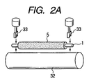
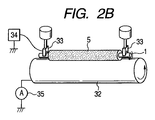
- 2A and 2B are explanatory diagrams of a method for measuring the electrical resistance value of the charging roller according to the present invention.
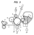
- FIG. 3 is a sectional view of the electrophotographic apparatus according to the present invention.
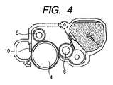
- FIG. 4 is a cross-sectional view of a process cartridge according to the present invention.
- FIG. 1 is a cross-sectional view of a roller-shaped charging member (hereinafter also referred to as “charging roller”) according to the present invention.
- a conductive elastic layer 2 and a conductive surface layer 3 are laminated in this order on a conductive substrate 1.
- the surface layer 3 includes a binder resin and graphite particles dispersed in the binder resin.
- the graphite particles have a graphite (002) plane spacing of 0.3362 nm or more and 0.3449 nm or less.
- the binder resin contains a resin having a urethane bond, a siloxane bond, or a urethane bond and a siloxane bond in the molecule.
- the present inventors include a conductive elastic layer made of rubber having a unit derived from ethylene oxide, a urethane resin covering the conductive elastic layer, and graphite particles dispersed in the urethane resin.
- the following experiment was conducted on a charging roller composed of a conductive surface layer. That is, as the conductive particles in the surface layer, a plurality of charging rollers having a common configuration were prepared except that graphite particles having different plane spacing of the graphite (002) plane were used. These charging rollers were subjected to an environmental test.
- these charging rollers are placed in an environment of temperature 23 ° C. and humidity 55% RH (hereinafter also referred to as “N / N environment”) for 24 hours, and then placed in an environment of temperature 40 ° C. and humidity 95% RH 30. Set aside for 7 days in an N / N environment. Then, the state of the graphite particles in the surface layer of each charging roller subjected to the environmental test was observed with an electron microscope, and the change in the dispersion state of the graphite particles in the surface layer before and after the environmental test was observed.
- the surface layer using graphite particles having a graphite (002) plane spacing in the range of 0.3362 to 0.3449 nm exhibits a very large change in the dispersion state of the graphite particles in the surface layer before and after the environmental test. There were few. Similar results were obtained with a plurality of charging rollers prepared in the same manner except that the urethane resin was changed to dimethylpolysiloxane in the above experiment. From these experimental results, in the surface layer containing the graphite particles having a graphite (002) plane spacing of 0.3362 to 0.3449 nm, the graphite particles are relatively relative to the binder resin present in the surroundings. It is considered that the position is almost fixed (immobilize).
- the value of the interplanar spacing of the graphite (002) plane is a parameter indicating the degree of development of crystallization of graphite particles. Accordingly, the numerical range of the interplanar spacing according to the present invention is such that the regularity is not as complete as that of general graphite, although aromatic network planes are fairly highly regularly stacked. It defines graphite particles having a layered structure. By the way, carbon having an incompletely stacked structure is represented by 2 from the right in FIG. 1.4 on page 56 of the document “Carbon Black Handbook 3rd Edition” (issued by the Carbon Black Association on April 15, 1995).
- the binder resin is intercalated between the layers of the graphite particles due to the affinity between the polar group present in the spread portion and the defect portion and the urethane bond or siloxane bond of the binder resin. Conceivable.
- graphite having an interplanar spacing of 0.3354 nm has an interlayer distance that is too small, and in the process of graphitizing the carbon precursor, the polar groups that existed between the layers are almost decomposed. The possibility of intercalating is very low. This is because “graphite is a substance having a layered structure with a strong anisotropy with a distance between layer planes of 0.335 nm” in JP-A-2004-217450 [0003] It is supported by the statement that “the reaction to attack does not proceed easily”. On the other hand, the conductivity of the graphite particles decreases as the interplanar spacing increases from 0.3354 nm, which is the interplanar spacing of perfect graphite.
- the crystal structure in which the hexagonal mesh planes of graphite particles are stacked is known to have high conductivity because ⁇ electrons that move like free electrons exist in the hexagonal mesh plane (“Hitachi”). (Refer to the 2nd to 6th lines in the right column of the second page of the powder metallurgy technical report No. 3 (2004)). Therefore, as the interlayer distance increases, the mobility of the ⁇ electrons is hindered, and the conductivity decreases.
- the numerical range of the interplanar spacing of the graphite (002) plane of the graphite particles according to the present invention has good conductivity and is suitable for intercalating a binder resin between layers. Has a technical meaning.
- the average particle diameter of the graphite particles is preferably 0.5 to 15 ⁇ m, and particularly preferably 1 to 8 ⁇ m.
- the current flow in the charging member can be controlled, and the effect of suppressing the resistance fluctuation can be exhibited. .
- the ratio of the major axis / minor axis of the graphite particles is more preferably 2 or less. By setting it within this range, it becomes possible to more easily control the flow of current in the charging member. At the same time, it is possible to more reliably suppress the occurrence of blotches in the electrophotographic image due to excessive discharge or insufficient discharge.
- the graphite particles having a particle diameter in the range of 0.5 A or more and 5 A or less is more preferably 80% or more of the total graphite particles.
- the occupation amount of the graphite particles in the surface layer is 1% to 50%, preferably 2% to 30% in terms of volume occupation ratio.
- the graphite particles are preferably mixed in an amount of 0.5 to 50 parts by mass with respect to 100 parts by mass of the binder resin. More preferably, it is 1 part by mass or more, and particularly preferably 2 parts by mass to 30 parts by mass. By setting it as this range, the said volume occupation rate can be controlled to a more preferable range. Therefore, the effect of suppressing the expansion of the surface layer due to heat or moisture can be more remarkably exhibited. Further, the flow of current in the charging member can be more easily controlled, and at the same time, the occurrence of the blotch can be more reliably suppressed.
- the graphite particles are a substance containing carbon atoms having a layer structure by SP2 covalent bond.
- the graphite particles are derived from graphite in a Raman spectrum, 1580 cm. -1
- the peak half-width of the peak of 80cm is 80cm -1
- the following is preferable, 60 cm -1
- Artificial graphite is suitably used as the graphite particles.
- graphite particles obtained by graphitizing a carbon precursor obtained from coke, tar pitch, bulk mesophase pitch, mesocarbon microbeads, and the like having many functional groups bonded thereto can be used. The outline of the method for producing graphite particles according to the present invention is described below.
- -Particles obtained by graphite treatment of coke etc . can be obtained by adding a binder such as pitch to a filler such as coke and then firing.
- a binder such as pitch
- the filler residual oil in petroleum distillation, or coke obtained by baking raw coke obtained by heating coal tar pitch at about 500 ° C. at 1200 ° C. to 1400 ° C.
- the binder a pitch obtained as a distillation residue of tar can be used.
- the coke particles are finely pulverized so as to have a volume average particle diameter of about 10 ⁇ m, and mixed with a resin containing oxygen atoms in the molecule (for example, furan resin).
- the graphite particles according to the present invention can be obtained by heat treatment at a temperature of 2600 to 3000 ° C. for about 10 to 20 minutes.
- ⁇ Particles obtained by graphite treatment of bulk mesophase pitch can be obtained, for example, by extracting ⁇ -resin from a coal tar pitch or the like by solvent fractionation, and performing hydrogenation and heavy treatment. Further, after the heavy treatment, the solvent-soluble component can be removed by pulverization and then benzene or toluene.
- This bulk mesophase pitch preferably has a quinoline soluble content of 95% by mass or more. When the amount less than 95% by mass is used, the inside of the particles is hardly liquid-phase carbonized, and the particles remain in a crushed state due to solid-phase carbonization.
- the above-mentioned bulk mesophase pitch is finely pulverized, heat-treated at 200 to 350 ° C. in air, and lightly oxidized.
- the bulk mesophase pitch particles are infusibilized only on the surface, and melting and fusion during the graphite treatment in the next step are prevented.
- the oxidized bulk mesophase pitch particles suitably have an oxygen content of 5% by mass to 15% by mass.
- desired graphite particles are obtained by heat-treating the oxidized bulk mesophase pitch particles at 1000 ° C.
- the reaction product is treated by filtration, stationary sedimentation, centrifugation, etc. to separate mesocarbon microbeads, and then washed with a solvent such as benzene, toluene, xylene, and the like, and further dried.
- a solvent such as benzene, toluene, xylene, and the like
- graphite particles using these mesocarbon microbeads
- the mesocarbon microbeads that have been dried are first mechanically dispersed with a force that does not destroy them. It is preferable for preventing or obtaining a uniform particle size.
- the mesocarbon microbeads that have finished the primary dispersion are primarily heated and carbonized at a temperature of 200 to 1500 ° C. in an inert atmosphere.
- the obtained carbide is mechanically dispersed with a force not to destroy the carbide in order to prevent coalescence of the particles after the graphite treatment and to obtain a uniform particle size.
- Desired graphite particles are obtained by heating the dispersed carbide at 1000 to 3500 ° C. for 10 to 60 minutes in an inert atmosphere. Even when mesocarbon microbeads are used as the carbon precursor, the interplanar spacing decreases as the heating temperature during the heat treatment increases, and the interplanar spacing decreases as the heat treatment time increases. Therefore, the temperature and time of the heat treatment are appropriately adjusted within the above range.
- the binder resin needs to have a urethane bond, a siloxane bond, or a urethane bond and a siloxane bond in the molecule.
- the urethane bond portion and the siloxane bond portion serve to play an important role in the intercalation of the binder resin between the layers of the graphite particles according to the present invention.
- Specific examples of the resin include a polyurethane resin and a silicone resin.
- a surface layer containing a polyurethane resin is formed by applying a coating liquid for forming a surface layer containing the above graphite particles and a compound having a polyol and an isocyanate group to a surface such as an elastic layer, and a compound having a polyol and an isocyanate group. It can be formed by reacting.
- the surface layer containing the silicone resin is prepared by applying a coating solution for forming a surface layer containing the above graphite particles and hydrolyzable organosiloxane to the surface of an elastic layer or the like, and dehydrating condensation or desorption of the organosiloxane. It can be formed by alcohol condensation.
- examples of the hydrolyzable organosiloxane include silane compounds having two or three hydrolyzable groups in the molecule, such as trialkoxysilane and dialkoxysilane.
- a silane compound having two or three hydrolyzable groups in the molecule is preferable because the binder resin can be made flexible.
- a resin grafted with a urethane bond or a siloxane bond is preferable. It is presumed that the intercalation of the binder resin to the graphite particles occurs in parallel with the formation of urethane bonds and siloxane bonds in the coating film of the coating solution applied to the surface of the elastic layer or the like.
- the binder resin can be efficiently intercalated with the graphite particles because the urethane bond or the siloxane bond is in the graft portion having a high degree of freedom of movement in the coating film.
- the hard segment (main chain) is an acrylic resin or styrene resin having a carbon-carbon bond
- the soft segment The structure which has a urethane bond and a siloxane bond in the side chain
- R1 to R4 each independently represent a hydrogen atom, an alkyl group having 1 to 3 carbon atoms, a halogen atom, or the like, and m and n represent an integer of 0 or more. , L represents an integer of 1 or more.
- the graft polymer having a urethane bond in the side chain can be synthesized by reacting a polyol having a main chain composed of an acrylic resin or a styrene resin and having a hydroxyl group in the side chain with a compound having an isocyanate group.
- the graft polymer has a main chain of an acrylic resin or a styrene resin, an alkylene group having 2 or more carbon atoms in a side chain, and a polyol and an isocyanate group in which a hydroxyl group is bonded to the alkylene group via an ester group or the like.
- the polyol used here can be synthesized by adding and polymerizing a hydroxyl group-containing acrylate such as hydroxyalkyl methacrylate or hydroxyalkyl acrylate to an acrylic monomer or a styrene monomer.
- a hydroxyl group-containing acrylate such as hydroxyalkyl methacrylate or hydroxyalkyl acrylate
- the epsilon-caprolactone modified polyol which introduce
- the ⁇ -caprolactone-modified polyol is listed as “Placcel DC2016” (trade name) by Daicel Chemical Industries, Ltd., for example.
- the following compound can be illustrated as a compound which has an isocyanate group.
- Aliphatic diisocyanates hexamethylene diisocyanate, trimethylhexamethylene diisocyanate, etc.
- alicyclic diisocyanates isophorone diisocyanate, etc.
- aromatic aliphatic diisocyanates xylylene diisocyanate, etc.
- aromatic diisocyanates tolylene diisocyanate, 4,4-diphenylmethane diisocyanate, etc.
- dimers and trimers of each of the above diisocyanates are dimers and trimers of each of the above diisocyanates.
- aliphatic diisocyanate is more preferable in order to obtain a urethane resin having a side chain with a greater degree of freedom of movement.
- a trimer in order to form a urethane bond three-dimensionally and enhance the effect of suppressing the change in the position of the graphite particles.
- a graft polymer having a siloxane bond in the side chain can be obtained by dehydration condensation or dealcoholization condensation of a polyol having a hydroxyl group in the side chain and a mixture of trialkoxysilane and dialkoxysilane.
- a siloxane bond-containing acrylate such as a silicone-modified methacrylate or a silicone-modified acrylate
- the urethane bond and the siloxane bond are more preferably contained in an amount of 2% by mass or more based on the total amount of the binder resin.
- a fluororesin, a polyamide resin, an acrylic resin, a butyral resin, and the like can be given.
- natural rubber, a vulcanized product thereof, rubber such as synthetic rubber or the like may be added.
- the surface layer it is more preferable that 80% or more of the total number of graphite particles exists at intervals of 10 ⁇ m or more and 100 ⁇ m or less. Thereby, the effect of suppressing the expansion of the surface layer due to heat or moisture can be more remarkably exhibited. Further, the flow of current in the charging member can be more easily controlled, and at the same time, the occurrence of the blotch can be more reliably suppressed.
- the surface layer is 1 ⁇ 10 in a 23 ° C., 50% RH environment.
- the volume resistivity of the surface layer is determined as follows. First, the surface layer is peeled off from the roller state and cut into a rectangle of about 5 mm ⁇ 5 mm. Metal is vapor-deposited on both surfaces to produce an electrode and a guard electrode, and a measurement sample is obtained. Alternatively, it is applied on an aluminum sheet to form a surface layer coating film, and a metal for vapor deposition is deposited on the coating film surface to obtain a measurement sample.
- a voltage of 200 V is applied using a microammeter “ADVANTEST R8340A ULTRA HIGH RESISTANCE METER” (trade name, manufactured by Advantest Corporation). Then, the current after 30 seconds is measured, and the volume resistivity is obtained by calculating from the film thickness and the electrode area.
- known ionic conductive agents and electronic conductive agents may be used as long as the object of the present invention is not impaired.
- the ionic conductive agent a quaternary ammonium perchlorate salt whose electric resistance is less likely to change with respect to environmental changes can be used.
- the electronic conductive agent include known conductive carbon black.
- the surface layer may further contain insulating particles as long as the effects of the present invention are not impaired.
- the surface layer may contain a release agent in order to improve the surface releasability.
- a release agent in the surface layer, it is possible to prevent dirt from adhering to the surface of the charging member and improve the durability of the charging member. Further, the relative movement between the charging member and the electrophotographic photosensitive member becomes smooth, and the occurrence of an irregular movement state such as stick-slip is reduced. As a result, the occurrence of irregular wear on the surface of the charging member, the generation of abnormal noise, and the like are suppressed.
- the release agent is a liquid, it also acts as a leveling agent when forming the surface layer.
- a release agent those having low surface energy, those having slidability, and the like can be used, and those having solid and liquid properties can be used.
- metal oxides such as molybdenum disulfide, tungsten disulfide, boron nitride, and lead monoxide.
- oil- or solid-state (release resin or powder thereof, a part of the polymer into which a part having release property is introduced) silicon or fluorine-containing compound, wax, higher fatty acid, salt thereof , Esters and other derivatives can also be used.
- the thickness of the surface layer is preferably 0.1 to 100 ⁇ m, particularly 1 to 50 ⁇ m.
- the film thickness of the surface layer can be measured by cutting the roller cross section with a sharp blade and observing it with an optical microscope or an electron microscope.
- the surface layer may be subjected to a surface treatment.
- the surface treatment include a surface processing treatment using UV or electron beam, and a surface modification treatment for adhering and / or impregnating a compound or the like on the surface.
- the charging roller usually has an electric resistance of 1 ⁇ 10 in an environment of a temperature of 23 ° C. and a humidity of 50% RH. 2 ⁇ or more 1 ⁇ 10 10 It is preferable that it is below ⁇ . 2A and 2B show a method for measuring the electrical resistance of the charging roller.
- Both ends of the conductive substrate 1 are brought into contact with a cylindrical metal 32 having the same curvature as that of the electrophotographic photosensitive member by a bearing 33 under load.
- the cylindrical metal 32 is rotated by a motor (not shown), and a DC voltage of ⁇ 200 V is applied from the stabilized power supply 34 while the charging roller 5 that is in contact with the motor is rotated.
- the current flowing at this time is measured by an ammeter 35, and the resistance of the charging roller is calculated.
- the load was 4.9 N
- the metal cylinder 32 was 30 mm in diameter
- the rotation of the metal cylinder 32 was a peripheral speed of 45 mm / sec.
- the charging roller preferably has a shape where the central portion in the longitudinal direction is the thickest and becomes thinner toward both ends in the longitudinal direction, so-called crown shape. .
- the crown amount is preferably such that the difference between the outer diameter at the center and the outer diameter at a position 90 mm away from the center is not less than 30 ⁇ m and not more than 200 ⁇ m.
- the charging roller preferably has a surface ten-point average roughness Rzjis of 2 ⁇ m or more and 30 ⁇ m or less, and a surface unevenness average interval Rsm of 15 ⁇ m or more and 150 ⁇ m or less.
- the surface ten-point average roughness Rzjis and the surface irregularity average interval Rsm are based on the Japanese Industrial Standard (JIS) B0601-2001, a surface roughness measuring instrument “SE-3400” (trade name, manufactured by Kosaka Laboratory Ltd.) Use to measure.
- JIS Japanese Industrial Standard
- SE-3400 surface roughness measuring instrument
- Rzjis is an arithmetic average value of values obtained by randomly measuring the surface of the charging member at six locations.
- the substrate 1 has conductivity and supports an elastic layer and a surface layer provided thereon. Examples of the material include metals such as iron, copper, stainless steel, aluminum, nickel, and alloys thereof.
- the elastic layer 2 is provided to ensure a sufficient contact nip width between the charging roller and the electrophotographic photosensitive member.
- the elastic layer 2 includes a polymer having units derived from ethylene oxide.
- the elastic layer is given conductivity suitable for the charging roller.
- the general conductivity required for the elastic layer of the charging roller is a volume resistance of 10 when measured in a temperature 23 ° C. and humidity 50% RH environment. 2 ⁇ 10 10 It is about ⁇ ⁇ cm.
- the volume resistivity of the elastic layer was measured by molding all materials used for the elastic layer into a 1 mm thick sheet and depositing metal on both sides to form electrodes and guard electrodes.
- the measurement sample can be measured in the same manner as the volume resistivity measurement method for the surface layer described above.
- the general hardness required for the elastic layer of the charging roller is about 30 to 70 degrees in terms of micro hardness (MD-1 type).
- micro hardness (MD-1 type) is the hardness measured using Asker micro rubber hardness meter MD-1 type (trade name, manufactured by Kobunshi Keiki Co., Ltd.).
- the hardness meter is a value measured in a 10 N peak hold mode with respect to a charging member left for 12 hours or more in an environment of normal temperature and normal humidity (23 ° C., 50% RH).
- Examples of polymers having units derived from ethylene oxide that give such an elastic layer are given below.
- the elastic layer 2 may include a plurality of polymers according to the above examples.
- epichlorohydrin rubber is particularly preferable in that it can easily control the electric resistance of the elastic layer and the hardness of the elastic layer.
- Epichlorohydrin rubber itself has a medium resistance region, specifically, a volume resistance of 1.0 ⁇ 10 9 ⁇ 1.0 ⁇ 10 5 Conductivity of about ⁇ cm. Therefore, when the elastic layer is made conductive, it is not necessary to add a conductive agent to the elastic layer, or the addition amount can be reduced. This is advantageous in keeping the elastic layer flexible. Specific examples of such epichlorohydrin rubber are given below.
- Epichlorohydrin homopolymer epichlorohydrin-ethylene oxide copolymer, epichlorohydrin-allyl glycidyl ether copolymer and epichlorohydrin-ethylene oxide-allyl glycidyl ether terpolymer.
- epichlorohydrin-ethylene oxide-allyl glycidyl ether terpolymer is preferably used because it exhibits particularly stable conductivity in the medium resistance region.
- the epichlorohydrin-ethylene oxide-allyl glycidyl ether terpolymer can control conductivity and workability by adjusting the degree of polymerization and composition ratio.
- a polymer containing 30% by mass or more of an ethylene oxide-derived unit with respect to the total mass of the epichlorohydrin-ethylene oxide-allyl glycidyl ether terpolymer is contained by 40% by mass or more with respect to the total weight of the elastic layer.
- Particularly preferred is an elastic layer. This is because the volume resistance of the elastic layer can be stably in the above range.
- the unit amount derived from ethylene oxide in the polymer is 1 H-NMR and 13 It can be calculated using C-NMR.
- the elastic layer 2 may further contain another polymer. Examples of the other polymer include general rubber. Examples of other polymers are listed below.
- EPM ethylene-propylene rubber
- EPDM ethylene-propylene-diene copolymer
- NBR acrylonitrile-butadiene copolymer rubber
- chloroprene rubber natural rubber, isoprene rubber, butadiene rubber, styrene-butadiene rubber, urethane rubber, Silicone rubber etc.
- SBS styrene / butadiene / styrene block copolymer
- SEBS styrene / ethylene butylene / styrene block copolymer
- an ionic conductive agent or an electronic conductive agent may be appropriately added.
- the elastic layer 2 may contain insulating particles, an anti-aging agent, and a filler in order to adjust hardness and provide various functions.
- the elastic layer can be formed by adhering or covering a sheet or tube obtained by previously forming an elastic layer material in a predetermined film thickness on a conductive substrate.
- the conductive substrate and the elastic layer material can be integrally extruded by using an extruder equipped with a cross head.
- the elastic layer may be further subjected to a surface processing treatment using UV or electron beam, or a surface modification treatment for adhering and / or impregnating a compound or the like on the surface.
- the charging member according to the present invention may have an intermediate layer between the elastic layer 2 and the surface layer 3. This is effective in suppressing bleeding out of the surface of the charging member of low molecular components such as softening oil and plasticizer contained in the elastic layer. Further, a conductive adhesive layer may be provided between the base 1 and the elastic layer 2.
- the charging member manufacturing method is known on the surface of the elastic layer or the surface of the intermediate layer formed on the surface layer containing the above-described graphite particles, the binder resin raw material, and other necessary components. The process of apply
- the charging member can also be produced by forming a sheet or tube using a coating solution for forming the surface layer and bonding them to the surface of the elastic layer or the like.
- the charging member can also be obtained by injecting a raw material for an elastic layer, which will be described later, into a hollow mold in which a coating film for forming a surface layer is formed on the inner surface, and curing the raw material for the elastic layer and the coating film.
- the solvent used in the coating solution for forming the surface layer may be any solvent that can dissolve the binder resin. Specifically, the following can be mentioned.
- Alcohols such as methanol, ethanol, isopropanol, ketones such as acetone, methyl ethyl ketone, cyclohexanone, amides such as N, N-dimethylformamide, N, N-dimethylacetamide, sulfoxides such as dimethyl sulfoxide, tetrahydrofuran, dioxane, ethylene Ethers such as glycol monomethyl ether, esters such as methyl acetate and ethyl acetate, and aromatic compounds such as xylene, chlorobenzene and dichlorobenzene.
- ketones such as acetone, methyl ethyl ketone, cyclohexanone
- amides such as N, N-dimethylformamide, N, N-dimethylacetamide
- sulfoxides such as dimethyl sulfoxide, tetrahydrofuran, dioxane
- ethylene Ethers such as glycol
- FIG. 3 shows a cross section of an electrophotographic apparatus provided with the charging roller 5 according to the present invention.
- the electrophotographic photosensitive member 4 is rotated at a predetermined peripheral speed (process speed) in the direction of the arrow.
- the charging roller 5 is in contact with the electrophotographic photosensitive member 4 with a predetermined pressing force.
- the charging roller 5 rotates following the rotation of the electrophotographic photosensitive member 4.
- the electrophotographic photosensitive member 4 is charged to a predetermined potential by applying a predetermined DC voltage from the power source 19 to the charging roller 5.
- An electrostatic latent image is formed by irradiating the charged electrophotographic photosensitive member 4 with a laser beam 11 modulated in accordance with image information.
- the electrostatic latent image is developed by a developing roller 6 disposed in contact with the electrophotographic photosensitive member 4.
- the transfer device has a contact-type transfer roller 8.
- the toner image is transferred from the electrophotographic photosensitive member 4 to a transfer material 7 such as plain paper.
- the cleaning device includes a cleaning blade 10 and a collection container 12. Transfer residual toner remaining on the electrophotographic photosensitive member 4 is scraped off by the cleaning blade and collected in the collection container 12.
- FIG. 4 shows a cross section of the process cartridge mounted with the charging roller 5 according to the present invention and the electrophotographic photosensitive member 4 in contact with each other.
- the process cartridge is configured to be detachable from the main body of the electrophotographic apparatus.
- the process cartridge shown in FIG. 4 further includes a developing roller 6 and a cleaning blade 10.
- the peak position of the diffraction line from the graphite (002) plane is obtained from the X-ray diffraction chart, and the spacing of the graphite (002) plane (graphite d (002)) is determined using the flag formula shown by the following formula (1). Is calculated. The results are shown in Table 1.
- ⁇ Volume Occupancy Ratio of Graphite Particles Contained in Surface Layer The ratio of the volume of the three-dimensional particle shape to the entire binder volume is calculated, and the average value is defined as the volume occupancy.
- ⁇ Existence interval of graphite particles contained in surface layer >> The center of gravity is calculated for each of the three-dimensional particle shapes of the graphite particles, and the distance between the center of gravity of the adjacent graphite particles is calculated. This average value is defined as the existence interval of the graphite particles.
- Production Example A2 [Preparation of Graphite Particle 2] >> In Production Example A1, mechanical pulverization was performed so that the volume average particle diameter was about 1 ⁇ m, and the treatment conditions in the oxidation step of Production Example A1 were set at a temperature rise rate of 1000 ° C./h and a temperature rise to 2000 ° C. Moreover, the process conditions in a heating process were 10 minutes at the temperature of 2000 degreeC, and also the classification conditions after that were changed. Otherwise, graphite particles 2 were obtained in the same manner as in Production Example A1.
- the reaction product was taken out from the distillation kettle and mechanically pulverized so that the average particle size became 4 ⁇ m. Thereafter, the pulverized product was heated to 1000 ° C. at a heating rate of 100 ° C./h in a nitrogen atmosphere, and heated at 1000 ° C. for 10 hours (primary heating). Subsequently, the heat-treated product was heated to a temperature of 3000 ° C. at a heating rate of 10 ° C./h in a nitrogen atmosphere, and heated (secondary heating) at a temperature of 3000 ° C. for 1 hour. Further, classification was performed to obtain graphite particles 4.
- Production Example A5 [Preparation of Graphite Particle 5] >> Coal tar was distilled under reduced pressure at 480 ° C., mechanically pulverized so that the average particle size was about 3 ⁇ m, and the classification conditions were changed to obtain graphite particles 5 in the same manner as in Production Example A4.
- Production Example A6 [Preparation of Graphite Particle 6] >> The secondary dispersion of Production Example A3 is adjusted so that the average particle size is about 4 ⁇ m, and heating is performed at a temperature increase rate of 1000 ° C./h to a temperature of 2000 ° C., at a temperature of 2000 ° C.
- Production Example A11 [Production of Graphite Particles 11]
- the graphite particles 11 were obtained in the same manner as in Production Example A1, except that the mechanical pulverization in Production Example A1 was adjusted so that the average particle size was about 7 ⁇ m, and the classification conditions were changed.
- Production Example A12 [Production of Graphite Particles 12] >> The secondary dispersion of Production Example A3 is adjusted so that the average particle size is about 9 ⁇ m, and the secondary heating is performed at a temperature increase rate of 750 ° C./h up to a temperature of 1500 ° C.
- the graphite particles 14 were obtained in the same manner as in Production Example A1, except that the classification conditions were changed.
- Production Examples A15 to A17 [Production of Graphite Particles 15 to 17]
- the secondary dispersion is adjusted so that the average particle size is about 14 ⁇ m, 7 ⁇ m, or 2 ⁇ m, and the secondary heating is performed at a temperature increase rate of 500 ° C./h up to a temperature of 1000 ° C. and at a temperature of 1000 ° C. Heated for 10 minutes.
- classification conditions were changed.
- graphite particles 15 to 17 were obtained in the same manner as in Production Example A3.
- Production Examples A18 and A19 [Production of Graphite Particles 18 and 19] >>
- the mechanical pulverization is performed so that the average particle diameter is about 5 ⁇ m or 3 ⁇ m, and heating in a nitrogen atmosphere is performed at a temperature increase rate of 500 ° C./h up to a temperature of 1800 ° C. and at a temperature of 1800 ° C. Heated for minutes.
- classification conditions were changed. Otherwise, graphite particles 18 and 19 were obtained in the same manner as in Production Example A1.
- Production Example A20 [Production of Graphite Particle 21] >> The mechanical pulverization of Production Example A1 was adjusted so that the average particle size was about 8 ⁇ m, and heating in a nitrogen atmosphere was performed at a temperature increase rate of 500 ° C./h up to a temperature of 2000 ° C. and heated at a temperature of 2000 ° C. for 30 minutes.
- the graphite particles 20 were obtained in the same manner as in Production Example A1, except that the classification conditions were changed.
- ⁇ Production Example A21 [Production of Graphite Particle 21] >> 5 parts by mass of the graphite particles 2 obtained in Production Example A2 were added to and mixed with 100 parts by mass of the melt-softened tar pitch.
- Production Example A22 [Production of Graphite Particles 22] >> Except for changing the classification conditions in Production Example A13, graphite particles 22 were obtained in the same manner as in Production Example A13.
- Production Example A23 [Production of Graphite Particles 23] >> The mechanical pulverization in Production Example A15 was adjusted so that the average particle size was about 0.7 ⁇ m, and the classification conditions were changed.
- Production Example A24 [Production of Graphite Particles 24] >> Heating in Production Example A14 under a nitrogen atmosphere was carried out in the same manner as in Production Example A14, except that the temperature was raised to 1500 ° C at a heating rate of 500 ° C / h and heated at 1500 ° C for 15 minutes, and the classification conditions were changed.
- the graphite particles 26 were obtained in the same manner as in Production Example A1, except that heating was performed for 1 hour and the classification conditions were changed.
- ⁇ Production Example A27 [Production of Graphite Particles 27] >> Graphite particles 27 were obtained in the same manner as in Production Example A3 except that the secondary dispersion of Production Example A3 was adjusted to an average particle size of about 15 ⁇ m and the classification conditions were changed.
- ⁇ Production Example A28 [Production of Graphite Particles 28] >> The secondary dispersion of Production Example A27 is adjusted to have an average particle size of about 10 ⁇ m, and heating is performed at a temperature increase rate of 100 ° C./h to a temperature of 800 ° C. and at a temperature of 800 ° C. for 5 minutes.
- a graphite particle 28 was obtained in the same manner as in Production Example A27 except that the above was changed.
- ⁇ Production Example A29 [Preparation of graphite particles 29] >> After scaly graphite (made by Ito Graphite Industries Co., Ltd .: CNP35 (trade name)) was pulverized so as to have an average particle size of 10 ⁇ m, it was classified to obtain graphite particles 29.
- ⁇ Production Example 30 [graphite particles 30] >> Graphite particles 30 were obtained in the same manner as in Production Example A29 except that the particles were pulverized so as to have an average particle diameter of 17 ⁇ m.
- the elastic layer compound is extruded with an extruder with a crosshead, molded into a roller shape with an outer diameter of about 9 mm, and then placed in an electric oven heated to 160 ° C. for 1 hour. Heated to cure and cure the adhesive. Cut off both ends of the rubber to make the rubber length 228 mm, then polish the surface so that it has a roller shape with an outer diameter of 8.5 mm, and form an elastic layer on the conductive substrate.
- An elastic roller 1 having a layer was obtained.
- the crown amount of this roller was 120 ⁇ m.
- carbon black particles particle diameter 20 nm, volume resistivity 1.0 ⁇ 10 6 2 7.0 kg of ⁇ ⁇ cm, pH 8.0
- a linear load 588 N / cm (60 kg / cm) for 60 minutes.
- drying was performed at 80 ° C. for 60 minutes using a dryer to obtain composite conductive fine particles C1.
- the stirring speed at this time was 22 rpm.
- the composite conductive fine particle C1 has an average particle diameter of 15 nm and a volume resistivity of 1.1 ⁇ 10. 2 It was ⁇ ⁇ cm.
- Example 1 [Preparation of coating solution for surface layer] An ⁇ -caprolactone-modified acrylic polyol solution (trade name: Plaxel DC2016; manufactured by Daicel Chemical Industries, Ltd.) was prepared.
- the ⁇ -caprolactone-modified acrylic polyol solution is a solution of 70% ⁇ -caprolactone-modified acrylic polyol and 30% xylene.
- the ⁇ -caprolactone-modified acrylic polyol is represented by the following structural formula (III), has a number average molecular weight of 4500, a weight average molecular weight of 9000, and a hydroxyl value (KOH ⁇ mg / g) of 80: Structural formula (III) Methyl isobutyl ketone was added to this solution and diluted so that the solid content was 19% by mass.
- (* 2) is a 7: 3 mixture of each butanone oxime block of hexamethylene diisocyanate (HDI) and isophorone diisocyanate (IPDI).
- 201 g of the mixed solution was placed in a glass bottle with an inner volume of 450 mL together with 200 g of glass beads having an average particle diameter of 0.8 mm as a dispersion medium, and dispersed for 100 hours using a paint shaker disperser. After dispersion, 2.85 g of graphite particles 1 were added (graphite particles were equivalent to 10 parts by mass with respect to 100 parts by mass of acrylic polyol solid content). Furthermore, it was dispersed for 5 minutes, and the glass beads were removed to obtain a surface layer coating solution.
- HDI hexamethylene diisocyanate
- IPDI isophorone diisocyanate
- the elastic roller produced in Production Example 37 was dipped once. After air drying at room temperature for 30 minutes or more, it was dried with a hot air circulating dryer at 80 ° C. for 1 hour and further at 160 ° C. for 1 hour to form a surface layer on the elastic layer to obtain a charging roller.
- the dipping time was 9 seconds
- the dipping coating lifting speed was an initial speed of 20 mm / s
- the final speed was 2 mm / s, during which the speed was changed linearly with respect to time.
- the diameter ratio was measured using the method described above. The results are shown in Table 3.
- the contact pressure was adjusted to 4.9 N at one end and 9.8 N in total at both ends by the pressing force of the spring.
- the charging roller is driven to rotate in accordance with the cylindrical metal 32 that is driven and rotated by a motor (not shown) at a peripheral speed of 45 mm / sec.
- a DC voltage of ⁇ 200 V is applied from the stabilized power source 34, and the current value flowing through the charging roller is measured by the ammeter 35.
- the electric resistance of the charging roller was calculated from the applied voltage and current value.
- the manufactured charging roller was allowed to stand in an N / N (normal temperature and normal humidity: 23 ° C., 55% RH) environment for 24 hours, and then the electrical resistance value was measured.
- this charging roller was placed in an environment of a temperature of 40 ° C. and a humidity of 95% RH for 30 days. It was then placed in an N / N environment for 7 days. The electrical resistance of this charging roller was measured. This is the electrical resistance after the environmental test.
- Table 4 shows the initial electrical resistance, the electrical resistance after the environmental test, and the rate of change thereof. The rate of change was expressed as a percentage obtained by dividing the absolute value of the difference between the initial electrical resistance and the electrical resistance after the environmental test by the initial electrical resistance.
- a color laser printer (trade name: LBP5400, manufactured by Canon Inc.) is used and modified so that a recording medium can be output at 150 mm / sec and 100 mm / sec (A4 portrait output). Used. The resolution of the image is 600 dpi, and the primary charging output is a DC voltage of ⁇ 1100V.
- the process cartridge having the configuration shown in FIG. 4 the process cartridge for the printer was used (for black).
- the charging roller of the process cartridge was replaced with a charging roller that had been left in a 40 ° C., 95% RH environment for one month.
- the charging roller was brought into contact with the electrophotographic photosensitive member with a pressing force of 4.9 N at one end and a total of 9.8 N at both ends.
- This process cartridge is left for 24 hours in a temperature 15 ° C., humidity 10% RH environment (environment 1), temperature 23 ° C., humidity 50% RH environment (environment 2) and temperature 30 ° C., humidity 80% RH environment (environment 3).
- the durability was evaluated in each environment. Specifically, an E character image with a printing density of 1% was subjected to a two-sheet intermittent durability test at a process speed of 150 mm / sec. In each environment, halftone images were output after 1000, 10000, and 20000 images were formed.
- the halftone image here was an image in which a horizontal line having a width of 1 dot and a spacing of 2 dots was drawn in the direction perpendicular to the rotation direction of the electrophotographic photosensitive member.
- Methyl ethyl ketone was added to an ⁇ -caprolactone-modified acrylic polyol solution (trade name: Plaxel DC2016; manufactured by Daicel Chemical Industries, Ltd.) to dilute the solid content to 22% by mass.
- the following components were added to 454.54 parts by mass of this diluted solution (100 parts by mass of acrylic polyol solid content) to prepare a mixed solution: Carbon black “# 52” (Mitsubishi Chemical Corporation) 50 parts by mass, ⁇ Modified dimethyl silicone oil (* 1) 0.08 parts by mass, -Block isocyanate mixture (* 2) 80.14 mass parts.
- 209 g of the above mixed solution was put in a glass bottle with an internal volume of 450 mL together with 200 g of glass beads having an average particle diameter of 0.8 mm as a medium, and dispersed for 100 hours using a paint shaker disperser. After the dispersion, 6.6 g of graphite particle 1 was added (graphite particle 1 is equivalent to 20 parts by mass with respect to 100 parts by mass of the acrylic polyol solid content).
- Example 3 A surface layer coating solution was prepared in the same manner as in Example 1 except that 2.85 g of polymethyl methacrylate resin particles having an average particle size of 10 ⁇ m were further added. This coating solution contains 10 parts by mass of each of graphite particles and polymethyl methacrylate resin particles with respect to 100 parts by mass of the acrylic polyol solid content. Using this coating solution, a charging roller was produced in the same manner as in Example 1.
- Example 4 Alcohol-modified silicone oil (trade name: FZ-3711; manufactured by Toray Dow Corning Silicone Co., Ltd.) was used as a prepolymer with bifunctional isocyanate.
- the mixed solution of methyl ethyl ketone was adjusted so that the solid content was 19% by mass.
- Example 1 The resin particles are equivalent to 10 parts by mass). Thereafter, dispersion was performed for 5 minutes, and the glass beads were removed to obtain a surface layer coating solution. Using this, a charging roller was produced in the same manner as in Example 1. The charging roller according to this example was evaluated in the same manner as in Example 1. The results are shown in Tables 3-5. ⁇ Examples 5 to 7> A coating solution for the surface layer was prepared in the same manner as in Example 2 except that the graphite particles 2 were changed to the graphite particles shown in Table 2 and the addition amount was changed as shown in Table 2. A charging roller was produced in the same manner as in Example 1 except that each surface layer coating solution was used and the elastic roller 1 was changed to the elastic roller 2. The charging roller according to this example was evaluated in the same manner as in Example 1.
- Example 8> A coating solution for the surface layer was prepared in the same manner as in Example 4 except that the graphite particles were changed to the graphite particles shown in Table 2 and the addition amount was changed as shown in Table 2.
- a charging roller was produced in the same manner as in Example 1 except that the elastic roller 1 was changed to the elastic roller 3 using this coating solution.
- the charging roller according to this example was evaluated in the same manner as in Example 1. The results are shown in Tables 3-5.
- a surface layer coating solution was prepared.
- a charging roller was produced in the same manner as in Example 8 except that this surface layer coating solution was used.
- the charging roller according to this example was evaluated in the same manner as in Example 1. The results are shown in Tables 3-5.
- Silicone resin “SR2360” (trade name, manufactured by Toray Dow Corning Silicone Co., Ltd.) was dissolved in toluene so that the solid content was 17%. The following components were added to 588.3 parts by mass (100 parts by mass of solid content) of this solution to obtain a mixed solution: Carbon black “# 52” (Mitsubishi Chemical Corporation) 40 parts by mass.
- the charging roller according to this example was evaluated in the same manner as in Example 1. The results are shown in Tables 3-5.
- Example 11> A coating solution for the surface layer was prepared in the same manner as in Example 4 except that the graphite particles were changed to the graphite particles shown in Table 2 and the addition amount was changed as shown in Table 2.
- a charging roller was produced in the same manner as in Example 1 except that this coating solution was used and the elastic roller 1 was changed to the elastic roller 4.
- the charging roller according to this example was evaluated in the same manner as in Example 1. The results are shown in Tables 3-5.
- Example 12> For the surface layer in the same manner as in Example 4 except that the paint shaker dispersion time was changed to 24 hours, the graphite particles were changed to the graphite particles shown in Table 2, and the addition amount was changed as shown in Table 2.
- a coating solution was prepared.
- a charging roller was produced in the same manner as in Example 11 except that this coating solution was used.
- the charging roller according to this example was evaluated in the same manner as in Example 1. The results are shown in Tables 3-5.
- Examples 13 to 16> A surface layer coating solution was prepared in the same manner as in Example 2 except that the graphite particles 2 were changed to the graphite particles shown in Table 2 and the addition amount was changed as shown in Table 2.
- a charging roller was produced in the same manner as in Example 1 except that these coating solutions were used.
- the charging roller according to this example was evaluated in the same manner as in Example 1. The results are shown in Tables 3-5.
- Examples 17 to 20> For the surface layer as in Example 10, except that the paint shaker dispersion time was changed to 48 hours, the graphite particles were changed to the graphite particles shown in Table 2, and the addition amount was changed as shown in Table 2.
- a coating solution was prepared.
- a charging roller was produced in the same manner as in Example 1 except that these coating solutions were used.
- the charging roller according to this example was evaluated in the same manner as in Example 1. The results are shown in Tables 3-5.
- Examples 2122 to 23> The surface layer coating solution was changed in the same manner as in Example 4 except that the graphite particles were changed to the graphite particles shown in Table 2, the addition amount was changed as shown in Table 2, and the polymethyl methacrylate particles were not added. Prepared. A charging roller was produced in the same manner as in Example 8 except that these coating solutions were used. The charging roller according to this example was evaluated in the same manner as in Example 1. The results are shown in Tables 3-5.
- Examples 22 to 25> A coating solution for the surface layer was prepared in the same manner as in Example 1 except that the graphite particles were changed to the graphite particles shown in Table 2 and the addition amount was changed as shown in Table 2.
- a charging roller was produced in the same manner as in Example 1 except that this coating solution was used.
- the charging roller according to this example was evaluated in the same manner as in Example 1. The results are shown in Tables 3-5.
- Example 26> A coating solution for the surface layer was prepared in the same manner as in Example 1 except that the graphite particles were changed to the graphite particles shown in Table 2 and the addition amount was changed as shown in Table 2. Using this, a charging roller was produced in the same manner as in Example 8. The charging roller according to this example was evaluated in the same manner as in Example 1. The results are shown in Tables 3-5.
- Example 27> For the surface layer as in Example 10, except that the paint shaker dispersion time was changed to 48 hours, the graphite particles were changed to the graphite particles shown in Table 2, and the addition amount was changed as shown in Table 2.
- a coating solution was prepared.
- a charging roller was produced in the same manner as in Example 11 except that this coating solution was used.
- the charging roller according to this example was evaluated in the same manner as in Example 1. The results are shown in Tables 3-5.
- Example 28> A coating solution for the surface layer was prepared in the same manner as in Example 17 except that the graphite particles were changed to the graphite particles shown in Table 2 and the addition amount was changed as shown in Table 2.
- a charging roller was produced in the same manner as in Example 1 except that this coating solution was used.
- Example 29> A coating solution for the surface layer was prepared in the same manner as in Example 17 except that the graphite particles were changed to the graphite particles shown in Table 2 and the addition amount was changed as shown in Table 2.
- a charging roller was produced in the same manner as in Example 1 except that this coating solution was used.
- the charging roller according to this example was evaluated in the same manner as in Example 1. The results are shown in Tables 3-5.
- ⁇ Comparative Example 1> A charging roller was obtained in the same manner as in Example 13 except that graphite particles were not added.
- the charging roller according to this comparative example was evaluated in the same manner as in Example 1. The results are shown in Tables 3-5.
- ⁇ Comparative Examples 2 and 3> A charging roller was obtained in the same manner as in Example 2 except that the type and amount of graphite particles were changed as shown in Table 2. The charging roller according to this comparative example was evaluated in the same manner as in Example 1. The results are shown in Tables 3-5.
- ⁇ Comparative example 4> A coating solution for the surface layer was prepared in the same manner as in Comparative Example 2 except that the type and addition amount of the graphite particles were changed as shown in Table 2.
- a charging roller was obtained in the same manner as in Comparative Example 2 except that this surface layer coating solution was used and the elastic roller 1 was changed to the elastic roller 3. The charging roller according to this comparative example was evaluated in the same manner as in Example 1. The results are shown in Tables 3-5.
- ⁇ Comparative Example 5> A surface layer coating solution was prepared in the same manner as in Example 17 except that the type and amount of graphite particles were changed as shown in Table 2.
- a charging roller was prepared in the same manner as in Example 17 except that this surface layer coating solution was used and the elastic roller 3 was used.
- the charging roller according to this comparative example was evaluated in the same manner as in Example 1. The results are shown in Tables 3-5.
- Carbon black "MA100" trade name, manufactured by Mitsubishi Chemical Corporation
Landscapes
- Physics & Mathematics (AREA)
- Engineering & Computer Science (AREA)
- General Physics & Mathematics (AREA)
- Plasma & Fusion (AREA)
- Computer Vision & Pattern Recognition (AREA)
- Electrostatic Charge, Transfer And Separation In Electrography (AREA)
- Paints Or Removers (AREA)
Priority Applications (4)
| Application Number | Priority Date | Filing Date | Title |
|---|---|---|---|
| EP09823485.9A EP2352067B1 (en) | 2008-10-27 | 2009-10-13 | Electrificating member, method for manufacturing the electrificating member, process cartridge, and electrophotographic device |
| KR1020117011404A KR101384021B1 (ko) | 2008-10-27 | 2009-10-13 | 대전 부재 및 그 제조 방법, 프로세스 카트리지 및 전자 사진 장치 |
| CN200980142667.2A CN102197343B (zh) | 2008-10-27 | 2009-10-13 | 充电构件、其生产方法、处理盒和电子照相设备 |
| US12/723,148 US8980423B2 (en) | 2008-10-27 | 2010-03-12 | Charging member, process for its production, process cartridge |
Applications Claiming Priority (2)
| Application Number | Priority Date | Filing Date | Title |
|---|---|---|---|
| JP2008-275702 | 2008-10-27 | ||
| JP2008275702 | 2008-10-27 |
Related Child Applications (1)
| Application Number | Title | Priority Date | Filing Date |
|---|---|---|---|
| US12/723,148 Continuation US8980423B2 (en) | 2008-10-27 | 2010-03-12 | Charging member, process for its production, process cartridge |
Publications (1)
| Publication Number | Publication Date |
|---|---|
| WO2010050372A1 true WO2010050372A1 (ja) | 2010-05-06 |
Family
ID=42128738
Family Applications (1)
| Application Number | Title | Priority Date | Filing Date |
|---|---|---|---|
| PCT/JP2009/067969 Ceased WO2010050372A1 (ja) | 2008-10-27 | 2009-10-13 | 帯電部材およびその製造方法、プロセスカートリッジ及び電子写真装置 |
Country Status (6)
| Country | Link |
|---|---|
| US (1) | US8980423B2 (enExample) |
| EP (1) | EP2352067B1 (enExample) |
| JP (1) | JP5424795B2 (enExample) |
| KR (1) | KR101384021B1 (enExample) |
| CN (1) | CN102197343B (enExample) |
| WO (1) | WO2010050372A1 (enExample) |
Cited By (3)
| Publication number | Priority date | Publication date | Assignee | Title |
|---|---|---|---|---|
| JP2010134431A (ja) * | 2008-10-27 | 2010-06-17 | Canon Inc | 帯電部材及びその製造方法、プロセスカートリッジ及び電子写真装置 |
| CN103949219A (zh) * | 2014-05-13 | 2014-07-30 | 东南大学 | 一种选择吸附芳烃的多孔复合材料的制备方法 |
| US11480886B2 (en) * | 2019-02-27 | 2022-10-25 | Nok Corporation | Charging roll |
Families Citing this family (11)
| Publication number | Priority date | Publication date | Assignee | Title |
|---|---|---|---|---|
| EP1912101B1 (en) * | 2005-07-21 | 2016-11-16 | Canon Kabushiki Kaisha | Developer carrier and developing device |
| JP5575182B2 (ja) * | 2011-07-29 | 2014-08-20 | キヤノン株式会社 | 電子写真感光体、プロセスカートリッジおよび電子写真装置 |
| JP6053538B2 (ja) * | 2013-01-29 | 2016-12-27 | キヤノン株式会社 | プロセスカートリッジおよび電子写真装置 |
| WO2014119245A1 (ja) * | 2013-01-29 | 2014-08-07 | キヤノン株式会社 | 帯電部材、プロセスカートリッジ及び電子写真装置 |
| JP2018106042A (ja) * | 2016-12-27 | 2018-07-05 | 富士ゼロックス株式会社 | 帯電部材、帯電装置、プロセスカートリッジ及び画像形成装置 |
| CN110651230A (zh) * | 2017-06-28 | 2020-01-03 | 惠普印迪戈股份公司 | 液体静电墨水显影器组装件 |
| KR102276920B1 (ko) | 2017-09-29 | 2021-07-14 | 휴렛-팩커드 디벨롭먼트 컴퍼니, 엘.피. | 화상형성장치용 대전롤러 |
| JP6941739B2 (ja) * | 2018-07-30 | 2021-09-29 | 住友理工株式会社 | 電子写真機器用導電性ロール |
| JP7621773B2 (ja) * | 2019-11-22 | 2025-01-27 | キヤノン株式会社 | 電子写真用部材、プロセスカートリッジおよび電子写真画像形成装置 |
| KR20210090472A (ko) | 2020-01-10 | 2021-07-20 | 휴렛-팩커드 디벨롭먼트 컴퍼니, 엘.피. | 우레탄 폼을 포함하는 표면층을 갖는 대전 부재 |
| CN115050950B (zh) * | 2022-08-12 | 2022-11-01 | 中创新航科技股份有限公司 | 硅基负极材料、其制备方法及包含它的锂离子电池 |
Citations (6)
| Publication number | Priority date | Publication date | Assignee | Title |
|---|---|---|---|---|
| JP2003345095A (ja) * | 2002-05-30 | 2003-12-03 | Canon Inc | 電子写真用部材の製造方法及び該方法により製造された電子写真用部材 |
| JP2004157384A (ja) | 2002-11-07 | 2004-06-03 | Canon Inc | 帯電部材、プロセスカートリッジ及び電子写真装置 |
| JP2004217450A (ja) | 2003-01-10 | 2004-08-05 | Japan Science & Technology Agency | グラファイト酸化物の層間拡張方法、及びそれを用いる含炭素多孔体複合材料の合成 |
| JP2005010538A (ja) * | 2003-06-19 | 2005-01-13 | Ricoh Co Ltd | 画像形成用半導電性部材 |
| JP2005292418A (ja) * | 2004-03-31 | 2005-10-20 | Ricoh Co Ltd | 画像形成用半導電性部材 |
| JP2008275702A (ja) | 2007-04-25 | 2008-11-13 | Xing Inc | 送信支援方法、送信支援システム、送信支援装置及びプログラム |
Family Cites Families (32)
| Publication number | Priority date | Publication date | Assignee | Title |
|---|---|---|---|---|
| US5741752A (en) * | 1993-12-15 | 1998-04-21 | Ricoh Company, Ltd. | Transparent thermal recording medium |
| JP3090039B2 (ja) * | 1996-05-16 | 2000-09-18 | 東海ゴム工業株式会社 | 低硬度導電性ロール |
| JP3796400B2 (ja) | 1999-09-30 | 2006-07-12 | キヤノン株式会社 | 導電部材、プロセスカートリッジ及び画像形成装置 |
| DE60040444D1 (de) * | 1999-09-30 | 2008-11-20 | Canon Kk | Herstellungsverfahren für ein leitendes Bauteil für einen Bilderzeugungsgerät |
| US6775494B2 (en) * | 2001-02-28 | 2004-08-10 | Canon Kabushiki Kaisha | Process cartridge, image forming apparatus and intermediate transfer belt |
| US6615015B2 (en) * | 2001-05-24 | 2003-09-02 | Canon Kabushiki Kaisha | Process cartridge, electrophotographic apparatus and image-forming method |
| US6718148B2 (en) * | 2001-05-28 | 2004-04-06 | Canon Kabushiki Kaisha | Process cartridge, electrophotographic apparatus and image-forming method |
| US6810225B2 (en) * | 2001-07-11 | 2004-10-26 | Bridgestone Corporation | Conductive member and electrophotographic apparatus incorporating the conductive member |
| EP1288742A3 (en) * | 2001-08-31 | 2013-01-16 | Canon Kabushiki Kaisha | Process cartridge and electrophotographic apparatus |
| JP3927781B2 (ja) * | 2001-08-31 | 2007-06-13 | キヤノン株式会社 | プロセスカートリッジ及び中間転写ベルト |
| JP2003107825A (ja) | 2001-09-28 | 2003-04-09 | Canon Inc | 導電部材、電子写真装置及びプロセスカートリッジ |
| JP3862569B2 (ja) * | 2002-01-16 | 2006-12-27 | キヤノン株式会社 | 帯電部材、画像形成装置及びプロセスカートリッジ |
| JP2003316213A (ja) | 2002-04-19 | 2003-11-07 | Canon Inc | 画像形成装置のプリント制御 |
| US6962746B2 (en) * | 2002-04-19 | 2005-11-08 | Canon Kasei Kabushiki Kaisha | Conductive member, and process cartridge and electrophotographic apparatus which make use of the same |
| JP2003316123A (ja) * | 2002-04-26 | 2003-11-06 | Canon Chemicals Inc | 帯電ローラ |
| JP2004094178A (ja) * | 2002-04-26 | 2004-03-25 | Canon Inc | 電子写真エンドレスベルト、プロセスカートリッジおよび電子写真装置 |
| JP2004094177A (ja) * | 2002-04-26 | 2004-03-25 | Canon Inc | 電子写真エンドレスベルト、プロセスカートリッジおよび電子写真装置 |
| JP2004037672A (ja) * | 2002-07-01 | 2004-02-05 | Canon Inc | 現像ローラ及びプロセスカートリッジ及び電子写真画像形成装置 |
| US6928256B2 (en) * | 2002-09-30 | 2005-08-09 | Canon Kabushiki Kaisha | Electrophotographic endless belt, process cartridge, and electrophotographic apparatus |
| JP2004295095A (ja) * | 2003-03-11 | 2004-10-21 | Tokai Rubber Ind Ltd | 現像ロール |
| US7054579B2 (en) * | 2003-06-30 | 2006-05-30 | Canon Kabushiki Kaisha | Charging member, process cartridge, and electrophotographic apparatus |
| JP2005352014A (ja) * | 2004-06-09 | 2005-12-22 | Bridgestone Corp | 現像ローラ及びそれを備えた画像形成装置 |
| WO2006001171A1 (ja) * | 2004-06-09 | 2006-01-05 | Bridgestone Corporation | 現像ローラ、帯電ローラ、導電性ローラ及びその製造方法 |
| WO2006070904A1 (en) * | 2004-12-28 | 2006-07-06 | Canon Kabushiki Kaisha | Charging member, process cartridge and electrophotographic apparatus |
| CN100495239C (zh) * | 2005-07-21 | 2009-06-03 | 佳能株式会社 | 显影剂承载体及显影装置 |
| EP1912101B1 (en) * | 2005-07-21 | 2016-11-16 | Canon Kabushiki Kaisha | Developer carrier and developing device |
| JP2007183482A (ja) * | 2006-01-10 | 2007-07-19 | Canon Inc | 現像剤担持体及び現像剤担持体の製造方法 |
| WO2007100070A1 (en) * | 2006-02-28 | 2007-09-07 | Canon Kabushiki Kaisha | Charging member, process cartridge, and electrophotographic apparatus |
| JP5171064B2 (ja) * | 2006-02-28 | 2013-03-27 | キヤノン株式会社 | 現像剤担持体及びその製造方法ならびに該現像剤担持体を有する現像装置 |
| JP2008145763A (ja) * | 2006-12-11 | 2008-06-26 | Canon Inc | 電子写真感光体、プロセスカートリッジおよび電子写真装置 |
| JP4574720B2 (ja) * | 2008-05-27 | 2010-11-04 | キヤノン株式会社 | 現像装置、プロセスカートリッジ、及び電子写真画像形成装置 |
| JP5424795B2 (ja) * | 2008-10-27 | 2014-02-26 | キヤノン株式会社 | 帯電部材及びその製造方法、プロセスカートリッジ及び電子写真装置 |
-
2009
- 2009-09-28 JP JP2009222517A patent/JP5424795B2/ja active Active
- 2009-10-13 WO PCT/JP2009/067969 patent/WO2010050372A1/ja not_active Ceased
- 2009-10-13 EP EP09823485.9A patent/EP2352067B1/en not_active Not-in-force
- 2009-10-13 CN CN200980142667.2A patent/CN102197343B/zh not_active Expired - Fee Related
- 2009-10-13 KR KR1020117011404A patent/KR101384021B1/ko not_active Expired - Fee Related
-
2010
- 2010-03-12 US US12/723,148 patent/US8980423B2/en active Active
Patent Citations (6)
| Publication number | Priority date | Publication date | Assignee | Title |
|---|---|---|---|---|
| JP2003345095A (ja) * | 2002-05-30 | 2003-12-03 | Canon Inc | 電子写真用部材の製造方法及び該方法により製造された電子写真用部材 |
| JP2004157384A (ja) | 2002-11-07 | 2004-06-03 | Canon Inc | 帯電部材、プロセスカートリッジ及び電子写真装置 |
| JP2004217450A (ja) | 2003-01-10 | 2004-08-05 | Japan Science & Technology Agency | グラファイト酸化物の層間拡張方法、及びそれを用いる含炭素多孔体複合材料の合成 |
| JP2005010538A (ja) * | 2003-06-19 | 2005-01-13 | Ricoh Co Ltd | 画像形成用半導電性部材 |
| JP2005292418A (ja) * | 2004-03-31 | 2005-10-20 | Ricoh Co Ltd | 画像形成用半導電性部材 |
| JP2008275702A (ja) | 2007-04-25 | 2008-11-13 | Xing Inc | 送信支援方法、送信支援システム、送信支援装置及びプログラム |
Non-Patent Citations (5)
| Title |
|---|
| "Carbon Black Handbook", 15 April 1995, CARBON BLACK ASSOCIATION |
| "Carbon Black Handbook", 15 April 1995, CARBON BLACK ASSOCIATION, pages: 56 |
| "Properties and Optimum Combination of Carbon Black and Application Techniques", 26 May 1997, TECHNICAL INFORMATION INSTITUTE CO., LTD., pages: 8 |
| HITACHI POWDER METALLURGY TECHNICAL REPORT, 2004, pages 2 |
| See also references of EP2352067A4 * |
Cited By (3)
| Publication number | Priority date | Publication date | Assignee | Title |
|---|---|---|---|---|
| JP2010134431A (ja) * | 2008-10-27 | 2010-06-17 | Canon Inc | 帯電部材及びその製造方法、プロセスカートリッジ及び電子写真装置 |
| CN103949219A (zh) * | 2014-05-13 | 2014-07-30 | 东南大学 | 一种选择吸附芳烃的多孔复合材料的制备方法 |
| US11480886B2 (en) * | 2019-02-27 | 2022-10-25 | Nok Corporation | Charging roll |
Also Published As
| Publication number | Publication date |
|---|---|
| CN102197343A (zh) | 2011-09-21 |
| JP2010134431A (ja) | 2010-06-17 |
| KR20110074603A (ko) | 2011-06-30 |
| US20100166454A1 (en) | 2010-07-01 |
| US8980423B2 (en) | 2015-03-17 |
| CN102197343B (zh) | 2015-02-25 |
| JP5424795B2 (ja) | 2014-02-26 |
| KR101384021B1 (ko) | 2014-04-09 |
| EP2352067A4 (en) | 2012-09-26 |
| EP2352067B1 (en) | 2017-04-26 |
| EP2352067A1 (en) | 2011-08-03 |
Similar Documents
| Publication | Publication Date | Title |
|---|---|---|
| JP5424795B2 (ja) | 帯電部材及びその製造方法、プロセスカートリッジ及び電子写真装置 | |
| EP2345937B1 (en) | Charging roller, process cartridge and electrophotographic device | |
| JP4902810B1 (ja) | 帯電部材、プロセスカートリッジ及び電子写真装置 | |
| JP5570670B1 (ja) | 帯電部材、プロセスカートリッジ及び電子写真装置 | |
| JP5349901B2 (ja) | 帯電部材、プロセスカートリッジ及び電子写真装置 | |
| JP2009156906A (ja) | 帯電部材、プロセスカートリッジ及び電子写真装置 | |
| JP2010107796A (ja) | 帯電ローラ、プロセスカートリッジ及び電子写真装置 | |
| JP2006293004A (ja) | 電子写真用帯電ローラ | |
| JP6053538B2 (ja) | プロセスカートリッジおよび電子写真装置 | |
| JP5279366B2 (ja) | 現像ロールおよびその製法 | |
| JP5279365B2 (ja) | 現像ロールおよびその製法 | |
| JP2010282119A (ja) | 帯電部材、プロセスカートリッジ及び画像形成装置 | |
| JP2014092590A (ja) | 帯電部材、プロセスカートリッジ及び電子写真装置 | |
| JP5279364B2 (ja) | 現像ロールおよびその製法 | |
| JP5279363B2 (ja) | 現像ロールおよびその製法 | |
| JP2011133550A (ja) | 帯電ローラ、プロセスカートリッジ及び電子写真装置 | |
| JP2012103367A (ja) | 帯電部材、プロセスカートリッジおよび電子写真装置 |
Legal Events
| Date | Code | Title | Description |
|---|---|---|---|
| WWE | Wipo information: entry into national phase |
Ref document number: 200980142667.2 Country of ref document: CN |
|
| 121 | Ep: the epo has been informed by wipo that ep was designated in this application |
Ref document number: 09823485 Country of ref document: EP Kind code of ref document: A1 |
|
| REEP | Request for entry into the european phase |
Ref document number: 2009823485 Country of ref document: EP |
|
| WWE | Wipo information: entry into national phase |
Ref document number: 2009823485 Country of ref document: EP |
|
| NENP | Non-entry into the national phase |
Ref country code: DE |
|
| ENP | Entry into the national phase |
Ref document number: 20117011404 Country of ref document: KR Kind code of ref document: A |
|
| WWE | Wipo information: entry into national phase |
Ref document number: 3585/CHENP/2011 Country of ref document: IN |