WO2010050353A1 - 照明装置、画像読取装置及び画像形成装置 - Google Patents
照明装置、画像読取装置及び画像形成装置 Download PDFInfo
- Publication number
- WO2010050353A1 WO2010050353A1 PCT/JP2009/067624 JP2009067624W WO2010050353A1 WO 2010050353 A1 WO2010050353 A1 WO 2010050353A1 JP 2009067624 W JP2009067624 W JP 2009067624W WO 2010050353 A1 WO2010050353 A1 WO 2010050353A1
- Authority
- WO
- WIPO (PCT)
- Prior art keywords
- light
- light guide
- holding
- guide member
- light source
- Prior art date
- Legal status (The legal status is an assumption and is not a legal conclusion. Google has not performed a legal analysis and makes no representation as to the accuracy of the status listed.)
- Ceased
Links
Images



Classifications
-
- H—ELECTRICITY
- H04—ELECTRIC COMMUNICATION TECHNIQUE
- H04N—PICTORIAL COMMUNICATION, e.g. TELEVISION
- H04N1/00—Scanning, transmission or reproduction of documents or the like, e.g. facsimile transmission; Details thereof
- H04N1/024—Details of scanning heads ; Means for illuminating the original
- H04N1/028—Details of scanning heads ; Means for illuminating the original for picture information pick-up
- H04N1/02815—Means for illuminating the original, not specific to a particular type of pick-up head
- H04N1/0282—Using a single or a few point light sources, e.g. a laser diode
- H04N1/02825—Using a single or a few point light sources, e.g. a laser diode in combination with at least one reflector which is fixed in relation to the light source
-
- F—MECHANICAL ENGINEERING; LIGHTING; HEATING; WEAPONS; BLASTING
- F21—LIGHTING
- F21V—FUNCTIONAL FEATURES OR DETAILS OF LIGHTING DEVICES OR SYSTEMS THEREOF; STRUCTURAL COMBINATIONS OF LIGHTING DEVICES WITH OTHER ARTICLES, NOT OTHERWISE PROVIDED FOR
- F21V29/00—Protecting lighting devices from thermal damage; Cooling or heating arrangements specially adapted for lighting devices or systems
- F21V29/50—Cooling arrangements
- F21V29/502—Cooling arrangements characterised by the adaptation for cooling of specific components
- F21V29/505—Cooling arrangements characterised by the adaptation for cooling of specific components of reflectors
-
- F—MECHANICAL ENGINEERING; LIGHTING; HEATING; WEAPONS; BLASTING
- F21—LIGHTING
- F21V—FUNCTIONAL FEATURES OR DETAILS OF LIGHTING DEVICES OR SYSTEMS THEREOF; STRUCTURAL COMBINATIONS OF LIGHTING DEVICES WITH OTHER ARTICLES, NOT OTHERWISE PROVIDED FOR
- F21V29/00—Protecting lighting devices from thermal damage; Cooling or heating arrangements specially adapted for lighting devices or systems
- F21V29/50—Cooling arrangements
- F21V29/70—Cooling arrangements characterised by passive heat-dissipating elements, e.g. heat-sinks
-
- F—MECHANICAL ENGINEERING; LIGHTING; HEATING; WEAPONS; BLASTING
- F21—LIGHTING
- F21V—FUNCTIONAL FEATURES OR DETAILS OF LIGHTING DEVICES OR SYSTEMS THEREOF; STRUCTURAL COMBINATIONS OF LIGHTING DEVICES WITH OTHER ARTICLES, NOT OTHERWISE PROVIDED FOR
- F21V29/00—Protecting lighting devices from thermal damage; Cooling or heating arrangements specially adapted for lighting devices or systems
- F21V29/85—Protecting lighting devices from thermal damage; Cooling or heating arrangements specially adapted for lighting devices or systems characterised by the material
- F21V29/89—Metals
-
- G—PHYSICS
- G02—OPTICS
- G02B—OPTICAL ELEMENTS, SYSTEMS OR APPARATUS
- G02B6/00—Light guides; Structural details of arrangements comprising light guides and other optical elements, e.g. couplings
- G02B6/0001—Light guides; Structural details of arrangements comprising light guides and other optical elements, e.g. couplings specially adapted for lighting devices or systems
-
- G—PHYSICS
- G02—OPTICS
- G02B—OPTICAL ELEMENTS, SYSTEMS OR APPARATUS
- G02B6/00—Light guides; Structural details of arrangements comprising light guides and other optical elements, e.g. couplings
- G02B6/0001—Light guides; Structural details of arrangements comprising light guides and other optical elements, e.g. couplings specially adapted for lighting devices or systems
- G02B6/0011—Light guides; Structural details of arrangements comprising light guides and other optical elements, e.g. couplings specially adapted for lighting devices or systems the light guides being planar or of plate-like form
- G02B6/0033—Means for improving the coupling-out of light from the light guide
- G02B6/005—Means for improving the coupling-out of light from the light guide provided by one optical element, or plurality thereof, placed on the light output side of the light guide
- G02B6/0055—Reflecting element, sheet or layer
-
- G—PHYSICS
- G02—OPTICS
- G02B—OPTICAL ELEMENTS, SYSTEMS OR APPARATUS
- G02B6/00—Light guides; Structural details of arrangements comprising light guides and other optical elements, e.g. couplings
- G02B6/0001—Light guides; Structural details of arrangements comprising light guides and other optical elements, e.g. couplings specially adapted for lighting devices or systems
- G02B6/0011—Light guides; Structural details of arrangements comprising light guides and other optical elements, e.g. couplings specially adapted for lighting devices or systems the light guides being planar or of plate-like form
- G02B6/0081—Mechanical or electrical aspects of the light guide and light source in the lighting device peculiar to the adaptation to planar light guides, e.g. concerning packaging
- G02B6/0085—Means for removing heat created by the light source from the package
-
- G—PHYSICS
- G03—PHOTOGRAPHY; CINEMATOGRAPHY; ANALOGOUS TECHNIQUES USING WAVES OTHER THAN OPTICAL WAVES; ELECTROGRAPHY; HOLOGRAPHY
- G03B—APPARATUS OR ARRANGEMENTS FOR TAKING PHOTOGRAPHS OR FOR PROJECTING OR VIEWING THEM; APPARATUS OR ARRANGEMENTS EMPLOYING ANALOGOUS TECHNIQUES USING WAVES OTHER THAN OPTICAL WAVES; ACCESSORIES THEREFOR
- G03B27/00—Photographic printing apparatus
- G03B27/32—Projection printing apparatus, e.g. enlarger, copying camera
- G03B27/52—Details
- G03B27/54—Lamp housings; Illuminating means
-
- G—PHYSICS
- G03—PHOTOGRAPHY; CINEMATOGRAPHY; ANALOGOUS TECHNIQUES USING WAVES OTHER THAN OPTICAL WAVES; ELECTROGRAPHY; HOLOGRAPHY
- G03G—ELECTROGRAPHY; ELECTROPHOTOGRAPHY; MAGNETOGRAPHY
- G03G15/00—Apparatus for electrographic processes using a charge pattern
- G03G15/04—Apparatus for electrographic processes using a charge pattern for exposing, i.e. imagewise exposure by optically projecting the original image on a photoconductive recording material
- G03G15/04036—Details of illuminating systems, e.g. lamps, reflectors
-
- G—PHYSICS
- G03—PHOTOGRAPHY; CINEMATOGRAPHY; ANALOGOUS TECHNIQUES USING WAVES OTHER THAN OPTICAL WAVES; ELECTROGRAPHY; HOLOGRAPHY
- G03G—ELECTROGRAPHY; ELECTROPHOTOGRAPHY; MAGNETOGRAPHY
- G03G15/00—Apparatus for electrographic processes using a charge pattern
- G03G15/22—Apparatus for electrographic processes using a charge pattern involving the combination of more than one step according to groups G03G13/02 - G03G13/20
- G03G15/32—Apparatus for electrographic processes using a charge pattern involving the combination of more than one step according to groups G03G13/02 - G03G13/20 in which the charge pattern is formed dotwise, e.g. by a thermal head
- G03G15/326—Apparatus for electrographic processes using a charge pattern involving the combination of more than one step according to groups G03G13/02 - G03G13/20 in which the charge pattern is formed dotwise, e.g. by a thermal head by application of light, e.g. using a LED array
-
- H—ELECTRICITY
- H04—ELECTRIC COMMUNICATION TECHNIQUE
- H04N—PICTORIAL COMMUNICATION, e.g. TELEVISION
- H04N1/00—Scanning, transmission or reproduction of documents or the like, e.g. facsimile transmission; Details thereof
- H04N1/024—Details of scanning heads ; Means for illuminating the original
- H04N1/028—Details of scanning heads ; Means for illuminating the original for picture information pick-up
- H04N1/02815—Means for illuminating the original, not specific to a particular type of pick-up head
-
- H—ELECTRICITY
- H04—ELECTRIC COMMUNICATION TECHNIQUE
- H04N—PICTORIAL COMMUNICATION, e.g. TELEVISION
- H04N1/00—Scanning, transmission or reproduction of documents or the like, e.g. facsimile transmission; Details thereof
- H04N1/024—Details of scanning heads ; Means for illuminating the original
- H04N1/028—Details of scanning heads ; Means for illuminating the original for picture information pick-up
- H04N1/02815—Means for illuminating the original, not specific to a particular type of pick-up head
- H04N1/0282—Using a single or a few point light sources, e.g. a laser diode
- H04N1/02835—Using a single or a few point light sources, e.g. a laser diode in combination with a light guide, e.g. optical fibre, glass plate
-
- H—ELECTRICITY
- H04—ELECTRIC COMMUNICATION TECHNIQUE
- H04N—PICTORIAL COMMUNICATION, e.g. TELEVISION
- H04N1/00—Scanning, transmission or reproduction of documents or the like, e.g. facsimile transmission; Details thereof
- H04N1/024—Details of scanning heads ; Means for illuminating the original
- H04N1/028—Details of scanning heads ; Means for illuminating the original for picture information pick-up
- H04N1/02815—Means for illuminating the original, not specific to a particular type of pick-up head
- H04N1/02885—Means for compensating spatially uneven illumination, e.g. an aperture arrangement
-
- G—PHYSICS
- G03—PHOTOGRAPHY; CINEMATOGRAPHY; ANALOGOUS TECHNIQUES USING WAVES OTHER THAN OPTICAL WAVES; ELECTROGRAPHY; HOLOGRAPHY
- G03G—ELECTROGRAPHY; ELECTROPHOTOGRAPHY; MAGNETOGRAPHY
- G03G15/00—Apparatus for electrographic processes using a charge pattern
- G03G15/04—Apparatus for electrographic processes using a charge pattern for exposing, i.e. imagewise exposure by optically projecting the original image on a photoconductive recording material
- G03G15/043—Apparatus for electrographic processes using a charge pattern for exposing, i.e. imagewise exposure by optically projecting the original image on a photoconductive recording material with means for controlling illumination or exposure
- G03G15/0435—Apparatus for electrographic processes using a charge pattern for exposing, i.e. imagewise exposure by optically projecting the original image on a photoconductive recording material with means for controlling illumination or exposure by introducing an optical element in the optical path, e.g. a filter
-
- H—ELECTRICITY
- H04—ELECTRIC COMMUNICATION TECHNIQUE
- H04N—PICTORIAL COMMUNICATION, e.g. TELEVISION
- H04N2201/00—Indexing scheme relating to scanning, transmission or reproduction of documents or the like, and to details thereof
- H04N2201/0077—Types of the still picture apparatus
- H04N2201/0094—Multifunctional device, i.e. a device capable of all of reading, reproducing, copying, facsimile transception, file transception
-
- H—ELECTRICITY
- H04—ELECTRIC COMMUNICATION TECHNIQUE
- H04N—PICTORIAL COMMUNICATION, e.g. TELEVISION
- H04N2201/00—Indexing scheme relating to scanning, transmission or reproduction of documents or the like, and to details thereof
- H04N2201/024—Indexing scheme relating to scanning, transmission or reproduction of documents or the like, and to details thereof deleted
- H04N2201/02452—Arrangements for mounting or supporting elements within a scanning head
- H04N2201/02454—Element mounted or supported
- H04N2201/02462—Illuminating means
-
- H—ELECTRICITY
- H04—ELECTRIC COMMUNICATION TECHNIQUE
- H04N—PICTORIAL COMMUNICATION, e.g. TELEVISION
- H04N2201/00—Indexing scheme relating to scanning, transmission or reproduction of documents or the like, and to details thereof
- H04N2201/024—Indexing scheme relating to scanning, transmission or reproduction of documents or the like, and to details thereof deleted
- H04N2201/02452—Arrangements for mounting or supporting elements within a scanning head
- H04N2201/02466—Mounting or supporting method
- H04N2201/02474—Clasping; Clamping
-
- H—ELECTRICITY
- H04—ELECTRIC COMMUNICATION TECHNIQUE
- H04N—PICTORIAL COMMUNICATION, e.g. TELEVISION
- H04N2201/00—Indexing scheme relating to scanning, transmission or reproduction of documents or the like, and to details thereof
- H04N2201/024—Indexing scheme relating to scanning, transmission or reproduction of documents or the like, and to details thereof deleted
- H04N2201/02452—Arrangements for mounting or supporting elements within a scanning head
- H04N2201/02479—Mounting or supporting means
- H04N2201/02485—Dedicated element, e.g. bracket or arm
Definitions
- the present invention relates to an illumination device that illuminates a subject, an image reading device, and an image forming device.
- an image reading apparatus provided in an image forming apparatus such as a copying machine, a facsimile machine, or a digital multi-function peripheral, or an image reading apparatus connected to a computer via a communication means such as a network, a document that is a subject is generally used. Reflected light from a document illuminated by an illumination device including a light source for illuminating is read as a document image.
- a light source unit that illuminates a document placed on a platen glass (for example, a rod-shaped light source such as a halogen lamp or a xenon lamp or a light source of a light emitting element such as a light emitting diode (LED)) )
- a light source unit for example, a rod-shaped light source such as a halogen lamp or a xenon lamp or a light source of a light emitting element such as a light emitting diode (LED)
- a light source unit for example, a second and a third mirror, an imaging lens, and an imaging device (for example, a line sensor such as a charge coupled device (CCD)).
- the original reflected light illuminated by the light source unit is coupled from the first mirror, the second mirror, and the third mirror through a slit provided in a base body such as a frame in the illumination apparatus.
- a document image is read by forming an image on an image sensor via an image lens.
- such an image reading apparatus converts image information imaged on an image sensor such as a CCD into an electrical signal, processes the image, and transfers the image information to an image forming apparatus that prints the image information. It is used as image reading means when transmitting to a computer (for example, a personal computer) connected to the PC.
- a computer for example, a personal computer
- a light source part and a long light-guiding member having translucency which are long along a longitudinal direction by guiding light from the light source part
- a light guide member that illuminates a subject from a light emitting surface and a holding member that holds the light guide member are known.
- a light irradiation body formed by arranging a plurality of light emitting elements is provided, and light from the light emitting elements is reflected by a reflecting member, and a document reading range is guided through a light guide member held by the holding member.
- An illuminating device that emits toward the camera is disclosed (see, for example, FIG. 7 to FIG. 10 and FIG. 13 in Patent Document 1 below).
- Patent Document 1 has the following problems.
- the reflecting member is configured to guide the light from the light emitting element to the light guide member
- the light from the light exit surface of the light guide member to the subject is not taken into consideration.
- Light that irradiates the subject from the exit surface is likely to be scattered, resulting in a loss of the illumination light from the light exit surface to the subject.
- a light source of a light emitting element such as an LED tends to have a light amount that is lower than that of a rod-shaped light source such as a halogen lamp. Therefore, it is required to improve the amount of light emitted to the subject as described above.
- the present invention can easily replace the light guide member with respect to the holding member, and can improve the amount of irradiation light from the light exit surface of the light guide member to the subject and image reading.
- An object is to provide an apparatus and an image forming apparatus.
- the present invention is a light source part and a long light-guiding member having translucency, and is long along the longitudinal direction by guiding light from the light source part.
- a lighting device including a light guide member that illuminates a subject from a light exit surface and a holding member that holds the light guide member, the holding member includes a holding unit that detachably holds the light guide member; An inclined portion that extends from the light emission surface side tip of the holding portion so as to reflect light emitted from the light emission surface through the light guide member from the light source portion and to open obliquely as the distance from the light guide member increases.
- a lighting device is provided.
- the present invention also provides an image reading device comprising the illumination device according to the present invention.
- the present invention also provides an image forming apparatus comprising the image reading apparatus according to the present invention.
- the holding portion of the holding member holds the light guide member in a detachable manner, the light guide member can be easily attached to the holding member even when the light guide member needs to be replaced. Can be replaced.
- the inclined portion of the holding member extends from the front end of the light emitting surface side of the holding portion so as to open obliquely as the distance from the light guide member increases, the light guide member is moved to the inclined portion. It can be smoothly attached to the holding portion along the side. Further, the inclined portion of the holding member reflects light emitted from the light exit surface from the light source portion through the light guide member, so that the light from the light exit surface is effectively condensed on the subject. be able to.
- the configuration of the inclined portion is particularly effective when a light source portion configured by a light emitting element such as an LED is used as the light source portion. That is, due to the configuration of the inclined portion, the light exit surface is directed to the subject with respect to the light from the light source portion configured by a light emitting element such as an LED that tends to reduce the amount of light compared to a rod-shaped light source portion such as a halogen lamp. The amount of irradiation light can be effectively improved.
- the holding surface that holds the light guide member of the holding portion acts as a reflection surface that reflects light in the light guide member.
- the holding surface of the holding unit that acts as the reflecting surface can suppress the reflection loss of light in the light guide member, and thus the amount of light emitted from the light emitting surface to the subject is improved. Can be achieved.
- Examples of the material of the holding portion and the inclined portion include metal materials such as stainless steel (SUS).
- a reflection member is provided on a holding surface for holding the light guide member of the holding portion and an inner surface of the inclined portion.
- reflection loss of light in the light guide member can be suppressed by the reflection member provided on the holding surface of the holding portion. Further, the reflection member provided on the inner surface of the inclined portion can suppress a reflection loss of light emitted from the light emission surface, and accordingly, the amount of light irradiated from the light emission surface to the subject is improved. be able to.
- An example of the reflecting member is a reflecting film.
- the holding portion holds the light guide member in close contact.
- leakage of light from the light guide member can be suppressed by holding the light guide member in close contact with the holding portion. Thereby, the reflection loss of the light in the said light guide member can be suppressed.
- the light source sections are provided on both sides in the longitudinal direction of the light guide member.
- the light guide member guides light from one light source portion from one end surface in the longitudinal direction and guides light from the other light source portion from the other end surface in the longitudinal direction to the subject from the light exit surface. The aspect which irradiates light can be illustrated.
- the holding portion is formed in a quadrangular shape with one side opened in a side view as viewed from the longitudinal direction, and the light guide member is detachably fitted and held on the inner surface of the holding portion, An aspect in which the length in the width direction at the open end of the rectangular holding part with one side opened in the side view is shorter than the length in the width direction at the base end of the holding part,
- the holding portion is formed in a quadrangular shape with one side open in a side view as viewed from the longitudinal direction, and the light guide member is detachably fitted and held on the inner surface of the holding portion,
- the light guide member is formed in a square shape or a rectangular shape in a side view as viewed from the longitudinal direction, and the length in the width direction at the open end of the rectangular holding portion in which one side in the side view is opened is A mode shorter than the length in the width direction of the light guide member,
- C It is the aspect which combined said
- the light guide member can be reliably held on the open end side of the rectangular holding portion whose one side is opened in the side view. Therefore, the adhesion of the light guide member to the holding portion can be improved, and the light leakage of the light guide member can be suppressed accordingly. Thereby, the loss of light in the light guide member can be further suppressed.
- the holding portion is made of a metal material having a spring property.
- the adhesion of the light guide member to the holding portion can be improved, and the holding portion elastically deforms when holding the light guide member. Even if it repeats, the said light guide member can be stably hold
- the holding portion of the holding member holds the light guide member in a detachable manner, thereby replacing the light guide member. Even when necessary, the light guide member can be easily replaced with respect to the holding member.
- the light of the holding member is configured such that the inclined portion of the holding member reflects light emitted from the light exit surface from the light source portion through the light guide member and opens obliquely as the distance from the light guide member increases. By extending from the tip on the exit surface side, the light guide member can be smoothly mounted on the holding portion along the inclined portion. In addition, the light from the emission surface can be effectively collected on the subject, and thereby the amount of light irradiated from the light emission surface to the subject can be improved.
- FIG. 1 is a side view schematically showing an image forming apparatus including an image reading apparatus to which an embodiment of an illumination device according to the present invention is applied. It is a schematic longitudinal cross-sectional view of the image reading apparatus shown in FIG. It is a schematic perspective view of the image reading apparatus shown in FIG. It is a schematic perspective view which shows schematic structure of the light source unit which concerns on this embodiment. It is a schematic perspective view which shows the light source light guide member unit in a light source unit. It is the schematic which shows the light source board
- FIG. (A) shows the light from two 1st light source parts with which a light emission surface opposes a longitudinal direction both end surface
- FIG. 8B is a diagram showing a reflection state of light irradiated on the original from the light exit surface by being guided from the light source
- FIG. 5B shows light from the two second light source parts facing the light emitting surfaces from both end surfaces in the longitudinal direction.
- FIG. 6 is a schematic cross-sectional view of an example of a reflection state of light that irradiates a document from the inside of the first and second light guide members held by the first and second holding members of the base through the light exit surface when viewed from one side in the longitudinal direction. is there.
- FIG. 1 is a side view schematically showing an image forming apparatus D including an image reading apparatus 100 to which an embodiment of an illumination device according to the present invention is applied.
- An image forming apparatus D shown in FIG. 1 receives an image of a document G that is a subject (see FIG. 2 described later) and an image of the document G read by the image reading device 100 or received from the outside.
- An apparatus main body D1 that records and forms an image on a recording sheet such as plain paper in color or single color.
- the apparatus main body D1 of the image forming apparatus D includes an exposure apparatus 1, a developing apparatus 2 (2a, 2b, 2c, 2d), a photosensitive drum 3 (3a, 3b, 3c, 3d) acting as an image carrier, and a charger 5. (5a, 5b, 5c, 5d), cleaner device 4 (4a, 4b, 4c, 4d), intermediate transfer belt device 8 including intermediate transfer roller 6 (6a, 6b, 6c, 6d) acting as a transfer unit, fixing
- the apparatus 12 includes a sheet conveying device 50, a paper feed tray 10 that functions as a paper feed unit, and a paper discharge tray 15 that functions as a paper discharge unit.
- the image data handled in the apparatus main body D1 of the image forming apparatus D corresponds to a color image using each color of black (K), cyan (C), magenta (M), yellow (Y), or a single color (for example, This corresponds to a monochrome image using (black).
- the developing device 2 (2a, 2b, 2c, 2d), the photosensitive drum 3 (3a, 3b, 3c, 3d), the charger 5 (5a, 5b, 5c, 5d), and the cleaner device 4 (4a, 4b, 4c, 4d) and four intermediate transfer rollers 6 (6a, 6b, 6c, 6d) are provided so as to form four types of images corresponding to the respective colors. Is associated with black, b with cyan, c with magenta, and d with yellow to form four image stations.
- the suffixes a to d omitted will be made with the suffixes a to d omitted.
- the photosensitive drum 3 is disposed at the substantially center in the vertical direction of the apparatus main body D1.
- the charger 5 is a charging means for uniformly charging the surface of the photosensitive drum 3 to a predetermined potential.
- a charger type charger is used. .
- the exposure apparatus 1 is a laser scanning unit (LSU) provided with a laser diode and a reflection mirror, and exposes the surface of the charged photosensitive drum 3 according to image data, and according to the image data on the surface. An electrostatic latent image is formed.
- LSU laser scanning unit
- the developing device 2 develops the electrostatic latent image formed on the photosensitive drum 3 with (K, C, M, Y) toner.
- the cleaner device 4 removes and collects toner remaining on the surface of the photosensitive drum 3 after development and image transfer.
- the intermediate transfer belt device 8 disposed above the photosensitive drum 3 includes an intermediate transfer belt 7, an intermediate transfer belt drive roller 21, a driven roller 22, a tension roller 23, and an intermediate transfer belt.
- a cleaning device 9 is provided.
- Roller members such as the intermediate transfer belt drive roller 21, the intermediate transfer roller 6, the driven roller 22, and the tension roller 23 stretch and support the intermediate transfer belt 7, and the intermediate transfer belt 7 is supported in a predetermined sheet conveyance direction (in the drawing). Move around in the direction of the arrow).
- the intermediate transfer roller 6 is rotatably supported inside the intermediate transfer belt 7 and is pressed against the photosensitive drum 3 via the intermediate transfer belt 7.
- the intermediate transfer belt 7 is provided so as to be in contact with each photoconductive drum 3, and a color toner image (each color is transferred by sequentially superimposing and transferring the toner image on the surface of each photoconductive drum 3 onto the intermediate transfer belt 7. Toner image).
- the transfer belt 7 is formed in an endless belt shape using a film having a thickness of about 100 ⁇ m to 150 ⁇ m.
- the transfer of the toner image from the photosensitive drum 3 to the intermediate transfer belt 7 is performed by the intermediate transfer roller 6 that is in pressure contact with the inside (back surface) of the intermediate transfer belt 7.
- a high-voltage transfer bias (for example, a high voltage having a polarity (+) opposite to the toner charging polarity ( ⁇ )) is applied to the intermediate transfer roller 6 in order to transfer the toner image.
- the intermediate transfer roller 6 is a roller based on a metal (for example, stainless steel) shaft having a diameter of 8 to 10 mm and whose surface is covered with a conductive elastic material (for example, EPDM, urethane foam, or the like). With this conductive elastic material, a high voltage can be uniformly applied to the recording sheet.
- the apparatus main body D1 of the image forming apparatus D further includes a secondary transfer apparatus 11 including a transfer roller 11a that functions as a transfer unit.
- the transfer roller 11 a is in contact with the outside of the intermediate transfer belt 7.
- the toner image on the surface of each photosensitive drum 3 is laminated by the intermediate transfer belt 7 and becomes a color toner image indicated by the image data.
- the stacked toner images of the respective colors are transported together with the intermediate transfer belt 7 and transferred onto the recording sheet by the secondary transfer device 11.
- the intermediate transfer belt 7 and the transfer roller 11a of the secondary transfer device 11 are pressed against each other to form a nip region. Further, a voltage (for example, a polarity (+) opposite to the toner charging polarity ( ⁇ )) is applied to the transfer roller 11a of the secondary transfer device 11 to transfer the toner image of each color on the intermediate transfer belt 7 onto the recording sheet. Is applied). Further, in order to constantly obtain the nip region, either the transfer roller 11a of the secondary transfer device 11 or the intermediate transfer belt drive roller 21 is made of a hard material (metal or the like), and the other is a soft material such as an elastic roller. (Elastic rubber roller, foaming resin roller, etc.).
- the intermediate transfer belt cleaning device 9 includes, for example, a cleaning blade that comes into contact with the intermediate transfer belt 7 as a cleaning member, and residual toner can be removed and collected by the cleaning blade.
- the driven roller 22 supports the intermediate transfer belt 7 from the inside (back side), and the cleaning blade is in contact with the intermediate transfer belt 7 so as to press the driven roller 22 from the outside.
- the paper feed tray 10 is a tray for storing recording sheets, and is provided below the image forming unit of the apparatus main body D1.
- a paper discharge tray 15 provided on the upper side of the image forming unit is a tray for placing printed recording sheets face down.
- the apparatus main body D1 is provided with a sheet conveying device 50 for sending the recording sheet of the paper feed tray 10 to the paper discharge tray 15 via the secondary transfer device 11 and the fixing device 12.
- the sheet conveying apparatus 50 has an S-shaped sheet conveying path S, and along the sheet conveying path S, a pickup roller 16, a roller roller 14a, a separation roller 14b, each conveying roller 13, a pre-registration roller pair 19, Conveying members such as the registration roller pair 106, the fixing device 12, and the paper discharge roller 17 are disposed.
- the pickup roller 16 is a pull-in roller that is provided at the downstream end of the sheet feeding tray 10 in the sheet conveying direction and supplies recording sheets from the sheet feeding tray 10 to the sheet conveying path S one by one.
- the separating roller 14a passes the recording sheet between the separating roller 14b and conveys it to the sheet conveying path S while separating the recording sheets one by one.
- Each conveyance roller 13 and the pre-registration roller pair 19 are small rollers for promoting and assisting conveyance of the recording sheet.
- Each conveying roller 13 is provided at a plurality of locations along the sheet conveying path S.
- the pre-registration roller pair 19 is provided in the immediate vicinity of the registration roller pair 106 on the upstream side in the sheet conveyance direction, and conveys the recording sheet to the registration roller pair 106.
- the fixing device 12 receives the recording sheet on which the toner image is transferred, and conveys the recording sheet by sandwiching the recording sheet between the heat roller 31 and the pressure roller 32.
- the temperature of the heat roller 31 is controlled to be a predetermined fixing temperature, and the recording sheet is thermocompression bonded together with the pressure roller 32 to melt, mix, and press the toner image transferred to the recording sheet. On the other hand, it has a function of heat fixing.
- the recording sheet after fixing the toner images of the respective colors is discharged onto the paper discharge tray 15 by the paper discharge roller 17.
- the image on the surface of the recording sheet is fixed by the fixing device 12, and then the recording sheet is discharged on the sheet conveying path S in the sheet discharge roller 17.
- the paper discharge roller 17 is stopped and then reversely rotated, the recording sheet is passed through the front / back reversing path Sr, the recording sheet is reversed, and the recording sheet is transferred to the registration roller pair 106 again.
- the image is recorded and fixed on the back surface of the recording sheet, and the recording sheet is discharged to the paper discharge tray 15.
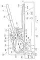
- FIG. 2 is a schematic longitudinal sectional view of the image reading apparatus 100 shown in FIG.
- FIG. 3 is a schematic perspective view of the image reading apparatus 100 shown in FIG.
- the image reading apparatus 100 shown in FIGS. 1 to 3 includes a configuration for reading a document image by fixing the document G by a document fixing method and a configuration for reading a document image by moving the document G by a document moving method.
- the image reading apparatus 100 illuminates the document G placed on the document table glass 201a with the light source unit 211 through the glass 201a, and illuminates the light source unit 211 in the sub-scanning direction (the arrow X direction in the figure).
- an automatic document feeder 300 The light source unit 211 illuminates the original G conveyed in the sub-scanning direction X so as to pass over the reading glass 201b through the glass 201b by the light source unit 211 located at a fixed position P in the original reading unit 200.
- FIG. 2 shows a state where the light source unit 211 is located at the fixed position P.
- the automatic document feeder 300, a mirror unit 203, which will be described later, and the like are not shown.
- the document reading unit 200 includes a document table glass 201a, a light source unit 210 (an example of an illumination device) including a light source unit 211, an optical system drive unit (not shown) that moves the light source unit 211, a mirror unit 203, a light collecting unit.
- An optical lens 204 and an image sensor (CCD here) 205 are provided.
- the light source unit 211 is provided in the light source unit 210. These are housed in a metal frame (hereinafter referred to as a frame) 202.
- the light source unit 210 will be described in detail later.
- the document table glass 201 a is made of a transparent glass plate, and both ends in the main scanning direction Y are placed on the frame body 202.
- the automatic document feeder 300 can be opened and closed with respect to the document reading unit 200 around an axis along the sub-scanning direction X (for example, supported by a hinge), and the lower surface thereof is the document of the document reading unit 200. It also serves as a document pressing member that presses the document G placed on the table glass 201a from above.
- the mirror unit 203 includes a second mirror 203a, a third mirror 203b, and a support member (not shown).
- the support member supports the second mirror 203a so that the light from the first mirror 230 in the light source unit 210 is reflected and guided to the third mirror 203b, and the third mirror 203b is supported from the second mirror 203a.
- the light is reflected and supported to the condenser lens 204.
- the condensing lens 204 condenses the light from the third mirror 203b on the image sensor 205.
- the image sensor 205 converts the light (original image light) from the condensing lens 204 into an electrical signal as image data.
- the optical system drive unit moves the light source unit 210 in the sub-scanning direction X at a constant speed, and similarly moves the mirror unit 203 in the sub-scanning direction X at a moving speed that is 1 ⁇ 2 of the moving speed of the light source unit 210. It is configured to move.
- the document reading unit 200 is compatible with a document moving method in addition to a document fixing method, and includes a document reading glass 201b. Therefore, the optical system driving unit is further configured to position the light source unit 210 at a predetermined home position P below the document reading glass 201b.
- the document table glass 201a and the document reading glass 201b are individually independent here, but they may be integrally formed.
- the automatic document feeder 300 includes a document tray 301 for placing the document G, a discharge tray 302 disposed below the document tray 301, and a first transport path 303 connecting the two.
- Two conveying roller pairs each of which includes an upstream conveying roller pair 304 and a downstream conveying roller pair 305 that convey an original G upstream and downstream in the conveying direction X1 of the original G with reference to the original reading glass 201b. It has. That is, the upstream conveyance roller pair 304, the document reading glass 201b, and the downstream conveyance roller pair 305 are arranged in this order along the conveyance direction X1.
- the document reading glass 201b is provided substantially horizontally so as to delineate the transport wall of the first transport path 303.
- the automatic document feeder 300 further includes a pickup roller 306, a roller roller 307, and a separation member 308 such as a separation pad.
- the pickup roller 306 feeds the document G placed on the document tray 301 from the document tray 301 into the first transport path 303 along the transport direction X1.
- the suction roller 307 is disposed downstream of the pickup roller 306 in the conveyance direction X1, and further conveys the original G sent by the pickup roller 306 together with the separating member 308 further downstream in the conveyance direction X1.
- the separating member 308 is configured to scoop (separate) the original G so that the original G conveyed between the separating roller 307 and the separating roller 307 is one sheet.
- the document G is conveyed between the separating roller 307 and the separating member 308 by the pickup roller 306, and the document G is separated by being separated and the separating roller 307 is rotationally driven.
- the sheets are conveyed one by one.
- the document G conveyed by the roller roller 307 can be guided along the first conveyance path 303 and supplied one by one toward the upstream conveyance roller pair 304.
- the pickup roller 306 can be brought into contact with and separated from the original G loaded on the original tray 301 by a pickup roller driving unit (not shown).
- the pickup roller 306 is coupled to the roller roller 307 so as to rotate in the same direction as the roller roller 307 via a drive transmission means 309 including an endless belt.
- the pickup roller 306 and the roller 307 are driven to rotate in a direction (arrow H in FIG. 2) in which the document G is transported in the transport direction X1 by a document supply driving unit (not shown). It has become.
- the automatic document feeder 300 can read one side of the original G by reversing the original G so that the front and back sides are reversed after conveying one side of the original G in a readable manner. It is configured to be able to be conveyed.
- the automatic document feeder 300 further includes a reverse roller pair 310, a second conveyance path 311, and a switching claw 312 in addition to the above configuration.
- the first conveyance path 303 is formed in a loop shape so as to convey the original G from the suction roller 307 to the upstream side conveyance roller pair 304, the original reading glass 201 b, the downstream side conveyance roller pair 305, and the reverse roller pair 310.
- the reverse roller pair 310 is disposed on the downstream side in the transport direction X1 with respect to the downstream side transport roller pair 305, and the document G transported from the downstream side transport roller pair 305 is rear end (upstream end in the transport direction X1). ) For transporting in front.
- the second conveyance path 311 is branched from a branching portion S1 between the reverse roller pair 310 and the downstream-side conveyance roller pair 305, and the original conveyed by the reverse roller pair 310 so that the rear end is in front.
- the G is guided upstream in the transport direction X1 from the upstream transport roller pair 304 of the first transport path 303.
- a switchback conveyance path 313 is formed between the reverse roller pair 310 of the first conveyance path 303 and the branch portion S1.
- the switchback conveyance path 313 is a conveyance path that can convey the original G by rotating the reverse roller pair 310 in the forward direction (conveyance direction X1 of the original G) and reversely convey the original G by rotating in the reverse direction. ing.
- the switching claw 312 is disposed at the branch portion S1 and has a first switching posture for guiding the document G from the reverse roller pair 310 to the upstream transport roller pair 304 via the second transport path 311 and downstream transport of the document G. It is configured to be able to take a second switching posture that leads from the roller pair 305 to the reverse roller pair 310 via the switchback conveyance path 313.
- the switching claw 312 is arranged in a form in which the switchback conveyance path 313 and the second conveyance path 311 are directly connected (first switching posture, see solid line in FIG. 2).
- first switching posture see solid line in FIG. 2
- the leading edge of the document G the end on the downstream side in the transport direction X1 pushes up the switching claw 312 to guide the document G to the switchback transport path 313.
- the second switching posture broken line in the figure.
- the branching claw 312 has a reversing roller such that the claw portion 312a falls by its own weight, closes the first conveying path 303 between the downstream conveying roller pair 305 and the reversing roller pair 310 and takes the first switching posture. It can be swung around a swing axis Q along the axial direction of the pair 311.
- the switching claw 312 has the rear end of the document G positioned in the switchback transport path 313, and the reverse of the transport direction X1 of the document G is reversed by the reverse roller pair 310 in which the document G rotates in the reverse direction.
- the document G is guided to the second transport path 311 when transported backward in the transport direction (arrow X2 direction in the figure).
- the size of the document G placed on the document tray 301 is detected by a document size sensor 314 provided in the document placement portion of the document tray 301. Presence / absence of the document G placed on the document tray 301 is detected by a document presence / absence detection sensor 315 disposed in the vicinity of the pickup roller 306 of the document placement portion of the document tray 301.
- the upstream-side transport roller pair 304 is adapted to abut and align the leading edge of the document G transported by the roller roller 307 in the stopped state, and is driven to rotate in accordance with the read timing.
- the original G thus transported is detected by a transport sensor 316 disposed downstream of the second transport path 311 and downstream of the upstream transport roller pair 304 in the transport direction X1 of the first transport path 303. It is like that.
- the document G discharged by the reverse roller pair 310 is detected by a discharge sensor 317 disposed near the reverse roller pair 310 on the discharge side of the reverse roller pair 310.
- the conveyance roller pairs 304 and 305, the reverse roller pair 310, and the like are driven by a conveyance system drive unit (not shown).
- the automatic document feeder 300 further includes a reading guide 318 facing the document reading glass 201b with the conveyed document G in between.
- the light source unit 210 emits light to the original G placed on the original table glass 201a.
- the image of the original G is scanned by moving to one side in the sub-scanning direction X at a constant speed while irradiating through 201a.
- the mirror unit 203 similarly moves to one side in the sub-scanning direction X at a movement speed that is 1 ⁇ 2 of the movement speed of the light source unit 210.
- the reflected light from the original G illuminated by the light source unit 210 is reflected by the first mirror 230 provided in the light source unit 210, and then subjected to 180 ° optical path conversion by the second and third mirrors 203a and 203b of the mirror unit 203. Is done.
- the light reflected from the third mirror 203b forms an image on the image sensor 205 via the condenser lens 204, where the original image light is read and converted into electrical image data.
- the automatic original feeder 300 keeps the light source unit 210 and the mirror unit 203 at the positions shown in FIG. It is conveyed to one side in the sub-scanning direction X so as to pass through the upper portion of the indicated position.
- the original G placed on the original tray 301 is taken out by the pickup roller 306, separated one by one by the separating roller 307 and the separating member 308, and conveyed to the first conveying path 303.
- the upstream transport roller pair 304 aligns the leading edge to prevent skew feeding and provides a prescribed reading. It is sent out at the timing, and the front and back sides are reversed and conveyed to the original reading glass 201b.
- the light from the light source unit 210 is irradiated on the one surface of the document G that has passed over the document reading glass 201b through the document reading glass 201b and reflected on the one surface.
- the light reflected from one surface of the original G is reflected by the first mirror 230 in the same manner as the original fixing method described above, and then the optical path is changed by 180 ° by the second and third mirrors 203a and 203b of the mirror unit 203. Is done.
- the light reflected from the third mirror 203b forms an image on the image sensor 205 via the condensing lens 204, where the document image is read and converted into electrical image data. Note that the reading operation by the image sensor 205 is the same in the case of double-sided reading to be described later, and will not be described below.
- the document G that has been read is pulled out from the reading glass 201 by the downstream-side conveyance roller pair 305, and is discharged through the switchback conveyance path 313 of the first conveyance path 303 by the reverse roller pair 310 that can be rotated reversibly. Discharged to the top.
- the original G on which one side is read is not discharged to the discharge tray 302, and the rear end of the original G is switched back.
- the reversing roller pair 310 that is transported so as to be positioned in the transport path 313, is reversely transported in the reverse transport direction X2 by the reverse roller pair 310 that rotates in the reverse direction, and is guided to the second transport path 311 by the switching claw 312 in the first switching posture. It is burned.
- the original G guided to the second conveyance path 311 returns to the first conveyance path 303 again via the second conveyance path 311, so that the front and back are reversed and conveyed by the upstream conveyance roller pair 304.
- the other surface is read through the document reading glass 201b.
- the original G that has been read on both sides is returned to the first conveyance path 303 again, so that the front and back are reversed and conveyed by the conveyance roller pairs 304 and 305, and then the switchback conveyance of the first conveyance path 303 is performed.
- the paper passes through the path 313 and is discharged to the discharge tray 302 via the reverse roller pair 310 rotating in the forward direction.
- the light source unit according to the embodiment of the present invention can be configured to include one or two or more light guide members.
- the light source unit 210 including two first and second light guide members 213a and 213b will be described below as an example.
- FIG. 4 is a schematic perspective view showing a schematic configuration of the light source unit 210 according to the present embodiment.
- FIG. 5 is a schematic perspective view showing the light source light guide member unit 220 in the light source unit 210.
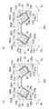
- FIG. 6 is a schematic diagram showing two light source substrates 2121 and 2122 in the light source unit 210.
- 6A shows a front view of each of the light source substrates 2121 and 2122
- FIG. 6B shows a side view of each of the light source substrates 2121 and 2122.
- the two light source boards 2121 and 2122 are members having the same configuration, and are shown in one drawing in FIG.
- reference C ⁇ b> 1 indicates the pedestal of each light source unit 211 a 1, 211 b 1, 211 a 2, 211 b 2
- reference C 2 indicates a connector terminal
- reference C 3 indicates a mounting screw hole for the light source substrate 2121, 2122. ing.
- FIG. 7 is a schematic side view of the main part of the light source unit 210 as viewed from both outer sides in the longitudinal direction.
- FIG. 7A shows a view seen from one outer side
- FIG. 7B shows a view seen from the other outer side.
- the pedestal C1, the connector terminal C2, and the mounting screw hole C3 are not shown.
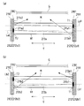
- FIG. 8 is a schematic cross-sectional view for explaining a light reflection state in the first and second light guide members 213a and 213b.
- FIG. 8A shows the light emitted from the light exit surface M to the original G by guiding the light from the two first light source portions 211a1 and 211a2 opposite to the light emitting surface from the longitudinal Y end surfaces 213a1 and 213a2. The reflection state is shown.
- FIG. 8B shows the light emitted from the light exit surface M to the original G by guiding the light from the two second light source portions 211b1 and 211b2 opposed to the light emitting surface from the longitudinal end Y end surfaces 213b1 and 213b2. The reflection state is shown.
- the glass provided between the document and the light source unit is not shown.
- the light source unit 210 includes two light source substrates 2121 and 2122, first and second light guide members 213a and 213b, a base 214, and first and second reflection members (here, reflection films) 215a and 215b. ing.
- one light source substrate 2121 is formed by integrally forming one first light source substrate 212a1 and one second light source substrate 212b1.
- One first light source substrate 212a1 is equipped with one first light source unit 211a1 that emits light to the first light guide member 213a.
- One second light source substrate 212b1 is equipped with one second light source unit 211b1 that emits light to the second light guide member 213b.
- the other light source substrate 2122 is formed by integrally forming the other first light source substrate 212a2 and the other second light source substrate 212b2 (see FIG. 6). ).
- the other first light source substrate 212a2 is mounted with the other first light source unit 211a2 that emits light to the first light guide member 213a.
- the other second light source substrate 212b2 is mounted with the other second light source part 211b2 that emits light to the second light guide member 213b.
- the light source unit corresponds to the member denoted by reference numeral 211 in FIG.
- one of the first and second light source units 211a1 and 211b1 and the other first and second light source unit 211a2 and 211b2 are both LED light source units composed of LED light emitting elements.
- the first and second light guide members 213a and 213b are both made of a light-transmitting material and are long and extend in the main scanning direction Y.
- the first and second light guide members 213a and 213b are arranged side by side in the sub-scanning direction X along the light irradiation surface of the document G at a predetermined interval so that the longitudinal direction Y is aligned with each other.
- the first light guide member 213a guides light from one first light source unit 211a1 from the longitudinal direction Y one end surface 213a1, and guides light from the other first light source unit 211a2 from the longitudinal direction Y other end surface 213a2.
- the original G is irradiated with light from a light exit surface (top surface) M extending in the longitudinal direction Y by being illuminated (see FIG. 8A).
- the second light guide member 213b guides light from one second light source unit 211b1 from the longitudinal direction Y one end surface 213b1, and guides light from the other second light source unit 211b2 from the longitudinal direction Y other end surface 213b2.
- the original G is irradiated with light from a light exit surface (top surface) M extending in the longitudinal direction Y by light (see FIG. 8B).
- each of the first and second light guide members 213a and 213b has a rectangular parallelepiped shape.
- both the first and second light guide members 213a and 213b are made of acrylic resin.
- the surfaces (bottom surfaces) of the first and second light guide members 213a and 213b located on the side opposite to the light exit surface M are the reflection surfaces N1.
- the reflection surface N1 is formed in a minute triangular shape (for example, a sawtooth shape) when viewed from the width directions Xa and Xb along the light emission surface M orthogonal to the longitudinal direction Y.
- the distance between the peaks of the reflective surface N1 formed in a triangular shape gradually decreases as it goes to the center in the longitudinal direction Y. ing.
- the base body 214 has one fixing portion that fixes one light source substrate 2121 on the first end surfaces 213 a 1 and 213 b 1 in the longitudinal direction of the first and second light guide members 213 a and 213 b.
- a screw hole for fixing with a screw SC here 2141 and the other fixing portion for fixing the other light source substrate 2122 on the side of the other end surface 212a2, 213b2 in the longitudinal direction of the first and second light guide members 213a, 213b (here. Screw holes 2142 fixed with screws SC).
- one of the first and second light source portions 211a1, 211b1 is placed on the longitudinal end surfaces 213a1, 213b1 of the first and second light guide members 213a, 213b, and the other first and second light source portions 211a2, 211b2 are placed.
- the base body 214 further includes a first support portion 214a that supports the first light guide member 213a, a second support portion 214b that supports the second light guide member 213b, a first support portion 214a, and a second support portion 214b. And a connecting portion 214c to be connected.
- a slit R extending along the longitudinal direction Y for allowing the reflected light from the document G to pass through is formed in the connecting portion 214c provided between the first support portion 214a and the second support portion 214b.
- the 1st support part 214a, the 2nd support part 214b, and the connection part 214c are comprised as the support plate 214d integrally formed here.
- each of the first and second support portions 214a and 214b is formed in a quadrangular shape with one side opened in a side view as viewed from the longitudinal direction Y. That is, the first and second support portions 214a and 214b are each configured such that a bottom plate extending in the longitudinal direction Y and the width direction Xa and Xb both ends along the light emission surface M orthogonal to the longitudinal direction Y of the bottom plate from the document G side. It consists of both side plates extending vertically or substantially vertically.
- the first and second support portions 214a and 214b are arranged side by side in the direction X along the light irradiation surface of the document G perpendicular to the longitudinal direction Y at a predetermined interval so that the longitudinal direction Y is aligned. .
- the first end of the open end of the square-shaped second support portion 214b on the side of the open side of the square-shaped first support portion 214a and the open side of the square-shaped second support portion 214b of the open side of the square-shaped side view.
- the supporting portion 214a side is connected by a connecting portion 214c, and one fixing portion 2141 is provided at one end of the both ends in the longitudinal direction Y of the connecting portion 214c, and the other fixing portion is provided at the other end.
- the first and second light guide members 213a and 213b are arranged so that the light emitted from the light emission surface M intersects the light irradiation surface of the document G (here, a side view as viewed from the longitudinal direction Y). And the incident angles of the light incident on the light irradiation surface of the original G are equal). Accordingly, here, the first and second support portions 214a and 214b are arranged so as to be separated from each other toward the base end side opposite to the open end in a side view as viewed from the longitudinal direction Y.
- the first reflecting member 215a mainly reflects light passing through the first light guide member 213a on the side surfaces N2 and N2 on both sides of the width direction Xa along the light exit surface M orthogonal to the longitudinal direction Y of the light guide member 213a. It is something to be made.
- the second reflecting member 215b mainly reflects light passing through the second light guide member 213b on the side surfaces N2 and N2 on both sides in the width direction Xb of the light guide member 213b (see FIG. 7).
- the first reflecting member 215a is disposed on a surface other than the both end faces 213a1, 213a2 and the light exit surface M of the first light guide member 213a.
- the second reflecting member 215b is disposed on a surface other than the both end surfaces 213b1, 213b2 and the light exit surface M of the second light guide member 213b.
- Each of the first and second reflecting members 215a and 215b is a reflecting film having a high reflectance (for example, Vicuity (registered trademark) DESR-M series having a high reflectance of 98% or more (manufactured by Sumitomo 3M)).
- Each of the first and second light guide members 213a and 213b is disposed on at least both side surfaces N2 and N2 of the reflection surface N1 and both side surfaces N2 and N2.
- the base body 214 further includes first and second holding members 216a and 216b that hold the first and second light guide members 213a and 213b, respectively.
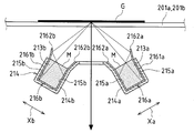
- FIG. 9 shows a reflection state of light that irradiates the document G from the inside of the first and second light guide members 213a and 213b held by the first and second holding members 216a and 216b of the base 214 through the light emission surface M. It is the schematic sectional drawing which looked at an example from the longitudinal direction Y one side.
- the first holding member 216a includes a first holding portion 2161a and a first inclined portion 2162a.
- maintains the 1st light guide member 213a so that attachment or detachment is possible.
- the first inclined portion 2162a reflects the light emitted from the light exit surface M of the first light guide member 213a, and light exit surface of the first holding portion 2161a so as to open obliquely as the distance from the first light guide member 213a increases. It extends from the tip on the M side.
- the second holding member 216b has a second holding portion 2161b and a second inclined portion 2162b.
- the second inclined portion 2162b reflects the light emitted from the light exit surface M of the second light guide member 213b and opens lightly as the distance from the second light guide member 213b increases. It extends from the tip on the M side.
- each of the first and second holding portions 2161a and 2161b is formed in a quadrangular shape with one side open in a side view as viewed from the longitudinal direction Y.
- the first and second holding portions 2161a and 2161b are each provided on the side of the document G from both ends of the bottom plate extending in the longitudinal direction Y and the width direction Xa and Xb along the light emission surface M orthogonal to the longitudinal direction Y of the bottom plate. It consists of both side plates extending vertically or substantially vertically.
- the first and second inclined portions 2162a and 2162b are formed so as to open obliquely as they move away from the first and second light guide members 213a and 213b in a side view as viewed from the longitudinal direction Y, respectively.
- the first and second holding portions 2161a and 2161b having a rectangular shape with one side opened in a side view are configured to detachably fit the first and second light guide members 213a and 213b on the inner surface, respectively.
- maintenance parts 2161a and 2161b can be reliably hold
- the first and second holding members 216a and 216b are detachably fitted into the first and second support portions 214a and 214b, respectively.
- the first and second light guide members 213a with respect to the first and second holding portions 2161a and 2161b in a state where the first and second holding members 216a and 216b are removed from the first and second support portions 214a and 214b, respectively. , 213b can be removed, so that the exchangeability of the first and second light guide members 213a, 213b can be improved accordingly.
- the first and second reflecting members 215a and 215b are supported by the first and second holding portions 2161a and 2161b, respectively.
- maintenance part 2161a, 2161b itself may be made into the 1st and 2nd reflection member 215a, 215b, respectively.
- the first and second holding portions 2161a and 2161b and the first and second inclined portions 2162a and 2162b can be made of a metal material such as stainless steel (SUS).
- the first and second holding portions 2161a and 2161b can also serve as the first and second reflecting members 215a and 215b, respectively.
- the inner surfaces of the first and second holding portions 2161a and 2161b can act as reflecting surfaces that reflect the light in the first and second light guide members 213a and 213b, respectively.
- the light source light guide member unit 220 includes first and second light guide members 213a and 213b, first and second holding members 216a and 216b, and a support plate 214d.
- the support plate 214d and the first and second holding members 216a and 216b may be integrally formed.
- a reflective film is affixed as the first reflecting member 215a to the inner surfaces of the first holding portion 2161a and the first inclined portion 2162a constituting the first holding member 216a.
- a reflective film is attached as the second reflecting member 215b to the inner surfaces of the second holding portion 2161b and the second inclined portion 2162b constituting the second holding member 216b.
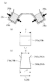
- FIG. 10 is a view for explaining the configuration of the first and second light guide members 213a and 213b held by the first and second holding members 216a and 216b of the base body 214.
- FIG. 10A shows a schematic cross-sectional view of the first and second holding members 216a and 216b and the first and second light guide members 213a and 213b as viewed from one side in the longitudinal direction Y.
- FIG. 10B shows a schematic side view of the first and second light guide members 213a and 213b viewed from the longitudinal direction Y.
- FIG. 10C is a schematic side view of the first and second holding members 216a and 216b as viewed from the longitudinal direction Y.
- FIG.10 (b) since the 1st and 2nd light guide members 213a and 213b are the same structures, it has shown in one figure. Further, in FIG. 10C, the first and second holding members 216a and 216b have the same configuration, and thus are shown in one drawing.
- the rectangular first and second holding portions 2161a and 2161b having one side opened in side view are both length ⁇ in the width direction Xa and Xb at the open ends. Specifically, about 4.8 mm) is shorter than the length ⁇ (specifically about 5.0 mm) in the width direction Xa, Xb at the base end.
- the ratio ( ⁇ / ⁇ ) of the length ⁇ of the width direction Xa, Xb at the open end to the length ⁇ of the width direction Xa, Xb at the base end of the first and second holding portions 2161a, 2161b is 0. About 96 can be exemplified. If this ratio ( ⁇ / ⁇ ) is too small, the first and second light guide members 213a and 213b are difficult to attach to and detach from the first and second holding portions 2161a and 2161b, respectively. On the other hand, the closer to 1, the lower the adhesion between the first and second holding portions 2161a and 2161b with the first and second light guide members 213a and 213b.
- the first and second light guide members 213a and 213b are each formed in a square shape or a rectangular shape as viewed from the side in the longitudinal direction Y.
- the first and second holding portions 2161a and 2161b are configured so that the length ⁇ in the width directions Xa and Xb at the open ends is first as shown in FIGS. 10 (b) and 10 (c).
- the second light guide members 213a and 213b are shorter than the length ⁇ (specifically, about 5.0 mm) in the width direction Xa and Xb.
- the ratio of the length ⁇ in the width direction Xa, Xb at the open end of the first and second holding portions 2161a, 2161b to the length ⁇ in the width direction Xa, Xb of the first and second light guide members 213a, 213b is about 0.96. If the ratio ( ⁇ / ⁇ ) is too small, the first and second light guide members 213a and 213b are difficult to attach to and detach from the first and second holding portions 2161a and 2161b, respectively. On the other hand, the closer to 1, the lower the adhesion between the first and second holding portions 2161a and 2161b with the first and second light guide members 213a and 213b.
- the first and second holding portions 2161a and 2161b are both made of a metal material having a spring property.
- the light source unit 210 further includes a first mirror 230 (see FIG. 2).
- the first mirror 230 is a support member (not shown) so that the light reflected by the light irradiation surface of the original G is guided to the second mirror 203a of the mirror unit 203 through the slit R provided in the connecting portion 214c of the base body 214. It is supported.
- the first and second holding portions 2161a and 2161b of the first and second holding members 216a and 216b hold the first and second light guide members 213a and 213b detachably (here, Fit). Therefore, even when the first and second light guide members 213a and 213b need to be replaced, the first and second light guide members 213a and 213b can be easily replaced with respect to the first and second holding members 216a and 216b, respectively. can do.
- the first and second inclined portions 2162a and 2162b of the first and second holding members 216a and 216b open obliquely as they move away from the first and second light guide members 213a and 213b, respectively.
- the first and second holding portions 2161a and 2161b are extended from the light emission surface M side tip. Therefore, the first and second light guide members 213a and 213b can be smoothly fitted into the first and second holding members 216a and 216b along the first and second inclined portions 2162a and 2162b. Further, in the light source unit 210, the first and second inclined portions 2162a and 2162b in the first and second holding members 216a and 216b are respectively guided from the light source portions 211a1, 211b1, 211a2, and 211b2 to the first and second light guides. Light emitted from the light exit surface M through the members 213a and 213b is reflected.
- the light from the light emission surface M can be effectively condensed on the light irradiation surface of the original G, and thereby the amount of irradiation light from the light emission surface M to the light irradiation surface of the original G can be reduced. Can be improved.
- the holding surfaces (inner surfaces here) of the first and second holding portions 2161a and 2161b act as reflecting surfaces that reflect the light in the first and second light guide members 213a and 213b. ing. Therefore, the reflection loss of light in the first and second light guide members 213a and 213b can be suppressed by the inner surfaces of the first and second holding portions 2161a and 2161b, respectively. It is possible to improve the amount of light irradiated onto the light irradiation surface.
- first and second reflecting members 215a and 215b are provided on the inner surfaces of the first and second holding portions 2161a and 2161b and the first and second inclined portions 2162a and 2162b, respectively. Therefore, reflection loss of light in the first and second light guide members 213a and 213b is suppressed by the first and second reflection members 215a and 215b provided on the inner surfaces of the first and second holding portions 2161a and 2161b, respectively. be able to. Further, the first and second reflecting members 215a and 215b provided on the inner surfaces of the first and second inclined portions 2162a and 2162b can suppress the reflection loss of the light emitted from the light emitting surface M, respectively. The amount of irradiation light from the light exit surface M to the light irradiation surface of the original G can be improved.
- first and second holding portions 2161a and 2161b hold the first and second light guide members 213a and 213b in close contact with the inner surfaces, respectively, so that the light guide members 213a and 213b Light leakage can be suppressed. Thereby, the reflection loss of the light in the light guide members 213a and 213b can be suppressed.
- the length ⁇ in the width direction Xa and Xb at the open end is greater than the length ⁇ in the width direction Xa and Xb at the base end. Further, the length is shorter than the length ⁇ in the width directions Xa and Xb of the first and second light guide members 213a and 213b. Accordingly, a force can be applied in the direction of the arrow in FIG. 10A, and the first and second light guide members 213a and 213b are securely held on the open ends of the first and second holding portions 2161a and 2161b, respectively. can do.
- the adhesion of the first and second light guide members 213a and 213b to the first and second holding portions 2161a and 2161b can be improved, and the light leakage of the light guide members 213a and 213b is suppressed accordingly. it can. Thereby, the loss of light in the light guide members 213a and 213b can be further suppressed.
- both the first and second holding portions 2161a and 2161b are made of a metal material having a spring property, the first and second holding portions 2161a of the first and second light guide members 213a and 213b are used. , 2161b can be further improved. Further, since the first and second holding portions 2161a and 2161b are elastically deformed when the first and second light guide members 213a and 213b are fitted, respectively, even if the light guide members 213a and 213b are repeatedly replaced, The light guide members 213a and 213b can be stably held over a long period of time.
- At least one of the first light source units 211a1 and 211a2 or at least one of the second light source units 211b1 and 211b2 may be configured as a light source group including two or more light sources (for example, LED elements). Good.
- one reflection member 2181 is interposed between one light source substrate 2121 and the first and second light guide members 213a and 213b.
- the other reflection member 2182 is interposed between the other light source substrate 2122 and the first and second light guide members 213a and 213b.
- one reflection member 2181 is attached to one fixing portion 2141 in a state where one end portion in the longitudinal direction Y of the support plate 214d is attached, and one light source substrate 2121 is disposed on the outside thereof.
- the other reflection member 2182 is attached to the other fixing portion 2142 with the other end Y in the longitudinal direction of the support plate 214d attached, and the other light source substrate 2122 is disposed outside the other reflection member 2182.
- the light source unit 210 further includes one heat radiating member 2191 and the other heat radiating member 2192.
- One heat radiating member 2191 is disposed in close contact with one reflecting member 2181 so as to surround one reflecting member 2181 and one light source substrate 2121.
- the other heat radiating member 2192 is disposed in close contact with the other reflecting member 2182 so as to surround the other reflecting member 2182 and the other light source substrate 2122.
- one heat radiating member 2191 is attached to the frame 210x of the light source unit 210 so as to be in close contact with both side surfaces of the one reflecting member 2181 and to surround the back surface of the one light source substrate 2121.
- the other heat radiating member 2192 is attached to the frame 210x of the light source unit 210 so as to be in close contact with both widthwise side surfaces of the other reflecting member 2182 and to surround the back surface of the other light source substrate 2122.
- each of the reflecting members 2181 and 2182 and each of the heat dissipating members 2191 and 2192 are made of a metal material such as aluminum.
- One reflection member 2181 is provided with a through hole T1 for allowing light from one of the first and second light source portions 211a1 and 211b1 to pass therethrough, and the other reflection member 2182 has the other first.
- a through hole T2 for allowing light from the first and second light source portions 211a2 and 211b2 to pass therethrough is provided.
- the reflection surface on the side of the one end surface 213a1, 213b1 in the longitudinal direction of the first and second light guide members 213a, 213b can be a reflection surface by one reflection member 2181.
- the other first and second light source portions 211a2 and 211b2 are introduced into the light guide members 213a and 213b through the longitudinal direction Y other end surfaces 213a2 and 213b2 of the first and second light guide members 213a and 213b, respectively. Since the reflected light (particularly the optical axes La2 and Lb2) is reflected by the reflecting surface of the one reflecting member 2181, the reflection efficiency can be further improved.
- the reflection surface on the side of the other end surface 213a2, 213b2 in the longitudinal direction of the first and second light guide members 213a, 213b can be used as a reflection surface by the other reflection member 2182.
- the first and second light source portions 211a1 and 211b1 are introduced into the light guide members 213a and 213b through the longitudinal direction Y end surfaces 213a1 and 213b1 of the first and second light guide members 213a and 213b. Since light (particularly the optical axes La1 and Lb1) is reflected by the reflecting surface of the other reflecting member 2182, the reflection efficiency can be further improved.
- the optical axes La1 and Lb1 of the first and second light source portions 211a1 and 211b1 and the optical axes La2 and Lb2 of the other first and second light source portions 211a2 and 211b2 are reflected in the light guide members 213a and 213b.
- the reflection loss at the time of reading can be further suppressed, and the amount of light that irradiates the light irradiation surface of the original G from the light exit surface M can be increased accordingly.
- one of the reflecting members 2181 and the other reflecting member 2182 is made of a metal material having excellent thermal conductivity, one of the first and second light source portions 211a1, 211b1 and the other The heat generated by the first and second light source units 211a2 and 211b2 can be effectively radiated by the reflecting members 2181 and 2182.
- each reflection member 2181,2182 may be comprised with the member excellent in thermal conductivity, such as a reflection film, and the metal members which support this reflection film.
- Image Reading Device 210 Light Source Unit (Example of Illumination Device) 211a1, 211b1 One first and second light source units 211a2, 211b2 The other first and second light source units 213a, 213b First and second light guide members 215a, 215b First and second reflecting members 216a, 216b First And second holding members 2161a, 2161b first and second holding portions 2162a, 2162b first and second inclined portions D image forming apparatus G original M which is a subject light exit surface Xa, Xb width direction Y longitudinal direction ⁇ of holding portion Length in the width direction at the U-shaped open end ⁇ Length in the width direction at the U-shaped base end of the holding portion ⁇ Length in the width direction of the light guide member
Landscapes
- Physics & Mathematics (AREA)
- Engineering & Computer Science (AREA)
- General Physics & Mathematics (AREA)
- Multimedia (AREA)
- Signal Processing (AREA)
- Optics & Photonics (AREA)
- General Engineering & Computer Science (AREA)
- Facsimile Scanning Arrangements (AREA)
- Light Sources And Details Of Projection-Printing Devices (AREA)
- Planar Illumination Modules (AREA)
- Facsimile Heads (AREA)
- Non-Portable Lighting Devices Or Systems Thereof (AREA)
Abstract
Description
(a)前記保持部は、長手方向から視た側面視で一辺が開放された四角形状に形成されていると共に、前記導光部材を前記保持部内面で着脱自在に嵌着保持しており、前記側面視一辺が開放された四角形状の保持部の開放端における幅方向の長さは、前記保持部の基端における幅方向の長さより短い態様、
(b)前記保持部は、長手方向から視た側面視で一辺が開放された四角形状に形成されていると共に、前記導光部材を前記保持部内面で着脱自在に嵌着保持しており、前記導光部材は、長手方向から視た側面視で正方形状又は長方形状に形成されており、前記側面視一辺が開放された四角形状の保持部の開放端における幅方向の長さは、前記導光部材の幅方向の長さより短い態様、
(c)前記(a)及び(b)を組み合わせた態様
である。
画像形成装置Dの装置本体D1は、露光装置1、現像装置2(2a,2b,2c,2d)、像担持体として作用する感光体ドラム3(3a,3b,3c,3d)、帯電器5(5a,5b,5c,5d)、クリーナ装置4(4a,4b,4c,4d)、転写部として作用する中間転写ローラ6(6a,6b,6c,6d)を含む中間転写ベルト装置8、定着装置12、シート搬送装置50、給紙部として作用する給紙トレイ10、及び排紙部として作用する排紙トレイ15を備えている。
図2は、図1に示す画像読取装置100の概略縦断面図である。図3は、図1に示す画像読取装置100の概略斜視図である。
本発明の実施形態に係る光源ユニットとして、一つ又は二つ以上の導光部材を備えたものとして構成することができる。ここでは、二つの第1及び第2導光部材213a,213bを備えた光源ユニット210を例にとって以下に説明する。
210 光源ユニット(照明装置の一例)
211a1,211b1 一方の第1及び第2光源部
211a2,211b2 他方の第1及び第2光源部
213a,213b 第1及び第2導光部材
215a,215b 第1及び第2反射部材
216a,216b 第1及び第2保持部材
2161a,2161b 第1及び第2保持部
2162a,2162b 第1及び第2傾斜部
D 画像形成装置
G 被写体である原稿
M 光射出面
Xa,Xb 幅方向
Y 長手方向
α 保持部のコ字状開放端における幅方向の長さ
β 保持部のコ字状基端における幅方向の長さ
γ 導光部材の幅方向の長さ
Claims (10)
- 光源部と、透光性を有する長尺な導光部材であって、前記光源部からの光を導光することで長手方向に沿った長尺な光射出面から被写体を照明する導光部材と、前記導光部材を保持する保持部材とを備えた照明装置において、
前記保持部材は、前記導光部材を着脱自在に保持する保持部と、前記光源部から前記導光部材を通して前記光射出面から射出される光を反射すると共に前記導光部材から遠ざかるに従って斜めに開くように前記保持部の前記光射出面側先端から延設された傾斜部とを有していることを特徴とする照明装置。 - 請求項1記載の照明装置において、
前記保持部の前記導光部材を保持する保持面は、前記導光部材内の光を反射させる反射面として作用することを特徴とする照明装置。 - 請求項1又は2記載の照明装置において、
前記保持部の前記導光部材を保持する保持面及び前記傾斜部の内面に反射部材が設けられていることを特徴とする照明装置。 - 請求項1から3の何れか一つに記載の照明装置において、
前記保持部は、前記導光部材を密着させた状態で保持していることを特徴とする照明装置。 - 請求項1から4の何れか一つに記載の照明装置において、
前記光源部は、前記導光部材の長手方向両側にそれぞれ設けられており、
前記導光部材は、一方の光源部からの光を長手方向一端面から導光すると共に、他方の光源部からの光を長手方向他端面から導光することで前記光射出面から被写体に光照射するものであることを特徴とする照明装置。 - 請求項5記載の照明装置において、
前記保持部は、長手方向から視た側面視で一辺が開放された四角形状に形成されていると共に、前記導光部材を前記保持部内面で着脱自在に嵌着保持しており、
前記側面視一辺が開放された四角形状の保持部の開放端における幅方向の長さは、前記保持部の基端における幅方向の長さより短いことを特徴とする照明装置。 - 請求項5又は6記載の照明装置において、
前記保持部は、長手方向から視た側面視で一辺が開放された四角形状形成されていると共に、前記導光部材を前記保持部内面で着脱自在に嵌着保持しており、
前記導光部材は、長手方向から視た側面視で正方形状又は長方形状に形成されており、
前記側面視一辺が開放された四角形状の保持部の開放端における幅方向の長さは、前記導光部材の幅方向の長さより短いことを特徴とする照明装置。 - 請求項1から7の何れか一つに記載の照明装置において、
前記保持部は、バネ性を有する金属材料で構成されていることを特徴とする照明装置。 - 請求項1から8の何れか一つに記載の照明装置を備えたことを特徴とする画像読取装置。
- 請求項9記載の画像読取装置を備えたことを特徴とする画像形成装置。
Priority Applications (6)
| Application Number | Priority Date | Filing Date | Title |
|---|---|---|---|
| CN200980142949.2A CN102197636B (zh) | 2008-10-30 | 2009-10-09 | 照明装置、图像读取装置及图像形成装置 |
| US13/062,745 US8787799B2 (en) | 2008-10-30 | 2009-10-09 | Illuminating device, image reading apparatus and image forming apparatus |
| US14/298,357 US9383082B2 (en) | 2008-10-30 | 2014-06-06 | Illuminating device, image reading apparatus and image forming apparatus |
| US15/171,350 US9948811B2 (en) | 2008-10-30 | 2016-06-02 | Illuminating device, image reading apparatus and image forming apparatus |
| US15/915,141 US10412254B2 (en) | 2008-10-30 | 2018-03-08 | Illuminating device, image reading apparatus and image forming apparatus |
| US16/526,730 US20190356809A1 (en) | 2008-10-30 | 2019-07-30 | Illuminating device, image reading apparatus and image forming apparatus |
Applications Claiming Priority (2)
| Application Number | Priority Date | Filing Date | Title |
|---|---|---|---|
| JP2008280075A JP4633159B2 (ja) | 2008-10-30 | 2008-10-30 | 照明装置、画像読取装置及び画像形成装置 |
| JP2008-280075 | 2008-10-30 |
Related Child Applications (2)
| Application Number | Title | Priority Date | Filing Date |
|---|---|---|---|
| US13/062,745 A-371-Of-International US8787799B2 (en) | 2008-10-30 | 2009-10-09 | Illuminating device, image reading apparatus and image forming apparatus |
| US14/298,357 Continuation US9383082B2 (en) | 2008-10-30 | 2014-06-06 | Illuminating device, image reading apparatus and image forming apparatus |
Publications (1)
| Publication Number | Publication Date |
|---|---|
| WO2010050353A1 true WO2010050353A1 (ja) | 2010-05-06 |
Family
ID=42128719
Family Applications (1)
| Application Number | Title | Priority Date | Filing Date |
|---|---|---|---|
| PCT/JP2009/067624 Ceased WO2010050353A1 (ja) | 2008-10-30 | 2009-10-09 | 照明装置、画像読取装置及び画像形成装置 |
Country Status (4)
| Country | Link |
|---|---|
| US (5) | US8787799B2 (ja) |
| JP (1) | JP4633159B2 (ja) |
| CN (2) | CN104010108B (ja) |
| WO (1) | WO2010050353A1 (ja) |
Families Citing this family (14)
| Publication number | Priority date | Publication date | Assignee | Title |
|---|---|---|---|---|
| JP4633159B2 (ja) | 2008-10-30 | 2011-02-16 | シャープ株式会社 | 照明装置、画像読取装置及び画像形成装置 |
| JP4757340B2 (ja) | 2009-10-30 | 2011-08-24 | シャープ株式会社 | 照明装置、その照明装置を備える画像読取り装置、その画像読取り装置を備える画像形成装置 |
| JP5538341B2 (ja) * | 2011-10-21 | 2014-07-02 | 京セラドキュメントソリューションズ株式会社 | 画像読取装置及び画像形成装置 |
| JP5900795B2 (ja) * | 2012-03-14 | 2016-04-06 | 富士ゼロックス株式会社 | 発光装置及び画像読取装置 |
| JP2014022974A (ja) * | 2012-07-19 | 2014-02-03 | Fuji Xerox Co Ltd | 画像読取装置及び画像形成装置 |
| EP2875446A4 (en) * | 2012-07-23 | 2016-09-28 | Hewlett Packard Development Co | CLASSIFICATION OF DOCUMENT |
| JP6359898B2 (ja) * | 2014-07-03 | 2018-07-18 | シャープ株式会社 | 照明装置、画像読取装置及びそれを備えた画像形成装置 |
| JP6889390B2 (ja) * | 2016-11-09 | 2021-06-18 | コニカミノルタ株式会社 | 画像読取装置 |
| JP7003646B2 (ja) * | 2017-12-26 | 2022-01-20 | 富士フイルムビジネスイノベーション株式会社 | 発光装置、画像読取装置、画像形成装置 |
| JP6563162B1 (ja) * | 2018-01-11 | 2019-08-21 | 三菱電機株式会社 | 画像読取装置 |
| JP2019216381A (ja) * | 2018-06-14 | 2019-12-19 | 京セラドキュメントソリューションズ株式会社 | 画像読取装置及びそれを備えた画像形成装置 |
| JP7181051B2 (ja) * | 2018-10-18 | 2022-11-30 | シャープ株式会社 | 原稿搬送装置および画像形成装置 |
| JP7329179B2 (ja) * | 2019-09-27 | 2023-08-18 | 京セラドキュメントソリューションズ株式会社 | 画像読取装置 |
| JP7537998B2 (ja) * | 2020-11-04 | 2024-08-21 | 株式会社ヴィーネックス | 光ラインセンサ |
Citations (4)
| Publication number | Priority date | Publication date | Assignee | Title |
|---|---|---|---|---|
| JPH097414A (ja) * | 1995-06-16 | 1997-01-10 | Sanyo Electric Co Ltd | 線状光源 |
| JPH10190960A (ja) * | 1996-12-27 | 1998-07-21 | Rohm Co Ltd | 線状光源装置およびこの線状光源装置を用いた画像読み取り装置 |
| JPH1155464A (ja) * | 1997-08-06 | 1999-02-26 | Rohm Co Ltd | 導光部材、この導光部材を用いた線状光源装置、および画像読み取り装置 |
| WO2006137263A1 (ja) * | 2005-06-21 | 2006-12-28 | Nippon Sheet Glass Company, Limited | イメージセンサ、画像読取装置及びイメージセンサの製造方法 |
Family Cites Families (12)
| Publication number | Priority date | Publication date | Assignee | Title |
|---|---|---|---|---|
| US3428397A (en) * | 1967-12-28 | 1969-02-18 | Dennison Mfg Co | Illumination in optical imaging apparatus |
| US5207504A (en) * | 1991-07-03 | 1993-05-04 | Swift Gerald R | Method and apparatus for tuning strip flourescent light fixtures |
| US6259082B1 (en) * | 1997-07-31 | 2001-07-10 | Rohm Co., Ltd. | Image reading apparatus |
| JP4087956B2 (ja) * | 1998-08-27 | 2008-05-21 | セイコーエプソン株式会社 | バックライトユニットおよび電子機器 |
| JP2002190917A (ja) * | 2000-12-20 | 2002-07-05 | Htt:Kk | 棒状光源装置及びこれを用いた光学式読取装置 |
| JP4721161B2 (ja) * | 2005-03-31 | 2011-07-13 | ミネベア株式会社 | 面状照明装置 |
| KR20070073275A (ko) * | 2006-01-04 | 2007-07-10 | 삼성전자주식회사 | 액정표시장치 |
| JP2008035036A (ja) | 2006-07-27 | 2008-02-14 | Kyocera Mita Corp | 画像読取装置及びこれを備えた画像形成装置 |
| JP2008172562A (ja) | 2007-01-12 | 2008-07-24 | Ricoh Co Ltd | 照明装置、画像読取装置、画像形成装置 |
| JP2009021158A (ja) * | 2007-07-13 | 2009-01-29 | Rohm Co Ltd | 線状光源装置 |
| US7954988B2 (en) * | 2007-07-31 | 2011-06-07 | Samung Electronics Co., Ltd. | Scanner module and image scanning apparatus employing the same |
| JP4633159B2 (ja) | 2008-10-30 | 2011-02-16 | シャープ株式会社 | 照明装置、画像読取装置及び画像形成装置 |
-
2008
- 2008-10-30 JP JP2008280075A patent/JP4633159B2/ja active Active
-
2009
- 2009-10-09 US US13/062,745 patent/US8787799B2/en active Active
- 2009-10-09 WO PCT/JP2009/067624 patent/WO2010050353A1/ja not_active Ceased
- 2009-10-09 CN CN201410171297.8A patent/CN104010108B/zh not_active Expired - Fee Related
- 2009-10-09 CN CN200980142949.2A patent/CN102197636B/zh not_active Expired - Fee Related
-
2014
- 2014-06-06 US US14/298,357 patent/US9383082B2/en active Active
-
2016
- 2016-06-02 US US15/171,350 patent/US9948811B2/en active Active
-
2018
- 2018-03-08 US US15/915,141 patent/US10412254B2/en active Active
-
2019
- 2019-07-30 US US16/526,730 patent/US20190356809A1/en not_active Abandoned
Patent Citations (4)
| Publication number | Priority date | Publication date | Assignee | Title |
|---|---|---|---|---|
| JPH097414A (ja) * | 1995-06-16 | 1997-01-10 | Sanyo Electric Co Ltd | 線状光源 |
| JPH10190960A (ja) * | 1996-12-27 | 1998-07-21 | Rohm Co Ltd | 線状光源装置およびこの線状光源装置を用いた画像読み取り装置 |
| JPH1155464A (ja) * | 1997-08-06 | 1999-02-26 | Rohm Co Ltd | 導光部材、この導光部材を用いた線状光源装置、および画像読み取り装置 |
| WO2006137263A1 (ja) * | 2005-06-21 | 2006-12-28 | Nippon Sheet Glass Company, Limited | イメージセンサ、画像読取装置及びイメージセンサの製造方法 |
Also Published As
| Publication number | Publication date |
|---|---|
| US20140285857A1 (en) | 2014-09-25 |
| CN104010108B (zh) | 2017-04-12 |
| CN102197636B (zh) | 2014-08-27 |
| JP2010109725A (ja) | 2010-05-13 |
| JP4633159B2 (ja) | 2011-02-16 |
| CN102197636A (zh) | 2011-09-21 |
| US8787799B2 (en) | 2014-07-22 |
| CN104010108A (zh) | 2014-08-27 |
| US9383082B2 (en) | 2016-07-05 |
| US9948811B2 (en) | 2018-04-17 |
| US10412254B2 (en) | 2019-09-10 |
| US20180198942A1 (en) | 2018-07-12 |
| US20110164413A1 (en) | 2011-07-07 |
| US20190356809A1 (en) | 2019-11-21 |
| US20160352954A1 (en) | 2016-12-01 |
Similar Documents
| Publication | Publication Date | Title |
|---|---|---|
| JP4633159B2 (ja) | 照明装置、画像読取装置及び画像形成装置 | |
| CN104394297B (zh) | 照明装置 | |
| CN102333172A (zh) | 图像读取装置和具备该图像读取装置的图像形成装置 | |
| JP2011176786A (ja) | 画像読取装置及びこれを備えた画像形成装置 | |
| JP4717107B2 (ja) | 照明装置、画像読取装置及び画像形成装置 | |
| JP2010183497A (ja) | 照明装置、画像読取装置及び画像形成装置 | |
| JP4901886B2 (ja) | 照明装置、画像読取装置及び画像形成装置 | |
| US8599447B2 (en) | Illuminating apparatus, image reading apparatus, and image forming apparatus | |
| CN102182956A (zh) | 照明装置、图像读取装置和图像形成装置 | |
| JP2010124118A (ja) | 画像読取装置及び画像形成装置 | |
| JP5143101B2 (ja) | 画像読取装置及び画像形成装置 | |
| JP5294219B2 (ja) | 画像読取装置及びこれを備えた画像形成装置 | |
| JP5302864B2 (ja) | 画像読取装置及びこれを備えた画像形成装置 | |
| JP5408537B2 (ja) | 画像読取装置及び画像形成装置 | |
| JP2010109726A (ja) | 照明装置、画像読取装置及び画像形成装置 | |
| JP2010191166A (ja) | 画像読取装置及び画像形成装置 | |
| JP2011125052A (ja) | 照度ムラ評価方法及び照度ムラ評価装置 |
Legal Events
| Date | Code | Title | Description |
|---|---|---|---|
| WWE | Wipo information: entry into national phase |
Ref document number: 200980142949.2 Country of ref document: CN |
|
| 121 | Ep: the epo has been informed by wipo that ep was designated in this application |
Ref document number: 09823466 Country of ref document: EP Kind code of ref document: A1 |
|
| WWE | Wipo information: entry into national phase |
Ref document number: 13062745 Country of ref document: US |
|
| NENP | Non-entry into the national phase |
Ref country code: DE |
|
| WWE | Wipo information: entry into national phase |
Ref document number: 3622/CHENP/2011 Country of ref document: IN |
|
| 122 | Ep: pct application non-entry in european phase |
Ref document number: 09823466 Country of ref document: EP Kind code of ref document: A1 |