WO2010047393A1 - 蒸気発生装置 - Google Patents
蒸気発生装置 Download PDFInfo
- Publication number
- WO2010047393A1 WO2010047393A1 PCT/JP2009/068280 JP2009068280W WO2010047393A1 WO 2010047393 A1 WO2010047393 A1 WO 2010047393A1 JP 2009068280 W JP2009068280 W JP 2009068280W WO 2010047393 A1 WO2010047393 A1 WO 2010047393A1
- Authority
- WO
- WIPO (PCT)
- Prior art keywords
- steam
- water
- water level
- steam generation
- hot water
- Prior art date
Links
Images


Classifications
-
- H—ELECTRICITY
- H05—ELECTRIC TECHNIQUES NOT OTHERWISE PROVIDED FOR
- H05B—ELECTRIC HEATING; ELECTRIC LIGHT SOURCES NOT OTHERWISE PROVIDED FOR; CIRCUIT ARRANGEMENTS FOR ELECTRIC LIGHT SOURCES, IN GENERAL
- H05B6/00—Heating by electric, magnetic or electromagnetic fields
- H05B6/02—Induction heating
- H05B6/10—Induction heating apparatus, other than furnaces, for specific applications
- H05B6/105—Induction heating apparatus, other than furnaces, for specific applications using a susceptor
- H05B6/108—Induction heating apparatus, other than furnaces, for specific applications using a susceptor for heating a fluid
-
- B—PERFORMING OPERATIONS; TRANSPORTING
- B24—GRINDING; POLISHING
- B24B—MACHINES, DEVICES, OR PROCESSES FOR GRINDING OR POLISHING; DRESSING OR CONDITIONING OF ABRADING SURFACES; FEEDING OF GRINDING, POLISHING, OR LAPPING AGENTS
- B24B49/00—Measuring or gauging equipment for controlling the feed movement of the grinding tool or work; Arrangements of indicating or measuring equipment, e.g. for indicating the start of the grinding operation
- B24B49/10—Measuring or gauging equipment for controlling the feed movement of the grinding tool or work; Arrangements of indicating or measuring equipment, e.g. for indicating the start of the grinding operation involving electrical means
- B24B49/105—Measuring or gauging equipment for controlling the feed movement of the grinding tool or work; Arrangements of indicating or measuring equipment, e.g. for indicating the start of the grinding operation involving electrical means using eddy currents
-
- F—MECHANICAL ENGINEERING; LIGHTING; HEATING; WEAPONS; BLASTING
- F01—MACHINES OR ENGINES IN GENERAL; ENGINE PLANTS IN GENERAL; STEAM ENGINES
- F01K—STEAM ENGINE PLANTS; STEAM ACCUMULATORS; ENGINE PLANTS NOT OTHERWISE PROVIDED FOR; ENGINES USING SPECIAL WORKING FLUIDS OR CYCLES
- F01K17/00—Using steam or condensate extracted or exhausted from steam engine plant
- F01K17/02—Using steam or condensate extracted or exhausted from steam engine plant for heating purposes, e.g. industrial, domestic
-
- F—MECHANICAL ENGINEERING; LIGHTING; HEATING; WEAPONS; BLASTING
- F22—STEAM GENERATION
- F22B—METHODS OF STEAM GENERATION; STEAM BOILERS
- F22B1/00—Methods of steam generation characterised by form of heating method
- F22B1/28—Methods of steam generation characterised by form of heating method in boilers heated electrically
- F22B1/281—Methods of steam generation characterised by form of heating method in boilers heated electrically other than by electrical resistances or electrodes
-
- F—MECHANICAL ENGINEERING; LIGHTING; HEATING; WEAPONS; BLASTING
- F22—STEAM GENERATION
- F22B—METHODS OF STEAM GENERATION; STEAM BOILERS
- F22B37/00—Component parts or details of steam boilers
- F22B37/02—Component parts or details of steam boilers applicable to more than one kind or type of steam boiler
- F22B37/26—Steam-separating arrangements
Definitions
- the present invention relates to a steam generator used for a steam convection oven or the like.
- Patent Document 1 discloses a steam production apparatus used for a food cooker or the like.
- This steam production apparatus is constituted by a vertical pipe body provided with an electromagnetic induction heating section, and a vertical boiler whose lower end portion is connected to a header section that commonly connects a water supply system and a drainage system, and the pipe body of the boiler
- a bypass pipe vertically connected to the tip of a steam outlet pipe extending laterally from the upper end of the pipe and a lower end thereof connected to the header section for detecting the water level in the boiler
- the bypass pipe is provided for dropping the hot water droplets contained in the steam generated in the vertical boiler to the header portion commonly connected to the water supply system and the drainage system.
- the apparatus it is difficult to incorporate the apparatus in a limited space together with the vertical boiler, and the apparatus cannot be reduced in size.
- the inside of the rising pipe arranged for detecting the water level in the boiler is heated by the hot water droplets returning to the header portion, so that it is provided in the rising pipe. There is a difficulty that the sensor for detecting the water level breaks down due to heating.
- the present invention provides a steam in which a steam passage part for discharging steam generated in the steam generating part upward is formed at the upper end of the steam generating part for storing a predetermined amount of water and generating steam.
- a heating vessel disposed inside the steam generation unit; and an induction heating coil wound around an outer periphery of the steam generation unit to generate heat from the heating unit, and generates heat by energizing the induction heating coil.
- an upper end of the steam passage section is disposed above the steam passage section.
- a steam outlet for receiving the steam discharged in the horizontal direction and deriving it in the lateral direction so that the water drops adhering to the top surface of the steam outlet drop and return directly to the steam generator. Steaming There is provided an apparatus.
- the steam generator configured as described above receives and drops a drop of water that rises due to the steam generated by the steam generator by the top surface of the steam outlet provided at the upper end of the steam passage, Since it directly recirculates to the steam generating part, it is possible to reduce the size by a simple structure without providing a separate bypass pipe for recirculating the water droplets that have risen together with the steam to the steam generating part. For this reason, for example, when the steam generator of the present invention is applied to a steam convection oven, it can be easily incorporated into a limited space in the side portion of the cooking chamber installed in the oven housing. Moreover, the thermal efficiency which generate
- the steam passage portion is provided with a water droplet shielding means for receiving the water droplet splashing from the steam generating portion, discharging only the steam upward, and allowing reflux of the water droplet falling from the steam outlet portion.
- a water droplet shielding plate provided with a plurality of through holes through which the steam discharged from the steam generating unit passes and a through hole through which the water droplets falling from the steam deriving unit flow down may be provided as the molten water shielding means. Good.
- the hot water droplet which jumps up from a steam generation part can be dropped exactly, and can be made to recirculate
- a water level detection tank provided with a water level sensor for detecting the water level in the steam generation unit is attached to the side of the steam generation unit, and the water level detection tank is connected to the induction heating coil. It is desirable to communicate with the steam generating part of the steam generating container at a position corresponding to the lower non-heat generating part.
- the water in the water level detection tank is not heated by the high-temperature hot water generated in the steam generation section, and there is no possibility that the water level sensor will break down due to heating.
- the water supplied from the water supply source flows into the steam generation unit via the water level detection tank, the water supplied to the water level detection tank does not stay and generation of scale can be suppressed.
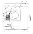
- FIG. 2 is a longitudinal sectional view taken along line AA in FIG. 1.
- FIG. 3 is a transverse sectional view taken along line BB in FIG. 1. It is a longitudinal cross-sectional view of a steam generator.
- the steam convection oven 10 includes a food cooking chamber 12 arranged in a housing 11, and a heater 13 provided in the cooking chamber 12 for heating the inside of the cooking chamber 12.
- the blower fan 14 provided in the cooking chamber 12 and the machine room 15 formed on the side of the cooking chamber 12 inside the housing 11 are incorporated in the cooking chamber 12.
- a steam generating device 20 for supplying steam.
- the steam generator 20 of the present invention stores steam generated inside the steam generator from the discharge port 32 a at the upper end of the steam generator 31 that stores a predetermined amount of water and generates steam.
- a cylindrical steam generation container 30 configured by a steam passage portion 32 to be discharged upward, a heating body 40 disposed inside the steam generation section 31 of the steam generation container 30, and wound around the outer periphery of the steam generation container 31
- an induction heating coil 50 that generates heat from the heating body 40, and steam generated by boiling water supplied into the steam generating section by the heating body 40 that generates heat by supplying power to the induction heating coil 50 is generated in the steam passage section. 32 is discharged.
- a steam outlet cylinder 70 is provided at the upper end of the steam passage portion 32 to receive the steam discharged upward from the steam passage portion and lead it out in the lateral direction. The water droplets adhering to the water fall and flow directly back to the steam generating section 31.
- the steam generation container 30 is made of a resin cylindrical member whose upper and lower sides are opened, and is provided on the floor surface of the machine room 15 and has a connecting cylinder 33 on a drain tank 16 used for discharging water in the cooking chamber 12. And a steam passage portion located above the substantially intermediate portion to generate a steam by heating a predetermined amount of water stored in the steam generating portion 31 located below the substantially intermediate portion.
- the steam generated in the steam generating section 31 from 32 is discharged upward.
- a first small diameter part 30a having a diameter smaller than the diameter from the upper part to the intermediate part, and a diameter smaller than the first small diameter part 30a located below the first small diameter part 30a.
- the second small-diameter portion 30b is formed, and tapered surfaces 30c and 30d are formed downward in portions to be the small-diameter portions 30a and 30b.
- the lower end portion of the steam generating container 30 is a drain port 31a, and a drain ball valve 34 is provided in the connecting tube 33 attached to the drain port 31a. When the drain ball valve 34 is opened, The water in the steam generation container 30 is discharged to the drain tank 16.
- a heating body 40 disposed inside the steam generation container 30 includes a heating rod 41 made of seven conductive metal rod-shaped members and an annular holder 42 that integrally fixes the lower ends of the seven heating rods 41. And a cylindrical holder 43 that holds the upper ends of the heating rods 41.
- the seven heating rods 41 are erected in the steam generating container 30 and are located at the same height as the winding position of the induction heating coil 50 and generate heat, and the lower side of the heating part 41a.
- the portion and the upper portion are non-heating portions 41b and 41c that do not generate heat.
- the holder 42 located at the lower end of the steam generating portion 31 is made of an annular resin member having a passage through which water passes at the center thereof, and holds the non-heat generating portion 41b of the lower portion of each heating rod 41 arranged in an annular shape. And fixed.
- the annular holder 42 is locked to a tapered surface 30 d formed between the first small diameter part 30 a and the second small diameter part 30 b located at the lower part of the steam generation container 30.
- the cylindrical holder 43 located at the upper end of the steam generating portion 31 is made of a resin member, and an annular recess 43a for holding the upper ends of the seven heating rods 41 is formed on the lower end surface thereof.
- the cylindrical holder 43 is fitted and fixed to the upper end portion of the steam generating container 30 with the non-heat generating portion 41c located on the upper side of the heating rod 41 engaged with the concave portion 43a.
- Ring-shaped resin brackets 35 and 36 are provided on the outer periphery of the intermediate portion in the vertical direction of the steam generating container 30 so as to be separated from each other in the vertical direction, and the induction heating coil 50 is wound between the brackets 35 and 36.
- the upper and lower brackets 35, 36 are provided with a plurality of rod-shaped ferrites 51 for preventing electromagnetic waves leaking from the induction heating coil 50 along the circumferential direction of the brackets 35, 36.
- the steam passage portion 32 of the steam generating container 30 is provided with a hot water droplet shielding portion 60 for preventing high temperature hot water droplets jumping up when steam is generated in the steam generating portion 31 from being discharged.
- the water droplet shielding part 60 is composed of three water droplet shielding plates 61 to 63 having a large number of through-holes, and these water droplet shielding plates 61 to 63 are arranged vertically on a cylindrical holder 43 that holds the upper end of the heating rod 41. They are mounted apart in the direction.
- Each of the hot water drop shielding plates 61 to 63 is formed with through holes 61a to 63a for allowing the hot water drops falling from the hot water drop separating cylinder portion 71 of the steam outlet tube 70 to pass through.
- the through holes 61a to 63a of the plate are arranged so as not to be superposed.
- the middle water droplet shielding plate 62 is formed with a single circular through hole 62 a at the center, and the middle and lower water droplet shielding plates 61, 63 have a middle water droplet shielding plate 62.
- a plurality of circular through holes 61a and 63a are formed at positions radially outside the through holes 62a.
- a steam outlet tube 70 is connected to the upper end of the steam passage portion 32 of the steam generating container 30 for leading the steam discharged from the discharge port 32a into the cooking chamber 12.
- the steam lead-out cylinder 70 branches from the middle of the hot water droplet separation cylinder portion 71 in a lateral direction, standing from the discharge port 32a of the steam generation container 30 and having its top surface closed. It consists of a steam outlet cylinder portion 72 whose outlet is connected to the steam inlet of the cooking chamber 12.
- the hot water droplet separating cylinder 71 receives steam that rises vigorously including hot water droplets from the discharge port 32a of the steam generation container 30 at its top surface and reduces its momentum. Drop and separate.
- the steam outlet cylinder 72 discharges the steam from which the hot water droplets have been separated by the hot water separator cylinder 71 from the outlet to the inside of the cooking chamber 12.
- a water level detection tank 80 is disposed on the side of the steam generation container 30.
- This water level detection tank 80 is erected in parallel with the steam generation section 31 at the side of the steam generation container 30 and corresponds to a non-heating section on the lower side of the induction heating coil 50 by a connecting pipe 82 provided at the lower portion thereof. It is connected to the steam generating part 32 of the steam generating container 30 at a position.
- the water level detection tank 80 is open to the atmosphere like the steam generation container 30, and the water level stored in the water level detection tank 80 is the same as the water level in the steam generation container 30.
- the water level detection tank 80 is provided with a float switch 81 as a water level sensor for detecting the water level inside the tank. In this embodiment, the float switch 81 detects the position which becomes the upper end of the heat generating part 41a of the heating rod 41 as the upper limit water level L1, and detects the water level below the upper limit water level L1 as the lower limit water level L2.
- the steam generator 20 includes water supply means 90 for supplying water to the steam generation container 30 through a water level detection tank 80.
- the water supply means 90 includes a water supply pipe 91 having one end connected to a water supply source such as water supply and the other end connected to the lower part of the water level detection tank 80.
- a water supply valve 92 that allows or blocks the passage of water is interposed in the water supply pipe 91, and the water supply valve 92 is attached to the drainage tank 16.
- the water supply valve 92 is released, the water supplied from the water supply source to the water supply pipe 91 flows into the water level detection tank 80 and also flows into the lower part of the steam generation container 30 through the connection pipe 82.
- the operation of the steam generator 20 configured as described above will be described.
- water supplied from a water supply source such as water supply flows into the water level detection tank 80 through the water supply pipe 91.
- the water flowing into the water level detection tank 80 is supplied into the steam generation container 30 through the connection pipe 82.
- the water supply valve 92 is closed and the supply of water to the steam generating container 30 is temporarily interrupted.
- the water level in the steam generation container 30 is the same as the water level in the water level detection tank and is located at the upper end of the heat generating portion 41a of the heating rod 41.
- steam generation processing for supplying steam into the cooking chamber 12 is executed.
- a high frequency current is applied to the induction heating coil 50 to cause the heating body 40 to generate heat, and the water in the steam generation container 30 is boiled by the heat generation of the heating body 40 to generate steam.
- Steam generated in the steam generation section 31 of the steam generation container 30 rises up the steam passage section 32 and is discharged from the discharge port 32a, and is introduced into the cooking chamber 12 through the steam outlet tube 70.
- the steam generated in the steam generation portion 31 passes through each of the hot water droplet shielding plates 61 to 63.
- the steam passes through each of the through holes 61a to 63a and rises in the steam passage portion 32, but the hot water splashed when the steam is generated in the steam generation portion 31 is received by the water droplet shielding plates 61 to 63 and is passed through the steam passage portion 32. No discharge from the discharge port 32a.
- the water in the water level detection tank 80 flows into the steam generation container 30 through the connection pipe 82.
- the water level in the water level detection tank 80 reaches a predetermined lower limit water level L2
- the float switch 81 that the lower limit water level L2 is reached
- the water supply valve 92 is opened, and water supply is started.
- the water supply valve 92 is opened, the water level in the water level detection tank 80 rises, and the water level in the steam generation container 30 rises due to water flowing from the water level detection tank 80 through the connection pipe 82.
- the water supply valve 92 is closed, and the water supply is interrupted.
- the water supply is controlled so that the water level in the steam generation container 30 becomes the water level between the lower limit water level L2 and the upper limit water level L1.
- a drainage process for draining water from the steam generation container 30 is executed.
- the supply of high-frequency current to the induction heating coil 50 is stopped, the water supply valve 92 is closed, and the drainage ball valve 34 is opened.
- the drainage ball valve 34 is opened, the water in the steam generating container 30 flows into the drainage tank 16 through the drainage port 31a, and the water that has flowed into the drainage tank 16 is discharged to the outside of the steam convection oven 10. .
- the drain port 31a at the lower end of the steam generation container 30 is provided directly below the heating body 40, water does not remain in the steam generation container 30, and the scale due to the chalk component in the steam generation container 30 Occurrence is suppressed.
- the steam generator configured as described above receives a drop of water that rises due to the force of steam generated in the steam generator 31 by the drop separator cylinder 71 of the steam outlet cylinder 70 provided at the upper end of the steam passage 32. Since it falls and directly recirculates to the steam generation part 31, it is reduced in size by a simple structure without providing a separate bypass line or the like for recirculating the water droplets rising together with the steam to the steam generation part 31. I can. For this reason, for example, when the steam generator of the present invention is applied to a steam convection oven, it can be easily incorporated into a limited space in the side portion of the cooking chamber installed in the oven housing. Moreover, the thermal efficiency which generate
- a plurality of through-holes through which steam discharged from the steam generating unit 31 passes and steam outlet cylinders serve as a hot water drop shielding means that receives the steam splashing from the steam generating unit 31 in the steam passage unit 32 and discharges only the steam upward.
- a water level detection tank 80 provided with a float switch 81 as an inside water level sensor for detecting the water level in the steam generation unit 31 is attached to the side of the steam generation unit 31, and the water level detection tank 80 is placed under the induction heating coil.
- the water in the water level detection tank 80 is heated by the hot water generated in the steam generating unit 31 by communicating with the steam generating unit 31 of the steam generating container 30 at a position corresponding to the non-heat generating part on the side. There is no possibility that the float switch 81 malfunctions due to heating.
Landscapes
- Engineering & Computer Science (AREA)
- Mechanical Engineering (AREA)
- General Engineering & Computer Science (AREA)
- Physics & Mathematics (AREA)
- Thermal Sciences (AREA)
- Combustion & Propulsion (AREA)
- Chemical & Material Sciences (AREA)
- Electromagnetism (AREA)
- Life Sciences & Earth Sciences (AREA)
- Sustainable Development (AREA)
- Sustainable Energy (AREA)
- Cookers (AREA)
- General Induction Heating (AREA)
- Commercial Cooking Devices (AREA)
Abstract
Description
Claims (4)
- 所定量の水を貯えて蒸気を発生させる蒸気発生部の上端に同蒸気発生部の内部に発生した蒸気を上方に吐出させる蒸気通路部を形成した蒸気発生容器と、前記蒸気発生部の内部に配置した加熱体と、前記蒸気発生部の外周に巻回されて前記加熱体を発熱させる誘導加熱コイルとを備えて、前記誘導加熱コイルの通電により発熱した前記加熱体によって前記蒸気発生部内に供給された水が沸騰して生じた蒸気が前記蒸気通路部から吐出するようにした蒸気発生装置において、
前記蒸気通路部の上端に同蒸気通路部から上方に吐出する蒸気を受け止めて横方向に導出する蒸気導出部を設けて、同蒸気導出部の天面に付着した湯滴が落下して前記蒸気発生部に直接還流するようにしたことを特徴とする蒸気発生装置。 - 前記蒸気通路部に前記蒸気発生部から跳ね上がる熱湯を受け止めて蒸気のみを噴出させ前記蒸気導出部から落下する湯滴に還流を許容する湯滴遮蔽手段を設けたことを特徴とする請求項1に記載の蒸気発生装置。
- 前記湯滴遮蔽手段として、前記蒸気発生部から吐出する蒸気が通過する複数の貫通孔と前記蒸気導出部から落下する湯滴が通過する貫通孔を有する湯滴遮蔽板を設けたことを特徴とする請求項2に記載の蒸気発生装置。
- 前記蒸気発生容器の側部に前記蒸気発生部内の水位を検知する水位センサをその内部に設けた水位検知タンクを付設して、同水位検知タンクを前記誘導加熱コイルの下側の非発熱部に対応する位置にて前記蒸気発生容器の蒸気発生部に連通させたことを特徴とする請求項1に記載の蒸気発生装置。
Priority Applications (3)
| Application Number | Priority Date | Filing Date | Title |
|---|---|---|---|
| EP09822090.8A EP2360432B1 (en) | 2008-10-23 | 2009-10-23 | Steam generator |
| CN2009801425383A CN102216684A (zh) | 2008-10-23 | 2009-10-23 | 蒸汽发生装置 |
| US13/125,861 US9253824B2 (en) | 2008-10-23 | 2009-10-23 | Steam generator |
Applications Claiming Priority (2)
| Application Number | Priority Date | Filing Date | Title |
|---|---|---|---|
| JP2008273601A JP5315000B2 (ja) | 2008-10-23 | 2008-10-23 | 蒸気発生装置 |
| JP2008-273601 | 2008-10-23 |
Publications (1)
| Publication Number | Publication Date |
|---|---|
| WO2010047393A1 true WO2010047393A1 (ja) | 2010-04-29 |
Family
ID=42119429
Family Applications (1)
| Application Number | Title | Priority Date | Filing Date |
|---|---|---|---|
| PCT/JP2009/068280 WO2010047393A1 (ja) | 2008-10-23 | 2009-10-23 | 蒸気発生装置 |
Country Status (5)
| Country | Link |
|---|---|
| US (1) | US9253824B2 (ja) |
| EP (1) | EP2360432B1 (ja) |
| JP (1) | JP5315000B2 (ja) |
| CN (1) | CN102216684A (ja) |
| WO (1) | WO2010047393A1 (ja) |
Cited By (1)
| Publication number | Priority date | Publication date | Assignee | Title |
|---|---|---|---|---|
| WO2013014023A1 (en) * | 2011-07-25 | 2013-01-31 | Total S.A. | Steam generation |
Families Citing this family (15)
| Publication number | Priority date | Publication date | Assignee | Title |
|---|---|---|---|---|
| JP5765994B2 (ja) * | 2011-03-31 | 2015-08-19 | ホシザキ電機株式会社 | 蒸気発生装置 |
| JP5743660B2 (ja) * | 2011-04-08 | 2015-07-01 | ホシザキ電機株式会社 | 蒸気発生装置 |
| JP5743677B2 (ja) * | 2011-04-25 | 2015-07-01 | ホシザキ電機株式会社 | 蒸気発生装置 |
| KR200463799Y1 (ko) * | 2012-07-20 | 2012-11-26 | 왕한기 | 증기 생산용 고주파 유도가열 보일러 |
| JP6000911B2 (ja) * | 2013-07-10 | 2016-10-05 | ホシザキ株式会社 | 蒸気発生装置 |
| CN105403659A (zh) * | 2015-12-16 | 2016-03-16 | 济南海能仪器股份有限公司 | 凯氏定氮仪蒸汽发生器装置 |
| CN105510611A (zh) * | 2015-12-16 | 2016-04-20 | 济南海能仪器股份有限公司 | 全自动分析仪的控制系统 |
| CN105615629A (zh) * | 2016-02-22 | 2016-06-01 | 北京利仁科技股份有限公司 | 一种连通有水位监测室的蒸汽发生器 |
| TW201731430A (zh) * | 2016-02-25 | 2017-09-16 | Panasonic Ip Man Co Ltd | 感應加熱調理器及烤盤 |
| TWI757284B (zh) * | 2016-05-03 | 2022-03-11 | 義大利商瑞亞梵朵斯服務公司 | 用於製備和分配飲料的設備和方法 |
| CN111052859B (zh) * | 2017-09-06 | 2022-07-26 | Jt国际公司 | 用于蒸气产生装置的感应加热组件 |
| CN108180456B (zh) * | 2017-12-20 | 2019-11-05 | 宣城市水阳三宝食品有限公司 | 一种具有自动进水功能的双重加热式蒸汽锅炉 |
| US11396789B2 (en) | 2020-07-28 | 2022-07-26 | Saudi Arabian Oil Company | Isolating a wellbore with a wellbore isolation system |
| US11136868B1 (en) | 2020-09-03 | 2021-10-05 | Saudi Arabian Oil Company | Aqueous flash treatment in well applications |
| US11624265B1 (en) | 2021-11-12 | 2023-04-11 | Saudi Arabian Oil Company | Cutting pipes in wellbores using downhole autonomous jet cutting tools |
Citations (3)
| Publication number | Priority date | Publication date | Assignee | Title |
|---|---|---|---|---|
| JPH05231601A (ja) * | 1992-02-18 | 1993-09-07 | Matsushita Electric Ind Co Ltd | 蒸気発生装置 |
| JPH1194203A (ja) | 1997-09-24 | 1999-04-09 | Seda Giken:Kk | 蒸気製造装置 |
| JP2003021303A (ja) * | 2001-07-06 | 2003-01-24 | Nakanishi Mfg Co Ltd | 過熱蒸気発生装置 |
Family Cites Families (50)
| Publication number | Priority date | Publication date | Assignee | Title |
|---|---|---|---|---|
| US2407562A (en) * | 1942-08-17 | 1946-09-10 | Einar G Lofgren | Induction heater |
| US2427361A (en) * | 1944-10-09 | 1947-09-16 | Einar G Lofgren | Electrical induction boiler |
| US2573719A (en) * | 1948-05-26 | 1951-11-06 | Everedy Company | Regulating valve for cooking utensil covers |
| US3190997A (en) * | 1961-02-16 | 1965-06-22 | Transcontinental Electronics C | Heating apparatus |
| CA955635A (en) * | 1969-03-10 | 1974-10-01 | Donald F. Othmer | System for electrically heating a fluid being transported in a pipe |
| US4341936A (en) * | 1979-12-17 | 1982-07-27 | Virgin George C | Electromagnetic induction energy converter |
| US4503305A (en) * | 1979-12-17 | 1985-03-05 | Virgin George C | Electromagnetic induction air heater |
| SE442696B (sv) * | 1981-09-24 | 1986-01-20 | Asea Ab | Anordning for vermning av gas- eller vetskeformiga media |
| JPS6110401U (ja) * | 1984-06-26 | 1986-01-22 | 株式会社日立ホームテック | 蒸気発生装置 |
| CA1253556A (fr) * | 1986-10-01 | 1989-05-02 | Richard J. Marceau | Un chauffe-fluide comprenant un noyau magnetique non conducteur ayant un enroulement primaire de fils conducteurs d'electricite |
| US4814567A (en) * | 1987-07-08 | 1989-03-21 | Darko Jorge Lazaneo Dragicevic | Electro-thermic resonance system for heating liquid |
| JPH01129506U (ja) * | 1988-02-26 | 1989-09-04 | ||
| JPH0711291Y2 (ja) * | 1989-02-18 | 1995-03-15 | 三浦工業株式会社 | 多管式貫流ボイラーの気水分離構造 |
| JPH04230987A (ja) * | 1990-06-18 | 1992-08-19 | Nikko Kk | 電磁誘導加熱器 |
| JPH06104170B2 (ja) * | 1991-10-16 | 1994-12-21 | アスカ工業株式会社 | フィルター容器 |
| US5286942A (en) * | 1991-10-24 | 1994-02-15 | Arthur D. Little Enterprises, Inc. | Induction steam humidifier |
| US5523550A (en) * | 1992-01-06 | 1996-06-04 | Kimura; Todd T. | Capacitive induction heating method and apparatus for the production for instant hot water and steam |
| US5222185A (en) * | 1992-03-26 | 1993-06-22 | Mccord Jr Harry C | Portable water heater utilizing combined fluid-in-circuit and induction heating effects |
| JPH06208887A (ja) * | 1992-07-27 | 1994-07-26 | Haidetsuku Kk | 電磁誘導加熱蒸気発生器 |
| US5655212A (en) * | 1993-03-12 | 1997-08-05 | Micropyretics Heaters International, Inc. | Porous membranes |
| AU698049B2 (en) * | 1994-10-24 | 1998-10-22 | Matsushita Electric Industrial Co., Ltd. | Steam generating apparatus of induction heating system |
| JPH08264272A (ja) * | 1995-03-27 | 1996-10-11 | Seta Giken:Kk | 電磁誘導加熱装置 |
| JPH09145009A (ja) * | 1995-11-28 | 1997-06-06 | Mitsubishi Heavy Ind Ltd | 気水分離器 |
| US5781581A (en) * | 1996-04-08 | 1998-07-14 | Inductotherm Industries, Inc. | Induction heating and melting apparatus with superconductive coil and removable crucible |
| US5773797A (en) * | 1996-10-18 | 1998-06-30 | Daihan, Co., Ltd. | Induction heated steam generating system |
| WO1998041336A1 (fr) * | 1997-03-17 | 1998-09-24 | Kabushiki Kaisha Seta Giken | Appareil et procede de nettoyage |
| JPH10311505A (ja) * | 1997-05-15 | 1998-11-24 | Ebara Boiler Kk | 多管式貫流ボイラーの気水分離装置 |
| DE69810308T2 (de) * | 1997-08-19 | 2003-08-14 | Shell Int Research | Vorrichtung zum amorphen verbinden von rohren |
| US5869812A (en) * | 1997-09-12 | 1999-02-09 | Middleby-Marshall, Inc. | Pressure regulator for steam oven |
| US6107605A (en) * | 1997-09-12 | 2000-08-22 | Middleby-Marshall, Inc. | Pressure regulator for steam oven |
| US5873298A (en) * | 1998-06-23 | 1999-02-23 | Chang; Kwei-Tang | Dual-function filter type pot cover |
| JP4172560B2 (ja) * | 1998-12-28 | 2008-10-29 | 日本サルヴ▲ヱ▼ージ株式会社 | 液体物質回収方法、および液体物質回収装置 |
| US6335517B1 (en) * | 1999-05-28 | 2002-01-01 | The Holmes Group, Inc. | Humidifier having induction heating system |
| US6307193B1 (en) * | 2000-08-02 | 2001-10-23 | Microwave Magic Company, Inc. | Cooking vessel with adjustable ventilation system |
| US20020153369A1 (en) * | 2001-04-23 | 2002-10-24 | Daihan Corporation | Induction fluid heating system |
| JP4087116B2 (ja) | 2002-01-18 | 2008-05-21 | Tdk株式会社 | 成形体の製造方法及び成形体の製造装置 |
| JP3827303B2 (ja) * | 2002-03-12 | 2006-09-27 | 松下電器産業株式会社 | 蒸気発生機能付き高周波加熱装置 |
| ATE445125T1 (de) * | 2002-04-02 | 2009-10-15 | Masami Nomura | Erzeuger von überhitztem dampf |
| US6906296B2 (en) * | 2002-06-12 | 2005-06-14 | Steris Inc. | Electromagnetically responsive heating apparatus for vaporizer |
| US6734405B2 (en) * | 2002-06-12 | 2004-05-11 | Steris Inc. | Vaporizer using electrical induction to produce heat |
| US6967315B2 (en) * | 2002-06-12 | 2005-11-22 | Steris Inc. | Method for vaporizing a fluid using an electromagnetically responsive heating apparatus |
| US6904903B1 (en) * | 2002-07-22 | 2005-06-14 | Middleby-Marshall, Inc. | Convection steamer with forced recirculation through steam bath |
| US6622616B1 (en) * | 2002-11-18 | 2003-09-23 | Dutro Company | Poultry roaster |
| US20040250690A1 (en) * | 2003-01-09 | 2004-12-16 | Thomas Restis | Cooking vessel and lid therefor |
| JP4187613B2 (ja) * | 2003-08-27 | 2008-11-26 | シャープ株式会社 | 蒸気発生装置及びそれを備えた加熱調理器 |
| JP4143555B2 (ja) * | 2004-02-13 | 2008-09-03 | 株式会社パイコーポレーション | 過熱蒸気発生装置 |
| US20060243141A1 (en) * | 2005-05-02 | 2006-11-02 | Loan Mayer | Food Container, Strainer, Cooker, and Strained Liquid Collector |
| JP3876267B1 (ja) | 2005-08-01 | 2007-01-31 | シャープ株式会社 | 加熱調理器 |
| JP2008064367A (ja) * | 2006-09-06 | 2008-03-21 | Fuji Electric Systems Co Ltd | 誘導加熱式蒸気発生装置 |
| JP4917999B2 (ja) * | 2007-09-03 | 2012-04-18 | 賢一 馬面 | スチーム発生装置 |
-
2008
- 2008-10-23 JP JP2008273601A patent/JP5315000B2/ja active Active
-
2009
- 2009-10-23 US US13/125,861 patent/US9253824B2/en not_active Expired - Fee Related
- 2009-10-23 WO PCT/JP2009/068280 patent/WO2010047393A1/ja active Application Filing
- 2009-10-23 CN CN2009801425383A patent/CN102216684A/zh active Pending
- 2009-10-23 EP EP09822090.8A patent/EP2360432B1/en not_active Not-in-force
Patent Citations (3)
| Publication number | Priority date | Publication date | Assignee | Title |
|---|---|---|---|---|
| JPH05231601A (ja) * | 1992-02-18 | 1993-09-07 | Matsushita Electric Ind Co Ltd | 蒸気発生装置 |
| JPH1194203A (ja) | 1997-09-24 | 1999-04-09 | Seda Giken:Kk | 蒸気製造装置 |
| JP2003021303A (ja) * | 2001-07-06 | 2003-01-24 | Nakanishi Mfg Co Ltd | 過熱蒸気発生装置 |
Non-Patent Citations (1)
| Title |
|---|
| See also references of EP2360432A4 * |
Cited By (3)
| Publication number | Priority date | Publication date | Assignee | Title |
|---|---|---|---|---|
| WO2013014023A1 (en) * | 2011-07-25 | 2013-01-31 | Total S.A. | Steam generation |
| FR2978527A1 (fr) * | 2011-07-25 | 2013-02-01 | Total Sa | Generation de vapeur |
| CN103717968A (zh) * | 2011-07-25 | 2014-04-09 | 道达尔公司 | 蒸汽的发生 |
Also Published As
| Publication number | Publication date |
|---|---|
| CN102216684A (zh) | 2011-10-12 |
| JP5315000B2 (ja) | 2013-10-16 |
| US9253824B2 (en) | 2016-02-02 |
| US20120037145A1 (en) | 2012-02-16 |
| EP2360432A4 (en) | 2013-09-11 |
| EP2360432B1 (en) | 2016-11-30 |
| EP2360432A1 (en) | 2011-08-24 |
| JP2010101564A (ja) | 2010-05-06 |
Similar Documents
| Publication | Publication Date | Title |
|---|---|---|
| WO2010047393A1 (ja) | 蒸気発生装置 | |
| JP2010121803A (ja) | 蒸気発生装置 | |
| JP5308222B2 (ja) | 蒸気発生装置 | |
| US20150047514A1 (en) | Heating cooker | |
| US20190380524A1 (en) | Modular steamer accessory for steam-heating and/or steam-cooking food contained in a container | |
| RU2531415C2 (ru) | Варочное устройство | |
| EP3553392B1 (en) | Cooking appliance | |
| JP2000266302A (ja) | 蒸気発生器 | |
| RU2470104C2 (ru) | Парогенератор с секцией для подогрева воды | |
| JP5809441B2 (ja) | 蒸気発生装置 | |
| JP5367438B2 (ja) | 蒸気発生装置 | |
| KR20130129402A (ko) | 이중 수조를 갖는 온수 기반 음료 준비용 가전기기 | |
| CN108443853A (zh) | 蒸汽发生装置及蒸汽家电 | |
| JP2006112746A (ja) | 蒸気発生装置 | |
| CN208204962U (zh) | 蒸汽发生装置及蒸汽家电 | |
| CN212481230U (zh) | 电热型智能蒸汽发生箱 | |
| TWI556779B (zh) | A delayed drip-type steam generator and a food-making device based on the generator | |
| JP2015132465A (ja) | 蒸気発生装置 | |
| EP2881660B1 (en) | Centrifugal separator of fluid and vapour with a household apparatus | |
| JP5722918B2 (ja) | 急速湯沸かし器およびその湯沸かし器を備える家庭電化製品 | |
| JP6000911B2 (ja) | 蒸気発生装置 | |
| JP2014042767A (ja) | 蒸気滅菌器 | |
| JP5743660B2 (ja) | 蒸気発生装置 | |
| JP2008032266A (ja) | 蒸気発生装置及びこれを搭載した加熱調理器 | |
| JP5765994B2 (ja) | 蒸気発生装置 |
Legal Events
| Date | Code | Title | Description |
|---|---|---|---|
| WWE | Wipo information: entry into national phase |
Ref document number: 200980142538.3 Country of ref document: CN |
|
| 121 | Ep: the epo has been informed by wipo that ep was designated in this application |
Ref document number: 09822090 Country of ref document: EP Kind code of ref document: A1 |
|
| NENP | Non-entry into the national phase |
Ref country code: DE |
|
| REEP | Request for entry into the european phase |
Ref document number: 2009822090 Country of ref document: EP |
|
| WWE | Wipo information: entry into national phase |
Ref document number: 2009822090 Country of ref document: EP |
|
| WWE | Wipo information: entry into national phase |
Ref document number: 13125861 Country of ref document: US |