WO2010044273A1 - 光伝送媒体成形方法、光伝送媒体成形装置及び光伝送媒体製造方法 - Google Patents
光伝送媒体成形方法、光伝送媒体成形装置及び光伝送媒体製造方法 Download PDFInfo
- Publication number
- WO2010044273A1 WO2010044273A1 PCT/JP2009/005414 JP2009005414W WO2010044273A1 WO 2010044273 A1 WO2010044273 A1 WO 2010044273A1 JP 2009005414 W JP2009005414 W JP 2009005414W WO 2010044273 A1 WO2010044273 A1 WO 2010044273A1
- Authority
- WO
- WIPO (PCT)
- Prior art keywords
- transmission medium
- optical transmission
- optical fiber
- moving
- heating means
- Prior art date
- Legal status (The legal status is an assumption and is not a legal conclusion. Google has not performed a legal analysis and makes no representation as to the accuracy of the status listed.)
- Ceased
Links
Images


Classifications
-
- G—PHYSICS
- G02—OPTICS
- G02B—OPTICAL ELEMENTS, SYSTEMS OR APPARATUS
- G02B6/00—Light guides; Structural details of arrangements comprising light guides and other optical elements, e.g. couplings
- G02B6/24—Coupling light guides
- G02B6/36—Mechanical coupling means
- G02B6/3608—Fibre wiring boards, i.e. where fibres are embedded or attached in a pattern on or to a substrate, e.g. flexible sheets
- G02B6/3612—Wiring methods or machines
-
- G—PHYSICS
- G02—OPTICS
- G02B—OPTICAL ELEMENTS, SYSTEMS OR APPARATUS
- G02B6/00—Light guides; Structural details of arrangements comprising light guides and other optical elements, e.g. couplings
-
- G—PHYSICS
- G02—OPTICS
- G02B—OPTICAL ELEMENTS, SYSTEMS OR APPARATUS
- G02B6/00—Light guides; Structural details of arrangements comprising light guides and other optical elements, e.g. couplings
- G02B6/24—Coupling light guides
- G02B6/255—Splicing of light guides, e.g. by fusion or bonding
- G02B6/2552—Splicing of light guides, e.g. by fusion or bonding reshaping or reforming of light guides for coupling using thermal heating, e.g. tapering, forming of a lens on light guide ends
-
- G—PHYSICS
- G02—OPTICS
- G02B—OPTICAL ELEMENTS, SYSTEMS OR APPARATUS
- G02B6/00—Light guides; Structural details of arrangements comprising light guides and other optical elements, e.g. couplings
- G02B6/24—Coupling light guides
- G02B6/36—Mechanical coupling means
- G02B6/3616—Holders, macro size fixtures for mechanically holding or positioning fibres, e.g. on an optical bench
-
- G—PHYSICS
- G02—OPTICS
- G02B—OPTICAL ELEMENTS, SYSTEMS OR APPARATUS
- G02B6/00—Light guides; Structural details of arrangements comprising light guides and other optical elements, e.g. couplings
- G02B6/24—Coupling light guides
- G02B6/36—Mechanical coupling means
- G02B6/3628—Mechanical coupling means for mounting fibres to supporting carriers
- G02B6/3632—Mechanical coupling means for mounting fibres to supporting carriers characterised by the cross-sectional shape of the mechanical coupling means
- G02B6/3636—Mechanical coupling means for mounting fibres to supporting carriers characterised by the cross-sectional shape of the mechanical coupling means the mechanical coupling means being grooves
-
- G—PHYSICS
- G02—OPTICS
- G02B—OPTICAL ELEMENTS, SYSTEMS OR APPARATUS
- G02B6/00—Light guides; Structural details of arrangements comprising light guides and other optical elements, e.g. couplings
- G02B6/24—Coupling light guides
- G02B6/42—Coupling light guides with opto-electronic elements
- G02B6/43—Arrangements comprising a plurality of opto-electronic elements and associated optical interconnections
Definitions
- the present invention relates to an optical transmission medium molding method, an optical transmission medium molding device, and an optical transmission medium manufacturing method.
- Patent Document 1 describes a technology for deforming an optical fiber, which utilizes arc discharge to heat a portion of the optical fiber and bend it at a predetermined radius to obtain a desired bending state. Further, Non-Patent Document 1 discloses a technique of bending by applying an optical fiber to a cylindrical ceramic heater as a support.
- Patent Document 1 does not describe a technique for accurately adjusting the radius of curvature of an optical fiber. Furthermore, in the technology described in Patent Document 1, it is not taken into consideration that the optical fiber is bent with high productivity. Further, in the technique of Non-Patent Document 1, since the high-temperature support is in contact with the optical fiber, fine cracks and the like may easily occur in the contact portion, and the optical fiber may be easily broken.
- the present invention has been made in view of the problems as described above, and the object of the present invention is to form an optical transmission medium by which the optical transmission medium is not cracked and the desired radius of curvature can be accurately adjusted.
- Abstract A method, an optical transmission medium molding apparatus, and an optical transmission medium manufacturing method are provided.
- a method of forming an optical transmission medium comprising: a moving heating step of heating a part of the optical transmission medium; and a bending step of bending the optical transmission medium.
- a non-contact heating means for heating a part of the light transmission medium, and a moving means for moving the light transmission medium or the non-contact heating means, the non-contact heating means and the moving means interlockingly An optical transmission medium forming apparatus characterized in that a part of the optical transmission medium is heated while moving the transmission medium or the noncontact heating means.
- the rotating jig rotates around the vicinity of the non-contact heating means.
- the noncontact heating means is an arc discharge electrode.
- the moving means is a two-dimensional or three-dimensional drive stage.
- the noncontact heating means and control means for controlling the operation of the moving means are provided, and the control means interlocks the noncontact heating means and the moving means to form an optical transmission medium or noncontact heating means.
- a method of manufacturing an optical transmission medium comprising: a moving heating step of heating a part of the optical transmission medium according to the method; and a bending step of bending the optical transmission medium.
- an optical transmission medium molding method and an optical transmission medium molding apparatus capable of accurately adjusting a desired curvature radius without cracking the optical transmission medium.
- FIG. 1 is a conceptual view of an optical transmission medium molding apparatus according to a first embodiment, wherein (a) is a front view and (b) is a right side view.
- 101 is a horizontal moving means as moving means
- 102 is an optical fiber mount
- 103 is a support column
- 104 is a push plate
- 201 is an optical fiber support
- 301 is a support housing
- 303 is a base pedestal
- 308 is a co A-shaped bracket
- A is an arc discharge electrode which is a noncontact heating means
- G is a groove.
- the light transmission medium molding apparatus of Embodiment 1 includes an arc discharge electrode A which heats a part of the optical fiber, and a horizontal movement means 101 which moves the optical fiber. Then, the arc discharge electrode A and the horizontal direction moving means 101 cooperate with each other to heat a part of the optical fiber while moving the optical fiber.
- the base pedestal 303 be placed on a plane, and the support housing 301 be fixed to the base pedestal 303. Then, the U-shaped bracket 308 can be fixed to the support housing 301. Further, it is preferable that the horizontal moving means 101 and the optical fiber support 201 be provided on the base pedestal 303. Thereby, the relative position of moving means 101 and non-contact heating means A can be fixed.
- the horizontally moving means 101, the optical fiber mounting table 102, the support column 103, and the pressing plate 104 are integrally formed.
- the horizontal direction moving means 101 can be moved in the left and right direction of FIG. 1 (a). Then, by fixing the optical fiber mounting table 102 on the horizontal direction moving means 101 via the support column 103, the optical fiber on the optical fiber mounting table 102 can be moved.
- the horizontal movement means 101 is preferably constituted by a manual or automatic ball screw mechanism or the like, and it is preferable to move the optical fiber in the horizontal direction at a constant speed. It is preferable that the height of the optical fiber and the arc discharge electrode A can be adjusted by providing a lift mechanism serving as a height adjustment unit on the support column 103.
- a groove G for stabilizing the position of the optical fiber is provided on the optical fiber mounting table 102, and the optical fiber is pressed by the pressing plate 104.
- the groove G can be a V groove, a rectangular groove or the like.
- the optical fiber support base 201 is a base for keeping the optical fiber horizontal.
- the optical fiber is bridged between the optical fiber support 201 and the optical fiber mounting table 102. It is preferable that the optical fiber support 201 be provided with a lift mechanism serving as height adjustment means. Further, it is preferable to provide the groove G also on the optical fiber support 201.
- the U-shaped bracket 308 is provided with an arc discharge electrode A inside as shown in FIG. 1 (b).
- a burner or the like can also be used as the noncontact heating means.
- the arc discharge electrode A is preferable from the viewpoint of forming the light transmission medium efficiently at high temperature.
- FIG. 2 is a conceptual view showing the method for forming an optical transmission medium according to Embodiment 1, wherein (a) is an optical fiber mounted on an optical fiber mounting table, (b) shows a moving heating step and a bending step continuously. The figure which is carried out, (c) is the figure where bending of the optical transmission medium is completed.
- F is an optical fiber which is an optical transmission medium.
- the method for forming an optical transmission medium according to the first embodiment is a method for forming an optical transmission medium in which the optical fiber F is bent using the horizontal movement means 101 and the arc discharge electrode A, and the optical fiber F is moved by the horizontal movement means 101. It is characterized by having a moving heating step of heating a part of the optical fiber F by the arc discharge electrode A and a bending step of bending the optical fiber F.
- the optical fiber F to be bent is bridged over the optical fiber mount 102 and the optical fiber support 201. Then, the optical fiber F is fitted into the groove G and fixed by the pressing plate 104.
- the arc discharge is performed by the arc discharge electrode A at a desired position, and the optical fiber F is Heat part of the (moving heating step). Then, by heating the optical fiber to a temperature higher than the softening point, the optical fiber is bent by its own weight (bending step).
- the optical fiber F is bent at a portion heated by the arc discharge electrode A by the weight of the optical fiber itself. And since the horizontal direction moving means 101 continues moving the optical fiber F during this period, the optical fiber F will be continuously heated in a certain range, and a minute bending process will be continued and the bending part will be It is formed.
- the heating temperature of the optical fiber is adjusted by the temperature of the arc discharge and the distance between the arc discharge electrode A and the optical fiber F, and the temperature is a temperature higher than the softening point of the material constituting the optical fiber F Is preferred.
- the highest softening point is adopted.
- the softening point means a value measured in accordance with JIS-R3103-1.
- the optical fiber F stops bending when it is bent by 90 °. Thereafter, natural cooling is performed, and the optical fiber F is removed from the optical transmission medium molding apparatus, whereby the molding of the optical fiber F is completed.
- the optical fiber to be molded may be made of any material such as glass and plastic, and can be appropriately selected according to the application. However, glass optical fibers are preferred from the viewpoint of accurately maintaining the bending.
- the optical fiber may be a single-core optical fiber or an optical fiber structure composed of a plurality of optical fibers, and the number of optical fibers processed at one time is not limited.
- the optical transmission medium which has bending in two or more places by repeating the optical transmission medium shaping
- a meandering optical fiber or the like can be formed by sequentially bending a plurality of portions of the optical transmission medium.
- the radius of curvature r of the optical fiber can be expressed as follows.
- the movement distance of the horizontal movement means 101 is assumed to be X (mm).
- the curvature radius to be obtained is r (mm) and the bending angle of the optical fiber is ⁇ (rad)
- the length of the bending portion of the optical fiber is r ⁇ ⁇ (mm).
- dX / dt (r ⁇ d ⁇ ) / dt (1) It becomes.
- the radius of curvature can be increased by increasing the moving speed V, and the radius of curvature can be reduced by decreasing the moving speed V. In this way, the radius of curvature r can be accurately adjusted.
- FIG. 3 is a conceptual view of an optical transmission medium molding apparatus according to a second embodiment, wherein (a) is a front view, and (b) is a right side view.
- Reference numeral 304 denotes a rotating jig
- reference numeral 305 denotes a lever for bending an optical transmission medium.
- the optical transmission medium molding apparatus according to the second embodiment is provided with a rotation jig 304 that is rotatable by adjusting the angular velocity to the support housing 301, and the rotation jig 304 is provided.
- a lever 305 for bending the light transmission medium is provided.
- the curvature radius of the optical transmission medium can be widely adjusted by adjusting not only the moving speed of the horizontal moving means 101 but also the angular velocity of the rotating jig 304.
- the other configuration is the same as that of the first embodiment, and the detailed description is omitted.
- the vicinity A of the arc discharge electrode is set as the rotation center of the rotating jig 304.
- the vicinity of the center of bending of the optical fiber may be set as the rotation center of the rotating jig 304.
- FIG. 4 is a conceptual view showing a method of forming an optical transmission medium according to Embodiment 2, wherein (a) is a view in which an optical fiber is mounted on an optical fiber mounting table, and (b) is a continuation of a moving heating step and a bending step. The figure which is carried out, (c) is the figure where bending of the optical transmission medium is completed.
- the method for forming an optical transmission medium according to the second embodiment is characterized in that the rotating jig 304 is used in the bending step.
- the other operations are the same as those of the first embodiment, and the detailed description will be omitted.
- the rotating jig 304 is adjusted so that the lever 305 is in contact with the upper portion of the optical fiber F.
- the lever 305 is used by rotating the rotating jig 304 in the counterclockwise direction in FIG. 4 with respect to the optical fiber F pushed out through the moving heating process.
- the optical fiber F is bent.
- the heating temperature since the bending is adjusted using the rotating jig 304 and the lever 305, it is preferable to make the heating temperature lower than that of the first embodiment so that the optical fiber is not deformed by its own weight. Specifically, a temperature higher than the strain point of the material forming the optical fiber F and lower than the softening point is preferable.
- the optical fiber F is made of a plurality of materials and the temperature is not the same, the highest temperature is adopted.
- the strain point and the annealing point mean values measured in accordance with JIS-R 3103-2.
- the adjustment of the heating temperature can be finely adjusted by adjusting the position of the optical fiber F with respect to the arc discharge electrode A up and down. Then, as shown in FIG. 4C, movement of the horizontal movement means 101, arc discharge, and rotation of the rotating jig 304 are stopped at predetermined places.
- the heating temperature may be the same as that of the first embodiment, and the lever 305 may be placed under the optical fiber F to adjust the radius of curvature so as to support bending.
- FIG. 5 is a conceptual view of an optical transmission medium molding apparatus according to a third embodiment, wherein (a) is a front view and (b) is a right side view.
- Reference numeral 302 denotes a support column
- reference numeral 306 denotes a moving base which is moving means.
- the light transmission medium molding apparatus of Embodiment 3 includes an arc discharge electrode A which heats a part of an optical fiber, and a movable pedestal 306 which moves the arc discharge electrode A. Then, the arc discharge electrode A and the movable pedestal 306 cooperate with each other to heat a part of the optical fiber while moving the arc discharge electrode A. That is, not the optical fiber but the arc discharge electrode A moves.
- FIGS. 5A and 5B it is preferable to provide two movable pedestals 306 on the base pedestal 303.
- the movable pedestal 306, the support post 302, and the U-shaped bracket 308 are integrally configured.
- the movable pedestal 306 can be moved in the left and right direction of FIG. 5 (a).
- the arc discharge electrode A can be moved by providing the support pillars 302 on the two movable pedestals 306 and fixing the U-shaped bracket 308 on the two support pillars 302.
- the U-shaped bracket 308 and the support housing 301 are not fixed.
- the moving pedestal 306 is preferably configured by a manual or automatic ball screw mechanism or the like, and it is preferable to move the optical fiber horizontally at a constant speed.
- the height of the optical fiber and the arc discharge electrode A can be adjusted by providing a lift mechanism as the height adjustment means on the support column 302.
- the other configuration is the same as that of the first embodiment, and the detailed description is omitted.
- the rotating jig 304 and the lever 305 can also be used.
- FIG. 6A and 6B are conceptual diagrams showing the method for forming an optical transmission medium according to the third embodiment, wherein FIG. 6A is a view in which the optical fiber is mounted on the optical fiber mounting table, and FIG. The figure which is carried out, (c) is the figure where bending of the optical transmission medium is completed.
- the method for forming an optical transmission medium according to the third embodiment is a method for forming an optical transmission medium in which the optical fiber F is bent using the movable pedestal 306 and the arc discharge electrode A, and the movable pedestal 306 moves the arc discharge electrode A. It has a moving heating step of heating a part of the optical fiber F by the arc discharge electrode A, and a bending step of bending the optical fiber F. That is, not the optical fiber F but the arc discharge electrode A is moved.
- the other operations are the same as in the first embodiment, and the detailed description will be omitted.
- the optical fiber F to be bent is bridged over the optical fiber mount 102 and the optical fiber support 201. Then, the optical fiber F is fitted into the groove G and fixed by the pressing plate 104.
- FIG. 6B while moving the arc discharge electrode A horizontally by the movable pedestal 306, arc discharge is performed by the arc discharge electrode A at a desired position to heat a part of the optical fiber F Yes (moving heating process). Then, by heating the optical fiber to a temperature higher than the softening point, the optical fiber is bent by its own weight (bending step).
- FIG. 6A the optical fiber F to be bent is bridged over the optical fiber mount 102 and the optical fiber support 201. Then, the optical fiber F is fitted into the groove G and fixed by the pressing plate 104.
- FIG. 6B while moving the arc discharge electrode A horizontally by the movable pedestal 306, arc discharge is performed by the arc discharge electrode A at a desired position to heat a part of the optical fiber F Yes (moving heating process). Then, by heating
- the optical fiber F stops bending when bent by 90 °.
- the rotating jig 304 and the lever 305 can also be used. In this case, the same effect as the second embodiment can be obtained by rotating the rotating jig 304 while moving it at the same speed and in the same direction as the non-contact heating means A.
- FIG. 7 is a conceptual view showing an optical transmission medium molding method of the fourth embodiment.
- Reference numeral 304 ' is a rotating jig having two levers 305.
- the optical transmission medium forming apparatus only the U-shaped bracket 308 and the rotating jig 304 'are shown.
- the U-shaped bracket 308 and the rotating jig 304 ' can be freely moved in two or three dimensions.
- FIGS. 7A, 7B, 7C, and 7D by bending a plurality of portions of the optical transmission medium in order, accuracy and ease can be easily achieved.
- the optical fiber can be shaped into the desired shape.
- a bent optical transmission medium can be manufactured using the optical transmission medium molding method of each embodiment.
- FIG. 8 is a block diagram showing an example of the control circuit.
- Reference numeral 401 denotes a control computer which is control means
- 402 denotes a moving means drive circuit
- 403 denotes a noncontact heating means drive circuit
- 404 denotes a rotating jig drive circuit
- 405 denotes a lift mechanism drive circuit.
- an arc discharge electrode A heating a part of an optical fiber F
- moving means 101 and 306 moving an optical fiber F or the arc discharge electrode A
- arc discharge And a control computer 401 for controlling the operation of the electrode A and the moving means 101, 306. That is, the control computer 401 heats a part of the optical fiber F while moving the optical fiber F or the arc discharge electrode A by interlocking the arc discharge electrode A and the moving means 101, 306.
- the control circuit shown in FIG. 8 is disposed at an appropriate place such as the inside of the support housing 301.
- the operation of the control circuit is controlled by a control computer 401.
- the control computer 401 includes a CPU, a memory, various interfaces, and the like, and it is preferable that an operation program and various data necessary for the operation be stored in the memory.
- the moving means driving circuit 402 is a circuit for driving a motor or the like for moving the horizontal direction moving means 101 or the moving pedestal 306 to the left and right.
- the non-contact heating means drive circuit 403 is a circuit that controls the heat generation temperature and the like by changing the current to the arc discharge electrode A and the like.
- the rotating jig drive circuit 404 is a circuit for driving a motor or the like for rotating the rotating jig 304.
- the lift mechanism drive circuit 405 is a circuit that drives a motor or the like that moves the lift mechanism up and down when the support pillars 103 and 302, the optical fiber support 201, and the like are provided with a lift mechanism.
- the control computer 401 interlocks the moving means drive circuit 402, the non-contact heating means drive circuit 403, and the jig rotation motor drive circuit 404, whereby the optical transmission medium F can be formed smoothly.
- Example 1 In Example 1, the optical transmission medium molding apparatus of Embodiment 1 was used.
- An aluminum L-shaped bracket was prepared as the base pedestal 303.
- a stepping motor drive ball screw type automatic X-axis stage was prepared as the horizontal movement means 101, the support column 103, the optical fiber mounting table 102, and the pressing plate 104.
- As the arc discharge electrode A an arc discharge electrode in an optical fiber fusion apparatus manufactured by Furukawa Electric Co., Ltd. was taken out and used.
- a commercially available glass epoxy U-shaped bracket was used as the U-shaped bracket 308.
- optical fiber F an optical fiber made of quartz glass (GI 50 multi-mode, clad diameter 0.125 mm, coated outer diameter 0.25 mm, length 200 mm, manufactured by Furukawa Electric Co., Ltd.) was used. The coating was removed up to 50 mm from the tip.
- quartz glass GI 50 multi-mode, clad diameter 0.125 mm, coated outer diameter 0.25 mm, length 200 mm, manufactured by Furukawa Electric Co., Ltd.
- the distance between the optical fiber and the center of the arc discharge electrode in the vertical direction was about 0.5 mm.
- the point at which the point 10 mm from the tip of the optical fiber was closest to the arc discharge electrode was taken as the starting point of the arc discharge.
- the angular velocity ⁇ at the bending of the optical fiber in the arc discharge was adjusted to be about ⁇ / 2 (rad / s).
- the automatic X-axis stage and the arc discharge electrode are interlocked, the moving speed V of the automatic X-axis stage is set to 1, 2, 5, 10 (mm / s), and arc discharge is performed for 1 second for each optical fiber Was bent 90 degrees.
- Main conditions, calculated values of the radius of curvature r and measured values of the radius of curvature r are shown in Table 1.
- the calculated value and the measured value were almost the same, and it was possible to form an optical fiber with a desired radius of curvature.
- the optical fiber was heated in a noncontact manner, almost no cracks were found even if the bent portion was enlarged with a microscope.
- Example 2 the optical transmission medium molding apparatus of the second embodiment is used.
- the rotation jig 304 an automatic ⁇ -axis rotation stage driven by a stepping motor was prepared.
- the lever 305 an aluminum cylinder with a diameter of 5 mm was prepared and fixed to an automatic ⁇ -axis rotation stage.
- the rotating jig 304 was fixed to an aluminum L-shaped bracket so that the center of rotation was the arc discharge electrode. Further, by setting the distance between the optical fiber and the center of the arc discharge electrode in the vertical direction to be about 1 mm, the optical fiber is prevented from being bent by its own weight during arc discharge.
- Example 2 the calculated value and the measured value were almost the same, and it was possible to form an optical fiber with a desired radius of curvature.
- the optical fiber was heated in a noncontact manner, almost no cracks were found even if the bent portion was enlarged with a microscope.
- the radius of curvature could be adjusted wider than in Example 1.
- the optical fiber can be bent at a higher speed than in Example 1, and the productivity can also be increased.
- Comparative Example 1 In the configuration of Example 1, the optical fiber was heated only by arc discharge without driving the automatic X-axis stage. As a result, it could be bent with a radius of curvature of about 0.2 mm, but could not be molded into any other radius of curvature.
Landscapes
- Physics & Mathematics (AREA)
- General Physics & Mathematics (AREA)
- Optics & Photonics (AREA)
- Engineering & Computer Science (AREA)
- Plasma & Fusion (AREA)
- Light Guides In General And Applications Therefor (AREA)
Abstract
Description
特許文献1には、光ファイバを変形させる技術において、アーク放電を利用して、光ファイバの一部分を加熱し、所定の半径で曲げることで、所望の屈曲状態を得る技術が記載されている。
また、非特許文献1には、円柱状セラミックヒータを支持体として、それに光ファイバをあてがうことで曲げる技術が示されている。
また、非特許文献1の技術は、高温の支持体が光ファイバと接触するので、接触した部分に細かなクラックなどが生じやすく光ファイバが折れ易くなるおそれがある。
(1)移動手段および非接触加熱手段を用いて光伝送媒体を屈曲させる光伝送媒体成形方法であって、移動手段により光伝送媒体または非接触加熱手段を移動させながら、該非接触加熱手段により該光伝送媒体の一部を加熱する移動加熱工程と、該光伝送媒体を曲げる屈曲工程と、を有することを特徴とする光伝送媒体成形方法。
(2)前記屈曲工程は、角速度を調節できる回転治具を用いて光伝送媒体を曲げることを特徴とする前記(1)記載の光伝送媒体成形方法。
(3)前記回転冶具は、前記非接触加熱手段近傍を中心として回転することを特徴とする前記(2)記載の光伝送媒体成形方法。
(4)前記屈曲工程は、光伝送媒体を90°曲げることを特徴とする前記(1)記載の光伝送媒体成形方法。
(5)前記屈曲工程は、光伝送媒体の自重により該光伝送媒体を曲げることを特徴とする前記(1)記載の光伝送媒体成形方法。
(6)前記非接触加熱手段はアーク放電電極であることを特徴とする前記(1)記載の光伝送媒体成形方法。
(7)前記移動手段は、一定速度で光伝送媒体または非接触加熱手段を移動させることを特徴とする前記(1)記載の光伝送媒体成形方法。
(8)前記光伝送媒体は、ガラス製光ファイバであることを特徴とする前記(1)記載の光伝送媒体成形方法。
(9)前記光伝送媒体は、複数本の光ファイバで構成される光ファイバ構造体であることを特徴とする前記(1)記載の光伝送媒体成形方法。
(10)前記光伝送媒体の複数箇所を順に屈曲させることを特徴とする前記(1)記載の光伝送媒体成形方法。
(11)光伝送媒体の一部を加熱する非接触加熱手段と、該光伝送媒体または該非接触加熱手段を移動させる移動手段とを備え、該非接触加熱手段と該移動手段は連動して、光伝送媒体または非接触加熱手段を移動させながら、該光伝送媒体の一部を加熱することを特徴とする光伝送媒体成形装置。
(12)さらに、角速度を調節して光伝送媒体を曲げる回転治具を備えることを特徴とする前記(11)記載の光伝送媒体成形装置。
(13)前記回転冶具は、前記非接触加熱手段近傍を中心として回転することを特徴とする前記(12)記載の光伝送媒体成形装置。
(14)前記非接触加熱手段はアーク放電電極であることを特徴とする前記(11)記載の光伝送媒体成形装置。
(15)前記移動手段は、一定速度で光伝送媒体または非接触加熱手段を移動させることを特徴とする前記(11)記載の光伝送媒体成形装置。
(16)前記移動手段は、二次元または三次元駆動ステージであることを特徴とする前記(11)記載の光伝送媒体成形装置。
(17)さらに、光伝送媒体と非接触加熱手段との高さを調節する高さ調節手段を備えることを特徴とする前記(11)記載の光伝送媒体成形装置。
(18)さらに、該非接触加熱手段および該移動手段の動作を制御する制御手段を備え、該制御手段は、前記非接触加熱手段および移動手段を連動させて、光伝送媒体または非接触加熱手段を移動させながら、該光伝送媒体の一部を加熱することを特徴とする前記(11)記載の光伝送媒体成形装置。
(19)移動手段および非接触加熱手段を用いて屈曲した光伝送媒体を製造する光伝送媒体製造方法であって、移動手段により光伝送媒体または非接触加熱手段を移動させながら、該非接触加熱手段により該光伝送媒体の一部を加熱する移動加熱工程と、該光伝送媒体を曲げる屈曲工程と、を有することを特徴とする光伝送媒体製造方法。
102 光ファイバ載置台
103 支持柱
104 押板
201 光ファイバ支え台
301 支持筐体
302 支持柱
303 基礎台座
304、304′ 回転治具
305 レバー
306 移動台座
308 コ字型ブラケット
401 制御コンピュータ
402 移動手段駆動回路
403 非接触加熱手段駆動回路
404 回転治具駆動回路
405 リフト機構駆動回路
A アーク放電電極
F 光ファイバ
G 溝
(1)実施形態1
(構成)
図1は実施形態1の光伝送媒体成形装置の概念図であって、(a)は正面図、(b)は右側面図である。
101は、移動手段である水平方向移動手段、102は光ファイバ載置台、103は支持柱、104は押板、201は光ファイバ支え台、301は支持筐体、303は基礎台座、308はコ字型ブラケット、Aは、非接触加熱手段であるアーク放電電極、Gは溝である。
実施形態1の光伝送媒体成形装置は、光ファイバの一部を加熱するアーク放電電極Aと、光ファイバを移動させる水平方向移動手段101とを備える。
そして、アーク放電電極Aと水平方向移動手段101は連動して、光ファイバを移動させながら、該光ファイバの一部を加熱する。
そして、支持筐体301にコ字型ブラケット308を固定することができる。
また、基礎台座303上に水平方向移動手段101および光ファイバ支え台201が設けられることが好ましい。
これにより、移動手段101と非接触加熱手段Aの相対位置を固定することができる。
水平方向移動手段101は図1(a)の左右方向に移動させることができる。
そして、水平方向移動手段101上に、支持柱103を介して光ファイバ載置台102を固定することで、光ファイバ載置台102上の光ファイバを移動させることができる。
水平方向移動手段101は、手動または自動のボールネジ機構等で構成し、一定速度で光ファイバを水平方向へ移動させることが好ましい。
なお、支持柱103に高さ調節手段となるリフト機構を設けることで、光ファイバとアーク放電電極Aとの高さを調節できるようにすることが好ましい。
すなわち、非接触加熱手段に対する光伝送媒体の位置を上下に調節し、間接的に光伝送媒体への加熱温度を微調整する。
また、光ファイバ載置台102上に、光ファイバの位置を安定させる溝Gを設け、押板104で光ファイバを押さえる構成とすることが好ましい。
溝Gは、V溝や矩形溝等にすることができる。
光ファイバは、光ファイバ支え台201と光ファイバ載置台102との間に掛け渡される。
光ファイバ支え台201にも高さ調節手段となるリフト機構を設けることが好ましい。
また、光ファイバ支え台201上にも溝Gを設けることが好ましい。
なお、非接触加熱手段としては、アーク放電電極Aのほかにバーナーなどを用いることもできる。
しかしながら、高温で効率よく光伝送媒体を成形する観点からアーク放電電極Aであることが好ましい。
非接触加熱手段を用いることで、光ファイバの屈曲部分が加熱手段と接触しないので、光ファイバに傷をつけるおそれがない。
図2は、実施形態1の光伝送媒体成形方法を示す概念図であって、(a)は光ファイバを光ファイバ載置台に載せた図、(b)は移動加熱工程と屈曲工程を連続して行っている図、(c)は光伝送媒体の屈曲が終了した図である。
Fは、光伝送媒体である光ファイバである。
実施形態1の光伝送媒体成形方法は、水平方向移動手段101およびアーク放電電極Aを用いて光ファイバFを屈曲させる光伝送媒体成形方法であって、水平方向移動手段101により光ファイバFを移動させながら、アーク放電電極Aにより光ファイバFの一部を加熱する移動加熱工程と、光ファイバFを曲げる屈曲工程と、を有することを特徴とする。
そして、光ファイバFを溝Gに嵌め、押さえ板104で固定する。
次に、図2(b)に示すように、水平方向移動手段101により光ファイバFを水平に移動させながら、所望の位置でアーク放電電極Aによりアーク放電を行って光ファイバF
の一部を加熱する(移動加熱工程)。
そして、光ファイバを軟化点以上に加熱することで光ファイバの自重により該光ファイバを曲げる(屈曲工程)。
そして、この間も水平方向移動手段101は光ファイバFを移動させ続けているので、光ファイバFは一定の範囲を連続的に加熱されることになり、微小な曲げ加工が連続して屈曲部分が形成される。
また、光ファイバFが複数の材料により構成されており、その軟化点が同一でない場合、最も高い軟化点を採用する。
なお、ここでいう軟化点は、JIS-R3103-1に準拠して測定した値をいう。
その後、自然冷却を行い、光ファイバFを光伝送媒体成形装置から取り外すことで、光ファイバFの成形が終了する。
なお、成形する光ファイバは、ガラス、プラスチック等のいずれの材料からなるものであってもよく、用途に応じて適宜選択することができる。
しかしながら、屈曲を正確に保つ観点からガラス製光ファイバが好ましい。
また、光ファイバは、単心の光ファイバであっても複数本の光ファイバで構成される光ファイバ構造体であってもよく、一度に加工される光ファイバの数量に制限はない。
なお、本発明の光伝送媒体成形方法を繰り返すことで、屈曲を2箇所以上に持つ光伝送媒体を製造することも可能である。具体的には光伝送媒体の複数箇所を順に屈曲させることで蛇行形状の光ファイバなどを形成することができる。
このように光路を自在に変更した光伝送媒体を用いれば、省スペースの光回路を作製することが可能になる。
水平方向移動手段101の移動距離をX(mm)とする。
求める曲率半径をr(mm)とし、光ファイバの屈曲の角度をθ(rad)とすると、光ファイバの屈曲部分の長さはr・θ(mm)となる。
そして、本発明では移動距離Xと屈曲部分の長さr・θは一致するはずなのでX=r・θとなる。
これを単位時間当たりの変化で表すと、
dX/dt=(r・dθ)/dt・・・(1)
となる。
dX/dtは水平方向移動手段101の移動速度V(mm/s)であり、dθ/dtは光ファイバの屈曲における角速度ω(rad/s)であるので、(1)式は
V=rω・・・(2)
と表すことができる。
したがって、曲率半径rは
r=V/ω・・・(3)
と表すことができる。
このように、光ファイバの曲率半径rは、水平方向移動手段101の移動速度V、光ファイバの屈曲における角速度ωにより決定される。
したがって、例えば角速度ωを一定に保てば、移動速度Vを速くすることで曲率半径を大きくでき、移動速度Vを遅くすることで曲率半径を小さくできる。
このようにして、曲率半径rを正確に調整できる。
(構成)
図3は実施形態2の光伝送媒体成形装置の概念図であって、(a)は正面図、(b)は右側面図である。
304は回転治具、305は、光伝送媒体を曲げるレバーである。
実施形態2の光伝送媒体成形装置は、図3(a)、(b)に示すように、支持筐体301に角速度を調節して回転自在な回転治具304を備え、回転治具304に光伝送媒体を曲げるレバー305が設けられている。
したがって、水平方向移動手段101の移動速度だけでなく、回転治具304の角速度も調節することで、幅広く光伝送媒体の曲率半径を調整することができる。
その他の構成は実施形態1と同一であり、詳細な説明は省略する。
なお、この例では、アーク放電電極近傍Aを回転治具304の回転中心としているが、他に光ファイバの屈曲の中心近傍を回転治具304の回転中心とすることもできる。
図4は、実施形態2の光伝送媒体成形方法を示す概念図であって、(a)は光ファイバを光ファイバ載置台に載せた図、(b)は移動加熱工程と屈曲工程を連続して行っている図、(c)は光伝送媒体の屈曲が終了した図である。
実施形態2の光伝送媒体成形方法は、屈曲工程で回転治具304を用いることを特徴とする。
なお、その他の動作は実施形態1と同一であり、詳細な説明を省略する。
次に、図4(b)に示すように、移動加熱工程を経て押し出されてきた光ファイバFに対して、回転治具304を図4の反時計周りに回転させることで、レバー305を用いて光ファイバFを屈曲させる。
実施形態2では、回転治具304およびレバー305を用いて屈曲を調節するので、光ファイバが自重で変形しないように、加熱温度を実施形態1よりも低くすることが好ましい。
具体的には、光ファイバFを構成する材料のひずみ点以上軟化点未満の温度が好ましい。
さらに好ましくは、徐冷点以上軟化点未満である。
なお、光ファイバFが複数の材料により構成されており、その温度が同一でない場合、最も高い温度を採用する。
なお、ここでいうひずみ点、徐冷点は、JIS-R3103-2に準拠して測定した値をいう。
加熱温度の調節は、アーク放電電極Aに対する光ファイバFの位置を上下に調節することで微調整できる。
そして、図4(c)に示すように、所定の箇所で水平方向移動手段101の移動、アーク放電、および回転治具304の回転を止める。
(構成)
図5は、実施形態3の光伝送媒体成形装置の概念図であって、(a)は正面図、(b)は右側面図である。
302は支持柱、306は、移動手段である移動台座である。
実施形態3の光伝送媒体成形装置は、光ファイバの一部を加熱するアーク放電電極Aと、アーク放電電極Aを移動させる移動台座306とを備える。
そして、アーク放電電極Aと移動台座306は連動して、アーク放電電極Aを移動させながら、光ファイバの一部を加熱する。
すなわち、光ファイバではなくアーク放電電極Aが移動する。
移動台座306、支持柱302、コ字型ブラケット308は一体として構成される。
移動台座306は図5(a)の左右方向に移動させることができる。
そして、2つの移動台座306上にそれぞれ支持柱302を設け、2つの支持柱302上にコ字型ブラケット308を固定することで、アーク放電電極Aを移動させることができる。
なお、実施形態3では、コ字型ブラケット308と支持筐体301とを固定しない。
移動台座306は、手動または自動のボールネジ機構等で構成し、一定速度で光ファイバを水平方向へ移動させることが好ましい。
なお、支持柱302に高さ調節手段となるリフト機構を設けることで、光ファイバとアーク放電電極Aとの高さを調節できるようにすることが好ましい。
その他の構成は実施形態1と同一であり、詳細な説明は省略する。
なお、実施形態2のように、回転治具304およびレバー305を用いることもできる。
図6は、実施形態3の光伝送媒体成形方法を示す概念図であって、(a)は光ファイバを光ファイバ載置台に載せた図、(b)は移動加熱工程と屈曲工程を連続して行っている図、(c)は光伝送媒体の屈曲が終了した図である。
実施形態3の光伝送媒体成形方法は、移動台座306およびアーク放電電極Aを用いて光ファイバFを屈曲させる光伝送媒体成形方法であって、移動台座306によりアーク放電電極Aを移動させながら、アーク放電電極Aにより光ファイバFの一部を加熱する移動加熱工程と、光ファイバFを曲げる屈曲工程と、を有することを特徴とする。
すなわち、光ファイバFではなくアーク放電電極Aを移動させる。
その他の動作は実施形態1と同様であり、詳細な説明は省略する。
そして、光ファイバFを溝Gに嵌め、押さえ板104で固定する。
次に、図6(b)に示すように、移動台座306によりアーク放電電極Aを水平に移動させながら、所望の位置でアーク放電電極Aによりアーク放電を行って光ファイバFの一部を加熱する(移動加熱工程)。
そして、光ファイバを軟化点以上に加熱することで光ファイバの自重により該光ファイバを曲げる(屈曲工程)。
次に、図6(c)に示すように、所定の箇所で移動台座306の移動およびアーク放電を止めると、光ファイバFは90°曲がった時点で屈曲を止める。
なお、実施形態2のように、回転治具304およびレバー305を用いることもできる。
この場合、回転治具304を、非接触加熱手段Aと同一速度・同一方向に移動させながら回転させることで、実施形態2と同様の効果を得ることができる。
図7は、実施形態4の光伝送媒体成形方法を示す概念図である。
304′は、2つのレバー305を有する回転治具である。
なお、光伝送媒体成形装置については、コ字型ブラケット308および回転治具304′のみを示している。
移動手段として、図示していない二次元または三次元駆動ステージを用いることで、コ字型ブラケット308および回転治具304′を、二次元または三次元に自在に動かすことができるようになる。
これにより、図7(a)、図7(b)、図7(c)、図7(d)のように、光伝送媒体の複数箇所を順に屈曲させることで、精度良く、かつ、容易に光ファイバを所望の形状に成形することができる。
なお、各実施形態の光伝送媒体成形方法を用いて、屈曲した光伝送媒体を製造することができる。
図8は、制御回路の一例を示すブロック図である。
401は、制御手段である制御コンピュータ、402は移動手段駆動回路、403は非接触加熱手段駆動回路、404は回転治具駆動回路、405はリフト機構駆動回路である。
本発明の他の実施形態の光伝送媒体成形装置は、光ファイバFの一部を加熱するアーク放電電極Aと、光ファイバFまたはアーク放電電極Aを移動させる移動手段101、306と、アーク放電電極Aおよび移動手段101、306の動作を制御する制御コンピュータ401とを備える。
すなわち、制御コンピュータ401が、アーク放電電極Aおよび移動手段101、306を連動させて、光ファイバFまたはアーク放電電極Aを移動させながら、光ファイバFの一部を加熱する。
制御回路は、制御コンピュータ401によって動作が統括される。
制御コンピュータ401は、CPU、メモリ、各種インターフェース等を備えており、該メモリには、動作に必要な動作プログラムや各種データが格納されていることが好ましい。
移動手段駆動回路402は、水平方向移動手段101または移動台座306を左右に移動させるモータ等を駆動する回路である。
非接触加熱手段駆動回路403は、アーク放電電極Aへの電流可変等により発熱温度等の制御を行う回路である。
回転治具駆動回路404は、回転治具304を回転させるモータ等を駆動する回路である。
リフト機構駆動回路405は、支持柱103、302、光ファイバ支え台201などにリフト機構を設けたときに、リフト機構を上下移動させるモータ等を駆動する回路である。
制御コンピュータ401が、移動手段駆動回路402、非接触加熱手段駆動回路403、治具回転用モータ駆動回路404を連動させることで、光伝送媒体Fをスムーズに成形することができる。
<実施例1>
実施例1では実施形態1の光伝送媒体成形装置を用いた。
基礎台座303としてアルミ製L字型ブラケットを用意した。
水平方向移動手段101、支持柱103、光ファイバ載置台102、押板104としてステッピングモータ駆動ボールネジ式の自動X軸ステージを用意した。
アーク放電電極Aには、古河電工社製光ファイバ融着装置内のアーク放電電極を取り出して用いた。
コ字型ブラケット308として、市販のガラスエポキシ製コ字型ブラケットを用いた。
光ファイバFとして、石英ガラス製光ファイバ(GI50マルチモード、クラッド径0.125mm、被覆外径0.25mm、長さ200mm、古河電工社製)を用いた。
なお、先端から50mmのところまで、被覆を除去した。
光ファイバの先端から10mmの箇所がアーク放電電極にもっとも近くなったときをアーク放電の開始点とした。
このようにすることで、アーク放電中の光ファイバの屈曲における角速度ωを約π/2(rad/s)となるように調節した。
以上の条件で、自動X軸ステージおよびアーク放電電極を連動させ、自動X軸ステージの移動速度Vを1、2、5、10(mm/s)とし、それぞれアーク放電を1秒間行って光ファイバを90°屈曲させた。
主な条件、曲率半径rの計算値および曲率半径rの実測値を表1に示す。

また、非接触で光ファイバを加熱しているので、屈曲部分を顕微鏡で拡大してもクラックはほとんど見つからなかった。
実施例2では実施形態2の光伝送媒体成形装置を用いた。
回転治具304として、ステッピングモータ駆動の自動θ軸回転ステージを用意した。
レバー305として、直径5mmのアルミ製円柱を用意し、自動θ軸回転ステージに固定した。
なお、回転治具304は、その回転中心がアーク放電電極となるようにアルミ製L字型ブラケットに固定した。
また、光ファイバとアーク放電電極中心との上下方向の距離を約1mmとすることにより、アーク放電中に光ファイバが自重で屈曲しないようにした。
主な条件、曲率半径rの計算値および曲率半径rの実測値を表2に示す。
なお、その他の条件は実施例1と同様とした。
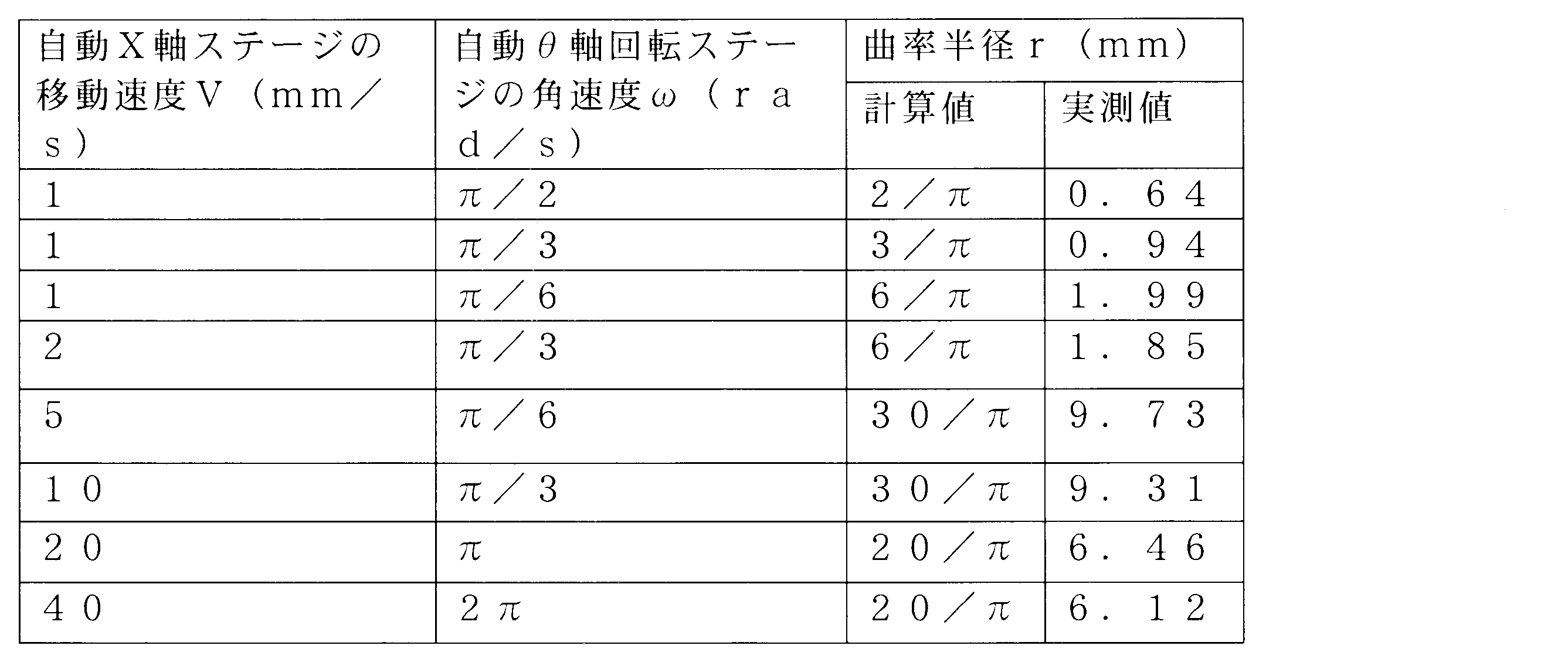
また、非接触で光ファイバを加熱しているので、屈曲部分を顕微鏡で拡大してもクラックはほとんど見つからなかった。
なお、実施例2では実施例1よりも曲率半径を幅広く調節できた。
また、実施例2では実施例1よりも高速で光ファイバを屈曲させることができ、生産性を高くすることも可能であった。
実施例1の構成で、自動X軸ステージを駆動せずに、アーク放電のみで光ファイバを加熱した。
その結果、約0.2mmの曲率半径で曲げることができたが、それ以外の曲率半径に成形することはできなかった。
Claims (19)
- 移動手段および非接触加熱手段を用いて光伝送媒体を屈曲させる光伝送媒体成形方法であって、
移動手段により光伝送媒体または非接触加熱手段を移動させながら、該非接触加熱手段により該光伝送媒体の一部を加熱する移動加熱工程と、
該光伝送媒体を曲げる屈曲工程と、
を有することを特徴とする光伝送媒体成形方法。 - 前記屈曲工程は、角速度を調節できる回転治具を用いて光伝送媒体を曲げることを特徴とする請求項1記載の光伝送媒体成形方法。
- 前記回転冶具は、前記非接触加熱手段近傍を中心として回転することを特徴とする請求項2記載の光伝送媒体成形方法。
- 前記屈曲工程は、光伝送媒体を90°曲げることを特徴とする請求項1記載の光伝送媒体成形方法。
- 前記屈曲工程は、光伝送媒体の自重により該光伝送媒体を曲げることを特徴とする請求項1記載の光伝送媒体成形方法。
- 前記非接触加熱手段はアーク放電電極であることを特徴とする請求項1記載の光伝送媒体成形方法。
- 前記移動手段は、一定速度で光伝送媒体または非接触加熱手段を移動させることを特徴とする請求項1記載の光伝送媒体成形方法。
- 前記光伝送媒体は、ガラス製光ファイバであることを特徴とする請求項1記載の光伝送媒体成形方法。
- 前記光伝送媒体は、複数本の光ファイバで構成される光ファイバ構造体であることを特徴とする請求項1記載の光伝送媒体成形方法。
- 前記光伝送媒体の複数箇所を順に屈曲させることを特徴とする請求項1記載の光伝送媒体成形方法。
- 光伝送媒体の一部を加熱する非接触加熱手段と、
該光伝送媒体または該非接触加熱手段を移動させる移動手段とを備え、
該非接触加熱手段と該移動手段は連動して、光伝送媒体または非接触加熱手段を移動させながら、該光伝送媒体の一部を加熱することを特徴とする光伝送媒体成形装置。 - さらに、角速度を調節して光伝送媒体を曲げる回転治具を備えることを特徴とする請求項11記載の光伝送媒体成形装置。
- 前記回転冶具は、前記非接触加熱手段近傍を中心として回転することを特徴とする請求項12記載の光伝送媒体成形装置。
- 前記非接触加熱手段はアーク放電電極であることを特徴とする請求項11記載の光伝送媒体成形装置。
- 前記移動手段は、一定速度で光伝送媒体または非接触加熱手段を移動させることを特徴とする請求項11記載の光伝送媒体成形装置。
- 前記移動手段は、二次元または三次元駆動ステージであることを特徴とする請求項11記載の光伝送媒体成形装置。
- さらに、光伝送媒体と非接触加熱手段との高さを調節する高さ調節手段を備えることを特徴とする請求項11記載の光伝送媒体成形装置。
- さらに、該非接触加熱手段および該移動手段の動作を制御する制御手段を備え、
該制御手段は、前記非接触加熱手段および移動手段を連動させて、光伝送媒体または非接触加熱手段を移動させながら、該光伝送媒体の一部を加熱することを特徴とする請求項11記載の光伝送媒体成形装置。 - 移動手段および非接触加熱手段を用いて屈曲した光伝送媒体を製造する光伝送媒体製造方法であって、
移動手段により光伝送媒体または非接触加熱手段を移動させながら、該非接触加熱手段により該光伝送媒体の一部を加熱する移動加熱工程と、
該光伝送媒体を曲げる屈曲工程と、
を有することを特徴とする光伝送媒体製造方法。
Priority Applications (4)
| Application Number | Priority Date | Filing Date | Title |
|---|---|---|---|
| CN2009801410299A CN102187255B (zh) | 2008-10-17 | 2009-10-16 | 光传输介质成形方法、光传输介质成形装置及光传输介质制造方法 |
| KR1020117010226A KR101327703B1 (ko) | 2008-10-17 | 2009-10-16 | 광전송매체 성형방법, 광전송매체 성형장치 및 광전송매체 제조방법 |
| JP2010533835A JP5226797B2 (ja) | 2008-10-17 | 2009-10-16 | 光伝送媒体成形方法、光伝送媒体成形装置及び光伝送媒体製造方法 |
| US13/124,630 US20110198765A1 (en) | 2008-10-17 | 2009-10-16 | Optical transmission medium shaping method, optical transmission medium shaping apparatus, and optical transmission medium manufacturing method |
Applications Claiming Priority (4)
| Application Number | Priority Date | Filing Date | Title |
|---|---|---|---|
| JP2008268945 | 2008-10-17 | ||
| JP2008-268945 | 2008-10-17 | ||
| JP2008-330897 | 2008-12-25 | ||
| JP2008330897 | 2008-12-25 |
Publications (1)
| Publication Number | Publication Date |
|---|---|
| WO2010044273A1 true WO2010044273A1 (ja) | 2010-04-22 |
Family
ID=42106443
Family Applications (1)
| Application Number | Title | Priority Date | Filing Date |
|---|---|---|---|
| PCT/JP2009/005414 Ceased WO2010044273A1 (ja) | 2008-10-17 | 2009-10-16 | 光伝送媒体成形方法、光伝送媒体成形装置及び光伝送媒体製造方法 |
Country Status (6)
| Country | Link |
|---|---|
| US (1) | US20110198765A1 (ja) |
| JP (1) | JP5226797B2 (ja) |
| KR (1) | KR101327703B1 (ja) |
| CN (1) | CN102187255B (ja) |
| TW (1) | TWI485447B (ja) |
| WO (1) | WO2010044273A1 (ja) |
Cited By (9)
| Publication number | Priority date | Publication date | Assignee | Title |
|---|---|---|---|---|
| WO2012029157A1 (ja) * | 2010-09-02 | 2012-03-08 | 株式会社巴川製紙所 | 屈曲光伝送媒体製造装置および屈曲光伝送媒体製造方法 |
| WO2012086585A1 (ja) | 2010-12-20 | 2012-06-28 | 株式会社 巴川製紙所 | 光伝送媒体曲げ加工装置および光伝送媒体曲げ加工方法 |
| WO2015076105A1 (ja) * | 2013-11-25 | 2015-05-28 | 住友電気工業株式会社 | 屈曲光ファイバの製造方法 |
| JP2016177073A (ja) * | 2015-03-19 | 2016-10-06 | 住友電気工業株式会社 | 光接続部品製造方法、光モジュール、および光接続部品 |
| WO2018042867A1 (ja) * | 2016-08-30 | 2018-03-08 | 住友電気工業株式会社 | 屈曲光ファイバの製造方法 |
| JP2018087988A (ja) * | 2017-12-28 | 2018-06-07 | 住友電気工業株式会社 | 屈曲光ファイバの製造方法 |
| US10436965B2 (en) | 2017-09-06 | 2019-10-08 | Sumitomo Electric Industries, Ltd. | Apparatus and method for manufacturing optical fiber having bent portion |
| US10539746B2 (en) | 2015-08-04 | 2020-01-21 | Sumitomo Electric Industries, Ltd. | Optical connection component |
| US10605993B2 (en) | 2015-08-13 | 2020-03-31 | Sumitomo Electric Industries, Ltd. | Optical connection component |
Families Citing this family (3)
| Publication number | Priority date | Publication date | Assignee | Title |
|---|---|---|---|---|
| JP6417710B2 (ja) | 2014-05-20 | 2018-11-07 | 住友電気工業株式会社 | 屈曲光ファイバ製造方法 |
| WO2018011991A1 (ja) * | 2016-07-15 | 2018-01-18 | 住友電気工業株式会社 | 光接続部品の製造方法 |
| CN110407454B (zh) * | 2019-07-04 | 2021-08-17 | 苏州安捷讯光电科技股份有限公司 | 一种热弯光纤加工平台的加工方法 |
Citations (4)
| Publication number | Priority date | Publication date | Assignee | Title |
|---|---|---|---|---|
| JPH09197155A (ja) * | 1996-01-18 | 1997-07-31 | Fujikura Ltd | 光ファイバの出射端の構造 |
| JP2002350668A (ja) * | 2001-05-22 | 2002-12-04 | Sumitomo Electric Ind Ltd | 光ファイバ融着接続方法 |
| JP2004325622A (ja) * | 2003-04-23 | 2004-11-18 | Fujikura Ltd | 光ファイバ部品 |
| JP2008532078A (ja) * | 2005-03-04 | 2008-08-14 | アイティーエフ ラボラトリーズ インク | 全ファイバー製の位相制御された遅延干渉計およびその製造方法 |
Family Cites Families (9)
| Publication number | Priority date | Publication date | Assignee | Title |
|---|---|---|---|---|
| US4073859A (en) * | 1975-02-10 | 1978-02-14 | Siemens Aktiengesellschaft | Technique for making silicon U-shaped members |
| JPH049004U (ja) * | 1990-05-11 | 1992-01-27 | ||
| DE19607069A1 (de) * | 1996-02-24 | 1997-08-28 | Braun Ag | Verfahren und Vorrichtung zum Biegen eines Bauteils aus einem thermoplastischen Kunststoff und Bauteil selbst |
| KR20010025532A (ko) * | 2001-01-03 | 2001-04-06 | 김기웅 | 광섬유 장식구조의 광섬유 벤딩방법 및 장치 |
| AU782604B2 (en) * | 2001-05-22 | 2005-08-11 | Sumitomo Electric Industries, Ltd. | Method for fusion splicing optical fibers and apparatus for heating spliced part by arc |
| US6935137B2 (en) * | 2001-10-09 | 2005-08-30 | General Electric Company | Method of and apparatus for forming discharge tubes of low-pressure discharge lamps |
| JP2005292718A (ja) * | 2004-04-05 | 2005-10-20 | Furukawa Electric Co Ltd:The | 光導波路、光導波路モジュールおよび光導波路の作成方法 |
| US7288996B2 (en) * | 2005-07-21 | 2007-10-30 | Intel Corporation | Apparatus and method reducing non-linearity in an output signal of an amplifier device |
| JP5224317B2 (ja) * | 2006-11-20 | 2013-07-03 | 古河電気工業株式会社 | 光導波路部品および光導波路部品の製造方法 |
-
2009
- 2009-10-16 CN CN2009801410299A patent/CN102187255B/zh active Active
- 2009-10-16 US US13/124,630 patent/US20110198765A1/en not_active Abandoned
- 2009-10-16 TW TW098135023A patent/TWI485447B/zh not_active IP Right Cessation
- 2009-10-16 KR KR1020117010226A patent/KR101327703B1/ko not_active Expired - Fee Related
- 2009-10-16 JP JP2010533835A patent/JP5226797B2/ja not_active Expired - Fee Related
- 2009-10-16 WO PCT/JP2009/005414 patent/WO2010044273A1/ja not_active Ceased
Patent Citations (4)
| Publication number | Priority date | Publication date | Assignee | Title |
|---|---|---|---|---|
| JPH09197155A (ja) * | 1996-01-18 | 1997-07-31 | Fujikura Ltd | 光ファイバの出射端の構造 |
| JP2002350668A (ja) * | 2001-05-22 | 2002-12-04 | Sumitomo Electric Ind Ltd | 光ファイバ融着接続方法 |
| JP2004325622A (ja) * | 2003-04-23 | 2004-11-18 | Fujikura Ltd | 光ファイバ部品 |
| JP2008532078A (ja) * | 2005-03-04 | 2008-08-14 | アイティーエフ ラボラトリーズ インク | 全ファイバー製の位相制御された遅延干渉計およびその製造方法 |
Cited By (16)
| Publication number | Priority date | Publication date | Assignee | Title |
|---|---|---|---|---|
| WO2012029157A1 (ja) * | 2010-09-02 | 2012-03-08 | 株式会社巴川製紙所 | 屈曲光伝送媒体製造装置および屈曲光伝送媒体製造方法 |
| CN103261930B (zh) * | 2010-12-20 | 2016-11-23 | 株式会社巴川制纸所 | 光传输介质弯曲加工装置及光传输介质弯曲加工方法 |
| WO2012086585A1 (ja) | 2010-12-20 | 2012-06-28 | 株式会社 巴川製紙所 | 光伝送媒体曲げ加工装置および光伝送媒体曲げ加工方法 |
| CN103261930A (zh) * | 2010-12-20 | 2013-08-21 | 株式会社巴川制纸所 | 光传输介质弯曲加工装置及光传输介质弯曲加工方法 |
| EP2657731A4 (en) * | 2010-12-20 | 2018-01-24 | Tomoegawa Co., Ltd. | Optical transmission medium bend working device and optical transmission medium bend working method |
| US9256017B2 (en) | 2010-12-20 | 2016-02-09 | Tomoegawa Co., Ltd. | Optical transmission medium bend working device and optical transmission medium bend working method |
| JP2015102663A (ja) * | 2013-11-25 | 2015-06-04 | 住友電気工業株式会社 | 屈曲光ファイバの製造方法 |
| WO2015076105A1 (ja) * | 2013-11-25 | 2015-05-28 | 住友電気工業株式会社 | 屈曲光ファイバの製造方法 |
| JP2016177073A (ja) * | 2015-03-19 | 2016-10-06 | 住友電気工業株式会社 | 光接続部品製造方法、光モジュール、および光接続部品 |
| US10539746B2 (en) | 2015-08-04 | 2020-01-21 | Sumitomo Electric Industries, Ltd. | Optical connection component |
| US10823917B2 (en) | 2015-08-04 | 2020-11-03 | Sumitomo Electric Industries, Ltd. | Optical connection component |
| US10605993B2 (en) | 2015-08-13 | 2020-03-31 | Sumitomo Electric Industries, Ltd. | Optical connection component |
| WO2018042867A1 (ja) * | 2016-08-30 | 2018-03-08 | 住友電気工業株式会社 | 屈曲光ファイバの製造方法 |
| US10836672B2 (en) | 2016-08-30 | 2020-11-17 | Sumitomo Electric Industries, Ltd. | Method for manufacturing bent optical fiber |
| US10436965B2 (en) | 2017-09-06 | 2019-10-08 | Sumitomo Electric Industries, Ltd. | Apparatus and method for manufacturing optical fiber having bent portion |
| JP2018087988A (ja) * | 2017-12-28 | 2018-06-07 | 住友電気工業株式会社 | 屈曲光ファイバの製造方法 |
Also Published As
| Publication number | Publication date |
|---|---|
| JPWO2010044273A1 (ja) | 2012-03-15 |
| JP5226797B2 (ja) | 2013-07-03 |
| US20110198765A1 (en) | 2011-08-18 |
| KR20110070996A (ko) | 2011-06-27 |
| CN102187255B (zh) | 2013-06-12 |
| TW201022747A (en) | 2010-06-16 |
| KR101327703B1 (ko) | 2013-11-11 |
| TWI485447B (zh) | 2015-05-21 |
| CN102187255A (zh) | 2011-09-14 |
Similar Documents
| Publication | Publication Date | Title |
|---|---|---|
| JP5226797B2 (ja) | 光伝送媒体成形方法、光伝送媒体成形装置及び光伝送媒体製造方法 | |
| JP5506322B2 (ja) | 光伝送媒体成形装置、光伝送媒体成形方法、および光伝送媒体製造方法 | |
| CN112118926B (zh) | 基于可变光束几何形状的激光的粉末床熔合 | |
| JP5346912B2 (ja) | 光伝送媒体曲げ加工装置および光伝送媒体曲げ加工方法 | |
| CN104843981A (zh) | 玻璃热弯成型过程中的加热自动控制方法 | |
| CN110587143A (zh) | 一种曲面fss激光刻蚀设备及方法 | |
| JP2019045794A (ja) | 屈曲部を有する光ファイバの製造装置および製造方法 | |
| WO2012029157A1 (ja) | 屈曲光伝送媒体製造装置および屈曲光伝送媒体製造方法 | |
| CN108351466A (zh) | 弯曲光纤的制造方法 | |
| JP2010262144A (ja) | 屈曲光伝送媒体製造装置および屈曲光伝送媒体製造方法 | |
| US20110052121A1 (en) | Fiber ball lens apparatus and method | |
| JP5253946B2 (ja) | 光伝送媒体成形方法および光伝送媒体成形装置 | |
| JP2013003455A (ja) | スポットサイズ変換導波路、及びその製造方法 | |
| TW201211599A (en) | Production apparatus for bent optical transmission medium and production method for bent optical transmission medium | |
| JP3151386B2 (ja) | 光ファイバ母材の製造方法 | |
| CN114829999A (zh) | 制造光纤传感器探针的设备及其制造方法 | |
| CN203947025U (zh) | 玻璃母材的延伸装置 | |
| JPH1149528A (ja) | ガラス素子の成形方法 | |
| JP2005520776A (ja) | 光繊維母材製造装置及びこれを用いた光繊維母材製造方法 | |
| KR20240076741A (ko) | 이중 열원을 이용하여 유리를 성형하는 방법 및 장치, 이를 이용하여 제조된 커브드 글라스 및 이를 포함하는 디스플레이 장치 | |
| JP2009023868A (ja) | 光学素子の成形方法 | |
| KR20220146121A (ko) | 굴곡부를 갖는 유리 기판의 제조 장치 및 제조 방법, 및 굴곡부를 갖는 유리 기판 | |
| JP2008150266A (ja) | 光学素子の成形方法 | |
| JP2005156657A (ja) | 光ファイバアレイの製造方法、及びその製造装置 | |
| JP2005068004A (ja) | ロッドキャップを含む軸蒸着装置 |
Legal Events
| Date | Code | Title | Description |
|---|---|---|---|
| WWE | Wipo information: entry into national phase |
Ref document number: 200980141029.9 Country of ref document: CN |
|
| 121 | Ep: the epo has been informed by wipo that ep was designated in this application |
Ref document number: 09820451 Country of ref document: EP Kind code of ref document: A1 |
|
| WWE | Wipo information: entry into national phase |
Ref document number: 2010533835 Country of ref document: JP |
|
| WWE | Wipo information: entry into national phase |
Ref document number: 13124630 Country of ref document: US |
|
| NENP | Non-entry into the national phase |
Ref country code: DE |
|
| ENP | Entry into the national phase |
Ref document number: 20117010226 Country of ref document: KR Kind code of ref document: A |
|
| 122 | Ep: pct application non-entry in european phase |
Ref document number: 09820451 Country of ref document: EP Kind code of ref document: A1 |