WO2010035432A1 - 画像形成装置および画像形成方法 - Google Patents
画像形成装置および画像形成方法 Download PDFInfo
- Publication number
- WO2010035432A1 WO2010035432A1 PCT/JP2009/004638 JP2009004638W WO2010035432A1 WO 2010035432 A1 WO2010035432 A1 WO 2010035432A1 JP 2009004638 W JP2009004638 W JP 2009004638W WO 2010035432 A1 WO2010035432 A1 WO 2010035432A1
- Authority
- WO
- WIPO (PCT)
- Prior art keywords
- toner
- image
- amount
- image forming
- developing
- Prior art date
- Legal status (The legal status is an assumption and is not a legal conclusion. Google has not performed a legal analysis and makes no representation as to the accuracy of the status listed.)
- Ceased
Links
Images


Classifications
-
- G—PHYSICS
- G03—PHOTOGRAPHY; CINEMATOGRAPHY; ANALOGOUS TECHNIQUES USING WAVES OTHER THAN OPTICAL WAVES; ELECTROGRAPHY; HOLOGRAPHY
- G03G—ELECTROGRAPHY; ELECTROPHOTOGRAPHY; MAGNETOGRAPHY
- G03G15/00—Apparatus for electrographic processes using a charge pattern
- G03G15/06—Apparatus for electrographic processes using a charge pattern for developing
- G03G15/08—Apparatus for electrographic processes using a charge pattern for developing using a solid developer, e.g. powder developer
-
- G—PHYSICS
- G03—PHOTOGRAPHY; CINEMATOGRAPHY; ANALOGOUS TECHNIQUES USING WAVES OTHER THAN OPTICAL WAVES; ELECTROGRAPHY; HOLOGRAPHY
- G03G—ELECTROGRAPHY; ELECTROPHOTOGRAPHY; MAGNETOGRAPHY
- G03G15/00—Apparatus for electrographic processes using a charge pattern
- G03G15/02—Apparatus for electrographic processes using a charge pattern for laying down a uniform charge, e.g. for sensitising; Corona discharge devices
- G03G15/0266—Arrangements for controlling the amount of charge
-
- G—PHYSICS
- G03—PHOTOGRAPHY; CINEMATOGRAPHY; ANALOGOUS TECHNIQUES USING WAVES OTHER THAN OPTICAL WAVES; ELECTROGRAPHY; HOLOGRAPHY
- G03G—ELECTROGRAPHY; ELECTROPHOTOGRAPHY; MAGNETOGRAPHY
- G03G15/00—Apparatus for electrographic processes using a charge pattern
- G03G15/06—Apparatus for electrographic processes using a charge pattern for developing
- G03G15/08—Apparatus for electrographic processes using a charge pattern for developing using a solid developer, e.g. powder developer
- G03G15/0822—Arrangements for preparing, mixing, supplying or dispensing developer
- G03G15/0848—Arrangements for testing or measuring developer properties or quality, e.g. charge, size, flowability
- G03G15/0849—Detection or control means for the developer concentration
-
- G—PHYSICS
- G03—PHOTOGRAPHY; CINEMATOGRAPHY; ANALOGOUS TECHNIQUES USING WAVES OTHER THAN OPTICAL WAVES; ELECTROGRAPHY; HOLOGRAPHY
- G03G—ELECTROGRAPHY; ELECTROPHOTOGRAPHY; MAGNETOGRAPHY
- G03G15/00—Apparatus for electrographic processes using a charge pattern
- G03G15/06—Apparatus for electrographic processes using a charge pattern for developing
- G03G15/08—Apparatus for electrographic processes using a charge pattern for developing using a solid developer, e.g. powder developer
- G03G15/0822—Arrangements for preparing, mixing, supplying or dispensing developer
- G03G15/0887—Arrangements for conveying and conditioning developer in the developing unit, e.g. agitating, removing impurities or humidity
- G03G15/0889—Arrangements for conveying and conditioning developer in the developing unit, e.g. agitating, removing impurities or humidity for agitation or stirring
-
- G—PHYSICS
- G03—PHOTOGRAPHY; CINEMATOGRAPHY; ANALOGOUS TECHNIQUES USING WAVES OTHER THAN OPTICAL WAVES; ELECTROGRAPHY; HOLOGRAPHY
- G03G—ELECTROGRAPHY; ELECTROPHOTOGRAPHY; MAGNETOGRAPHY
- G03G15/00—Apparatus for electrographic processes using a charge pattern
- G03G15/14—Apparatus for electrographic processes using a charge pattern for transferring a pattern to a second base
-
- G—PHYSICS
- G03—PHOTOGRAPHY; CINEMATOGRAPHY; ANALOGOUS TECHNIQUES USING WAVES OTHER THAN OPTICAL WAVES; ELECTROGRAPHY; HOLOGRAPHY
- G03G—ELECTROGRAPHY; ELECTROPHOTOGRAPHY; MAGNETOGRAPHY
- G03G15/00—Apparatus for electrographic processes using a charge pattern
- G03G15/50—Machine control of apparatus for electrographic processes using a charge pattern, e.g. regulating differents parts of the machine, multimode copiers, microprocessor control
- G03G15/5033—Machine control of apparatus for electrographic processes using a charge pattern, e.g. regulating differents parts of the machine, multimode copiers, microprocessor control by measuring the photoconductor characteristics, e.g. temperature, or the characteristics of an image on the photoconductor
- G03G15/5041—Detecting a toner image, e.g. density, toner coverage, using a test patch
-
- G—PHYSICS
- G03—PHOTOGRAPHY; CINEMATOGRAPHY; ANALOGOUS TECHNIQUES USING WAVES OTHER THAN OPTICAL WAVES; ELECTROGRAPHY; HOLOGRAPHY
- G03G—ELECTROGRAPHY; ELECTROPHOTOGRAPHY; MAGNETOGRAPHY
- G03G15/00—Apparatus for electrographic processes using a charge pattern
- G03G15/55—Self-diagnostics; Malfunction or lifetime display
- G03G15/553—Monitoring or warning means for exhaustion or lifetime end of consumables, e.g. indication of insufficient copy sheet quantity for a job
- G03G15/556—Monitoring or warning means for exhaustion or lifetime end of consumables, e.g. indication of insufficient copy sheet quantity for a job for toner consumption, e.g. pixel counting, toner coverage detection or toner density measurement
-
- G—PHYSICS
- G03—PHOTOGRAPHY; CINEMATOGRAPHY; ANALOGOUS TECHNIQUES USING WAVES OTHER THAN OPTICAL WAVES; ELECTROGRAPHY; HOLOGRAPHY
- G03G—ELECTROGRAPHY; ELECTROPHOTOGRAPHY; MAGNETOGRAPHY
- G03G21/00—Arrangements not provided for by groups G03G13/00 - G03G19/00, e.g. cleaning, elimination of residual charge
- G03G21/14—Electronic sequencing control
Definitions
- the present invention relates to a technique for forming an image using an electrophotographic method.
- a two-component developer mainly composed of toner particles and carrier particles is used in a developing device included in an electrophotographic or electrostatic recording image forming apparatus.
- a developing device included in an electrophotographic or electrostatic recording image forming apparatus.
- many developing devices use a two-component developer.
- the toner concentration of the two-component developer that is, the ratio of the toner particle weight to the total weight of the carrier particles and toner particles
- the toner concentration of the two-component developer is an extremely important factor in stabilizing the image quality.
- the toner particles of the two-component developer are consumed during development, and the toner concentration changes.
- the toner concentration of the two-component developer in the developing device is detected, and toner replenishment to the developing device is controlled according to the detected toner concentration, so that the toner concentration of the two-component developer is controlled to be constant.
- Patent Document 1 A technique (Patent Document 1) is disclosed.
- the main factor is a change in the charge amount of the toner.
- the toner charge amount is an important factor in stabilizing the image quality. Since the electrophotographic method and the electrostatic recording method form an image using electrostatic force, the density of the image fluctuates when the charge amount of the toner fluctuates.
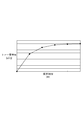
- FIG. 10 is a graph showing an example of change in the toner charge amount by stirring.
- the charge amount of the toner left for a long time is agitated in the developing unit and rubs against the carrier to be frictionally charged.
- An example of a change in the toner charge amount according to the toner consumption amount when a certain 20 originals are printed will be described with reference to FIGS. 11A to 11C.
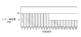
- FIG. 11A is a graph showing the toner consumption for each printing in the example described in FIGS. 11A to 11C.
- the amount of toner consumed for printing the 1st to 10th sheets is 2T (mg), and the amount of toner consumed for printing the 10th to 20th sheets is T (mg). ).
- FIG. 11B is a graph showing the amount of toner replenished for each sheet. The amount of toner consumed for development is replenished.
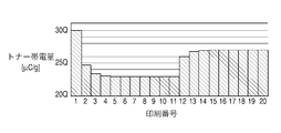
- FIG. 11C is a graph showing the toner charge amount at the start of printing for each sheet in the situation shown in FIGS. 11A and 11B.
- the toner is sufficiently agitated before the print job is input, and the toner charge amount is 30Q ( ⁇ C / g).
- new toner that is not sufficiently frictionally charged is replenished in the developing device, so that frictional charging due to stirring in the developing device is not in time, and the toner charge amount gradually decreases.
- the toner charge amount converges around 23Q ( ⁇ C / g).
- the balance between the replenished toner and the toner remaining in the developing device changes, so the toner charge amount gradually increases to 27Q ( ⁇ C / g). Converge around.
- the toner charge amount may vary for each image to be output. Since the density of the image also fluctuates in accordance with the fluctuation of the toner charge amount, it may be impossible to output a document with a desired density.
- a method for solving this there is a method of detecting the density of the developed image and supplying toner if the density is lower than a desired value. Also, there is a method of correcting density gradation of an image signal instead of toner replenishment control (Patent Document 2).
- JP-A-5-303280 JP 2000-238341 A Japanese Patent Laid-Open No. 06-130768
- both the above-described method for detecting the density of the developed image and the method of Patent Document 2 need to detect the density after creating a patch for density detection. There was a problem that the performance was lowered.
- the present invention has been made in view of the above problems, and an object thereof is to provide a technique for obtaining a stable output image at all times in image formation using toner.
- the image forming apparatus of the present invention comprises the following arrangement. That is, an image processing unit that performs image processing on an image signal using an image processing condition, and an image that forms an image by electrophotography using a controlled process condition based on the image processed image signal
- An image forming apparatus including a forming unit, a supply unit configured to supply toner to the developing unit based on an instructed toner supply amount; The developing means for developing the latent image, the toner consumption amount predicting means for predicting the toner consumption amount for outputting the image from the image data indicating the image, and the toner replenishment amount determined from the image signal indicating the image.
- a toner replenishment amount determination unit an acquisition unit that acquires a time for stirring the toner in the developing unit; the predicted toner consumption amount; the toner replenishment amount; Use between, guess toner charge amount, and having a control means for controlling at least one of the image processing condition and the process condition.
- the image forming method of the present invention comprises the following arrangement. That is, an image processing unit that performs image processing on an image signal using image processing conditions, and an output image is formed by electrophotography using controlled process conditions based on the image processed image signal.
- a toner replenishment amount determination step for determining the toner replenishment amount, an acquisition step for acquiring a toner agitation time in the developing unit, the predicted toner consumption amount, and the toner replenishment step And using the time during which the stirring, guess toner charge amount, and having a control step of controlling at least one of the image processing condition and the process condition.
- a stable output image can always be obtained in image formation using toner.
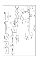
- FIG. 1 is a block diagram illustrating a configuration example of a digital multifunction peripheral according to a first embodiment.
- FIG. 3 is a flowchart illustrating processing performed by the digital multifunction peripheral according to the first embodiment.
- FIG. 4 is a diagram illustrating an example of a photosensitive drum 114 on which an output image and a patch image are formed.
- FIG. 4 is a block diagram illustrating a configuration of an image forming apparatus according to a second embodiment. The figure explaining a gradation characteristic and correction
- FIG. 4 is a diagram for explaining operation timing of the image forming apparatus.
- FIG. 4 is a diagram for explaining operation timing of the image forming apparatus.
- FIG. 4 is a diagram for explaining operation timing of the image forming apparatus.
- FIG. 4 is a diagram for explaining operation timing of the image forming apparatus.
- 11A and 11B are graphs showing toner charge amounts at the start of printing for each sheet in the situation shown in FIGS.
- FIG. 3 is a schematic diagram illustrating a configuration example of an image forming apparatus in which image forming stations are sequentially arranged.
- FIG. 9 is a block diagram illustrating a configuration of an image forming apparatus according to a third embodiment.
- FIG. 9 is a block diagram illustrating a configuration of an image forming apparatus according to a third embodiment.
- Example 1 The image forming apparatus according to the present embodiment forms an electrostatic latent image on an image bearing member such as a photosensitive member or a dielectric member by an electrophotographic method or an electrostatic recording method, and supplies the developer to the electrostatic latent image.
- the image is developed by a developing apparatus accompanied by a visible image. Therefore, the present embodiment can be applied to any image forming apparatus having the same or equivalent configuration.
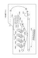
- FIG. 1 is a block diagram illustrating a configuration example of an electrophotographic digital multifunction peripheral as an example of an image forming apparatus according to the present exemplary embodiment.
- the document 101 is read as an image by the CCD 102 via an imaging lens (not shown).
- the CCD 102 decomposes the read image into a large number of pixels, and generates a photoelectric conversion signal (analog signal) corresponding to the density of each pixel.
- the generated analog image signal of each pixel is amplified to a predetermined level by the amplifier 103 and converted to, for example, an 8-bit (255 gradation) digital image signal by the analog / digital converter (A / D converter) 104.
- a / D converter analog / digital converter
- the digital image signal is supplied to a ⁇ converter (here, a converter configured with 256-byte data and performing density conversion by a lookup table method) 105, and the ⁇ converter 105 converts the digital image signal into the digital image signal.
- ⁇ correction is performed.
- the digital image signal subjected to ⁇ correction is input to a digital / analog converter (D / A converter) 106.
- the D / A converter 106 performs D / A conversion on the digital image signal and converts the digital image signal into an analog image signal.
- the D / A converter 106 outputs the converted analog image signal. This analog image signal is supplied to one input terminal of the comparator 107.
- the other input terminal of the comparator 107 receives a triangular wave signal with a predetermined period supplied from the triangular wave generation circuit 108, and the analog image signal is compared with the triangular wave signal and subjected to pulse width modulation.
- the binary image signal resulting from the pulse width modulation is input to the laser drive circuit 109, and the laser drive circuit 109 controls ON / OFF of light emission of the laser diode 110 based on the binary image signal. To do.
- Laser light emitted from the laser diode 110 is scanned in the main scanning direction by a well-known polygon mirror 111, passes through an f ⁇ lens 112 and a reflection mirror 113, and onto a photosensitive drum 114 which is an image carrier rotating in the direction of an arrow. Irradiated.
- the photosensitive drum 114 is uniformly charged by the exposure device 115 and then uniformly charged, for example, negatively by the primary charger 116. Thereafter, an electrostatic latent image is formed on the photosensitive drum 114 by irradiation with laser light.
- the electrostatic latent image is developed into a visible image (toner image) by the developing device 117.
- a DC bias component corresponding to an electrostatic latent image forming condition and an AC bias component for improving development efficiency are superimposed and applied to the developing device 117.
- This toner image is transferred to a transfer material 121 held on a belt-like transfer material carrier (transfer belt) 120 that is stretched between two rollers 118 and 119 and driven endlessly in the direction of the arrow in the drawing.
- the image is transferred by the action of the device 122.
- the transfer material 121 onto which the toner image has been transferred is conveyed to a fixing device 123, and the fixing device 123 fixes the toner image on the transfer material 121 to the transfer material 121. Then, the transfer material 121 on which the toner image is fixed is discharged.
- the residual toner remaining on the photosensitive drum 114 is then scraped off by the cleaner 124 and collected. Further, after the transfer material 121 is separated, the residual toner on the transfer belt 120 remains around the transfer belt 120, such as a blade installed downstream of the position where the transfer material 121 is delivered to the fixing device 123. It is scraped off by the cleaner 125.
- FIG. 1 only a single image forming station (including the photosensitive drum 114, the exposure device 115, the primary charger 116, the developing device 117, etc.) is shown for the sake of simplicity.
- image forming stations for cyan, magenta, yellow, and black are sequentially arranged on the transfer belt 120 in the moving direction.
- the developing devices 117 of the respective colors are arranged around the periphery of one photosensitive drum 114.
- yellow, magenta, cyan, and black developing devices 117 are arranged in a rotatable housing. That is, a desired developing device 117 is opposed to the photosensitive drum 114 to develop a desired color.
- a patch sensor 126 is provided on the surface of the photosensitive drum 114 at a position between the developing unit 117 and the facing portion of the transfer belt 120 in the rotation direction of the photosensitive drum 114.
- the patch sensor 126 detects the density of the density detection developed image (patch) developed on the photosensitive drum 114, controls the toner replenishment amount of the developing device 117, and the LUT (look-up table) included in the ⁇ converter 105. ). Details of toner replenishment control and gradation correction by LUT will be described later.
- the controller 900 controls each part constituting the digital multi-function peripheral.
- the controller 900 includes a CPU, a ROM that stores a control program, a RAM that temporarily stores programs and data, and the like.
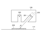
- the patch sensor 126 includes a light source 201 such as an LED, a density measuring light receiving element 202 that receives light emitted from the light source 201 and reflected by the patch image 200, and a light amount of the light source 201 to make the light amount of the light source 201 constant.
- a light amount adjusting light receiving element 203 that directly receives light is formed.
- step S301 the controller 900 generates a patch image. Then, the generated patch image is formed on the photosensitive drum 114 together with a print image (output image) based on image data acquired from the outside as an original print target.
- the controller 900 controls the patch sensor 126, and the patch sensor 126 reads the density value of the patch image on the photosensitive drum 114 as a measurement value.
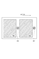
- FIG. 4 is a diagram illustrating an example of the surface of the photosensitive drum 114 on which a print image and a patch image are formed.
- the patch images 401 and 402 are formed in an area where a print image is not formed at an arbitrary timing and an arbitrary density level. Note that it is not always necessary to form a patch image when forming a print image.
- the patch image may be formed once for every 10 A4-size print images.
- the patch image formation frequency may be variable based on required accuracy.
- the density of the patch image may be a fixed value that is regarded as important or may be variable.
- the patch sensor 126 reads the density of the patch image formed on the photosensitive drum 114.
- the print image formed on the photosensitive drum 114 is transferred to the transfer material 121, and the patch image is not transferred to the transfer material 121 and is erased by the cleaner 125 after the density is detected by the patch sensor 126.
- the controller 900 detects or estimates a parameter.
- the parameters are toner density, toner charge amount, temperature / humidity in the image forming apparatus, carrier deterioration degree, and the like.
- the toner density can be detected by using a sensor of an optical reflection light quantity detection method or an inductance detection method.
- the temperature / humidity may be detected by a general method. Detection of the degree of deterioration of the carrier can be performed by using a count value of the number of printed sheets, a count value measured in advance and a LUT of the degree of deterioration.
- the toner density and the toner charge amount are described as being estimated, not measured by a sensor, and other necessary parameters are described as being detectable.
- Image data that is an object of image formation is stored in a memory (not shown) in the digital multi-function peripheral. Therefore, the controller 900 first refers to the pixel value of each pixel constituting the image data, and obtains an accumulated value (integrated value) of each pixel value. The amount of toner consumed for forming a print image of this image data is estimated from the obtained accumulated value. Further, the controller 900 acquires data indicating the amount of toner replenished to the developing device 117 from a toner replenishing device (hopper) (not shown).
- hopper toner replenishing device
- the controller 900 performs calculation processing based on the following formulas 1 and 2 using the toner consumption amount and the toner replenishment amount.
- the following calculation formula is a model called “observer”, which is similar to an observer in control engineering.
- Equation 1 is a state equation and Equation 2 is an output equation.
- u is a 1 ⁇ 2 matrix indicating the estimated toner consumption and the amount of toner replenishment acquired by the controller 900.
- x is a 1 ⁇ 2 matrix (state variable) indicating the toner density and the toner charge amount.
- y is an output patch density (output) at a certain input patch density level, and A, B, C, and D are a system matrix, a control matrix, an observation matrix, and a direct matrix that define the model, respectively.
- y obsv is the output patch density y in Equation 2
- y plant is the density value measured by the patch sensor 126
- L is the observer gain.
- the observer gain is a matrix for correcting the deviation of the state quantity in the model from the difference between y obsv and y plant .
- the observer can more reliably estimate the matrix x, that is, the toner density and the toner charge amount.
- step S303 the controller 900 performs processing for obtaining the matrix x at the next image formation. This is because the parameters in the digital multi-function peripheral fluctuate with time and affect the density of the image to be formed.
- a matrix x at a certain representative timing during the next image forming process is obtained.
- the controller 900 obtains a time t from the present time to the next image formation time.
- the controller 900 stores the image data of the next image formation target in the memory. Therefore, the controller 900 refers to the pixel value of each pixel constituting the image data, and accumulates (integrates) the respective pixel values. Value). Then, from the accumulated value obtained, the amount of toner consumed to print an image based on the image data is estimated.
- the controller 900 also determines the toner replenishment amount. Thereby, the matrix u indicating the determined toner supply amount and the determined toner consumption amount can be determined.
- the determined toner replenishment amount may be an arbitrary amount, but is assumed to be equal to the toner consumption amount for the sake of simplicity. That is, when the toner density is controlled to be constant, the model can predict the movement of the toner charge amount shown in FIGS. 11A to 11C, for example.
- the calculation process for obtaining the matrix x at the next image formation is performed again.
- the calculation result (matrix x) at the previous calculation is used as the initial value.
- the output patch density y at the next image formation is calculated from the obtained matrix x.
- step S304 the controller 900 corrects the LUT included in the ⁇ converter 105 based on the calculated output patch density y at the next image formation.
- the corrected LUT is used in ⁇ conversion for the next image data to be image formed.
- the density gradation characteristic can be compensated at all times.
- the density gradation characteristic is predicted and controlled, but may be used in combination with other general feedback control.
- the density measurement timing of the patch image is performed at an arbitrary timing.
- the measurement frequency may be changed according to the amount of deviation between the predicted value and the actual measurement value.
- the measured value is not limited to the density, but may be any value that can estimate the state quantity of the patch image, such as reflectance, toner weight, and toner charge amount.
- the parameter prediction timing is set to a typical timing during the next image forming process, but is not limited to this.
- a plurality of parameter prediction timings may be set, the results predicted at each timing may be averaged, and the average value may be used as the prediction value.
- toner is replenished arbitrarily.
- the toner replenishment amount is determined so that the difference between parameters obtained at each timing is minimized, and the density fluctuation during image output is minimized. It is also possible to make it.
- the toner density and the toner charge amount are estimated.
- these may be detected using a sensor or the like, and can be approximated by a state space model and an observer can be designed.
- other parameters may be estimated.
- An image forming apparatus includes an image processing unit that performs image processing on an image signal using an image processing condition, and an electrophotographic process that uses a controlled process condition based on the image signal subjected to the image processing.
- An image forming apparatus having an image forming unit that forms an output image by a method. More specifically, an electrostatic latent image is formed on an image carrier such as a photosensitive member or a dielectric by an electrophotographic method, an electrostatic recording method, or the like, and the gradation characteristics of the electrostatic latent image are corrected as appropriate.
- the electrostatic latent image is developed by a developing device accompanied by developer replenishment to form a visible image.
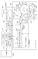
- FIG. 5 is a block diagram illustrating a configuration example of the image forming apparatus according to the present embodiment.
- the controller 1001 receives an image signal from the external device 1003 and issues a print command.
- the external device 1003 has an interface with a hard disk drive (not shown), a computer, a server, a network, etc., and outputs an image signal.
- the ⁇ conversion unit 1101 performs ⁇ conversion (first gradation correction) on the image signal from the external device 1003 using a look-up table (LUT).
- the ⁇ correction unit 1102 performs ⁇ correction (second gradation correction) on the image signal from the ⁇ conversion unit 1101 using the LUT.
- the HT processing unit 1103 performs halftone processing (HT processing) on the image signal subjected to gradation correction from the ⁇ correction unit 1102.
- the PWM processing unit 1104 compares the image signal that has been subjected to the halftone process with a triangular wave signal having a predetermined period, and outputs a pulse width modulated laser drive signal.
- This laser drive signal is output to the printer engine 1002.
- the laser diode 1201 emits laser light in response to a laser drive signal.
- the emitted laser light passes through a polygon mirror (not shown), an f ⁇ lens (not shown), and a reflection mirror 1202 and is irradiated onto a photosensitive drum 1203 that is an image carrier rotating in the direction of the arrow. As a result, an electrostatic latent image is formed on the photosensitive drum 1203.
- the photosensitive drum 1203 is uniformly charged by the exposure device 1204 and then uniformly charged by the charger 1205. Thereafter, an electrostatic latent image corresponding to the printed image is formed on the photosensitive drum 1203 in response to the previous laser beam irradiation.
- the electrostatic latent image is developed as a visible image (toner image) with toner supplied from a developing device (developing unit) 1206.
- the developing device 1206 includes a plurality of stirring screws 1401 and a developing sleeve 1402.
- a developer (carrier) and toner are stored.
- the agitating screw 1401 agitates the carrier and the toner by driving, and frictionally charges the toner.
- the developing sleeve 1402 rotates while adhering charged toner and a carrier to the surface, and supplies the toner to the electrostatic latent image on the photosensitive drum 1203.
- the developed toner image is transferred onto a belt-shaped transfer material carrier (transfer belt) 1207 that is stretched between a plurality of rollers and driven endlessly by the action of the primary transfer unit 1208.
- the toner image transferred to the transfer material carrier 1207 is transferred to the transfer material 1210 by the secondary transfer device 1209.
- the transfer material 1210 is conveyed, passes through the fixing device 1211, and fixes the toner image on the transfer material 1210. Then, the transfer material 1210 is discharged.
- the residual toner remaining on the photosensitive drum 1203 is then scraped off by the cleaner 1212 and collected. Further, after the transfer material 1210 is separated, the remaining toner on the transfer material carrier 1207 is scraped off by a cleaner 1213 such as a blade.
- FIG. 5 only a single image forming station (including the photosensitive drum 1203, the charging device 1205, the developing device 1206, etc.) is shown for the sake of simplicity.
- image forming stations for cyan, magenta, yellow, and black are sequentially arranged on the transfer material carrier 1207 along the moving direction thereof.
- each color developing device 1206 is arranged around one photosensitive drum 1203 along the periphery.
- yellow, magenta, cyan, and black developing devices 1206 are arranged in a rotatable housing. That is, a desired developing device 1206 is opposed to the photosensitive drum 1203 to develop a desired color.
- FIG. 12 is a diagram illustrating a configuration example of an image forming apparatus in which four image forming stations are sequentially arranged.
- the controller 1001 includes the following units.
- a color separation unit 1108 that separates the image signal into each color Signal processing units 1100a, 1100b, 1100c, 1100d for each color ( ⁇ conversion unit 1101, ⁇ correction unit 1102, HT processing unit 1103, PWM processing unit 1104, video count unit 1105, correction amount calculation unit 1106, patch data storage unit 1107 including)
- Each of the image forming stations 1200a, 1200b, 1200c, and 1200d is controlled by a corresponding signal processing unit.
- Each image forming station includes a laser diode 1201, a reflecting mirror 1202, a photosensitive drum 1203, an exposure device 1204, a charger 1205, a developing device 1206, a cleaner 1212, a replenisher 1217, and a toner tank 1218.
- a patch sensor 1214 (the same configuration as that of the first embodiment) is provided at a position between the developing device 1206 and the facing portion of the transfer material carrier 1207.
- the patch sensor 1214 detects the density of the density detection developed image (patch) developed on the photosensitive drum 1203, controls the toner supply to the developing device 1206, and the LUT (look-up table) included in the ⁇ converter 1101. Perform the correction. Details of tone correction by toner replenishment control and LUT correction will be described later.
- the video count unit 1105 integrates the image signals per page output from the HT processing unit 1103 and outputs the integrated value to the supply amount calculation unit 1215 as a video count value VC.
- the video count value VC is an integrated value of signal values n i, j (i and j are vertical and horizontal coordinates, respectively) of each pixel constituting an image for one page, and is calculated by Expression (4).
- the supply amount calculation unit 1215 predicts the toner amount T consumed by the image forming apparatus for printing one page from the video count value VC using Expression (5).
- T VC ⁇ k
- k is a coefficient representing the toner weight per unit signal value. Actually, the amount of toner consumed varies depending on temperature, humidity, the state of the developing device 1206, and the like. Therefore, the predicted toner amount is different from the actually consumed toner amount and includes an error.
- the replenishment amount correction unit 1216 adjusts the toner replenishment amount based on the patch density detected by the patch sensor 1214, and outputs a replenishment motor rotation signal corresponding to the adjusted toner replenishment amount.
- the replenishment motor rotation signal is a signal for rotationally driving the replenishment motor provided in the replenisher 1217, and the replenishment motor rotation speed N indicated by this signal can be calculated by Expression (6).
- T rem (n + 1) (T + k d ⁇ (D target ⁇ D) + T rem ) ⁇ N ⁇ T div
- ⁇ is a remainder calculation symbol
- T div is the toner replenishment amount per rotation of the replenishment motor of the replenisher 1217
- D is the patch density value measured by the patch sensor 1214.
- D target is a target patch density value
- k d is a coefficient for determining the replenishment adjustment amount
- T rem is the previous “toner replenishment amount per print sheet replenished from the toner tank 1218 to the developing device 1206. Represents the remainder when calculating “Th”.
- the amount of toner in the developing unit 1206 is always constant by supplying the same amount of toner as the amount of toner consumed by the replenisher 1217.
- the toner amount calculated by the replenishment amount calculation unit 1215 and the toner amount replenished by the replenisher 1217 include an error.
- the replenishment amount adjustment using the patch density is performed. This utilizes the correlation between the amount of toner remaining in the developing device 1206 and the density of the patch image to be developed. If the patch density measured by the patch sensor 1214 is lower than expected, the replenishment amount is increased because the toner amount in the developing device 1206 is likely to be decreased. Conversely, if the patch concentration is high, the replenishment amount is decreased. With the above adjustment, the toner amount in the developing device 1206 is kept constant. Further, since the replenisher 1217 can be driven only in units of one rotation, the amount of toner that could not be replenished is carried over to subsequent calculations.
- the replenisher 1217 rotates the replenishment motor by the replenishment motor rotation number N indicated by this signal in accordance with the replenishment motor rotation signal output from the replenishment amount correction unit 1216, and develops the toner stored in the toner tank 1218. Refill the vessel 1206. Thus, toner can be supplied based on the instructed toner supply amount.
- the reason why the drive unit of the replenisher 1217 is set to one rotation is that the replenishment amount is stabilized because the blade of the screw (so-called tooth portion) returns to the same place in one rotation, and the replenishment amount by the rotation phase is This is not the case when replenishment control considering other differences or other replenishment methods are used.
- the gradation conversion processing is performed in two steps by the ⁇ conversion unit 1101 and the ⁇ correction unit 1102.
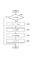
- a method for creating an LUT used by the ⁇ conversion unit 1101 will be described with reference to the flowchart of FIG. 7A.
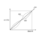
- the image forming apparatus has inherent gradation characteristics.
- the relationship between the image signal and its output density is For example, the characteristic 500 before ⁇ conversion in FIG. 6A is obtained.
- the gradation characteristic of the image forming apparatus is preferably linear with respect to the density or brightness of the output image with respect to the input signal. Therefore, the controller 1001 creates a ⁇ -LUT in order to obtain a desired gradation characteristic.
- the controller 1001 determines whether to create a ⁇ -LUT based on a preset condition (step S601). For example, when there is a possibility that the gradation characteristics may change significantly, such as immediately after the image forming apparatus is started up or after a certain number of prints, for example, 5000 prints, create a ⁇ -LUT. to decide. If it is determined that a ⁇ -LUT is to be created as a result of such determination, the process proceeds to step S602. On the other hand, if it is determined not to create a ⁇ -LUT, this process is terminated. In this embodiment, when it is determined to create a ⁇ -LUT, image output based on the print command is stopped, a multi-gradation patch is formed, and a ⁇ -LUT creation process is performed.
- the patch data storage unit 1107 outputs the multi-tone patch data to the HT processing unit 1103.
- the patch data is composed of 17-gradation patches (0, 16, 32... 255 in the case of 8 bits) in which intervals of input signal values are evenly arranged in order to calculate gradation characteristics.
- the size of each patch is a size that can be detected by the patch sensor 1214, for example, 1 cm square.
- the number of gradations of the patch and the number of patches are not particularly limited.
- a latent image of a multi-tone patch on the photosensitive drum 1203 is used. Is formed (step S603).
- the patch sensor 1214 measures the density of each patch on the photosensitive drum 1203 (step S604).
- the ⁇ conversion unit 1101 receives a patch density signal indicating the measured density of each patch measured in step S604 from the patch sensor 1214, creates a ⁇ -LUT from the gradation characteristics of the image forming apparatus based on the patch density signal, Store (step S605).
- the ⁇ -LUT calculates a characteristic (solid line) having a characteristic opposite to that before ⁇ conversion from the characteristic before ⁇ conversion (dotted line) obtained based on the density of each patch obtained in step S604. Created based on characteristics with opposite characteristics.
- FIG. 6A shows a schematic diagram of the relationship between the characteristic 500 before conversion, the ⁇ -LUT 502 having the opposite characteristic, and the ideal characteristic 501.
- the creation of the ⁇ -LUT performed by the ⁇ conversion unit 1101 requires time for performing a plurality of patch outputs and density measurements. For this reason, if the ⁇ -LUT creation process in the ⁇ correction unit 1101 is frequently performed in the ⁇ correction unit 1101 such as for each print, the productivity is significantly reduced. In addition, when the ⁇ -LUT is created, toner consumption and replenishment are involved, so strictly speaking, the gradation characteristics of the image forming apparatus are changed.
- the ⁇ correction unit 1102 predicts the gradation characteristics based on the input data, thereby correcting the gradation characteristics at a high frequency without requiring time for patch output or the like. That is, the basic gradation characteristics that have changed over a long period of time, such as deterioration of the image forming apparatus over time, are corrected by the ⁇ conversion unit 1101, and the gradation characteristics that have changed over a short period of time are corrected by the ⁇ correction unit 1102.
- the ⁇ correction unit 1102 is for compensating for fluctuations occurring in a short time, that is, fluctuations in the developing toner amount due to toner agitation, toner replenishment, toner consumption due to development, and the like. As described with reference to FIGS. 11A to 11C, such a variation due to the toner state occurs even in a short time such as when several sheets of print are output.
- the correction amount calculation unit 1106 calculates the correction amount and corrects the gradation characteristics.
- the ⁇ correction unit 1102 uses the process variation information of the engine in the (n ⁇ 1) th print from the predicted value of the toner charge amount at the start of the (n ⁇ 1) th print (n ⁇ 1).
- the toner charge amount at the end of printing of the first sheet (at the start of printing of the nth sheet) is predicted.
- the process variation information indicates variation information of toner consumption, replenishment motor rotation speed, and development motor rotation speed. Then, an output density is calculated based on the predicted toner charge amount, and a gradation conversion condition ( ⁇ -LUT) is created.
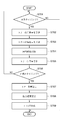
- step S701 determines whether to predict the toner charge amount based on a preset condition. The conditions for performing the prediction will be described later. If it is determined that the toner charge amount is not predicted as a result of the determination, the process is terminated. If it is determined that the toner charge amount is predicted, the process proceeds to step S702.
- the correction amount calculation unit 1106 When the correction amount calculation unit 1106 receives the video count value VC from the video count unit 1105, the correction amount calculation unit 1106 predicts the toner consumption amount T per print sheet consumed by the developing device 1206 (step S702).
- the toner consumption amount T is obtained by the equation (5), similarly to the replenishment amount calculation unit 1215.
- the correction amount calculation unit 1106 acquires the toner consumption amount T by acquiring the video count value VC from the video count unit 1105, but acquires the toner toner consumption amount T from the replenishment amount calculation unit 1215. It doesn't matter if you do.
- the correction amount calculation unit 1106 uses the replenishment motor rotation signal (replenishment motor rotation speed N) from the replenishment amount correction unit 1216 to calculate the toner replenishment amount Th per print to be replenished from the toner tank 1218 to the developing device 1206. Prediction is performed using equation (7) (step S703).
- the correction amount calculation unit 1106 receives the rotation time of the developing screw 1401 from the developing device 1206, and sets the stirring time ton (n ⁇ 1) (step S704).
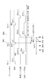
- steps S702, S703, and S704 details of the information acquired by the correction amount calculation unit 1106 in each of steps S702, S703, and S704 will be described with reference to a schematic diagram illustrating an order of each process illustrated in FIG.
- the top row of FIG. 8 shows the print command issue timing, and the image forming apparatus operates in response to the rise P (n) (n-th print command) of the issue timing signal.
- P (n) is issued from a control unit (not shown)
- the controller 1001 starts processing an image signal.
- the laser diode 1201 performs exposure processing based on the laser drive signal output from the controller 1001.
- the video count unit 1105 starts calculating the video count value, and the video count value of the nth print is determined at the time 801 when the exposure process ends.
- a developing motor rotation signal DEV (n) is output from a control unit (not shown) at a timing when the latent image formed on the photosensitive drum 1203 by the exposure process faces the developing device 1206.
- the developing device 1206 receives the developing motor rotation signal DEV (n), and drives the stirring screw 1401 and the developing sleeve 1402.
- the rotation time (stirring time t on ) of the developing screw 1401 is determined based on the rotation speed of the photosensitive drum 1203 and the nth image acquired when P (n) is issued by a stirring time determination function executed by a control unit (not shown). Determined from the size of
- the replenishment motor operates at the timing H (n) in time with the rising of the development motor rotation signal DEV (n) to replenish the developer 1206 with toner.
- the timing 802 before the n-th exposure processing rises is the timing when the processing in the ⁇ correction unit 1102 starts upon receiving P (n), and the ⁇ -LUT used for the tone conversion of the ⁇ correction unit 1102 is rewritten. It must be over.
- the information acquired in steps S702, S703, and S704 is information acquired before this.
- the video count value VC acquired in step S702 is determined at the falling timing 803 of the (n-1) th exposure timing E (n-1), that is, the (n-1) th video count value (ie, (N-1) Toner consumption in printing of the first sheet).
- the toner replenishment amount Th acquired in step S703 is the amount of toner replenished at the replenishment motor rotation timing H (n-1), and the replenishment motor rotation speed determined at the rising timing 804 of H (n-1). Calculation is performed using N (n-1).
- Agitation time t on the acquired in step S704 is the driving time of the developing motor rotation signal DEV (n-1), since the established immediately after the issuance of the time the print instruction P (n-1) Use this.
- the correction amount calculation unit 1106 uses the above information in the (n ⁇ 1) th print, and the toner charge amount at the end of the (n ⁇ 1) th print (when the nth print starts). Is predicted (step S705).
- the correction amount calculation unit 1106 calculates the average toner charge amount y in the developing device 1206 by the following equations (8) and (9).
- a state space model in control engineering is used in predicting the toner charge amount.
- the state space model is a mathematical model represented by a first-order simultaneous differential equation using inputs, outputs, and state variables.
- the fluctuation characteristic of the toner charge amount in the developing device 1206 is approximated by simultaneous differential equations, and the nth sheet is obtained using the state space model expressed by the equations (8) and (9).
- the toner charge amount y at the start of printing is estimated.
- u is a 1 ⁇ 2 matrix composed of a replenishing toner amount ⁇ Th / ton (n ⁇ 1) ⁇ per unit time and a consumed toner amount ⁇ T / ton (n ⁇ 1) ⁇ per unit time. is there.
- the matrix u can be calculated from the toner consumption amount T (n ⁇ 1), the toner replenishment amount Th (n ⁇ 1), and the stirring time ton (n ⁇ 1) calculated in steps S702, S703, and S704, respectively.
- X is a 1 ⁇ 2 matrix (state variable) indicating the toner density and the toner charge amount.
- A, B, C, and D are a system matrix, a control matrix, an observation matrix, and a direct matrix that define the model, respectively.
- the equations (8) and (9) are obtained by approximating the fluctuation characteristics of the toner charge amount in the developing device 1206 with simultaneous differential equations, and each matrix of A, B, C, D is uniquely determined by experiments or the like in advance. It is possible to use the value of. For example, the fluctuation of the toner charge amount when the toner consumption and the toner replenishment shown in FIGS.
- 11A to 11C are performed can be measured in advance by measuring the potential of the surface of the photosensitive drum 1203 and measuring the weight of the developed toner image.
- system identification in control engineering it is possible to obtain A, B, C, and D matrices from measurement data.
- Ton (n ⁇ 1) shown in FIG. 8 is the time for the toner charge amount to change due to toner consumption, replenishment, and stirring for the (n ⁇ 1) th print.
- the correction amount calculation unit 1106 obtains the change in the toner charge amount at the time t on (n ⁇ 1) by repeating Expression (8) and Expression (9) t on (n ⁇ 1) / ⁇ t times.
- ⁇ t is a unit time for calculation.
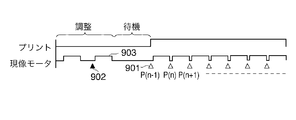
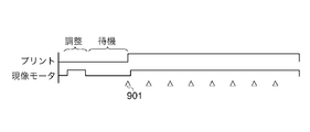
- FIG. 9A is a diagram illustrating a relationship between print processing performed by the image forming apparatus and driving of the developing motor.
- the development motor operates in accordance with the printing process, but also operates during adjustment of the image forming apparatus, for example, operation confirmation immediately after startup or creation of an LUT used by the ⁇ conversion unit 1101.
- the condition for predicting the toner charge amount is before driving the developing motor in FIG. 9A (timing 901 before the printing process and timing 902 before the developing motor is rotated by another process).
- the values of the state variable x and the toner charge amount y are updated by performing the processing of steps S702 to S705.
- the controller 1001 determines whether to create a ⁇ -LUT (S706).
- a ⁇ -LUT (S706).
- the controller 1001 determines whether to create a ⁇ -LUT (S706).
- processing is performed at timing 901 before print processing. That is, at the timing 901 before the printing process in FIG. 9A, the values of the state variable x and the toner charge amount y are updated in steps S702 to S705, and the ⁇ -LUT of the ⁇ correction unit 1102 is created in steps S707 to S709.
- the printing process is not performed, at the timing 902 when the developing motor rotates, only the processes of steps S702 to S705 are performed, and the values of the state variable x and the toner charge amount y are updated.
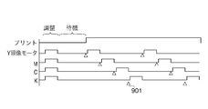
- the toner charge amount y at the time of creating a patch for rewriting the ⁇ -LUT of the ⁇ converter 1101 is stored as a reference toner charge amount y norm .
- the ⁇ -LUT of the ⁇ conversion unit 1101 is written by the predicted toner charge amount y norm at timing 902. Change. Thereby, ideal gradation characteristics can be obtained.
- this is set as the reference state, and in the processing of steps S707 to S709, the gradation characteristics are corrected based on the change in the toner charge amount from the reference state.
- the development motor is started and stopped once for each printed sheet.
- the developing motor continues to rotate for a plurality of prints as shown in FIG. 9B
- the toner charge amount at the start of each print can be predicted.
- a developing motor operates independently for each color. In this case, the toner charge amount prediction at the timing for each color is performed.
- the correction amount calculation unit 1106 uses the predicted toner charge amount y and the reference toner charge amount y norm to perform a calculation process according to Expression (14), so that the toner weight fluctuation amount per unit area is obtained. ⁇ M is obtained (step S707).
- the toner weight M represents the amount of toner developed when a predetermined electrostatic latent image is developed
- ky is a proportional constant indicating the relationship between the toner charge amount and the toner weight. This indicates that the toner weight M developed into a predetermined electrostatic latent image is inversely proportional to the toner charge amount y.
- the latent image is a latent image for forming the highest density portion formed with the maximum input signal value 255. Note that the toner weight of other density portions may be obtained.
- the correction amount calculation unit 1106 converts the toner weight fluctuation amount ⁇ M per unit area into an output density fluctuation ⁇ OD (step S708). Since the relationship between the toner weight M per unit area and the output density OD is uniquely determined when the same transfer material 1210 is used, the conversion in step S708 uses a LUT or a conversion formula created in advance. This can be done easily.
- the ⁇ correction unit 1102 receives the output density fluctuation ⁇ OD at the maximum value 255 of the input image signal from the correction amount calculation unit 1106, and creates a ⁇ -LUT (step S709).
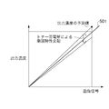
- FIG. 6B is a schematic diagram of gradation characteristic variation depending on the toner charge amount. The relationship between the density fluctuation of the maximum value 255 of the input image signal and the density fluctuation of other gradations is uniquely determined from the relation between the latent image, the toner charge amount, and the toner weight. Therefore, if the density of a certain gradation (here, the maximum density) is known, the entire gradation characteristic can be predicted.
- the ⁇ correction unit 1102 creates and stores a ⁇ -LUT having characteristics opposite to the obtained gradation characteristics. Further, ⁇ conversion processing is performed using this ⁇ -LUT. This makes it possible to correct changes in density gradation characteristics due to fluctuations in the toner charge amount.
- the density gradation characteristic is predicted by predicting the fluctuation of the toner charge amount from the toner consumption amount, the toner replenishment amount, and the toner agitation time, and by predicting the density gradation characteristic. Correction can be performed. Thereby, it is possible to always obtain an output image with stable density gradation characteristics. Then, basic gradation characteristics that have changed over a long period of time, such as deterioration over time of the image forming apparatus, can be corrected by the ⁇ conversion unit 1101, and gradation characteristics that have changed in a short time can be corrected by the ⁇ correction unit 1102. As a result, the gradation characteristics can always be maintained at a desired characteristic without reducing the throughput of patch creation.
- the method shown in FIG. 7A is used as gradation correction control by feedback control, but other feedback control such as forming a patch between prints and controlling gradation characteristics according to the density thereof. You may use together.
- patches are formed between prints without reducing throughput, the number of patches that can be formed is limited. Therefore, in order to perform gradation correction control as shown in FIG. 7A, a plurality of prints are required. Therefore, the gradation correction control shown in FIG. 7B is necessary.
- FIG. 13A is a block diagram illustrating a configuration example of the image forming apparatus according to the third embodiment. 13A is the same as the configuration of FIG. 5 except that the ⁇ correction unit 1102 is deleted from the configuration of FIG. 5 and an intensity correction unit 1300 is added to the configuration of FIG. Therefore, the operation of the intensity correction unit 1108 will be described below.
- the intensity correction unit 1108 receives the toner weight fluctuation amount ⁇ M at the maximum value 255 of the input image signal from the correction amount calculation unit 1106, and calculates the correction coefficient kp by calculating the following equation (15).
- M norm the target toner weight per unit area at the maximum value 255.
- the intensity correction unit 1108 multiplies the input signal by the correction coefficient Kp and outputs the result to the PWM processing unit 1104.
- the light emission intensity of the laser diode 1201 and the latent image formed on the photosensitive drum 1203 are changed by the above processing.
- the intensity of the latent image is proportional to the toner weight to be developed, and the toner charge amount is inversely proportional to the toner weight to be developed. Therefore, it is possible to correct the change in the toner charge amount with the intensity of the latent image. As described above, it is possible to always obtain an output image with stable density gradation characteristics.
- the example of controlling the ⁇ correction has been described.
- other image processing conditions such as HT (halftone) that can control the gradation may be controlled.
- the process conditions may be controlled based on the toner charge amount or the toner weight predicted by the correction amount calculation unit 1106. For example, as shown in the block diagram of FIG. 13B, it is possible to obtain a desired latent image by controlling the charging device 1205 and the developing device 1206 and adjusting the charge amount and developing bias of the photosensitive drum 1203. Further, more accurate control may be performed by combining image processing conditions and process conditions.
- the calculation of toner consumption is proportional to the video count value.
- a method that considers the density of pixel values and the relationship between the video count value and the toner consumption are stored in advance as an LUT. It is possible to use a method of calculating by doing so.
- the video count value is the signal integrated value after the HT processing, a method using the signal after the ⁇ correction processing may be used.
- the toner replenishment amount is determined by the video count value and the patch density.
- a method of using a sensor for detecting the toner amount in the developing device may be used.
- the toner charge amount varies according to the driving of the developing motor.
- the toner may be removed when the toner is left unattended for a long time.
- the toner charge amount can be obtained.
- the state space model is used for predicting the toner charge amount.
- other approximate models such as a transfer function and a differential equation can be used.
- a method of using a physical simulation for predicting the toner charge amount or a result of an experiment performed in advance can be considered. For example, when an LUT is used as the result of an experiment conducted in advance, the same is achieved by using a three-dimensional LUT that inputs toner charge amount, toner replenishment amount, and toner consumption amount, and outputs the change amount of toner charge amount after unit time. This processing result can be obtained.
- the ⁇ -LUT creation process is performed for each print according to the flowchart of FIG. 7B. You may make it produce (gamma) -LUT for every.
Landscapes
- Physics & Mathematics (AREA)
- General Physics & Mathematics (AREA)
- Engineering & Computer Science (AREA)
- Microelectronics & Electronic Packaging (AREA)
- Plasma & Fusion (AREA)
- Control Or Security For Electrophotography (AREA)
- Dry Development In Electrophotography (AREA)
Priority Applications (6)
| Application Number | Priority Date | Filing Date | Title |
|---|---|---|---|
| KR1020117008599A KR101260129B1 (ko) | 2008-09-25 | 2009-09-16 | 화상 형성 장치 및 화상 형성 방법 |
| EP09815854.6A EP2330465B1 (en) | 2008-09-25 | 2009-09-16 | Image forming device and image forming method |
| CN200980137953.XA CN102165376B (zh) | 2008-09-25 | 2009-09-16 | 图像形成设备和图像形成方法 |
| US13/046,020 US8335441B2 (en) | 2008-09-25 | 2011-03-11 | Image forming apparatus and image forming method |
| US13/690,039 US8611768B2 (en) | 2008-09-25 | 2012-11-30 | Image forming apparatus and image forming method |
| US14/079,813 US9057977B2 (en) | 2008-09-25 | 2013-11-14 | Image forming apparatus and image forming method |
Applications Claiming Priority (4)
| Application Number | Priority Date | Filing Date | Title |
|---|---|---|---|
| JP2008246593 | 2008-09-25 | ||
| JP2008-246593 | 2008-09-25 | ||
| JP2009-208601 | 2009-09-09 | ||
| JP2009208601A JP5173968B2 (ja) | 2008-09-25 | 2009-09-09 | 画像形成装置および画像形成方法 |
Related Child Applications (1)
| Application Number | Title | Priority Date | Filing Date |
|---|---|---|---|
| US13/046,020 Continuation US8335441B2 (en) | 2008-09-25 | 2011-03-11 | Image forming apparatus and image forming method |
Publications (1)
| Publication Number | Publication Date |
|---|---|
| WO2010035432A1 true WO2010035432A1 (ja) | 2010-04-01 |
Family
ID=42059445
Family Applications (1)
| Application Number | Title | Priority Date | Filing Date |
|---|---|---|---|
| PCT/JP2009/004638 Ceased WO2010035432A1 (ja) | 2008-09-25 | 2009-09-16 | 画像形成装置および画像形成方法 |
Country Status (6)
| Country | Link |
|---|---|
| US (3) | US8335441B2 (enExample) |
| EP (1) | EP2330465B1 (enExample) |
| JP (1) | JP5173968B2 (enExample) |
| KR (1) | KR101260129B1 (enExample) |
| CN (2) | CN104155862B (enExample) |
| WO (1) | WO2010035432A1 (enExample) |
Cited By (5)
| Publication number | Priority date | Publication date | Assignee | Title |
|---|---|---|---|---|
| WO2011145705A1 (en) * | 2010-05-18 | 2011-11-24 | Canon Kabushiki Kaisha | Image forming apparatus having stable image density |
| WO2011145704A1 (en) * | 2010-05-18 | 2011-11-24 | Canon Kabushiki Kaisha | Image forming apparatus capable of stabilizing image density on a short-term and long-term basis |
| CN102402154A (zh) * | 2010-09-14 | 2012-04-04 | 佳能株式会社 | 能够提供稳定的图像质量的图像形成设备 |
| JP2013130813A (ja) * | 2011-12-22 | 2013-07-04 | Fuji Xerox Co Ltd | 制御装置、画像形成装置、画像形成システム及びプログラム |
| JP2015026089A (ja) * | 2014-11-04 | 2015-02-05 | キヤノン株式会社 | 画像形成装置 |
Families Citing this family (23)
| Publication number | Priority date | Publication date | Assignee | Title |
|---|---|---|---|---|
| JP5173968B2 (ja) | 2008-09-25 | 2013-04-03 | キヤノン株式会社 | 画像形成装置および画像形成方法 |
| JP5739648B2 (ja) * | 2010-11-24 | 2015-06-24 | キヤノン株式会社 | 画像形成装置 |
| JP5875228B2 (ja) * | 2011-01-19 | 2016-03-02 | キヤノン株式会社 | 画像形成装置 |
| JP5734024B2 (ja) * | 2011-02-28 | 2015-06-10 | キヤノン株式会社 | 解析方法およびプログラム |
| JP5744569B2 (ja) * | 2011-02-28 | 2015-07-08 | キヤノン株式会社 | 粉体の混合比計算方法及び装置 |
| JP5744568B2 (ja) * | 2011-02-28 | 2015-07-08 | キヤノン株式会社 | 粉体の流動状態計算方法及び装置 |
| JP2014170197A (ja) | 2013-03-05 | 2014-09-18 | Canon Inc | 画像形成装置 |
| US9223278B2 (en) | 2013-03-06 | 2015-12-29 | Canon Kabushiki Kaisha | Image forming apparatus that performs gradation correction |
| JP2015081955A (ja) | 2013-10-21 | 2015-04-27 | キヤノン株式会社 | 測定装置、現像装置、および画像形成装置 |
| JP6214380B2 (ja) * | 2013-12-17 | 2017-10-18 | キヤノン株式会社 | 画像形成装置、及び、画像形成装置の制御方法 |
| JP6280378B2 (ja) | 2014-02-03 | 2018-02-14 | キヤノン株式会社 | 画像処理装置およびその制御方法 |
| KR20150108192A (ko) | 2014-03-17 | 2015-09-25 | 삼성전자주식회사 | 토너 절약 기능을 갖는 화상형성장치 및 그의 인쇄 방법 |
| JP6296018B2 (ja) * | 2015-08-05 | 2018-03-20 | コニカミノルタ株式会社 | 画像形成装置及びプログラム |
| JP6659118B2 (ja) * | 2015-10-30 | 2020-03-04 | キヤノン株式会社 | 画像形成装置 |
| JP6635815B2 (ja) | 2016-02-05 | 2020-01-29 | キヤノン株式会社 | 画像形成装置 |
| JP2017142342A (ja) * | 2016-02-09 | 2017-08-17 | キヤノン株式会社 | 画像形成装置 |
| JP6865368B2 (ja) * | 2017-02-23 | 2021-04-28 | 富士フイルムビジネスイノベーション株式会社 | 情報処理装置及び情報処理プログラム |
| JP2019028537A (ja) * | 2017-07-26 | 2019-02-21 | キヤノン株式会社 | 画像処理装置および画像処理方法 |
| JP7009918B2 (ja) * | 2017-10-30 | 2022-01-26 | コニカミノルタ株式会社 | 現像装置及び画像形成装置 |
| US10948842B2 (en) * | 2018-05-08 | 2021-03-16 | Canon Kabushiki Kaisha | Image forming apparatus |
| JP7183893B2 (ja) * | 2019-03-20 | 2022-12-06 | 株式会社リコー | 画像形成装置および画像形成ユニット |
| JP7375403B2 (ja) * | 2019-09-19 | 2023-11-08 | コニカミノルタ株式会社 | 機械学習装置、機械学習方法及び機械学習プログラム |
| JP7771142B2 (ja) * | 2023-09-05 | 2025-11-17 | キヤノン株式会社 | 画像形成装置 |
Citations (8)
| Publication number | Priority date | Publication date | Assignee | Title |
|---|---|---|---|---|
| JPH05303280A (ja) | 1992-04-24 | 1993-11-16 | Canon Inc | 画像形成装置 |
| JPH06130768A (ja) | 1992-10-14 | 1994-05-13 | Canon Inc | 画像形成装置 |
| JP2000238341A (ja) | 1999-02-24 | 2000-09-05 | Canon Inc | 画像処理装置及びその制御方法 |
| JP2004198805A (ja) * | 2002-12-19 | 2004-07-15 | Fuji Xerox Co Ltd | 画像形成装置 |
| JP2006301297A (ja) * | 2005-04-20 | 2006-11-02 | Sharp Corp | 電子写真装置およびその制御プログラム |
| JP2008191188A (ja) * | 2007-01-31 | 2008-08-21 | Canon Inc | 画像形成装置 |
| JP2008246593A (ja) | 2007-03-29 | 2008-10-16 | Topcon Corp | 研削水処理装置を有するレンズ研削加工装置 |
| JP2009208601A (ja) | 2008-03-04 | 2009-09-17 | Nissan Motor Co Ltd | 車線維持支援装置及び車線維持支援方法 |
Family Cites Families (24)
| Publication number | Priority date | Publication date | Assignee | Title |
|---|---|---|---|---|
| JPS56102874A (en) | 1980-01-19 | 1981-08-17 | Canon Inc | Developer replenishing device |
| US4422749A (en) | 1980-10-11 | 1983-12-27 | Canon Kabushiki Kaisha | Developing apparatus |
| US4970557A (en) * | 1987-09-02 | 1990-11-13 | Sharp Kabushiki Kaisha | Electrophotographic apparatus controlling image quality according to condition of deterioration |
| JP2991317B2 (ja) * | 1993-03-19 | 1999-12-20 | 富士通株式会社 | 画像形成装置 |
| JP2991098B2 (ja) * | 1995-12-28 | 1999-12-20 | 富士ゼロックス株式会社 | 画像形成装置および方法 |
| JP3589270B2 (ja) * | 1996-10-21 | 2004-11-17 | セイコーエプソン株式会社 | 画像形成方法 |
| JPH10142908A (ja) * | 1996-11-08 | 1998-05-29 | Fuji Xerox Co Ltd | 現像装置 |
| KR100370539B1 (ko) * | 1997-04-03 | 2005-01-15 | 가부시키가이샤 리코 | 화상형성장치및방법 |
| JP3541691B2 (ja) * | 1997-10-03 | 2004-07-14 | 株式会社リコー | 画像形成装置及び現像剤収納容器 |
| JPH11212343A (ja) * | 1998-01-29 | 1999-08-06 | Ricoh Co Ltd | 画像形成装置 |
| JP3292155B2 (ja) | 1998-09-04 | 2002-06-17 | キヤノン株式会社 | 画像形成装置 |
| DE10007885B4 (de) * | 1999-02-22 | 2016-08-18 | Kyocera Corp. | Bilderzeugungsverfahren und Bilderzeugungsvorrichtung |
| JP2001042613A (ja) * | 1999-07-28 | 2001-02-16 | Canon Inc | 現像装置及びこの現像装置を備える画像形成装置 |
| JP2002278176A (ja) | 2001-03-14 | 2002-09-27 | Canon Inc | 画像形成装置 |
| US6768878B2 (en) * | 2001-10-30 | 2004-07-27 | Konica Corporation | Image forming method and image forming apparatus utilizing a control patch |
| JP3626734B2 (ja) * | 2002-03-11 | 2005-03-09 | 日本電気株式会社 | 薄膜半導体装置 |
| US6792221B1 (en) * | 2003-03-14 | 2004-09-14 | Kabushiki Kaisha Toshiba | Image forming apparatus and method for revising image density |
| US7010237B2 (en) * | 2003-09-22 | 2006-03-07 | Canon Kabushiki Kaisha | Image forming apparatus with residual toner replenishing feature based on two detection results |
| JP4217671B2 (ja) | 2004-08-06 | 2009-02-04 | キヤノン株式会社 | 現像装置 |
| JP2006305827A (ja) * | 2005-04-27 | 2006-11-09 | Brother Ind Ltd | 画像形成システム及び画像形成装置 |
| JP2007033770A (ja) | 2005-07-26 | 2007-02-08 | Ricoh Co Ltd | 画像形成装置 |
| US7835653B2 (en) * | 2006-05-25 | 2010-11-16 | Ricoh Company, Limited | Developing device and image forming apparatus |
| JP4943131B2 (ja) * | 2006-12-13 | 2012-05-30 | シャープ株式会社 | 現像装置、画像形成装置、トナー補給方法、プログラムおよび記録媒体 |
| JP5173968B2 (ja) * | 2008-09-25 | 2013-04-03 | キヤノン株式会社 | 画像形成装置および画像形成方法 |
-
2009
- 2009-09-09 JP JP2009208601A patent/JP5173968B2/ja not_active Expired - Fee Related
- 2009-09-16 KR KR1020117008599A patent/KR101260129B1/ko not_active Expired - Fee Related
- 2009-09-16 CN CN201410389199.1A patent/CN104155862B/zh not_active Expired - Fee Related
- 2009-09-16 WO PCT/JP2009/004638 patent/WO2010035432A1/ja not_active Ceased
- 2009-09-16 CN CN200980137953.XA patent/CN102165376B/zh not_active Expired - Fee Related
- 2009-09-16 EP EP09815854.6A patent/EP2330465B1/en not_active Not-in-force
-
2011
- 2011-03-11 US US13/046,020 patent/US8335441B2/en not_active Expired - Fee Related
-
2012
- 2012-11-30 US US13/690,039 patent/US8611768B2/en not_active Expired - Fee Related
-
2013
- 2013-11-14 US US14/079,813 patent/US9057977B2/en not_active Expired - Fee Related
Patent Citations (8)
| Publication number | Priority date | Publication date | Assignee | Title |
|---|---|---|---|---|
| JPH05303280A (ja) | 1992-04-24 | 1993-11-16 | Canon Inc | 画像形成装置 |
| JPH06130768A (ja) | 1992-10-14 | 1994-05-13 | Canon Inc | 画像形成装置 |
| JP2000238341A (ja) | 1999-02-24 | 2000-09-05 | Canon Inc | 画像処理装置及びその制御方法 |
| JP2004198805A (ja) * | 2002-12-19 | 2004-07-15 | Fuji Xerox Co Ltd | 画像形成装置 |
| JP2006301297A (ja) * | 2005-04-20 | 2006-11-02 | Sharp Corp | 電子写真装置およびその制御プログラム |
| JP2008191188A (ja) * | 2007-01-31 | 2008-08-21 | Canon Inc | 画像形成装置 |
| JP2008246593A (ja) | 2007-03-29 | 2008-10-16 | Topcon Corp | 研削水処理装置を有するレンズ研削加工装置 |
| JP2009208601A (ja) | 2008-03-04 | 2009-09-17 | Nissan Motor Co Ltd | 車線維持支援装置及び車線維持支援方法 |
Cited By (10)
| Publication number | Priority date | Publication date | Assignee | Title |
|---|---|---|---|---|
| WO2011145705A1 (en) * | 2010-05-18 | 2011-11-24 | Canon Kabushiki Kaisha | Image forming apparatus having stable image density |
| WO2011145704A1 (en) * | 2010-05-18 | 2011-11-24 | Canon Kabushiki Kaisha | Image forming apparatus capable of stabilizing image density on a short-term and long-term basis |
| JP2011242596A (ja) * | 2010-05-18 | 2011-12-01 | Canon Inc | 画像形成装置 |
| JP2011242595A (ja) * | 2010-05-18 | 2011-12-01 | Canon Inc | 画像形成装置 |
| EP2572247A4 (en) * | 2010-05-18 | 2013-12-25 | Canon Kk | APPARATUS FOR FORMING IMAGES HAVING STABLE IMAGE DENSITY |
| US9280113B2 (en) | 2010-05-18 | 2016-03-08 | Canon Kabushiki Kaisha | Image forming apparatus capable of stabilizing image density on a short-term and long-term basis |
| CN102402154A (zh) * | 2010-09-14 | 2012-04-04 | 佳能株式会社 | 能够提供稳定的图像质量的图像形成设备 |
| US9020376B2 (en) | 2010-09-14 | 2015-04-28 | Canon Kabushiki Kaisha | Image forming apparatus capable of providing stable image quality |
| JP2013130813A (ja) * | 2011-12-22 | 2013-07-04 | Fuji Xerox Co Ltd | 制御装置、画像形成装置、画像形成システム及びプログラム |
| JP2015026089A (ja) * | 2014-11-04 | 2015-02-05 | キヤノン株式会社 | 画像形成装置 |
Also Published As
| Publication number | Publication date |
|---|---|
| KR20110065521A (ko) | 2011-06-15 |
| US20140064749A1 (en) | 2014-03-06 |
| EP2330465B1 (en) | 2018-11-14 |
| CN104155862A (zh) | 2014-11-19 |
| US20110164888A1 (en) | 2011-07-07 |
| CN102165376A (zh) | 2011-08-24 |
| US8335441B2 (en) | 2012-12-18 |
| EP2330465A4 (en) | 2014-07-16 |
| KR101260129B1 (ko) | 2013-05-02 |
| JP2010102317A (ja) | 2010-05-06 |
| JP5173968B2 (ja) | 2013-04-03 |
| EP2330465A1 (en) | 2011-06-08 |
| US8611768B2 (en) | 2013-12-17 |
| US9057977B2 (en) | 2015-06-16 |
| CN104155862B (zh) | 2018-02-27 |
| CN102165376B (zh) | 2014-09-03 |
| US20130089346A1 (en) | 2013-04-11 |
Similar Documents
| Publication | Publication Date | Title |
|---|---|---|
| JP5173968B2 (ja) | 画像形成装置および画像形成方法 | |
| JP5804764B2 (ja) | 画像処理装置 | |
| JP2010271692A (ja) | 画像形成装置 | |
| US20100067932A1 (en) | Image forming apparatus | |
| JP5291244B2 (ja) | 画像形成装置および画像形成方法 | |
| US9223278B2 (en) | Image forming apparatus that performs gradation correction | |
| US7206525B2 (en) | Image forming apparatus, a toner counter and a calculation method of toner consumption | |
| US9523954B2 (en) | Image forming apparatus that performs developer replenishment | |
| JP2013182099A (ja) | 画像形成装置 | |
| JP2016090699A (ja) | 画像形成装置 | |
| JP5739648B2 (ja) | 画像形成装置 | |
| JP5875228B2 (ja) | 画像形成装置 | |
| JP5392200B2 (ja) | 画像形成装置 | |
| EP2887146B1 (en) | Image forming apparatus and method for controlling image forming apparatus | |
| KR20120056205A (ko) | 콘트라스트 전위의 설정을 제어하는 화상 형성 장치 | |
| JP5357508B2 (ja) | 画像形成装置及びその制御方法、プログラム | |
| JP5222221B2 (ja) | 画像形成装置及び画像特性調整方法 | |
| JP2013101410A (ja) | 画像形成装置及び画像特性調整方法 | |
| JP2000122354A (ja) | 画像形成装置 | |
| JP2017138546A (ja) | 画像形成装置及び画像形成方法 | |
| JP2014174231A (ja) | 画像形成装置 | |
| JP2014174230A (ja) | 画像形成装置 | |
| JPH05265297A (ja) | 画像形成装置 |
Legal Events
| Date | Code | Title | Description |
|---|---|---|---|
| WWE | Wipo information: entry into national phase |
Ref document number: 200980137953.X Country of ref document: CN |
|
| 121 | Ep: the epo has been informed by wipo that ep was designated in this application |
Ref document number: 09815854 Country of ref document: EP Kind code of ref document: A1 |
|
| WWE | Wipo information: entry into national phase |
Ref document number: 2009815854 Country of ref document: EP |
|
| NENP | Non-entry into the national phase |
Ref country code: DE |
|
| ENP | Entry into the national phase |
Ref document number: 20117008599 Country of ref document: KR Kind code of ref document: A |