WO2010032831A1 - 投写型映像表示装置及び表示システム - Google Patents
投写型映像表示装置及び表示システム Download PDFInfo
- Publication number
- WO2010032831A1 WO2010032831A1 PCT/JP2009/066388 JP2009066388W WO2010032831A1 WO 2010032831 A1 WO2010032831 A1 WO 2010032831A1 JP 2009066388 W JP2009066388 W JP 2009066388W WO 2010032831 A1 WO2010032831 A1 WO 2010032831A1
- Authority
- WO
- WIPO (PCT)
- Prior art keywords
- projection
- image
- display apparatus
- light source
- adjustment
- Prior art date
- Legal status (The legal status is an assumption and is not a legal conclusion. Google has not performed a legal analysis and makes no representation as to the accuracy of the status listed.)
- Ceased
Links
Images


Classifications
-
- G—PHYSICS
- G03—PHOTOGRAPHY; CINEMATOGRAPHY; ANALOGOUS TECHNIQUES USING WAVES OTHER THAN OPTICAL WAVES; ELECTROGRAPHY; HOLOGRAPHY
- G03B—APPARATUS OR ARRANGEMENTS FOR TAKING PHOTOGRAPHS OR FOR PROJECTING OR VIEWING THEM; APPARATUS OR ARRANGEMENTS EMPLOYING ANALOGOUS TECHNIQUES USING WAVES OTHER THAN OPTICAL WAVES; ACCESSORIES THEREFOR
- G03B21/00—Projectors or projection-type viewers; Accessories therefor
- G03B21/14—Details
- G03B21/28—Reflectors in projection beam
-
- G—PHYSICS
- G03—PHOTOGRAPHY; CINEMATOGRAPHY; ANALOGOUS TECHNIQUES USING WAVES OTHER THAN OPTICAL WAVES; ELECTROGRAPHY; HOLOGRAPHY
- G03B—APPARATUS OR ARRANGEMENTS FOR TAKING PHOTOGRAPHS OR FOR PROJECTING OR VIEWING THEM; APPARATUS OR ARRANGEMENTS EMPLOYING ANALOGOUS TECHNIQUES USING WAVES OTHER THAN OPTICAL WAVES; ACCESSORIES THEREFOR
- G03B21/00—Projectors or projection-type viewers; Accessories therefor
- G03B21/005—Projectors using an electronic spatial light modulator but not peculiar thereto
-
- G—PHYSICS
- G03—PHOTOGRAPHY; CINEMATOGRAPHY; ANALOGOUS TECHNIQUES USING WAVES OTHER THAN OPTICAL WAVES; ELECTROGRAPHY; HOLOGRAPHY
- G03B—APPARATUS OR ARRANGEMENTS FOR TAKING PHOTOGRAPHS OR FOR PROJECTING OR VIEWING THEM; APPARATUS OR ARRANGEMENTS EMPLOYING ANALOGOUS TECHNIQUES USING WAVES OTHER THAN OPTICAL WAVES; ACCESSORIES THEREFOR
- G03B21/00—Projectors or projection-type viewers; Accessories therefor
- G03B21/14—Details
- G03B21/145—Housing details, e.g. position adjustments thereof
-
- G—PHYSICS
- G09—EDUCATION; CRYPTOGRAPHY; DISPLAY; ADVERTISING; SEALS
- G09G—ARRANGEMENTS OR CIRCUITS FOR CONTROL OF INDICATING DEVICES USING STATIC MEANS TO PRESENT VARIABLE INFORMATION
- G09G3/00—Control arrangements or circuits, of interest only in connection with visual indicators other than cathode-ray tubes
- G09G3/001—Control arrangements or circuits, of interest only in connection with visual indicators other than cathode-ray tubes using specific devices not provided for in groups G09G3/02 - G09G3/36, e.g. using an intermediate record carrier such as a film slide; Projection systems; Display of non-alphanumerical information, solely or in combination with alphanumerical information, e.g. digital display on projected diapositive as background
-
- G—PHYSICS
- G09—EDUCATION; CRYPTOGRAPHY; DISPLAY; ADVERTISING; SEALS
- G09G—ARRANGEMENTS OR CIRCUITS FOR CONTROL OF INDICATING DEVICES USING STATIC MEANS TO PRESENT VARIABLE INFORMATION
- G09G5/00—Control arrangements or circuits for visual indicators common to cathode-ray tube indicators and other visual indicators
- G09G5/003—Details of a display terminal, the details relating to the control arrangement of the display terminal and to the interfaces thereto
-
- H—ELECTRICITY
- H04—ELECTRIC COMMUNICATION TECHNIQUE
- H04N—PICTORIAL COMMUNICATION, e.g. TELEVISION
- H04N9/00—Details of colour television systems
- H04N9/12—Picture reproducers
- H04N9/31—Projection devices for colour picture display, e.g. using electronic spatial light modulators [ESLM]
- H04N9/3129—Projection devices for colour picture display, e.g. using electronic spatial light modulators [ESLM] scanning a light beam on the display screen
-
- H—ELECTRICITY
- H04—ELECTRIC COMMUNICATION TECHNIQUE
- H04N—PICTORIAL COMMUNICATION, e.g. TELEVISION
- H04N9/00—Details of colour television systems
- H04N9/12—Picture reproducers
- H04N9/31—Projection devices for colour picture display, e.g. using electronic spatial light modulators [ESLM]
- H04N9/3179—Video signal processing therefor
- H04N9/3185—Geometric adjustment, e.g. keystone or convergence
-
- G—PHYSICS
- G09—EDUCATION; CRYPTOGRAPHY; DISPLAY; ADVERTISING; SEALS
- G09G—ARRANGEMENTS OR CIRCUITS FOR CONTROL OF INDICATING DEVICES USING STATIC MEANS TO PRESENT VARIABLE INFORMATION
- G09G2320/00—Control of display operating conditions
- G09G2320/02—Improving the quality of display appearance
-
- G—PHYSICS
- G09—EDUCATION; CRYPTOGRAPHY; DISPLAY; ADVERTISING; SEALS
- G09G—ARRANGEMENTS OR CIRCUITS FOR CONTROL OF INDICATING DEVICES USING STATIC MEANS TO PRESENT VARIABLE INFORMATION
- G09G2340/00—Aspects of display data processing
- G09G2340/04—Changes in size, position or resolution of an image
- G09G2340/0407—Resolution change, inclusive of the use of different resolutions for different screen areas
Definitions
- the present invention relates to a projection display apparatus and a display system having a projection element that projects light emitted from a light source onto a projection plane.
- a projection display apparatus having a light modulation element and a projection optical system that projects light emitted from the light modulation element is known.
- a projection display apparatus has an image adjustment function (for example, a keystone correction function) for adjusting an image formed on a projection surface by light emitted from a projection optical system on a projection surface such as a screen.
- the image adjustment function is executed by operating a button provided on the main body of the projection display apparatus or the remote controller.
- a video adjustment function is selected by a button operation from a menu screen including a list of various functions. Subsequently, the video adjustment function is set by button operation.
- Patent Document 1 a portable projection display apparatus has been proposed in order to expand the usage scene of the projection display apparatus.
- the installation location is frequently changed. For this reason, the use frequency of video adjustment functions such as a keystone correction function is high.
- the image adjustment function is associated with the lower layer of the menu function, and it is necessary to call the image adjustment function, and an operation (button for adjusting the image on the projection surface) Operation) is complicated.
- the projection display apparatus includes a main body (main body 110) having a light source (solid light source 152) and a projection element (projection element 154) that projects light emitted from the light source onto a projection surface. Is provided.
- the projection element is provided inside the main body.
- the main body unit is an adjustment tool (horizontal adjustment tool 112 and vertical adjustment tool 113) used exclusively for operation of a video adjustment function for adjusting an image formed by light emitted from the projection element on the projection plane.
- the projection display apparatus includes a support member (support member 120) that rotatably supports the main body about a plurality of axes, and the main body and the support member at an installation location. And a fixing tool (fixing tool 130) for fixing.
- the projection display apparatus further includes an image processing unit that controls the image adjustment function based on an adjustment signal input from the adjustment tool.
- the image projected on the projection plane is composed of a plurality of pixels having coordinates determined by rows along the horizontal direction and columns along the vertical direction.
- the image processing unit changes the number of pixels in the horizontal direction and changes the number of pixels in the vertical direction by converting a video signal input from an external device.
- the projection display apparatus further includes an image processing unit that controls the image adjustment function based on an adjustment signal input from the adjustment tool.
- the image projected on the projection plane is composed of a plurality of pixels having coordinates determined by rows along the horizontal direction and columns along the vertical direction.
- the image processing unit outputs an adjustment signal input from the adjustment tool to an external device as a video signal conversion request.
- the image processing unit acquires the converted video signal from the external device.
- the converted video signal is a signal for changing the number of pixels in the horizontal direction and changing the number of pixels in the vertical direction.
- the projection display apparatus further includes an image processing unit that controls the image adjustment function based on an adjustment signal input from the adjustment tool.
- the light source is a solid light source.
- the projection element scans the projection plane along a predetermined scanning direction for each of a plurality of pixels having coordinates determined by a row along a horizontal direction and a column along a vertical direction.
- the image processing unit controls a scanning interval of the projection element in the predetermined scanning direction.
- the projection display apparatus includes a projection angle that is an angle at which the projection element projects light onto the projection surface, and a plurality of corrections in which a predetermined reference shape is deformed according to the projection angle.
- the light source and the projection so as to configure the plurality of correction shapes on the projection plane as an image constituted by a storage unit that stores the shape in association with the projection shape and the light projected on the projection plane.
- an image processing unit for controlling the elements.
- the projection display apparatus further includes an image processing unit that controls the light source and the projection element so that an image is formed by light projected onto the projection plane.
- the image processing unit completes the processing of the vertical guide line and the video adjustment function that form a perpendicular line when the processing of the video adjustment function is completed as the startup video when the projection display apparatus is started.
- the light source and the projection element are controlled so that a horizontal guide line constituting a horizontal line at the time is formed on the projection plane.
- the display system includes at least a projection display apparatus having a light source and a projection element that projects light emitted from the light source onto a projection plane.
- the display system includes an adjustment tool used for an operation of an image adjustment function for adjusting an image formed by light emitted from the projection element on the projection plane.
- the projection element is provided inside the projection display apparatus.
- FIG. 1 is a diagram illustrating a configuration of a display system according to the first embodiment.
- FIG. 2 is a diagram illustrating a configuration of the display system according to the first embodiment.
- FIG. 3 is a diagram illustrating a configuration of the display system according to the first embodiment.
- FIG. 4 is a diagram illustrating a configuration of the display system according to the first embodiment.
- FIG. 5 is a diagram showing a configuration of the projection display apparatus 100 according to the first embodiment.
- FIG. 6 is a diagram showing a configuration of the projection display apparatus 100 according to the first embodiment.
- FIG. 7 is a diagram illustrating functions of the display system according to the first embodiment.
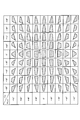
- FIG. 8 is a diagram for explaining the trapezoid correction function according to the first embodiment.
- FIG. 1 is a diagram illustrating a configuration of a display system according to the first embodiment.
- FIG. 2 is a diagram illustrating a configuration of the display system according to the first embodiment.
- FIG. 3 is a diagram illustrating a
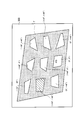
- FIG. 9 is a diagram for explaining the trapezoid correction function according to the first embodiment.
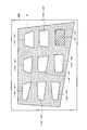
- FIG. 10 is a diagram for explaining the trapezoidal correction function according to the first embodiment.
- FIG. 11 is a diagram illustrating a configuration example of the adjustment tool according to the first modification of the first embodiment.
- FIG. 12 is a diagram illustrating a configuration example of the adjustment tool according to the first modification of the first embodiment.
- FIG. 13 is a diagram illustrating a configuration example of the adjustment tool according to the first modification of the first embodiment.
- FIG. 14 is a diagram illustrating a configuration example of the adjustment tool according to the first modification of the first embodiment.
- FIG. 15 is a diagram illustrating a configuration of a display system according to Modification 2 of the first embodiment.
- FIG. 16 is a diagram illustrating a configuration of a display system according to Modification 3 of the first embodiment.
- FIG. 17 is a diagram for explaining the trapezoidal correction function according to the third modification of the first embodiment.
- FIG. 18 is a diagram for explaining a trapezoid correction function according to Modification 3 of the first embodiment.
- FIG. 19 is a diagram illustrating functions of the display system according to the second embodiment.
- FIG. 20 is a diagram illustrating a correction shape according to the second embodiment.
- FIG. 21 is a diagram illustrating a display example of the correction shape according to the second embodiment.
- FIG. 22 is a diagram illustrating a display example of the correction shape according to the second embodiment.
- FIG. 23 is a diagram illustrating a display example of the correction shape according to the second embodiment.
- FIG. 24 is a diagram illustrating a display example of the correction shape according to the second embodiment.
- FIG. 25 is a diagram illustrating a display example after processing of the trapezoid correction function according to the second embodiment.
- FIG. 26 is a diagram illustrating a display example before processing of the trapezoid correction function according to the third embodiment.
- FIG. 27 is a diagram illustrating a display example after processing of the keystone correction function according to the third embodiment.
- a projection display apparatus includes a main body having a light source and a projection element that projects light emitted from the light source onto a projection surface.
- the projection element is provided inside the main body.
- the main body has an adjustment tool used exclusively for operation of an image adjustment function for adjusting an image formed by light emitted from the projection element on the projection surface.
- the projection display apparatus may be a portable apparatus attached to a terminal such as a notebook personal computer.
- the projection display apparatus includes a support member that rotatably supports the main body portion around a plurality of axes, and a fixture for fixing the main body portion and the support member to the installation location. It may be.
- the main body unit is provided with the adjustment tool used exclusively for the image adjustment function. Therefore, the operation for using the video adjustment function is simplified.
- an adjustment tool dedicated to the image adjustment function is provided in the main body. Should.
- a trapezoid correction function will be described as an example of the video adjustment function.
- the video adjustment function is not limited to the trapezoid correction function. That is, the image adjustment function may be any function that adjusts an image formed by light emitted from the projection element on the projection surface.
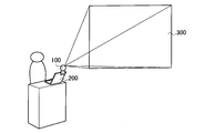
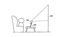
- FIGS. 1 to 3 are diagrams showing a configuration of a display system according to the first embodiment.
- the display system includes a projection display apparatus 100 and a terminal 200 such as a notebook PC.
- the projection display apparatus 100 is detachably fixed to the terminal 200.
- the projection display apparatus 100 projects image light on the projection plane 300.
- the projection plane 300 may be configured by a screen or may be configured by a simple wall surface.
- the projection display apparatus 100 may be used in a conference. Further, as shown in FIG. 2, the projection display apparatus 100 may be used in a presentation. Furthermore, as shown in FIG. 3, the projection display apparatus 100 may be used for personal use (home use).
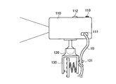
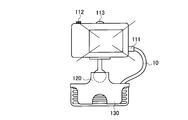
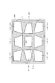
- FIGS. 4 to 6 are diagrams showing a configuration of the projection display apparatus 100 according to the first embodiment.
- the projection display apparatus 100 is detachably fixed to the terminal 200.
- the projection display apparatus 100 is connected to the terminal 200 by a cable 10 such as a USB cable.
- the projection display apparatus 100 has a port 111, and the terminal 200 has a port 211.
- the cable 10 connects the port 111 and the port 211.
- the projection display apparatus 100 may be connected to the terminal 200 wirelessly such as Bluetooth.
- the projection display apparatus 100 includes a main body 110, a support member 120, and a fixture 130.
- FIG. 5 is a view of the projection display apparatus 100 as viewed from the side.
- FIG. 6 is a diagram of the projection display apparatus 100 as viewed from the front.
- the main body 110 includes a solid light source 152 and a projection element 154 that projects light emitted from the solid light source 152 onto the projection plane 300.
- the main body 110 has the port 111 described above.
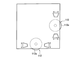
- the main body 110 includes a horizontal adjustment tool 112 and a vertical adjustment tool 113.
- the horizontal direction adjustment tool 112 and the vertical direction adjustment tool 113 are used exclusively for the trapezoidal correction function for correcting the shape of the image formed by the light emitted from the projection element 154 on the projection plane 300.
- An image composed of light emitted from the projection element 154 is composed of a plurality of pixels having coordinates determined by rows along the horizontal direction and columns along the vertical direction.
- the horizontal adjustment tool 112 is used to change the number of pixels in the horizontal direction.
- the horizontal adjustment tool 112 is configured to be rotatable. As will be described later, the pixels in the horizontal direction are thinned out or the pixels in the horizontal direction are interpolated by the rotation of the horizontal adjustment tool 112. That is, the number of pixels in the horizontal direction is changed for each row by the rotation of the horizontal adjustment tool 112.
- the horizontal adjustment tool 112 outputs a horizontal adjustment signal indicating the degree of pixel change in the horizontal direction in accordance with the rotation of the horizontal adjustment tool 112.
- the vertical adjustment tool 113 is used to change the number of pixels in the vertical direction.
- the vertical adjustment tool 113 is configured to be rotatable. As will be described later, the pixels in the vertical direction are thinned out or the pixels in the vertical direction are interpolated by the rotation of the vertical adjustment tool 113. That is, the number of pixels in the vertical direction is changed for each column by the rotation of the vertical adjustment tool 113.
- the vertical direction adjustment tool 113 outputs a vertical direction adjustment signal indicating the degree of pixel change in the vertical direction in accordance with the rotation of the vertical direction adjustment tool 113.
- the support member 120 supports the main body 110 so as to be rotatable.
- the support member 120 supports the main body 110 so as to be rotatable about at least a horizontal axis and a vertical axis.
- the support member 120 supports the main body 110 so as to be rotatable about an arbitrary axis (free axis).
- the fixing tool 130 is a member for fixing the main body 110 and the support member 120 to the terminal 200.
- the fixture 130 is a clip or the like.
- the fixture 130 is formed integrally with the support member 120.
- the fixing tool 130 includes a locking tool 131 that locks the cable 10.
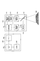
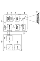
- FIG. 7 is a diagram illustrating functions of the display system according to the first embodiment.
- the display system includes the projection display apparatus 100 and the terminal 200.
- the terminal 200 includes a frame memory 251, a driver 252, and a display unit 253.
- the frame memory 251 stores video signals for a plurality of pixels constituting one frame.
- the video signal is composed of, for example, an R signal, a G signal, and a B signal.
- the driver 252 outputs video signals of a plurality of pixels constituting one frame to the projection display apparatus 100. Specifically, the driver 252 outputs a video signal via the cable 10 (not shown). As described above, the video signal includes, for example, an R signal, a G signal, and a B signal.
- the display unit 253 displays one frame of video based on the video signal stored in the frame memory 251. Note that the image displayed on the display unit 253 is preferably synchronized with the image projected on the projection plane 300.
- the projection display apparatus 100 includes an image processing unit 151, a solid light source 152, a solid light source driving unit 153, a projection element 154, and a projection element driving unit 155.
- the projection display apparatus 100 includes a horizontal direction adjustment tool 112 and a vertical direction adjustment tool 113.
- the image processing unit 151 processes the video signal acquired from the terminal 200.
- the image processing unit 151 has a trapezoidal correction function, a gamma correction function, and the like.
- the image processing unit 151 acquires a horizontal direction adjustment signal from the horizontal direction adjustment tool 112. Similarly, the image processing unit 151 acquires a vertical direction adjustment signal from the vertical direction adjustment tool 113.
- the image processing unit 151 controls the keystone correction function based on the horizontal direction adjustment signal input from the horizontal direction adjustment tool 112 and the vertical direction adjustment signal input from the vertical direction adjustment tool 113. Specifically, the image processing unit 151 converts the video signal acquired from the terminal 200 based on the horizontal direction adjustment signal and the vertical direction adjustment signal. That is, the image processing unit 151 constitutes an image processing unit that controls the trapezoid correction function.
- the image processing unit 151 performs pixel thinning processing in the horizontal direction, pixel interpolation processing in the horizontal direction, and the like according to the horizontal direction adjustment signal. Similarly, the image processing unit 151 performs pixel thinning processing in the vertical direction, pixel interpolation processing in the vertical direction, and the like according to the vertical direction adjustment signal.
- the solid light source 152 is a solid light source such as an LED (Laser Emitting Diode) or an LD (Laser Diode).
- the solid light source 152 includes a red solid light source, a green solid light source, and a blue solid light source.
- Each color solid light source may be an array light source constituted by a plurality of solid light sources.
- the solid light source driving unit 153 controls the solid light source 152 based on the video signal. Specifically, the solid-state light source driving unit 153 controls the driving power of the red solid-state light source based on the R signal, and controls the amount of red component light emitted from the red solid-state light source. The solid light source driving unit 153 controls the driving power of the green solid light source based on the G signal to control the amount of green component light emitted from the green solid light source. The solid state light source driving unit 153 controls the driving power of the blue solid state light source based on the B signal to control the amount of blue component light emitted from the blue solid state light source.
- the projection element 154 projects the light emitted from the solid light source driving unit 153 onto the projection plane 300. Specifically, the projection element 154 sequentially scans the projection plane 300 for each of a plurality of pixels along a predetermined scanning direction.
- the predetermined scanning direction may be a horizontal direction or a vertical direction.
- the projection element driving unit 155 controls the projection element 154 according to the video signal.
- the projection element driving unit 155 controls the scanning of the projection element 154 so as to make one round in one frame.
- the swing angle of the mirror provided in the projection element 154 remains constant.
- the interval between adjacent pixels in the horizontal direction is changed by changing the number of pixels in the horizontal direction.
- the swing angle of the mirror provided in the projection element 154 remains constant.
- the interval between adjacent pixels in the vertical direction is changed by changing the number of pixels in the vertical direction.
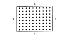
- FIG. 8 illustrates a case where the image shown in FIG. 8 is displayed on the projection plane 300 when the projection display apparatus 100 is provided in front of the projection plane 300 is illustrated. That is, FIG. 8 illustrates a case where the trapezoid correction function is not required.
- the projection display apparatus 100 changes the number of pixels in the horizontal direction.
- the projection display apparatus 100 reduces the width of the image in the horizontal direction as the upper line of the image is increased.
- the projection display apparatus 100 controls the width of the image in the horizontal direction by performing pixel thinning processing in the horizontal direction and pixel interpolation processing in the horizontal direction.
- an appropriate image is configured on the projection plane 300.
- the background display is, for example, white display or black display.
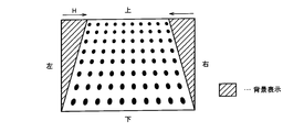
- the projection display apparatus 100 changes the number of pixels in the vertical direction.
- the projection display apparatus 100 decreases the height of the image in the vertical direction as the right column of the image.
- the projection display apparatus 100 controls the height of the image in the vertical direction by performing pixel thinning processing in the vertical direction and pixel interpolation processing in the vertical direction.
- an appropriate image is configured on the projection plane 300.
- the background display is, for example, white display or black display.
- the main body 110 is provided with a horizontal direction adjustment tool 112 and a vertical direction adjustment tool 113 that are used exclusively for the trapezoidal correction function. Therefore, the operation for using the trapezoidal correction function in the portable projection display 100 is simplified.
- the horizontal direction adjustment tool 112 and the vertical direction adjustment tool 113 used exclusively for the keystone correction function. It should be noted that is provided in the main body 110.
- the horizontal direction adjustment tool 112 and the vertical direction adjustment tool 113 include a rotation member 112 a and a rotation member 113 a configured to be rotatable.
- the horizontal direction adjustment tool 112 and the vertical direction adjustment tool 113 output a horizontal direction adjustment signal and a vertical direction adjustment signal according to the rotation of the rotation member 112a and the rotation member 113a.
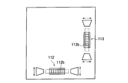
- the horizontal direction adjustment tool 112 and the vertical direction adjustment tool 113 have a rotation member 112b and a rotation member 113b that are configured to be rotatable.
- the horizontal direction adjustment tool 112 and the vertical direction adjustment tool 113 output a horizontal direction adjustment signal and a vertical direction adjustment signal in accordance with the rotation of the rotation member 112b and the rotation member 113b.
- the horizontal direction adjustment tool 112 and the vertical direction adjustment tool 113 include a slide member 112c and a slide member 113c configured to be slidable.
- the horizontal direction adjustment tool 112 and the vertical direction adjustment tool 113 output a horizontal direction adjustment signal and a vertical direction adjustment signal in accordance with the slide of the slide member 112c and the slide member 113c.
- the horizontal direction adjustment tool 112 and the vertical direction adjustment tool 113 include an operation button 112d, an operation button 112e, an operation button 113d, and an operation button 113e that are configured to be pressed.
- the horizontal direction adjustment tool 112 and the vertical direction adjustment tool 113 receive the horizontal direction adjustment signal and the vertical direction adjustment signal in response to pressing of the operation button 112d, the operation button 112e, the operation button 113d, and the operation button 113e. Output.
- the projection display apparatus 100 (image processing unit 151) issues a video signal conversion request in accordance with the horizontal direction adjustment signal and the vertical direction adjustment signal. Output to the terminal 200.
- the projection display apparatus 100 may output a horizontal direction adjustment signal and a vertical direction adjustment signal to the terminal 200 as a video signal conversion request.
- the terminal 200 converts the number of pixels in the horizontal direction and the number of pixels in the vertical direction in response to a video signal conversion request.
- the terminal 200 outputs the converted video signal to the projection display apparatus 100 (image processing unit 151).
- the converted video signal is a signal for changing the number of pixels in the horizontal direction and changing the number of pixels in the vertical direction.
- the trapezoidal correction function is realized not by converting the video signal but by controlling the scanning interval of the projection element 154.
- the projection element driving unit 155 acquires a horizontal direction adjustment signal from the horizontal direction adjustment tool 112 when the scanning direction of the projection element 154 is the horizontal direction. Note that the projection element driving unit 155 may acquire the vertical direction adjustment signal from the vertical direction adjustment tool 113 when the scanning direction of the projection element 154 is the vertical direction.
- the projection element driving unit 155 controls the keystone correction function based on the horizontal direction adjustment signal or the vertical direction adjustment signal. Specifically, when the scanning direction of the projection element 154 is the horizontal direction, the projection element driving unit 155 controls the scanning interval of the projection element 154 in the horizontal direction based on the horizontal direction adjustment signal. Note that, when the scanning direction of the projection element 154 is the vertical direction, the projection element driving unit 155 may control the scanning interval of the projection element 154 in the vertical direction based on the vertical direction adjustment signal.
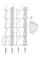
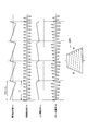
- the driving frequency (V) of the projection element 154 in the vertical direction and the driving frequency (H) of the projection element 154 in the horizontal direction are not particularly changed.
- the projection element driving unit 155 gradually decreases the swing angle (H) of the mirror provided in the projection element 154 by gradually decreasing the input current value (H) of the projection element 154 in the horizontal direction. As a result, the scanning interval of the projection element 154 becomes narrower in the lower row of the image.
- the driving frequency (V) of the projection element 154 in the vertical direction and the driving frequency (H) of the projection element 154 in the horizontal direction are not particularly changed.
- the projection element driving unit 155 gradually increases the swing angle (H) of the mirror provided in the projection element 154 by gradually increasing the input current value (H) of the projection element 154 in the horizontal direction. As a result, the scanning interval of the projection element 154 increases toward the lower line of the image.
- the image processing unit 151 converts the number of pixels in the vertical direction based on the vertical direction adjustment signal input from the vertical direction adjustment tool 113. It is preferable.
- the projection display apparatus 100 configures at least two or more correction shapes on the projection plane 300 as an image formed by light projected on the projection plane 300.
- the correction shape is a shape obtained by deforming the predetermined reference shape according to the projection angle.
- FIG. 19 is a diagram illustrating functions of the display system according to the second embodiment.
- FIG. 19 it should be noted that the same components as those in FIG. 19, it should be noted that the same components as those in FIG. 19, it should be noted that the same components as those in FIG. 19, it should be noted that the same components as those in FIG. 19, it should be noted that the same components as those in FIG. 19, it should be noted that the same components as those in FIG. 19, it should be noted that the same components as those in FIG.
- the projection display apparatus 100 includes a storage unit 156 in addition to the configuration shown in FIG.
- the storage unit 156 stores a plurality of correction shapes. Specifically, as illustrated in FIG. 20, the storage unit 156 includes a projection angle that is an angle at which the projection element 154 projects light onto the projection plane 300, and a plurality of predetermined reference shapes deformed according to the projection angle. The correction shape is stored in association with it.
- the predetermined reference shape is a light projection area configured by light projected on the projection plane 300 (for example, a rectangle or a horizontal / vertical ratio with an aspect ratio of 4: 3).
- a similar shape having a ratio of 16: 9 rectangle) is preferable.
- the correction shape is a shape deformed so that a predetermined reference shape is formed on the projection plane 300 when the projection angle is a projection angle associated with the correction shape.
- the correction shape is a light projection area (for example, a 4: 3 rectangle or 16: Nine rectangles) are preferable.
- the projection angle is represented by the pan angle from the reference projection angle and the tilt angle from the reference projection angle.
- the reference projection angle is a projection angle in which both the pan angle and the tilt angle are 0 °.
- the reference projection angle is a projection angle at which the optical axis of the projection display apparatus 100 matches the normal line of the projection plane 300.
- the correction shape associated with the reference projection angle is referred to as “correction shape STD”.
- the image processing unit 151 described above is configured so that at least two or more correction shapes among the plurality of correction shapes are configured on the projection plane 300 as an image configured by light projected on the projection plane 300.
- the solid-state light source driving unit 153 and the projection element driving unit 155 are controlled. That is, the image processing unit 151 indirectly controls the solid-state light source 152 and the projection element 154 so that at least two correction shapes among the plurality of correction shapes are configured on the projection plane 300.
- 21 to 25 are diagrams showing display examples of the correction shape according to the second embodiment.
- the correction shape STD on the projection plane 300 is a predetermined reference shape. Are different shapes.
- the horizontal direction adjustment tool 112 and the vertical direction adjustment tool 113 can be used.
- a key for example, a cursor key
- a key for example, a cursor key provided on the terminal 200 may be used.
- a key for example, a cursor key provided on the remote controller may be used.
- the projection display apparatus 100 displays, on the projection plane 300, a correction shape obtained by deforming a predetermined reference shape according to the projection angle as an image composed of light projected on the projection plane 300. Configure. Therefore, a correction shape similar to the predetermined reference shape may be selected on the projection plane 300, and image adjustment (trapezoid correction) can be easily performed.
- the projection display apparatus 100 uses a vertical guide that forms a vertical line when processing of the image adjustment function (trapezoid correction function) is completed as a startup image when the projection display apparatus 100 is started.
- a horizontal guide line constituting the horizontal line is configured on the projection plane 300.
- FIG. 26 and FIG. 27 are diagrams illustrating display examples of the start-up video according to the third embodiment. Specifically, FIG. 26 shows a startup video before the processing of the video adjustment function (keystone correction function) is completed, and FIG. 27 shows the startup after the processing of the video adjustment function (keystone correction function) is completed. A video is shown.
- the projection display apparatus 100 configures a vertical guide line 301 and a horizontal guide line 302 on the projection plane 300 as startup images when the projection display apparatus 100 is started.
- the projection display apparatus 100 may configure an initial image 303 such as a logo mark on the projection plane 300 as a startup image.
- the above-described image processing unit 151 controls the solid-state light source driving unit 153 and the projection element driving unit 155 so that the vertical guide line, the horizontal guide line, and the initial image 303 are configured on the projection plane 300 as the startup video. To do. That is, the image processing unit 151 indirectly controls the solid-state light source 152 and the projection element 154 so that the perpendicular guide line, the horizontal guide line, and the initial image 303 are configured on the projection plane 300.
- the vertical guide line 301 forms a vertical line when the image adjustment function (trapezoid correction function) is completed.
- the horizontal guide line 302 forms a horizontal line when the processing of the video adjustment function (trapezoid correction function) is completed.
- the vertical guide line 301 is not vertical, and the horizontal guide line 302 is not horizontal.
- the vertical guide line 301 is vertical, and the horizontal guide line 302 is horizontal.
- each of the vertical guide line 301 and the horizontal guide line 302 is one.
- the embodiment is not limited to this.
- a plurality of vertical guide lines 301 may be provided, and a plurality of horizontal guide lines 302 may be provided.
- a quadrangular shape may be constituted by a pair of vertical guide lines 301 and a pair of horizontal guide lines 302. That is, when the processing of the image adjustment function (trapezoid correction function) is completed, the pair of vertical guide lines 301 and the pair of horizontal guide lines 302 form a rectangular shape.
- the projection display apparatus 100 configures a vertical guide line 301 and a horizontal guide line 302 on the projection plane 300 as a startup image. Therefore, on the projection plane 300, the vertical guide lines 301 need only be aligned vertically and the horizontal guide lines 302 need only be aligned horizontally, and image adjustment (keystone correction) can be easily performed.
- video signal conversion and scanning interval control may be combined.
- the horizontal keystone correction function is realized by controlling the scanning interval of the projection element 154
- the vertical keystone correction function is realized by converting the video signal. May be.
- the trapezoid correction function in the vertical direction is realized by controlling the scanning interval of the projection element 154
- the trapezoid correction function in the horizontal direction is realized by converting the video signal. It may be realized.
- the portable projection display apparatus 100 is exemplified.
- the projection display apparatus 100 may be a stationary apparatus.
- the signal conversion of the trapezoid correction function is not described in detail, but it is needless to say that conversion of the video signal is necessary in addition to the number of pixels in accordance with the trapezoid correction.
- the embodiment is not limited to this.
- the operation I / F used for the operation of the video adjustment function may be provided in the terminal 200.
- the operation I / F provided in the terminal 200 may not be used exclusively for the operation of the video adjustment function.
- a solid light source is exemplified as the light source, but the light source is not limited to this. Specifically, the light source may be a UHP lamp or a xenon lamp.
- the present invention it is possible to provide a projection display apparatus and a display system that can simplify an operation for adjusting an image on a projection plane.
Landscapes
- Physics & Mathematics (AREA)
- Engineering & Computer Science (AREA)
- General Physics & Mathematics (AREA)
- Computer Hardware Design (AREA)
- Theoretical Computer Science (AREA)
- Multimedia (AREA)
- Signal Processing (AREA)
- Optics & Photonics (AREA)
- Geometry (AREA)
- Projection Apparatus (AREA)
- Transforming Electric Information Into Light Information (AREA)
Priority Applications (1)
| Application Number | Priority Date | Filing Date | Title |
|---|---|---|---|
| US13/051,381 US20110279456A1 (en) | 2008-09-19 | 2011-03-18 | Projection display apparatus and display system |
Applications Claiming Priority (4)
| Application Number | Priority Date | Filing Date | Title |
|---|---|---|---|
| JP2008-241525 | 2008-09-19 | ||
| JP2008241525 | 2008-09-19 | ||
| JP2009210255A JP2010098728A (ja) | 2008-09-19 | 2009-09-11 | 投写型映像表示装置及び表示システム |
| JP2009-210255 | 2009-09-11 |
Related Child Applications (1)
| Application Number | Title | Priority Date | Filing Date |
|---|---|---|---|
| US13/051,381 Continuation US20110279456A1 (en) | 2008-09-19 | 2011-03-18 | Projection display apparatus and display system |
Publications (1)
| Publication Number | Publication Date |
|---|---|
| WO2010032831A1 true WO2010032831A1 (ja) | 2010-03-25 |
Family
ID=42039652
Family Applications (1)
| Application Number | Title | Priority Date | Filing Date |
|---|---|---|---|
| PCT/JP2009/066388 Ceased WO2010032831A1 (ja) | 2008-09-19 | 2009-09-18 | 投写型映像表示装置及び表示システム |
Country Status (3)
| Country | Link |
|---|---|
| US (1) | US20110279456A1 (enExample) |
| JP (1) | JP2010098728A (enExample) |
| WO (1) | WO2010032831A1 (enExample) |
Families Citing this family (17)
| Publication number | Priority date | Publication date | Assignee | Title |
|---|---|---|---|---|
| US8885229B1 (en) | 2013-05-03 | 2014-11-11 | Kofax, Inc. | Systems and methods for detecting and classifying objects in video captured using mobile devices |
| US9769354B2 (en) | 2005-03-24 | 2017-09-19 | Kofax, Inc. | Systems and methods of processing scanned data |
| US9576272B2 (en) | 2009-02-10 | 2017-02-21 | Kofax, Inc. | Systems, methods and computer program products for determining document validity |
| US9767354B2 (en) | 2009-02-10 | 2017-09-19 | Kofax, Inc. | Global geographic information retrieval, validation, and normalization |
| JP5671901B2 (ja) * | 2010-09-15 | 2015-02-18 | セイコーエプソン株式会社 | 投射型表示装置およびその制御方法 |
| US10146795B2 (en) | 2012-01-12 | 2018-12-04 | Kofax, Inc. | Systems and methods for mobile image capture and processing |
| US9514357B2 (en) | 2012-01-12 | 2016-12-06 | Kofax, Inc. | Systems and methods for mobile image capture and processing |
| US9208536B2 (en) | 2013-09-27 | 2015-12-08 | Kofax, Inc. | Systems and methods for three dimensional geometric reconstruction of captured image data |
| US9355312B2 (en) | 2013-03-13 | 2016-05-31 | Kofax, Inc. | Systems and methods for classifying objects in digital images captured using mobile devices |
| US20140316841A1 (en) | 2013-04-23 | 2014-10-23 | Kofax, Inc. | Location-based workflows and services |
| WO2015073920A1 (en) | 2013-11-15 | 2015-05-21 | Kofax, Inc. | Systems and methods for generating composite images of long documents using mobile video data |
| US9760788B2 (en) | 2014-10-30 | 2017-09-12 | Kofax, Inc. | Mobile document detection and orientation based on reference object characteristics |
| US10242285B2 (en) | 2015-07-20 | 2019-03-26 | Kofax, Inc. | Iterative recognition-guided thresholding and data extraction |
| US10467465B2 (en) | 2015-07-20 | 2019-11-05 | Kofax, Inc. | Range and/or polarity-based thresholding for improved data extraction |
| US9779296B1 (en) | 2016-04-01 | 2017-10-03 | Kofax, Inc. | Content-based detection and three dimensional geometric reconstruction of objects in image and video data |
| US11062176B2 (en) | 2017-11-30 | 2021-07-13 | Kofax, Inc. | Object detection and image cropping using a multi-detector approach |
| US11899834B2 (en) * | 2019-12-27 | 2024-02-13 | Sony Group Corporation | Information processing device and method |
Citations (6)
| Publication number | Priority date | Publication date | Assignee | Title |
|---|---|---|---|---|
| JP2001069433A (ja) * | 1999-08-25 | 2001-03-16 | Ricoh Co Ltd | 画像投影装置、画像投影方法およびその方法をコンピュータに実行させるプログラムを記録したコンピュータ読み取り可能な記録媒体 |
| JP2002158897A (ja) * | 2000-11-17 | 2002-05-31 | Sharp Corp | ビデオカメラ |
| JP2003153133A (ja) * | 2001-07-30 | 2003-05-23 | Sony Corp | プロジェクタおよび画像補正方法 |
| JP2005033686A (ja) * | 2003-07-11 | 2005-02-03 | Casio Comput Co Ltd | 台形歪み補正方法、及びプロジェクタ |
| JP2006313259A (ja) * | 2005-05-09 | 2006-11-16 | Seiko Epson Corp | プロジェクタへの画像の供給 |
| WO2007001680A1 (en) * | 2005-06-24 | 2007-01-04 | Symbol Technologies, Inc. | Correcting for image distortion in image projectors |
Family Cites Families (18)
| Publication number | Priority date | Publication date | Assignee | Title |
|---|---|---|---|---|
| JPH05276227A (ja) * | 1992-03-27 | 1993-10-22 | Daini Denden Kk | 端末装置における呼出音量設定方式 |
| EP0645736B1 (en) * | 1993-09-27 | 2003-02-05 | Canon Kabushiki Kaisha | Image processing apparatus |
| JP3667025B2 (ja) * | 1997-02-28 | 2005-07-06 | キヤノン株式会社 | 解像度変換モジュールとそれが組み込まれたプリンタドライバ、及びその画像解像度変換方法 |
| WO2003107090A1 (en) * | 2002-06-12 | 2003-12-24 | Silicon Optix, Inc. | Automatic keystone correction system and method |
| US20060170669A1 (en) * | 2002-08-12 | 2006-08-03 | Walker Jay S | Digital picture frame and method for editing |
| JP3711973B2 (ja) * | 2002-10-09 | 2005-11-02 | 株式会社日立製作所 | 投射型表示装置 |
| JP4037816B2 (ja) * | 2003-10-06 | 2008-01-23 | Necディスプレイソリューションズ株式会社 | プロジェクタおよびプロジェクタによる画面の投射方法 |
| JP2005210418A (ja) * | 2004-01-22 | 2005-08-04 | Sanyo Electric Co Ltd | 画像処理装置、画像処理方法、画像処理プログラム |
| JP2005223393A (ja) * | 2004-02-03 | 2005-08-18 | Casio Comput Co Ltd | 投影装置、投影方法、及び投影プログラム |
| JP4617960B2 (ja) * | 2005-03-29 | 2011-01-26 | ブラザー工業株式会社 | 投影装置 |
| US8174627B2 (en) * | 2005-09-06 | 2012-05-08 | Hewlett-Packard Development Company, L.P. | Selectively masking image data |
| US20070099469A1 (en) * | 2005-11-03 | 2007-05-03 | Nite Ize, Inc. | General purpose magnetic connector |
| JP4635892B2 (ja) * | 2006-02-09 | 2011-02-23 | セイコーエプソン株式会社 | プロジェクションシステム、プロジェクタ、画像処理プログラム、および、画像処理プログラムを記録した記録媒体 |
| KR101225063B1 (ko) * | 2006-04-04 | 2013-01-24 | 삼성전자주식회사 | 투사되는 영상을 은닉적으로 보정하는 방법 및 이를 위한장치 |
| JP3129976U (ja) * | 2006-12-26 | 2007-03-08 | 株式会社島津製作所 | X線透視撮影装置 |
| US20090153749A1 (en) * | 2007-12-14 | 2009-06-18 | Stephen Randall Mixon | Portable projector background color correction scheme |
| US8591039B2 (en) * | 2008-10-28 | 2013-11-26 | Smart Technologies Ulc | Image projection methods and interactive input/projection systems employing the same |
| JP5401940B2 (ja) * | 2008-11-17 | 2014-01-29 | セイコーエプソン株式会社 | 投写光学系のズーム比測定方法、そのズーム比測定方法を用いた投写画像の補正方法及びその補正方法を実行するプロジェクタ |
-
2009
- 2009-09-11 JP JP2009210255A patent/JP2010098728A/ja active Pending
- 2009-09-18 WO PCT/JP2009/066388 patent/WO2010032831A1/ja not_active Ceased
-
2011
- 2011-03-18 US US13/051,381 patent/US20110279456A1/en not_active Abandoned
Patent Citations (6)
| Publication number | Priority date | Publication date | Assignee | Title |
|---|---|---|---|---|
| JP2001069433A (ja) * | 1999-08-25 | 2001-03-16 | Ricoh Co Ltd | 画像投影装置、画像投影方法およびその方法をコンピュータに実行させるプログラムを記録したコンピュータ読み取り可能な記録媒体 |
| JP2002158897A (ja) * | 2000-11-17 | 2002-05-31 | Sharp Corp | ビデオカメラ |
| JP2003153133A (ja) * | 2001-07-30 | 2003-05-23 | Sony Corp | プロジェクタおよび画像補正方法 |
| JP2005033686A (ja) * | 2003-07-11 | 2005-02-03 | Casio Comput Co Ltd | 台形歪み補正方法、及びプロジェクタ |
| JP2006313259A (ja) * | 2005-05-09 | 2006-11-16 | Seiko Epson Corp | プロジェクタへの画像の供給 |
| WO2007001680A1 (en) * | 2005-06-24 | 2007-01-04 | Symbol Technologies, Inc. | Correcting for image distortion in image projectors |
Also Published As
| Publication number | Publication date |
|---|---|
| US20110279456A1 (en) | 2011-11-17 |
| JP2010098728A (ja) | 2010-04-30 |
Similar Documents
| Publication | Publication Date | Title |
|---|---|---|
| WO2010032831A1 (ja) | 投写型映像表示装置及び表示システム | |
| JP6164820B2 (ja) | プロジェクタ、その制御方法、及び画像投影システム | |
| US9554105B2 (en) | Projection type image display apparatus and control method therefor | |
| US10431131B2 (en) | Projector and control method for projector | |
| JP6364899B2 (ja) | プロジェクター、プロジェクターの制御方法、および、プログラム | |
| US9811876B2 (en) | Display apparatus and control method | |
| JP2012108479A (ja) | 投射型表示装置及びその制御方法 | |
| JP2014187532A (ja) | 投影装置、投影方法及び投影プログラム | |
| JP2014187512A (ja) | 投影装置、投影方法、及び投影のためのプログラム | |
| JP6707871B2 (ja) | 画質補正方法、及び、画像投射システム | |
| JP2006165949A (ja) | プロジェクタシステムおよびプロジェクタ | |
| JP2013083755A (ja) | 表示装置、表示装置の制御方法、プログラム | |
| JP5217194B2 (ja) | プロジェクタ | |
| JP2017085446A (ja) | 投影装置、投影方法及び投影システム | |
| JP2019047355A (ja) | プロジェクタ | |
| US10847121B2 (en) | Display apparatus and method for controlling display apparatus displaying image with superimposed mask | |
| JP6665543B2 (ja) | プロジェクター、及び、撮像画像の補正方法 | |
| JP6700955B2 (ja) | 投影装置及び投影方法 | |
| JP2012070031A (ja) | 画像表示システム、撮像装置、画像表示システムの制御方法、および撮像装置の制御方法 | |
| JP6345316B2 (ja) | プロジェクタ、その制御方法、プログラム、及び記憶媒体 | |
| JP2021105642A (ja) | 表示システムの制御方法、及び表示システム | |
| US11132768B2 (en) | Method for controlling display device, display device, and display system | |
| JP2008112035A (ja) | プロジェクタ | |
| JP2011221128A (ja) | 投写型映像表示装置 | |
| JP2022176643A (ja) | 表示装置 |
Legal Events
| Date | Code | Title | Description |
|---|---|---|---|
| 121 | Ep: the epo has been informed by wipo that ep was designated in this application |
Ref document number: 09814675 Country of ref document: EP Kind code of ref document: A1 |
|
| NENP | Non-entry into the national phase |
Ref country code: DE |
|
| 122 | Ep: pct application non-entry in european phase |
Ref document number: 09814675 Country of ref document: EP Kind code of ref document: A1 |