WO2010032831A1 - Projection type video image display device and display system - Google Patents
Projection type video image display device and display system Download PDFInfo
- Publication number
- WO2010032831A1 WO2010032831A1 PCT/JP2009/066388 JP2009066388W WO2010032831A1 WO 2010032831 A1 WO2010032831 A1 WO 2010032831A1 JP 2009066388 W JP2009066388 W JP 2009066388W WO 2010032831 A1 WO2010032831 A1 WO 2010032831A1
- Authority
- WO
- WIPO (PCT)
- Prior art keywords
- projection
- image
- display apparatus
- light source
- adjustment
- Prior art date
Links
Images


Classifications
-
- G—PHYSICS
- G03—PHOTOGRAPHY; CINEMATOGRAPHY; ANALOGOUS TECHNIQUES USING WAVES OTHER THAN OPTICAL WAVES; ELECTROGRAPHY; HOLOGRAPHY
- G03B—APPARATUS OR ARRANGEMENTS FOR TAKING PHOTOGRAPHS OR FOR PROJECTING OR VIEWING THEM; APPARATUS OR ARRANGEMENTS EMPLOYING ANALOGOUS TECHNIQUES USING WAVES OTHER THAN OPTICAL WAVES; ACCESSORIES THEREFOR
- G03B21/00—Projectors or projection-type viewers; Accessories therefor
- G03B21/14—Details
- G03B21/28—Reflectors in projection beam
-
- G—PHYSICS
- G03—PHOTOGRAPHY; CINEMATOGRAPHY; ANALOGOUS TECHNIQUES USING WAVES OTHER THAN OPTICAL WAVES; ELECTROGRAPHY; HOLOGRAPHY
- G03B—APPARATUS OR ARRANGEMENTS FOR TAKING PHOTOGRAPHS OR FOR PROJECTING OR VIEWING THEM; APPARATUS OR ARRANGEMENTS EMPLOYING ANALOGOUS TECHNIQUES USING WAVES OTHER THAN OPTICAL WAVES; ACCESSORIES THEREFOR
- G03B21/00—Projectors or projection-type viewers; Accessories therefor
- G03B21/005—Projectors using an electronic spatial light modulator but not peculiar thereto
-
- G—PHYSICS
- G03—PHOTOGRAPHY; CINEMATOGRAPHY; ANALOGOUS TECHNIQUES USING WAVES OTHER THAN OPTICAL WAVES; ELECTROGRAPHY; HOLOGRAPHY
- G03B—APPARATUS OR ARRANGEMENTS FOR TAKING PHOTOGRAPHS OR FOR PROJECTING OR VIEWING THEM; APPARATUS OR ARRANGEMENTS EMPLOYING ANALOGOUS TECHNIQUES USING WAVES OTHER THAN OPTICAL WAVES; ACCESSORIES THEREFOR
- G03B21/00—Projectors or projection-type viewers; Accessories therefor
- G03B21/14—Details
- G03B21/145—Housing details, e.g. position adjustments thereof
-
- G—PHYSICS
- G09—EDUCATION; CRYPTOGRAPHY; DISPLAY; ADVERTISING; SEALS
- G09G—ARRANGEMENTS OR CIRCUITS FOR CONTROL OF INDICATING DEVICES USING STATIC MEANS TO PRESENT VARIABLE INFORMATION
- G09G3/00—Control arrangements or circuits, of interest only in connection with visual indicators other than cathode-ray tubes
- G09G3/001—Control arrangements or circuits, of interest only in connection with visual indicators other than cathode-ray tubes using specific devices not provided for in groups G09G3/02 - G09G3/36, e.g. using an intermediate record carrier such as a film slide; Projection systems; Display of non-alphanumerical information, solely or in combination with alphanumerical information, e.g. digital display on projected diapositive as background
-
- G—PHYSICS
- G09—EDUCATION; CRYPTOGRAPHY; DISPLAY; ADVERTISING; SEALS
- G09G—ARRANGEMENTS OR CIRCUITS FOR CONTROL OF INDICATING DEVICES USING STATIC MEANS TO PRESENT VARIABLE INFORMATION
- G09G5/00—Control arrangements or circuits for visual indicators common to cathode-ray tube indicators and other visual indicators
- G09G5/003—Details of a display terminal, the details relating to the control arrangement of the display terminal and to the interfaces thereto
-
- H—ELECTRICITY
- H04—ELECTRIC COMMUNICATION TECHNIQUE
- H04N—PICTORIAL COMMUNICATION, e.g. TELEVISION
- H04N9/00—Details of colour television systems
- H04N9/12—Picture reproducers
- H04N9/31—Projection devices for colour picture display, e.g. using electronic spatial light modulators [ESLM]
- H04N9/3129—Projection devices for colour picture display, e.g. using electronic spatial light modulators [ESLM] scanning a light beam on the display screen
-
- H—ELECTRICITY
- H04—ELECTRIC COMMUNICATION TECHNIQUE
- H04N—PICTORIAL COMMUNICATION, e.g. TELEVISION
- H04N9/00—Details of colour television systems
- H04N9/12—Picture reproducers
- H04N9/31—Projection devices for colour picture display, e.g. using electronic spatial light modulators [ESLM]
- H04N9/3179—Video signal processing therefor
- H04N9/3185—Geometric adjustment, e.g. keystone or convergence
-
- G—PHYSICS
- G09—EDUCATION; CRYPTOGRAPHY; DISPLAY; ADVERTISING; SEALS
- G09G—ARRANGEMENTS OR CIRCUITS FOR CONTROL OF INDICATING DEVICES USING STATIC MEANS TO PRESENT VARIABLE INFORMATION
- G09G2320/00—Control of display operating conditions
- G09G2320/02—Improving the quality of display appearance
-
- G—PHYSICS
- G09—EDUCATION; CRYPTOGRAPHY; DISPLAY; ADVERTISING; SEALS
- G09G—ARRANGEMENTS OR CIRCUITS FOR CONTROL OF INDICATING DEVICES USING STATIC MEANS TO PRESENT VARIABLE INFORMATION
- G09G2340/00—Aspects of display data processing
- G09G2340/04—Changes in size, position or resolution of an image
- G09G2340/0407—Resolution change, inclusive of the use of different resolutions for different screen areas
Definitions
- the present invention relates to a projection display apparatus and a display system having a projection element that projects light emitted from a light source onto a projection plane.
- a projection display apparatus having a light modulation element and a projection optical system that projects light emitted from the light modulation element is known.
- a projection display apparatus has an image adjustment function (for example, a keystone correction function) for adjusting an image formed on a projection surface by light emitted from a projection optical system on a projection surface such as a screen.
- the image adjustment function is executed by operating a button provided on the main body of the projection display apparatus or the remote controller.
- a video adjustment function is selected by a button operation from a menu screen including a list of various functions. Subsequently, the video adjustment function is set by button operation.
- Patent Document 1 a portable projection display apparatus has been proposed in order to expand the usage scene of the projection display apparatus.
- the installation location is frequently changed. For this reason, the use frequency of video adjustment functions such as a keystone correction function is high.
- the image adjustment function is associated with the lower layer of the menu function, and it is necessary to call the image adjustment function, and an operation (button for adjusting the image on the projection surface) Operation) is complicated.
- the projection display apparatus includes a main body (main body 110) having a light source (solid light source 152) and a projection element (projection element 154) that projects light emitted from the light source onto a projection surface. Is provided.
- the projection element is provided inside the main body.
- the main body unit is an adjustment tool (horizontal adjustment tool 112 and vertical adjustment tool 113) used exclusively for operation of a video adjustment function for adjusting an image formed by light emitted from the projection element on the projection plane.
- the projection display apparatus includes a support member (support member 120) that rotatably supports the main body about a plurality of axes, and the main body and the support member at an installation location. And a fixing tool (fixing tool 130) for fixing.
- the projection display apparatus further includes an image processing unit that controls the image adjustment function based on an adjustment signal input from the adjustment tool.
- the image projected on the projection plane is composed of a plurality of pixels having coordinates determined by rows along the horizontal direction and columns along the vertical direction.
- the image processing unit changes the number of pixels in the horizontal direction and changes the number of pixels in the vertical direction by converting a video signal input from an external device.
- the projection display apparatus further includes an image processing unit that controls the image adjustment function based on an adjustment signal input from the adjustment tool.
- the image projected on the projection plane is composed of a plurality of pixels having coordinates determined by rows along the horizontal direction and columns along the vertical direction.
- the image processing unit outputs an adjustment signal input from the adjustment tool to an external device as a video signal conversion request.
- the image processing unit acquires the converted video signal from the external device.
- the converted video signal is a signal for changing the number of pixels in the horizontal direction and changing the number of pixels in the vertical direction.
- the projection display apparatus further includes an image processing unit that controls the image adjustment function based on an adjustment signal input from the adjustment tool.
- the light source is a solid light source.
- the projection element scans the projection plane along a predetermined scanning direction for each of a plurality of pixels having coordinates determined by a row along a horizontal direction and a column along a vertical direction.
- the image processing unit controls a scanning interval of the projection element in the predetermined scanning direction.
- the projection display apparatus includes a projection angle that is an angle at which the projection element projects light onto the projection surface, and a plurality of corrections in which a predetermined reference shape is deformed according to the projection angle.
- the light source and the projection so as to configure the plurality of correction shapes on the projection plane as an image constituted by a storage unit that stores the shape in association with the projection shape and the light projected on the projection plane.
- an image processing unit for controlling the elements.
- the projection display apparatus further includes an image processing unit that controls the light source and the projection element so that an image is formed by light projected onto the projection plane.
- the image processing unit completes the processing of the vertical guide line and the video adjustment function that form a perpendicular line when the processing of the video adjustment function is completed as the startup video when the projection display apparatus is started.
- the light source and the projection element are controlled so that a horizontal guide line constituting a horizontal line at the time is formed on the projection plane.
- the display system includes at least a projection display apparatus having a light source and a projection element that projects light emitted from the light source onto a projection plane.
- the display system includes an adjustment tool used for an operation of an image adjustment function for adjusting an image formed by light emitted from the projection element on the projection plane.
- the projection element is provided inside the projection display apparatus.
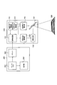
- FIG. 1 is a diagram illustrating a configuration of a display system according to the first embodiment.
- FIG. 2 is a diagram illustrating a configuration of the display system according to the first embodiment.
- FIG. 3 is a diagram illustrating a configuration of the display system according to the first embodiment.
- FIG. 4 is a diagram illustrating a configuration of the display system according to the first embodiment.
- FIG. 5 is a diagram showing a configuration of the projection display apparatus 100 according to the first embodiment.
- FIG. 6 is a diagram showing a configuration of the projection display apparatus 100 according to the first embodiment.
- FIG. 7 is a diagram illustrating functions of the display system according to the first embodiment.
- FIG. 8 is a diagram for explaining the trapezoid correction function according to the first embodiment.
- FIG. 1 is a diagram illustrating a configuration of a display system according to the first embodiment.
- FIG. 2 is a diagram illustrating a configuration of the display system according to the first embodiment.
- FIG. 3 is a diagram illustrating a
- FIG. 9 is a diagram for explaining the trapezoid correction function according to the first embodiment.
- FIG. 10 is a diagram for explaining the trapezoidal correction function according to the first embodiment.
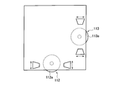
- FIG. 11 is a diagram illustrating a configuration example of the adjustment tool according to the first modification of the first embodiment.
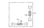
- FIG. 12 is a diagram illustrating a configuration example of the adjustment tool according to the first modification of the first embodiment.
- FIG. 13 is a diagram illustrating a configuration example of the adjustment tool according to the first modification of the first embodiment.
- FIG. 14 is a diagram illustrating a configuration example of the adjustment tool according to the first modification of the first embodiment.
- FIG. 15 is a diagram illustrating a configuration of a display system according to Modification 2 of the first embodiment.
- FIG. 16 is a diagram illustrating a configuration of a display system according to Modification 3 of the first embodiment.
- FIG. 17 is a diagram for explaining the trapezoidal correction function according to the third modification of the first embodiment.
- FIG. 18 is a diagram for explaining a trapezoid correction function according to Modification 3 of the first embodiment.
- FIG. 19 is a diagram illustrating functions of the display system according to the second embodiment.
- FIG. 20 is a diagram illustrating a correction shape according to the second embodiment.
- FIG. 21 is a diagram illustrating a display example of the correction shape according to the second embodiment.
- FIG. 22 is a diagram illustrating a display example of the correction shape according to the second embodiment.
- FIG. 23 is a diagram illustrating a display example of the correction shape according to the second embodiment.
- FIG. 24 is a diagram illustrating a display example of the correction shape according to the second embodiment.
- FIG. 25 is a diagram illustrating a display example after processing of the trapezoid correction function according to the second embodiment.
- FIG. 26 is a diagram illustrating a display example before processing of the trapezoid correction function according to the third embodiment.
- FIG. 27 is a diagram illustrating a display example after processing of the keystone correction function according to the third embodiment.
- a projection display apparatus includes a main body having a light source and a projection element that projects light emitted from the light source onto a projection surface.
- the projection element is provided inside the main body.
- the main body has an adjustment tool used exclusively for operation of an image adjustment function for adjusting an image formed by light emitted from the projection element on the projection surface.
- the projection display apparatus may be a portable apparatus attached to a terminal such as a notebook personal computer.
- the projection display apparatus includes a support member that rotatably supports the main body portion around a plurality of axes, and a fixture for fixing the main body portion and the support member to the installation location. It may be.
- the main body unit is provided with the adjustment tool used exclusively for the image adjustment function. Therefore, the operation for using the video adjustment function is simplified.
- an adjustment tool dedicated to the image adjustment function is provided in the main body. Should.
- a trapezoid correction function will be described as an example of the video adjustment function.
- the video adjustment function is not limited to the trapezoid correction function. That is, the image adjustment function may be any function that adjusts an image formed by light emitted from the projection element on the projection surface.
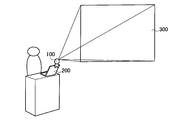
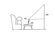
- FIGS. 1 to 3 are diagrams showing a configuration of a display system according to the first embodiment.
- the display system includes a projection display apparatus 100 and a terminal 200 such as a notebook PC.
- the projection display apparatus 100 is detachably fixed to the terminal 200.
- the projection display apparatus 100 projects image light on the projection plane 300.
- the projection plane 300 may be configured by a screen or may be configured by a simple wall surface.
- the projection display apparatus 100 may be used in a conference. Further, as shown in FIG. 2, the projection display apparatus 100 may be used in a presentation. Furthermore, as shown in FIG. 3, the projection display apparatus 100 may be used for personal use (home use).
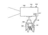
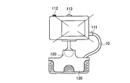
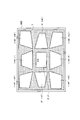
- FIGS. 4 to 6 are diagrams showing a configuration of the projection display apparatus 100 according to the first embodiment.
- the projection display apparatus 100 is detachably fixed to the terminal 200.
- the projection display apparatus 100 is connected to the terminal 200 by a cable 10 such as a USB cable.
- the projection display apparatus 100 has a port 111, and the terminal 200 has a port 211.
- the cable 10 connects the port 111 and the port 211.
- the projection display apparatus 100 may be connected to the terminal 200 wirelessly such as Bluetooth.
- the projection display apparatus 100 includes a main body 110, a support member 120, and a fixture 130.
- FIG. 5 is a view of the projection display apparatus 100 as viewed from the side.
- FIG. 6 is a diagram of the projection display apparatus 100 as viewed from the front.
- the main body 110 includes a solid light source 152 and a projection element 154 that projects light emitted from the solid light source 152 onto the projection plane 300.
- the main body 110 has the port 111 described above.
- the main body 110 includes a horizontal adjustment tool 112 and a vertical adjustment tool 113.
- the horizontal direction adjustment tool 112 and the vertical direction adjustment tool 113 are used exclusively for the trapezoidal correction function for correcting the shape of the image formed by the light emitted from the projection element 154 on the projection plane 300.
- An image composed of light emitted from the projection element 154 is composed of a plurality of pixels having coordinates determined by rows along the horizontal direction and columns along the vertical direction.
- the horizontal adjustment tool 112 is used to change the number of pixels in the horizontal direction.
- the horizontal adjustment tool 112 is configured to be rotatable. As will be described later, the pixels in the horizontal direction are thinned out or the pixels in the horizontal direction are interpolated by the rotation of the horizontal adjustment tool 112. That is, the number of pixels in the horizontal direction is changed for each row by the rotation of the horizontal adjustment tool 112.
- the horizontal adjustment tool 112 outputs a horizontal adjustment signal indicating the degree of pixel change in the horizontal direction in accordance with the rotation of the horizontal adjustment tool 112.
- the vertical adjustment tool 113 is used to change the number of pixels in the vertical direction.
- the vertical adjustment tool 113 is configured to be rotatable. As will be described later, the pixels in the vertical direction are thinned out or the pixels in the vertical direction are interpolated by the rotation of the vertical adjustment tool 113. That is, the number of pixels in the vertical direction is changed for each column by the rotation of the vertical adjustment tool 113.
- the vertical direction adjustment tool 113 outputs a vertical direction adjustment signal indicating the degree of pixel change in the vertical direction in accordance with the rotation of the vertical direction adjustment tool 113.
- the support member 120 supports the main body 110 so as to be rotatable.
- the support member 120 supports the main body 110 so as to be rotatable about at least a horizontal axis and a vertical axis.
- the support member 120 supports the main body 110 so as to be rotatable about an arbitrary axis (free axis).
- the fixing tool 130 is a member for fixing the main body 110 and the support member 120 to the terminal 200.
- the fixture 130 is a clip or the like.
- the fixture 130 is formed integrally with the support member 120.
- the fixing tool 130 includes a locking tool 131 that locks the cable 10.
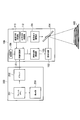
- FIG. 7 is a diagram illustrating functions of the display system according to the first embodiment.
- the display system includes the projection display apparatus 100 and the terminal 200.
- the terminal 200 includes a frame memory 251, a driver 252, and a display unit 253.
- the frame memory 251 stores video signals for a plurality of pixels constituting one frame.
- the video signal is composed of, for example, an R signal, a G signal, and a B signal.
- the driver 252 outputs video signals of a plurality of pixels constituting one frame to the projection display apparatus 100. Specifically, the driver 252 outputs a video signal via the cable 10 (not shown). As described above, the video signal includes, for example, an R signal, a G signal, and a B signal.
- the display unit 253 displays one frame of video based on the video signal stored in the frame memory 251. Note that the image displayed on the display unit 253 is preferably synchronized with the image projected on the projection plane 300.
- the projection display apparatus 100 includes an image processing unit 151, a solid light source 152, a solid light source driving unit 153, a projection element 154, and a projection element driving unit 155.
- the projection display apparatus 100 includes a horizontal direction adjustment tool 112 and a vertical direction adjustment tool 113.
- the image processing unit 151 processes the video signal acquired from the terminal 200.
- the image processing unit 151 has a trapezoidal correction function, a gamma correction function, and the like.
- the image processing unit 151 acquires a horizontal direction adjustment signal from the horizontal direction adjustment tool 112. Similarly, the image processing unit 151 acquires a vertical direction adjustment signal from the vertical direction adjustment tool 113.
- the image processing unit 151 controls the keystone correction function based on the horizontal direction adjustment signal input from the horizontal direction adjustment tool 112 and the vertical direction adjustment signal input from the vertical direction adjustment tool 113. Specifically, the image processing unit 151 converts the video signal acquired from the terminal 200 based on the horizontal direction adjustment signal and the vertical direction adjustment signal. That is, the image processing unit 151 constitutes an image processing unit that controls the trapezoid correction function.
- the image processing unit 151 performs pixel thinning processing in the horizontal direction, pixel interpolation processing in the horizontal direction, and the like according to the horizontal direction adjustment signal. Similarly, the image processing unit 151 performs pixel thinning processing in the vertical direction, pixel interpolation processing in the vertical direction, and the like according to the vertical direction adjustment signal.
- the solid light source 152 is a solid light source such as an LED (Laser Emitting Diode) or an LD (Laser Diode).
- the solid light source 152 includes a red solid light source, a green solid light source, and a blue solid light source.
- Each color solid light source may be an array light source constituted by a plurality of solid light sources.
- the solid light source driving unit 153 controls the solid light source 152 based on the video signal. Specifically, the solid-state light source driving unit 153 controls the driving power of the red solid-state light source based on the R signal, and controls the amount of red component light emitted from the red solid-state light source. The solid light source driving unit 153 controls the driving power of the green solid light source based on the G signal to control the amount of green component light emitted from the green solid light source. The solid state light source driving unit 153 controls the driving power of the blue solid state light source based on the B signal to control the amount of blue component light emitted from the blue solid state light source.
- the projection element 154 projects the light emitted from the solid light source driving unit 153 onto the projection plane 300. Specifically, the projection element 154 sequentially scans the projection plane 300 for each of a plurality of pixels along a predetermined scanning direction.
- the predetermined scanning direction may be a horizontal direction or a vertical direction.
- the projection element driving unit 155 controls the projection element 154 according to the video signal.
- the projection element driving unit 155 controls the scanning of the projection element 154 so as to make one round in one frame.
- the swing angle of the mirror provided in the projection element 154 remains constant.
- the interval between adjacent pixels in the horizontal direction is changed by changing the number of pixels in the horizontal direction.
- the swing angle of the mirror provided in the projection element 154 remains constant.
- the interval between adjacent pixels in the vertical direction is changed by changing the number of pixels in the vertical direction.
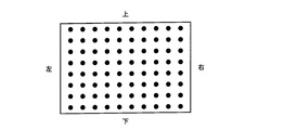
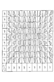
- FIG. 8 illustrates a case where the image shown in FIG. 8 is displayed on the projection plane 300 when the projection display apparatus 100 is provided in front of the projection plane 300 is illustrated. That is, FIG. 8 illustrates a case where the trapezoid correction function is not required.
- the projection display apparatus 100 changes the number of pixels in the horizontal direction.
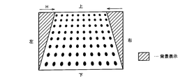
- the projection display apparatus 100 reduces the width of the image in the horizontal direction as the upper line of the image is increased.
- the projection display apparatus 100 controls the width of the image in the horizontal direction by performing pixel thinning processing in the horizontal direction and pixel interpolation processing in the horizontal direction.
- an appropriate image is configured on the projection plane 300.
- the background display is, for example, white display or black display.
- the projection display apparatus 100 changes the number of pixels in the vertical direction.
- the projection display apparatus 100 decreases the height of the image in the vertical direction as the right column of the image.
- the projection display apparatus 100 controls the height of the image in the vertical direction by performing pixel thinning processing in the vertical direction and pixel interpolation processing in the vertical direction.
- an appropriate image is configured on the projection plane 300.
- the background display is, for example, white display or black display.
- the main body 110 is provided with a horizontal direction adjustment tool 112 and a vertical direction adjustment tool 113 that are used exclusively for the trapezoidal correction function. Therefore, the operation for using the trapezoidal correction function in the portable projection display 100 is simplified.
- the horizontal direction adjustment tool 112 and the vertical direction adjustment tool 113 used exclusively for the keystone correction function. It should be noted that is provided in the main body 110.
- the horizontal direction adjustment tool 112 and the vertical direction adjustment tool 113 include a rotation member 112 a and a rotation member 113 a configured to be rotatable.
- the horizontal direction adjustment tool 112 and the vertical direction adjustment tool 113 output a horizontal direction adjustment signal and a vertical direction adjustment signal according to the rotation of the rotation member 112a and the rotation member 113a.
- the horizontal direction adjustment tool 112 and the vertical direction adjustment tool 113 have a rotation member 112b and a rotation member 113b that are configured to be rotatable.
- the horizontal direction adjustment tool 112 and the vertical direction adjustment tool 113 output a horizontal direction adjustment signal and a vertical direction adjustment signal in accordance with the rotation of the rotation member 112b and the rotation member 113b.
- the horizontal direction adjustment tool 112 and the vertical direction adjustment tool 113 include a slide member 112c and a slide member 113c configured to be slidable.
- the horizontal direction adjustment tool 112 and the vertical direction adjustment tool 113 output a horizontal direction adjustment signal and a vertical direction adjustment signal in accordance with the slide of the slide member 112c and the slide member 113c.
- the horizontal direction adjustment tool 112 and the vertical direction adjustment tool 113 include an operation button 112d, an operation button 112e, an operation button 113d, and an operation button 113e that are configured to be pressed.
- the horizontal direction adjustment tool 112 and the vertical direction adjustment tool 113 receive the horizontal direction adjustment signal and the vertical direction adjustment signal in response to pressing of the operation button 112d, the operation button 112e, the operation button 113d, and the operation button 113e. Output.
- the projection display apparatus 100 (image processing unit 151) issues a video signal conversion request in accordance with the horizontal direction adjustment signal and the vertical direction adjustment signal. Output to the terminal 200.
- the projection display apparatus 100 may output a horizontal direction adjustment signal and a vertical direction adjustment signal to the terminal 200 as a video signal conversion request.
- the terminal 200 converts the number of pixels in the horizontal direction and the number of pixels in the vertical direction in response to a video signal conversion request.
- the terminal 200 outputs the converted video signal to the projection display apparatus 100 (image processing unit 151).
- the converted video signal is a signal for changing the number of pixels in the horizontal direction and changing the number of pixels in the vertical direction.
- the trapezoidal correction function is realized not by converting the video signal but by controlling the scanning interval of the projection element 154.
- the projection element driving unit 155 acquires a horizontal direction adjustment signal from the horizontal direction adjustment tool 112 when the scanning direction of the projection element 154 is the horizontal direction. Note that the projection element driving unit 155 may acquire the vertical direction adjustment signal from the vertical direction adjustment tool 113 when the scanning direction of the projection element 154 is the vertical direction.
- the projection element driving unit 155 controls the keystone correction function based on the horizontal direction adjustment signal or the vertical direction adjustment signal. Specifically, when the scanning direction of the projection element 154 is the horizontal direction, the projection element driving unit 155 controls the scanning interval of the projection element 154 in the horizontal direction based on the horizontal direction adjustment signal. Note that, when the scanning direction of the projection element 154 is the vertical direction, the projection element driving unit 155 may control the scanning interval of the projection element 154 in the vertical direction based on the vertical direction adjustment signal.
- the driving frequency (V) of the projection element 154 in the vertical direction and the driving frequency (H) of the projection element 154 in the horizontal direction are not particularly changed.
- the projection element driving unit 155 gradually decreases the swing angle (H) of the mirror provided in the projection element 154 by gradually decreasing the input current value (H) of the projection element 154 in the horizontal direction. As a result, the scanning interval of the projection element 154 becomes narrower in the lower row of the image.
- the driving frequency (V) of the projection element 154 in the vertical direction and the driving frequency (H) of the projection element 154 in the horizontal direction are not particularly changed.
- the projection element driving unit 155 gradually increases the swing angle (H) of the mirror provided in the projection element 154 by gradually increasing the input current value (H) of the projection element 154 in the horizontal direction. As a result, the scanning interval of the projection element 154 increases toward the lower line of the image.
- the image processing unit 151 converts the number of pixels in the vertical direction based on the vertical direction adjustment signal input from the vertical direction adjustment tool 113. It is preferable.
- the projection display apparatus 100 configures at least two or more correction shapes on the projection plane 300 as an image formed by light projected on the projection plane 300.
- the correction shape is a shape obtained by deforming the predetermined reference shape according to the projection angle.
- FIG. 19 is a diagram illustrating functions of the display system according to the second embodiment.
- FIG. 19 it should be noted that the same components as those in FIG. 19, it should be noted that the same components as those in FIG. 19, it should be noted that the same components as those in FIG. 19, it should be noted that the same components as those in FIG. 19, it should be noted that the same components as those in FIG. 19, it should be noted that the same components as those in FIG. 19, it should be noted that the same components as those in FIG.
- the projection display apparatus 100 includes a storage unit 156 in addition to the configuration shown in FIG.
- the storage unit 156 stores a plurality of correction shapes. Specifically, as illustrated in FIG. 20, the storage unit 156 includes a projection angle that is an angle at which the projection element 154 projects light onto the projection plane 300, and a plurality of predetermined reference shapes deformed according to the projection angle. The correction shape is stored in association with it.
- the predetermined reference shape is a light projection area configured by light projected on the projection plane 300 (for example, a rectangle or a horizontal / vertical ratio with an aspect ratio of 4: 3).
- a similar shape having a ratio of 16: 9 rectangle) is preferable.
- the correction shape is a shape deformed so that a predetermined reference shape is formed on the projection plane 300 when the projection angle is a projection angle associated with the correction shape.
- the correction shape is a light projection area (for example, a 4: 3 rectangle or 16: Nine rectangles) are preferable.
- the projection angle is represented by the pan angle from the reference projection angle and the tilt angle from the reference projection angle.
- the reference projection angle is a projection angle in which both the pan angle and the tilt angle are 0 °.
- the reference projection angle is a projection angle at which the optical axis of the projection display apparatus 100 matches the normal line of the projection plane 300.
- the correction shape associated with the reference projection angle is referred to as “correction shape STD”.
- the image processing unit 151 described above is configured so that at least two or more correction shapes among the plurality of correction shapes are configured on the projection plane 300 as an image configured by light projected on the projection plane 300.
- the solid-state light source driving unit 153 and the projection element driving unit 155 are controlled. That is, the image processing unit 151 indirectly controls the solid-state light source 152 and the projection element 154 so that at least two correction shapes among the plurality of correction shapes are configured on the projection plane 300.
- 21 to 25 are diagrams showing display examples of the correction shape according to the second embodiment.
- the correction shape STD on the projection plane 300 is a predetermined reference shape. Are different shapes.
- the horizontal direction adjustment tool 112 and the vertical direction adjustment tool 113 can be used.
- a key for example, a cursor key
- a key for example, a cursor key provided on the terminal 200 may be used.
- a key for example, a cursor key provided on the remote controller may be used.
- the projection display apparatus 100 displays, on the projection plane 300, a correction shape obtained by deforming a predetermined reference shape according to the projection angle as an image composed of light projected on the projection plane 300. Configure. Therefore, a correction shape similar to the predetermined reference shape may be selected on the projection plane 300, and image adjustment (trapezoid correction) can be easily performed.
- the projection display apparatus 100 uses a vertical guide that forms a vertical line when processing of the image adjustment function (trapezoid correction function) is completed as a startup image when the projection display apparatus 100 is started.
- a horizontal guide line constituting the horizontal line is configured on the projection plane 300.
- FIG. 26 and FIG. 27 are diagrams illustrating display examples of the start-up video according to the third embodiment. Specifically, FIG. 26 shows a startup video before the processing of the video adjustment function (keystone correction function) is completed, and FIG. 27 shows the startup after the processing of the video adjustment function (keystone correction function) is completed. A video is shown.
- the projection display apparatus 100 configures a vertical guide line 301 and a horizontal guide line 302 on the projection plane 300 as startup images when the projection display apparatus 100 is started.
- the projection display apparatus 100 may configure an initial image 303 such as a logo mark on the projection plane 300 as a startup image.
- the above-described image processing unit 151 controls the solid-state light source driving unit 153 and the projection element driving unit 155 so that the vertical guide line, the horizontal guide line, and the initial image 303 are configured on the projection plane 300 as the startup video. To do. That is, the image processing unit 151 indirectly controls the solid-state light source 152 and the projection element 154 so that the perpendicular guide line, the horizontal guide line, and the initial image 303 are configured on the projection plane 300.
- the vertical guide line 301 forms a vertical line when the image adjustment function (trapezoid correction function) is completed.
- the horizontal guide line 302 forms a horizontal line when the processing of the video adjustment function (trapezoid correction function) is completed.
- the vertical guide line 301 is not vertical, and the horizontal guide line 302 is not horizontal.
- the vertical guide line 301 is vertical, and the horizontal guide line 302 is horizontal.
- each of the vertical guide line 301 and the horizontal guide line 302 is one.
- the embodiment is not limited to this.
- a plurality of vertical guide lines 301 may be provided, and a plurality of horizontal guide lines 302 may be provided.
- a quadrangular shape may be constituted by a pair of vertical guide lines 301 and a pair of horizontal guide lines 302. That is, when the processing of the image adjustment function (trapezoid correction function) is completed, the pair of vertical guide lines 301 and the pair of horizontal guide lines 302 form a rectangular shape.
- the projection display apparatus 100 configures a vertical guide line 301 and a horizontal guide line 302 on the projection plane 300 as a startup image. Therefore, on the projection plane 300, the vertical guide lines 301 need only be aligned vertically and the horizontal guide lines 302 need only be aligned horizontally, and image adjustment (keystone correction) can be easily performed.
- video signal conversion and scanning interval control may be combined.
- the horizontal keystone correction function is realized by controlling the scanning interval of the projection element 154
- the vertical keystone correction function is realized by converting the video signal. May be.
- the trapezoid correction function in the vertical direction is realized by controlling the scanning interval of the projection element 154
- the trapezoid correction function in the horizontal direction is realized by converting the video signal. It may be realized.
- the portable projection display apparatus 100 is exemplified.
- the projection display apparatus 100 may be a stationary apparatus.
- the signal conversion of the trapezoid correction function is not described in detail, but it is needless to say that conversion of the video signal is necessary in addition to the number of pixels in accordance with the trapezoid correction.
- the embodiment is not limited to this.
- the operation I / F used for the operation of the video adjustment function may be provided in the terminal 200.
- the operation I / F provided in the terminal 200 may not be used exclusively for the operation of the video adjustment function.
- a solid light source is exemplified as the light source, but the light source is not limited to this. Specifically, the light source may be a UHP lamp or a xenon lamp.
- the present invention it is possible to provide a projection display apparatus and a display system that can simplify an operation for adjusting an image on a projection plane.
Abstract
A projection type video image display device is provided with a main body unit comprised of a light source and a projection element for projecting light emitted from the light source to a projection plane. The projection element is provided in the main body unit. The main body unit is further comprised of an adjustment component exclusively used for the operation of a video image adjustment function to adjust a video image on the projection plane, wherein the video image is composed of the light emitted from the projection element.
Description
本発明は、光源から出射される光を投写面上に投写する投写素子を有する投写型映像表示装置及び表示システムに関する。
The present invention relates to a projection display apparatus and a display system having a projection element that projects light emitted from a light source onto a projection plane.
従来、光変調素子と、光変調素子から出射される光を投写する投写光学系とを有する投写型映像表示装置が知られている。投写型映像表示装置は、スクリーンなどの投写面上において、投写光学系から出射された光によって投写面上に構成される映像を調整する映像調整機能(例えば、台形補正機能)を有する。
2. Description of the Related Art Conventionally, a projection display apparatus having a light modulation element and a projection optical system that projects light emitted from the light modulation element is known. A projection display apparatus has an image adjustment function (for example, a keystone correction function) for adjusting an image formed on a projection surface by light emitted from a projection optical system on a projection surface such as a screen.
ところで、一般的には、映像調整機能は、投写型映像表示装置の本体やリモートコントローラに設けられたボタンの操作によって実行される。例えば、各種機能の一覧を含むメニュー画面の中から、映像調整機能がボタン操作によって選択される。続いて、映像調整機能の設定がボタン操作によって行われる。
By the way, in general, the image adjustment function is executed by operating a button provided on the main body of the projection display apparatus or the remote controller. For example, a video adjustment function is selected by a button operation from a menu screen including a list of various functions. Subsequently, the video adjustment function is set by button operation.
一方で、近年では、投写型映像表示装置の利用シーンの拡大を図るために、持ち運び型の投写型映像表示装置が提案されている(例えば、特許文献1)。
On the other hand, in recent years, a portable projection display apparatus has been proposed in order to expand the usage scene of the projection display apparatus (for example, Patent Document 1).
ここで、持ち運び型の投写型映像表示装置では、設置場所の変更頻度が高い。このため、台形補正機能などの映像調整機能の利用頻度も高い。
Here, in the portable projection display apparatus, the installation location is frequently changed. For this reason, the use frequency of video adjustment functions such as a keystone correction function is high.
一方で、現状の投写型映像表示装置では、映像調整機能がメニュー機能の下位層に対応付けられており、映像調整機能を呼び出す必要があり、投写面上において映像を調整するための操作(ボタン操作等)が煩雑である。
On the other hand, in the current projection type image display device, the image adjustment function is associated with the lower layer of the menu function, and it is necessary to call the image adjustment function, and an operation (button for adjusting the image on the projection surface) Operation) is complicated.
第1の特徴に係る投写型映像表示装置は、光源(固体光源152)及び前記光源から出射される光を投写面上に投写する投写素子(投写素子154)を有する本体部(本体部110)を備える。前記投写素子は、前記本体部の内部に設けられている。前記本体部は、前記投写素子から出射される光によって構成される映像を前記投写面上において調整する映像調整機能の操作に専用で用いる調整具(水平方向調整具112及び垂直方向調整具113)を有する。
The projection display apparatus according to the first feature includes a main body (main body 110) having a light source (solid light source 152) and a projection element (projection element 154) that projects light emitted from the light source onto a projection surface. Is provided. The projection element is provided inside the main body. The main body unit is an adjustment tool (horizontal adjustment tool 112 and vertical adjustment tool 113) used exclusively for operation of a video adjustment function for adjusting an image formed by light emitted from the projection element on the projection plane. Have
上述した第1の特徴において、投写型映像表示装置は、複数軸を中心として前記本体部を回動可能に支持する支持部材(支持部材120)と、前記本体部及び前記支持部材を設置箇所に固定するための固定具(固定具130)とを備える。
In the first feature described above, the projection display apparatus includes a support member (support member 120) that rotatably supports the main body about a plurality of axes, and the main body and the support member at an installation location. And a fixing tool (fixing tool 130) for fixing.
上述した第1の特徴において、投写型映像表示装置は、前記調整具から入力される調整信号に基づいて、前記映像調整機能を制御する画像処理部をさらに備える。前記投写面上に投写される映像は、水平方向に沿った行及び垂直方向に沿った列によって定まる座標を有する複数の画素によって構成される。前記画像処理部は、外部機器から入力される映像信号の変換によって、前記水平方向における画素数を変更し、前記垂直方向における画素数を変更する。
In the first feature described above, the projection display apparatus further includes an image processing unit that controls the image adjustment function based on an adjustment signal input from the adjustment tool. The image projected on the projection plane is composed of a plurality of pixels having coordinates determined by rows along the horizontal direction and columns along the vertical direction. The image processing unit changes the number of pixels in the horizontal direction and changes the number of pixels in the vertical direction by converting a video signal input from an external device.
上述した第1の特徴において、投写型映像表示装置は、前記調整具から入力される調整信号に基づいて、前記映像調整機能を制御する画像処理部をさらに備える。前記投写面上に投写される映像は、水平方向に沿った行及び垂直方向に沿った列によって定まる座標を有する複数の画素によって構成される。前記画像処理部は、映像信号の変換要求として、前記調整具から入力される調整信号を外部装置に出力する。前記画像処理部は、変換後の映像信号を前記外部装置から取得する。前記変換後の映像信号は、前記水平方向における画素数を変更し、前記垂直方向における画素数を変更する信号である。
In the first feature described above, the projection display apparatus further includes an image processing unit that controls the image adjustment function based on an adjustment signal input from the adjustment tool. The image projected on the projection plane is composed of a plurality of pixels having coordinates determined by rows along the horizontal direction and columns along the vertical direction. The image processing unit outputs an adjustment signal input from the adjustment tool to an external device as a video signal conversion request. The image processing unit acquires the converted video signal from the external device. The converted video signal is a signal for changing the number of pixels in the horizontal direction and changing the number of pixels in the vertical direction.
上述した第1の特徴において、投写型映像表示装置は、前記調整具から入力される調整信号に基づいて、前記映像調整機能を制御する画像処理部をさらに備える。前記光源は、固体光源である。前記投写素子は、水平方向に沿った行及び垂直方向に沿った列によって定まる座標を有する複数の画素毎に前記投写面を所定走査方向に沿って走査する。前記画像処理部は、前記所定走査方向における前記投写素子の走査間隔を制御する。
In the first feature described above, the projection display apparatus further includes an image processing unit that controls the image adjustment function based on an adjustment signal input from the adjustment tool. The light source is a solid light source. The projection element scans the projection plane along a predetermined scanning direction for each of a plurality of pixels having coordinates determined by a row along a horizontal direction and a column along a vertical direction. The image processing unit controls a scanning interval of the projection element in the predetermined scanning direction.
上述した第1の特徴において、投写型映像表示装置は、前記投写素子が前記投写面に光を投写する角度である投写角度と、前記投写角度に応じて所定基準形状を変形させた複数の補正用形状と対応付けて記憶する記憶部と、前記投写面上に投写される光によって構成される映像として、前記複数の補正用形状を前記投写面上に構成するように、前記光源及び前記投写素子を制御する画像処理部とをさらに備える。
In the first feature described above, the projection display apparatus includes a projection angle that is an angle at which the projection element projects light onto the projection surface, and a plurality of corrections in which a predetermined reference shape is deformed according to the projection angle. The light source and the projection so as to configure the plurality of correction shapes on the projection plane as an image constituted by a storage unit that stores the shape in association with the projection shape and the light projected on the projection plane. And an image processing unit for controlling the elements.
上述した第1の特徴において、投写型映像表示装置は、前記投写面上に投写される光によって映像を構成するように、前記光源及び前記投写素子を制御する画像処理部をさらに備える。前記画像処理部は、投写型映像表示装置を起動したときの起動映像として、前記映像調整機能の処理の処理が完了した時点で垂線を構成する垂直ガイド線及び前記映像調整機能の処理が完了した時点で水平線を構成する水平ガイド線を前記投写面上に構成するように、前記光源及び前記投写素子を制御する。
In the first feature described above, the projection display apparatus further includes an image processing unit that controls the light source and the projection element so that an image is formed by light projected onto the projection plane. The image processing unit completes the processing of the vertical guide line and the video adjustment function that form a perpendicular line when the processing of the video adjustment function is completed as the startup video when the projection display apparatus is started The light source and the projection element are controlled so that a horizontal guide line constituting a horizontal line at the time is formed on the projection plane.
第2の特徴に係る表示システムは、光源及び前記光源から出射される光を投写面上に投写する投写素子を有する投写型映像表示装置を少なくとも備える。表示システムは、前記投写素子から出射される光によって構成される映像を前記投写面上において調整する映像調整機能の操作に用いる調整具を備える。前記投写素子は、前記投写型映像表示装置の内部に設けられる。
The display system according to the second feature includes at least a projection display apparatus having a light source and a projection element that projects light emitted from the light source onto a projection plane. The display system includes an adjustment tool used for an operation of an image adjustment function for adjusting an image formed by light emitted from the projection element on the projection plane. The projection element is provided inside the projection display apparatus.
以下において、本発明の実施形態に係る投写型映像表示装置について、図面を参照しながら説明する。なお、以下の図面の記載において、同一又は類似の部分には、同一又は類似の符号を付している。
Hereinafter, a projection display apparatus according to an embodiment of the present invention will be described with reference to the drawings. In the following description of the drawings, the same or similar parts are denoted by the same or similar reference numerals.
ただし、図面は模式的なものであり、各寸法の比率などは現実のものとは異なることに留意すべきである。従って、具体的な寸法などは以下の説明を参酌して判断すべきである。また、図面相互間においても互いの寸法の関係や比率が異なる部分が含まれていることは勿論である。
However, it should be noted that the drawings are schematic and ratios of dimensions are different from actual ones. Therefore, specific dimensions and the like should be determined in consideration of the following description. Moreover, it is a matter of course that portions having different dimensional relationships and ratios are included between the drawings.
[実施形態の概要]
実施形態に係る投写型映像表示装置は、光源及び光源から出射される光を投写面上に投写する投写素子を有する本体部を備える。投写素子は、本体部の内部に設けられている。本体部は、投写素子から出射される光によって構成される映像を投写面上において調整する映像調整機能の操作に専用で用いる調整具を有する。 [Outline of Embodiment]
A projection display apparatus according to an embodiment includes a main body having a light source and a projection element that projects light emitted from the light source onto a projection surface. The projection element is provided inside the main body. The main body has an adjustment tool used exclusively for operation of an image adjustment function for adjusting an image formed by light emitted from the projection element on the projection surface.
なお、投写型映像表示装置は、ノート型パソコンなどの端末に取り付けられる持ち運び型の装置であってもよい。このようなケースでは、投写型映像表示装置は、複数軸を中心として本体部を回動可能に支持する支持部材と、本体部及び支持部材を設置箇所に固定するための固定具とを有していてもよい。
Note that the projection display apparatus may be a portable apparatus attached to a terminal such as a notebook personal computer. In such a case, the projection display apparatus includes a support member that rotatably supports the main body portion around a plurality of axes, and a fixture for fixing the main body portion and the support member to the installation location. It may be.
このように、実施形態に係る投写型映像表示装置では、映像調整機能に専用で用いる調整具が本体部に設けられている。従って、映像調整機能を利用するための操作が簡略化される。
As described above, in the projection display apparatus according to the embodiment, the main body unit is provided with the adjustment tool used exclusively for the image adjustment function. Therefore, the operation for using the video adjustment function is simplified.
すなわち、実施形態では、持ち運び型の投写型映像表示装置における映像調整機能の利用頻度の高さに着目して、映像調整機能に専用で用いる調整具が本体部に設けられていることに留意すべきである。
That is, in the embodiment, paying attention to the high frequency of use of the image adjustment function in the portable projection-type image display device, it is noted that an adjustment tool dedicated to the image adjustment function is provided in the main body. Should.
なお、実施形態では、映像調整機能として、台形補正機能を例に挙げて説明する。しかしながら、映像調整機能は、台形補正機能に限られるものではない。すなわち、映像調整機能は、投写素子から出射される光によって構成される映像を投写面上において調整する機能であればよい。
In the embodiment, a trapezoid correction function will be described as an example of the video adjustment function. However, the video adjustment function is not limited to the trapezoid correction function. That is, the image adjustment function may be any function that adjusts an image formed by light emitted from the projection element on the projection surface.
[第1実施形態]
(表示システムの構成)
以下において、第1実施形態に係る表示システムの構成について、図面を参照しながら説明する。図1~図3は、第1実施形態に係る表示システムの構成を示す図である。 [First Embodiment]
(Display system configuration)
Hereinafter, the configuration of the display system according to the first embodiment will be described with reference to the drawings. 1 to 3 are diagrams showing a configuration of a display system according to the first embodiment.
図1~図3に示すように、表示システムは、投写型映像表示装置100と、ノート型PCなどの端末200とを有する。投写型映像表示装置100は、端末200に着脱自在に固定される。投写型映像表示装置100は、投写面300に映像光を投写する。投写面300は、スクリーンによって構成されていてもよく、単なる壁面によって構成されていてもよい。
As shown in FIGS. 1 to 3, the display system includes a projection display apparatus 100 and a terminal 200 such as a notebook PC. The projection display apparatus 100 is detachably fixed to the terminal 200. The projection display apparatus 100 projects image light on the projection plane 300. The projection plane 300 may be configured by a screen or may be configured by a simple wall surface.
例えば、図1に示すように、投写型映像表示装置100は、会議で用いられてもよい。また、図2に示すように、投写型映像表示装置100は、プレゼンテーションで用いられてもよい。さらに、図3に示すように、投写型映像表示装置100は、個人ユース(ホームユース)で用いられてもよい。
For example, as shown in FIG. 1, the projection display apparatus 100 may be used in a conference. Further, as shown in FIG. 2, the projection display apparatus 100 may be used in a presentation. Furthermore, as shown in FIG. 3, the projection display apparatus 100 may be used for personal use (home use).
(投写型映像表示装置の構成)
以下において、第1実施形態に係る投写型映像表示装置の構成について、図面を参照しながら説明する。図4~図6は、第1実施形態に係る投写型映像表示装置100の構成を示す図である。 (Configuration of projection display device)
Hereinafter, the configuration of the projection display apparatus according to the first embodiment will be described with reference to the drawings. 4 to 6 are diagrams showing a configuration of theprojection display apparatus 100 according to the first embodiment.
以下において、第1実施形態に係る投写型映像表示装置の構成について、図面を参照しながら説明する。図4~図6は、第1実施形態に係る投写型映像表示装置100の構成を示す図である。 (Configuration of projection display device)
Hereinafter, the configuration of the projection display apparatus according to the first embodiment will be described with reference to the drawings. 4 to 6 are diagrams showing a configuration of the
図4に示すように、投写型映像表示装置100は、端末200に着脱自在に固定される。また、投写型映像表示装置100は、USBケーブルなどのケーブル10によって端末200と接続される。具体的には、投写型映像表示装置100は、ポート111を有しており、端末200は、ポート211を有している。ケーブル10は、ポート111とポート211とを接続する。なお、投写型映像表示装置100は、Bluetoothなどの無線によって端末200と接続されてもよい。
As shown in FIG. 4, the projection display apparatus 100 is detachably fixed to the terminal 200. The projection display apparatus 100 is connected to the terminal 200 by a cable 10 such as a USB cable. Specifically, the projection display apparatus 100 has a port 111, and the terminal 200 has a port 211. The cable 10 connects the port 111 and the port 211. Note that the projection display apparatus 100 may be connected to the terminal 200 wirelessly such as Bluetooth.
図5及び図6に示すように、投写型映像表示装置100は、本体部110と、支持部材120と、固定具130とを有する。なお、図5は、投写型映像表示装置100を側面から見た図である。図6は、投写型映像表示装置100を正面から見た図である。
As shown in FIGS. 5 and 6, the projection display apparatus 100 includes a main body 110, a support member 120, and a fixture 130. FIG. 5 is a view of the projection display apparatus 100 as viewed from the side. FIG. 6 is a diagram of the projection display apparatus 100 as viewed from the front.
本体部110は、後述するように、固体光源152と、固体光源152から出射される光を投写面300上に投写する投写素子154とを有する。本体部110は、上述したポート111を有する。本体部110は、水平方向調整具112と、垂直方向調整具113とを有する。
As will be described later, the main body 110 includes a solid light source 152 and a projection element 154 that projects light emitted from the solid light source 152 onto the projection plane 300. The main body 110 has the port 111 described above. The main body 110 includes a horizontal adjustment tool 112 and a vertical adjustment tool 113.
水平方向調整具112及び垂直方向調整具113は、投写素子154から出射される光によって構成される映像の形状を投写面300上において補正する台形補正機能に専用で用いられる。投写素子154から出射される光によって構成される映像は、水平方向に沿った行及び垂直方向に沿った列によって定まる座標を有する複数の画素によって構成される。
The horizontal direction adjustment tool 112 and the vertical direction adjustment tool 113 are used exclusively for the trapezoidal correction function for correcting the shape of the image formed by the light emitted from the projection element 154 on the projection plane 300. An image composed of light emitted from the projection element 154 is composed of a plurality of pixels having coordinates determined by rows along the horizontal direction and columns along the vertical direction.
第1実施形態では、水平方向調整具112は、水平方向における画素数の変更に用いられる。ここでは、水平方向調整具112は回動可能に構成される。後述するように、水平方向調整具112の回動によって、水平方向における画素の間引き、又は、水平方向における画素の補間が行われる。すなわち、水平方向調整具112の回動によって、水平方向における画素数が行毎に変更される。
In the first embodiment, the horizontal adjustment tool 112 is used to change the number of pixels in the horizontal direction. Here, the horizontal adjustment tool 112 is configured to be rotatable. As will be described later, the pixels in the horizontal direction are thinned out or the pixels in the horizontal direction are interpolated by the rotation of the horizontal adjustment tool 112. That is, the number of pixels in the horizontal direction is changed for each row by the rotation of the horizontal adjustment tool 112.
なお、水平方向調整具112は、水平方向調整具112の回動に応じて、水平方向における画素の変更度合いを示す水平方向調整信号を出力する。
Note that the horizontal adjustment tool 112 outputs a horizontal adjustment signal indicating the degree of pixel change in the horizontal direction in accordance with the rotation of the horizontal adjustment tool 112.
第1実施形態では、垂直方向調整具113は、垂直方向における画素数の変更に用いられる。ここでは、垂直方向調整具113は回動可能に構成される。後述するように、垂直方向調整具113の回動によって、垂直方向における画素の間引き、又は、垂直方向における画素の補間が行われる。すなわち、垂直方向調整具113の回動によって、垂直方向における画素数が列毎に変更される。
In the first embodiment, the vertical adjustment tool 113 is used to change the number of pixels in the vertical direction. Here, the vertical adjustment tool 113 is configured to be rotatable. As will be described later, the pixels in the vertical direction are thinned out or the pixels in the vertical direction are interpolated by the rotation of the vertical adjustment tool 113. That is, the number of pixels in the vertical direction is changed for each column by the rotation of the vertical adjustment tool 113.
なお、垂直方向調整具113は、垂直方向調整具113の回動に応じて、垂直方向における画素の変更度合いを示す垂直方向調整信号を出力する。
Note that the vertical direction adjustment tool 113 outputs a vertical direction adjustment signal indicating the degree of pixel change in the vertical direction in accordance with the rotation of the vertical direction adjustment tool 113.
支持部材120は、本体部110を回動可能に支持する。支持部材120は、少なくとも、水平軸及び垂直軸を中心として本体部110を回動可能に支持する。第1実施形態では、支持部材120は、任意の軸(自由軸)を中心として本体部110を回動可能に支持する。
The support member 120 supports the main body 110 so as to be rotatable. The support member 120 supports the main body 110 so as to be rotatable about at least a horizontal axis and a vertical axis. In the first embodiment, the support member 120 supports the main body 110 so as to be rotatable about an arbitrary axis (free axis).
固定具130は、本体部110及び支持部材120を端末200に固定するための部材である。例えば、固定具130は、クリップなどである。ここでは、固定具130は、支持部材120と一体として形成される。なお、固定具130は、ケーブル10を係止する係止具131を有する。
The fixing tool 130 is a member for fixing the main body 110 and the support member 120 to the terminal 200. For example, the fixture 130 is a clip or the like. Here, the fixture 130 is formed integrally with the support member 120. Note that the fixing tool 130 includes a locking tool 131 that locks the cable 10.
(表示システムの機能)
以下において、第1実施形態に係る表示システムの機能について、図面を参照しながら説明する。図7は、第1実施形態に係る表示システムの機能を示す図である。上述したように、表示システムは、投写型映像表示装置100及び端末200を有する。 (Display system functions)
Hereinafter, functions of the display system according to the first embodiment will be described with reference to the drawings. FIG. 7 is a diagram illustrating functions of the display system according to the first embodiment. As described above, the display system includes theprojection display apparatus 100 and the terminal 200.
以下において、第1実施形態に係る表示システムの機能について、図面を参照しながら説明する。図7は、第1実施形態に係る表示システムの機能を示す図である。上述したように、表示システムは、投写型映像表示装置100及び端末200を有する。 (Display system functions)
Hereinafter, functions of the display system according to the first embodiment will be described with reference to the drawings. FIG. 7 is a diagram illustrating functions of the display system according to the first embodiment. As described above, the display system includes the
図7に示すように、端末200は、フレームメモリ251と、ドライバ252と、表示部253とを有する。
As illustrated in FIG. 7, the terminal 200 includes a frame memory 251, a driver 252, and a display unit 253.
フレームメモリ251は、1フレームを構成する複数の画素毎の映像信号を記憶する。映像信号は、例えば、R信号、G信号及びB信号によって構成される。
The frame memory 251 stores video signals for a plurality of pixels constituting one frame. The video signal is composed of, for example, an R signal, a G signal, and a B signal.
ドライバ252は、1フレームを構成する複数の画素の映像信号を投写型映像表示装置100に出力する。具体的には、ドライバ252は、ケーブル10(不図示)を介して映像信号を出力する。上述したように、映像信号は、例えば、R信号、G信号及びB信号によって構成される。
The driver 252 outputs video signals of a plurality of pixels constituting one frame to the projection display apparatus 100. Specifically, the driver 252 outputs a video signal via the cable 10 (not shown). As described above, the video signal includes, for example, an R signal, a G signal, and a B signal.
表示部253は、フレームメモリ251に記憶された映像信号に基づいて、1フレームの映像を表示する。なお、表示部253に表示される映像は、投写面300に投写される映像と同期していることが好ましい。
The display unit 253 displays one frame of video based on the video signal stored in the frame memory 251. Note that the image displayed on the display unit 253 is preferably synchronized with the image projected on the projection plane 300.
図7に示すように、投写型映像表示装置100は、画像処理部151と、固体光源152と、固体光源駆動部153と、投写素子154と、投写素子駆動部155とを有する。また、投写型映像表示装置100は、水平方向調整具112及び垂直方向調整具113を有する。
As shown in FIG. 7, the projection display apparatus 100 includes an image processing unit 151, a solid light source 152, a solid light source driving unit 153, a projection element 154, and a projection element driving unit 155. In addition, the projection display apparatus 100 includes a horizontal direction adjustment tool 112 and a vertical direction adjustment tool 113.
画像処理部151は、端末200から取得した映像信号を処理する。例えば、画像処理部151は、台形補正機能やガンマ補正機能などを有する。
The image processing unit 151 processes the video signal acquired from the terminal 200. For example, the image processing unit 151 has a trapezoidal correction function, a gamma correction function, and the like.
ここで、画像処理部151は、水平方向調整具112から水平方向調整信号を取得する。同様に、画像処理部151は、垂直方向調整具113から垂直方向調整信号を取得する。
Here, the image processing unit 151 acquires a horizontal direction adjustment signal from the horizontal direction adjustment tool 112. Similarly, the image processing unit 151 acquires a vertical direction adjustment signal from the vertical direction adjustment tool 113.
画像処理部151は、水平方向調整具112から入力される水平方向調整信号及び垂直方向調整具113から入力される垂直方向調整信号に基づいて、台形補正機能を制御する。具体的には、画像処理部151は、水平方向調整信号及び垂直方向調整信号に基づいて、端末200から取得した映像信号を変換する。すなわち、画像処理部151は、台形補正機能を制御する画像処理部を構成する。
The image processing unit 151 controls the keystone correction function based on the horizontal direction adjustment signal input from the horizontal direction adjustment tool 112 and the vertical direction adjustment signal input from the vertical direction adjustment tool 113. Specifically, the image processing unit 151 converts the video signal acquired from the terminal 200 based on the horizontal direction adjustment signal and the vertical direction adjustment signal. That is, the image processing unit 151 constitutes an image processing unit that controls the trapezoid correction function.
例えば、画像処理部151は、水平方向調整信号に応じて、水平方向における画素の間引き処理、水平方向における画素の補間処理などを行う。同様に、画像処理部151は、垂直方向調整信号に応じて、垂直方向における画素の間引き処理、垂直方向における画素の補間処理などを行う。
For example, the image processing unit 151 performs pixel thinning processing in the horizontal direction, pixel interpolation processing in the horizontal direction, and the like according to the horizontal direction adjustment signal. Similarly, the image processing unit 151 performs pixel thinning processing in the vertical direction, pixel interpolation processing in the vertical direction, and the like according to the vertical direction adjustment signal.
固体光源152は、LED(Laser Emitting Diode)やLD(Laser Diode)などの固体光源である。固体光源152は、赤固体光源と、緑固体光源と、青固体光源とによって構成される。各色の固体光源は、複数の固体光源によって構成されるアレイ光源であってもよい。
The solid light source 152 is a solid light source such as an LED (Laser Emitting Diode) or an LD (Laser Diode). The solid light source 152 includes a red solid light source, a green solid light source, and a blue solid light source. Each color solid light source may be an array light source constituted by a plurality of solid light sources.
固体光源駆動部153は、映像信号に基づいて、固体光源152を制御する。具体的には、固体光源駆動部153は、R信号に基づいて、赤固体光源の駆動電力を制御して、赤固体光源から出射される赤成分光の光量を制御する。固体光源駆動部153は、G信号に基づいて、緑固体光源の駆動電力を制御して、緑固体光源から出射される緑成分光の光量を制御する。固体光源駆動部153は、B信号に基づいて、青固体光源の駆動電力を制御して、青固体光源から出射される青成分光の光量を制御する。
The solid light source driving unit 153 controls the solid light source 152 based on the video signal. Specifically, the solid-state light source driving unit 153 controls the driving power of the red solid-state light source based on the R signal, and controls the amount of red component light emitted from the red solid-state light source. The solid light source driving unit 153 controls the driving power of the green solid light source based on the G signal to control the amount of green component light emitted from the green solid light source. The solid state light source driving unit 153 controls the driving power of the blue solid state light source based on the B signal to control the amount of blue component light emitted from the blue solid state light source.
投写素子154は、固体光源駆動部153から出射された光を投写面300上に投写する。具体的には、投写素子154は、所定走査方向に沿って複数の画素毎に投写面300を順に走査する。所定走査方向は、水平方向であってもよく、垂直方向であってもよい。
The projection element 154 projects the light emitted from the solid light source driving unit 153 onto the projection plane 300. Specifically, the projection element 154 sequentially scans the projection plane 300 for each of a plurality of pixels along a predetermined scanning direction. The predetermined scanning direction may be a horizontal direction or a vertical direction.
投写素子駆動部155は、映像信号に応じて、投写素子154を制御する。投写素子駆動部155は、1フレームで1巡するように、投写素子154の走査を制御する。
The projection element driving unit 155 controls the projection element 154 according to the video signal. The projection element driving unit 155 controls the scanning of the projection element 154 so as to make one round in one frame.
ここで、画像処理部151による映像信号の変換によって水平方向における画素数が変更された場合であっても、投写素子154に設けられたミラーの振角は一定のままである。但し、水平方向における画素数の変更によって、水平方向における隣接画素の間隔は変更される。
Here, even when the number of pixels in the horizontal direction is changed by the conversion of the video signal by the image processing unit 151, the swing angle of the mirror provided in the projection element 154 remains constant. However, the interval between adjacent pixels in the horizontal direction is changed by changing the number of pixels in the horizontal direction.
同様に、画像処理部151による映像信号の変換によって垂直方向における画素数が変更された場合であっても、投写素子154に設けられたミラーの振角は一定のままである。但し、垂直方向における画素数の変更によって、垂直方向における隣接画素の間隔は変更される。
Similarly, even when the number of pixels in the vertical direction is changed by conversion of the video signal by the image processing unit 151, the swing angle of the mirror provided in the projection element 154 remains constant. However, the interval between adjacent pixels in the vertical direction is changed by changing the number of pixels in the vertical direction.
以下において、台形補正の一例について、図8~図10を参照しながら説明する。ここでは、投写型映像表示装置100が投写面300の正面に設けられている場合に、投写面300上には、図8に示す映像が表示されるケースを例示する。すなわち、図8は、台形補正機能が必要とされないケースを例示する。
Hereinafter, an example of keystone correction will be described with reference to FIGS. Here, a case where the image shown in FIG. 8 is displayed on the projection plane 300 when the projection display apparatus 100 is provided in front of the projection plane 300 is illustrated. That is, FIG. 8 illustrates a case where the trapezoid correction function is not required.
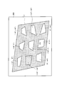
図9に示すように、水平方向調整具112の回動によって水平方向調整具112から水平方向調整信号が入力されると、投写型映像表示装置100は、水平方向における画素数を変更する。ここでは、投写型映像表示装置100は、映像の上側の行ほど、水平方向における映像の幅を減少する。例えば、投写型映像表示装置100は、水平方向における画素の間引き処理や水平方向における画素の補間処理によって、水平方向における映像の幅を制御する。図9に示すケースは、例えば、投写面300の下側から映像光を投写するケースおいて、投写面300上に適切な映像が構成される。
As shown in FIG. 9, when a horizontal direction adjustment signal is input from the horizontal direction adjustment tool 112 by the rotation of the horizontal direction adjustment tool 112, the projection display apparatus 100 changes the number of pixels in the horizontal direction. Here, the projection display apparatus 100 reduces the width of the image in the horizontal direction as the upper line of the image is increased. For example, the projection display apparatus 100 controls the width of the image in the horizontal direction by performing pixel thinning processing in the horizontal direction and pixel interpolation processing in the horizontal direction. In the case illustrated in FIG. 9, for example, in a case where image light is projected from the lower side of the projection plane 300, an appropriate image is configured on the projection plane 300.
なお、投写面300上に投写される光の幅は不変であるため、図9に示す斜線部分では、背景表示が行われる。背景表示は、例えば、白表示や黒表示である。
Note that since the width of the light projected on the projection plane 300 is unchanged, the background display is performed in the hatched portion shown in FIG. The background display is, for example, white display or black display.
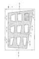
図10に示すように、垂直方向調整具113の回動によって垂直方向調整具113から垂直方向調整信号が入力されると、投写型映像表示装置100は、垂直方向における画素数を変更する。ここでは、投写型映像表示装置100は、映像の右側の列ほど、垂直方向における映像の高さを減少する。例えば、投写型映像表示装置100は、垂直方向における画素の間引き処理や垂直方向における画素の補間処理によって、垂直方向における映像の高さを制御する。図10に示すケースは、例えば、投写面300の左下側から映像光を投写するケースにおいて、投写面300上に適切な映像が構成される。
As shown in FIG. 10, when the vertical adjustment signal is input from the vertical adjustment tool 113 by the rotation of the vertical adjustment tool 113, the projection display apparatus 100 changes the number of pixels in the vertical direction. Here, the projection display apparatus 100 decreases the height of the image in the vertical direction as the right column of the image. For example, the projection display apparatus 100 controls the height of the image in the vertical direction by performing pixel thinning processing in the vertical direction and pixel interpolation processing in the vertical direction. In the case illustrated in FIG. 10, for example, in a case where image light is projected from the lower left side of the projection plane 300, an appropriate image is configured on the projection plane 300.
なお、投写面300上に投写される光の幅は不変であるため、図10に示す斜線部分では、背景表示が行われる。背景表示は、例えば、白表示や黒表示である。
Note that since the width of the light projected on the projection plane 300 is unchanged, background display is performed in the hatched portion shown in FIG. The background display is, for example, white display or black display.
(作用及び効果)
第1実施形態に係る投写型映像表示装置100では、台形補正機能に専用で用いる水平方向調整具112及び垂直方向調整具113が本体部110に設けられている。従って、持ち運び型の投写型映像表示装置100において、台形補正機能を利用するための操作が簡略化される。 (Function and effect)
In theprojection display apparatus 100 according to the first embodiment, the main body 110 is provided with a horizontal direction adjustment tool 112 and a vertical direction adjustment tool 113 that are used exclusively for the trapezoidal correction function. Therefore, the operation for using the trapezoidal correction function in the portable projection display 100 is simplified.
第1実施形態に係る投写型映像表示装置100では、台形補正機能に専用で用いる水平方向調整具112及び垂直方向調整具113が本体部110に設けられている。従って、持ち運び型の投写型映像表示装置100において、台形補正機能を利用するための操作が簡略化される。 (Function and effect)
In the
すなわち、第1実施形態では、持ち運び型の投写型映像表示装置100における台形補正機能の利用頻度の高さに着目して、台形補正機能に専用で用いる水平方向調整具112及び垂直方向調整具113が本体部110に設けられていることに留意すべきである。
That is, in the first embodiment, paying attention to the high frequency of use of the trapezoid correction function in the portable projection display apparatus 100, the horizontal direction adjustment tool 112 and the vertical direction adjustment tool 113 used exclusively for the keystone correction function. It should be noted that is provided in the main body 110.
[変更例1]
以下において、第1実施形態の変更例1について説明する。以下においては、第1実施形態との差異について主として説明する。 [Modification 1]
Hereinafter, Modification Example 1 of the first embodiment will be described. In the following, differences from the first embodiment will be mainly described.
以下において、第1実施形態の変更例1について説明する。以下においては、第1実施形態との差異について主として説明する。 [Modification 1]
Hereinafter, Modification Example 1 of the first embodiment will be described. In the following, differences from the first embodiment will be mainly described.
具体的には、変更例1では、水平方向調整具112及び垂直方向調整具113の構成例について、図11~図14を参照しながら説明する。
Specifically, in Modification 1, configuration examples of the horizontal direction adjustment tool 112 and the vertical direction adjustment tool 113 will be described with reference to FIGS.
図11に示すように、水平方向調整具112及び垂直方向調整具113は、回動可能に構成された回動部材112a及び回動部材113aを有する。このようなケースでは、水平方向調整具112及び垂直方向調整具113は、回動部材112a及び回動部材113aの回動に応じて、水平方向調整信号及び垂直方向調整信号を出力する。
As shown in FIG. 11, the horizontal direction adjustment tool 112 and the vertical direction adjustment tool 113 include a rotation member 112 a and a rotation member 113 a configured to be rotatable. In such a case, the horizontal direction adjustment tool 112 and the vertical direction adjustment tool 113 output a horizontal direction adjustment signal and a vertical direction adjustment signal according to the rotation of the rotation member 112a and the rotation member 113a.
図12に示すように、水平方向調整具112及び垂直方向調整具113は、回動可能に構成された回動部材112b及び回動部材113bを有する。このようなケースでは、水平方向調整具112及び垂直方向調整具113は、回動部材112b及び回動部材113bの回動に応じて、水平方向調整信号及び垂直方向調整信号を出力する。
As shown in FIG. 12, the horizontal direction adjustment tool 112 and the vertical direction adjustment tool 113 have a rotation member 112b and a rotation member 113b that are configured to be rotatable. In such a case, the horizontal direction adjustment tool 112 and the vertical direction adjustment tool 113 output a horizontal direction adjustment signal and a vertical direction adjustment signal in accordance with the rotation of the rotation member 112b and the rotation member 113b.
なお、図12に示す回動部材112b及び回動部材113bの回動軸の向きは、図11に示す回動部材112a及び回動部材113aの回動軸の向きと異なっている。
In addition, the directions of the rotation shafts of the rotation member 112b and the rotation member 113b shown in FIG. 12 are different from the directions of the rotation shafts of the rotation member 112a and the rotation member 113a shown in FIG.
図13に示すように、水平方向調整具112及び垂直方向調整具113は、スライド可能に構成されたスライド部材112c及びスライド部材113cを有する。このようなケースでは、水平方向調整具112及び垂直方向調整具113は、スライド部材112c及びスライド部材113cのスライドに応じて、水平方向調整信号及び垂直方向調整信号を出力する。
As shown in FIG. 13, the horizontal direction adjustment tool 112 and the vertical direction adjustment tool 113 include a slide member 112c and a slide member 113c configured to be slidable. In such a case, the horizontal direction adjustment tool 112 and the vertical direction adjustment tool 113 output a horizontal direction adjustment signal and a vertical direction adjustment signal in accordance with the slide of the slide member 112c and the slide member 113c.
図14に示すように、水平方向調整具112及び垂直方向調整具113は、押下可能に構成された操作ボタン112d、操作ボタン112e、操作ボタン113d及び操作ボタン113eを有する。このようなケースでは、水平方向調整具112及び垂直方向調整具113は、操作ボタン112d、操作ボタン112e、操作ボタン113d及び操作ボタン113eの押下に応じて、水平方向調整信号及び垂直方向調整信号を出力する。
As shown in FIG. 14, the horizontal direction adjustment tool 112 and the vertical direction adjustment tool 113 include an operation button 112d, an operation button 112e, an operation button 113d, and an operation button 113e that are configured to be pressed. In such a case, the horizontal direction adjustment tool 112 and the vertical direction adjustment tool 113 receive the horizontal direction adjustment signal and the vertical direction adjustment signal in response to pressing of the operation button 112d, the operation button 112e, the operation button 113d, and the operation button 113e. Output.
[変更例2]
以下において、第1実施形態の変更例2について説明する。以下においては、第1実施形態との差異について主として説明する。 [Modification 2]
Hereinafter, Modification Example 2 of the first embodiment will be described. In the following, differences from the first embodiment will be mainly described.
以下において、第1実施形態の変更例2について説明する。以下においては、第1実施形態との差異について主として説明する。 [Modification 2]
Hereinafter, Modification Example 2 of the first embodiment will be described. In the following, differences from the first embodiment will be mainly described.
具体的には、変更例2では、図15に示すように、投写型映像表示装置100(画像処理部151)は、水平方向調整信号及び垂直方向調整信号に応じて、映像信号の変換要求を端末200に出力する。投写型映像表示装置100は、映像信号の変換要求として、水平方向調整信号及び垂直方向調整信号を端末200に出力してもよい。
Specifically, in the second modification, as shown in FIG. 15, the projection display apparatus 100 (image processing unit 151) issues a video signal conversion request in accordance with the horizontal direction adjustment signal and the vertical direction adjustment signal. Output to the terminal 200. The projection display apparatus 100 may output a horizontal direction adjustment signal and a vertical direction adjustment signal to the terminal 200 as a video signal conversion request.
なお、端末200は、映像信号の変換要求に応じて、水平方向における画素数の変換及び垂直方向における画素数の変換を行う。端末200は、変換後の映像信号を投写型映像表示装置100(画像処理部151)に出力する。変換後の映像信号は、水平方向における画素数を変更し、垂直方向における画素数を変更する信号である。
Note that the terminal 200 converts the number of pixels in the horizontal direction and the number of pixels in the vertical direction in response to a video signal conversion request. The terminal 200 outputs the converted video signal to the projection display apparatus 100 (image processing unit 151). The converted video signal is a signal for changing the number of pixels in the horizontal direction and changing the number of pixels in the vertical direction.
[変更例3]
以下において、第1実施形態の変更例3について説明する。以下においては、第1実施形態との差異について主として説明する。 [Modification 3]
Hereinafter, Modification 3 of the first embodiment will be described. In the following, differences from the first embodiment will be mainly described.
以下において、第1実施形態の変更例3について説明する。以下においては、第1実施形態との差異について主として説明する。 [Modification 3]
Hereinafter, Modification 3 of the first embodiment will be described. In the following, differences from the first embodiment will be mainly described.
具体的には、変更例3では、映像信号の変換ではなくて、投写素子154の走査間隔の制御によって、台形補正機能を実現する。
Specifically, in the third modification, the trapezoidal correction function is realized not by converting the video signal but by controlling the scanning interval of the projection element 154.
図16に示すように、投写素子駆動部155は、投写素子154の走査方向が水平方向である場合には、水平方向調整具112から水平方向調整信号を取得する。なお、投写素子駆動部155は、投写素子154の走査方向が垂直方向である場合には、垂直方向調整具113から垂直方向調整信号を取得してもよい。
As shown in FIG. 16, the projection element driving unit 155 acquires a horizontal direction adjustment signal from the horizontal direction adjustment tool 112 when the scanning direction of the projection element 154 is the horizontal direction. Note that the projection element driving unit 155 may acquire the vertical direction adjustment signal from the vertical direction adjustment tool 113 when the scanning direction of the projection element 154 is the vertical direction.
投写素子駆動部155は、水平方向調整信号又は垂直方向調整信号に基づいて、台形補正機能を制御する。具体的には、投写素子駆動部155は、投写素子154の走査方向が水平方向である場合には、水平方向調整信号に基づいて、水平方向における投写素子154の走査間隔を制御する。なお、投写素子駆動部155は、投写素子154の走査方向が垂直方向である場合には、垂直方向調整信号に基づいて、垂直方向における投写素子154の走査間隔を制御してもよい。
The projection element driving unit 155 controls the keystone correction function based on the horizontal direction adjustment signal or the vertical direction adjustment signal. Specifically, when the scanning direction of the projection element 154 is the horizontal direction, the projection element driving unit 155 controls the scanning interval of the projection element 154 in the horizontal direction based on the horizontal direction adjustment signal. Note that, when the scanning direction of the projection element 154 is the vertical direction, the projection element driving unit 155 may control the scanning interval of the projection element 154 in the vertical direction based on the vertical direction adjustment signal.
変更例3では、投写素子154の走査方向が水平方向であるケースの制御例について説明する。
In Modification Example 3, a control example in the case where the scanning direction of the projection element 154 is the horizontal direction will be described.
第1に、映像の下側の行ほど、映像の幅を減少するケースについて、図17を参照しながら説明する。なお、垂直方向における投写素子154の駆動周波数(V)、水平方向における投写素子154の駆動周波数(H)については特に変更されない。投写素子駆動部155は、水平方向における投写素子154の入力電流値(H)を徐々に減少することによって、投写素子154に設けられたミラーの振角(H)を徐々に減少する。これによって、映像の下側の行ほど、投写素子154の走査間隔が狭まる。
First, a case where the width of the video is reduced as the lower line of the video is described with reference to FIG. The driving frequency (V) of the projection element 154 in the vertical direction and the driving frequency (H) of the projection element 154 in the horizontal direction are not particularly changed. The projection element driving unit 155 gradually decreases the swing angle (H) of the mirror provided in the projection element 154 by gradually decreasing the input current value (H) of the projection element 154 in the horizontal direction. As a result, the scanning interval of the projection element 154 becomes narrower in the lower row of the image.
第2に、映像の上側の行ほど、映像の幅を減少するケースについて、図18を参照しながら説明する。なお、垂直方向における投写素子154の駆動周波数(V)、水平方向における投写素子154の駆動周波数(H)については特に変更されない。投写素子駆動部155は、水平方向における投写素子154の入力電流値(H)を徐々に増大することによって、投写素子154に設けられたミラーの振角(H)を徐々に増大する。これによって、映像の下側の行ほど、投写素子154の走査間隔が拡がる。
Secondly, a case where the width of the video decreases as the upper line of the video is described with reference to FIG. The driving frequency (V) of the projection element 154 in the vertical direction and the driving frequency (H) of the projection element 154 in the horizontal direction are not particularly changed. The projection element driving unit 155 gradually increases the swing angle (H) of the mirror provided in the projection element 154 by gradually increasing the input current value (H) of the projection element 154 in the horizontal direction. As a result, the scanning interval of the projection element 154 increases toward the lower line of the image.
このように、投写素子154の走査方向が水平方向であるケースでは、画像処理部151は、垂直方向調整具113から入力される垂直方向調整信号に基づいて、垂直方向における画素数の変換を行うことが好ましい。
As described above, in the case where the scanning direction of the projection element 154 is the horizontal direction, the image processing unit 151 converts the number of pixels in the vertical direction based on the vertical direction adjustment signal input from the vertical direction adjustment tool 113. It is preferable.
なお、投写素子154の走査方向が垂直方向であるケースについては、投写素子154の走査方向が水平方向であるケースと同様である。従って、その説明について省略する。
It should be noted that the case where the scanning direction of the projection element 154 is the vertical direction is the same as the case where the scanning direction of the projection element 154 is the horizontal direction. Therefore, the description thereof is omitted.
[第2実施形態]
以下において、第2実施形態について、図面を参照しながら説明する。以下においては、第1実施形態との相違点について主として説明する。 [Second Embodiment]
Hereinafter, the second embodiment will be described with reference to the drawings. In the following, differences from the first embodiment will be mainly described.
以下において、第2実施形態について、図面を参照しながら説明する。以下においては、第1実施形態との相違点について主として説明する。 [Second Embodiment]
Hereinafter, the second embodiment will be described with reference to the drawings. In the following, differences from the first embodiment will be mainly described.
第2実施形態では、投写型映像表示装置100は、投写面300上に投写される光によって構成される映像として、少なくとも2以上の補正用形状を投写面300上に構成する。補正用形状は、投写角度に応じて所定基準形状を変形させた形状である。
In the second embodiment, the projection display apparatus 100 configures at least two or more correction shapes on the projection plane 300 as an image formed by light projected on the projection plane 300. The correction shape is a shape obtained by deforming the predetermined reference shape according to the projection angle.
(表示システムの機能)
以下において、第2実施形態に係る表示システムの機能について、図面を参照しながら説明する。図19は、第2実施形態に係る表示システムの機能を示す図である。なお、図19では、図7と同様の構成について同様の符号を付していることに留意すべきである。 (Display system functions)
Hereinafter, functions of the display system according to the second embodiment will be described with reference to the drawings. FIG. 19 is a diagram illustrating functions of the display system according to the second embodiment. In FIG. 19, it should be noted that the same components as those in FIG.
図19に示すように、投写型映像表示装置100は、図7に示す構成に加えて、記憶部156を有する。
As shown in FIG. 19, the projection display apparatus 100 includes a storage unit 156 in addition to the configuration shown in FIG.
記憶部156は、複数の補正用形状を記憶する。具体的には、記憶部156は、図20に示すように、投写素子154が投写面300に光を投写する角度である投写角度と、投写角度に応じて所定基準形状を変形させた複数の補正用形状とを対応付けて記憶する。
The storage unit 156 stores a plurality of correction shapes. Specifically, as illustrated in FIG. 20, the storage unit 156 includes a projection angle that is an angle at which the projection element 154 projects light onto the projection plane 300, and a plurality of predetermined reference shapes deformed according to the projection angle. The correction shape is stored in association with it.
ここで、所定基準形状は、投写角度が基準投写角度である場合に、投写面300上に投写される光によって構成される光投写領域(例えば、横縦比が4:3の長方形や横縦比が16:9の長方形)の相似形状であることが好ましい。
Here, when the projection angle is the reference projection angle, the predetermined reference shape is a light projection area configured by light projected on the projection plane 300 (for example, a rectangle or a horizontal / vertical ratio with an aspect ratio of 4: 3). A similar shape having a ratio of 16: 9 rectangle) is preferable.
補正用形状は、投写角度が補正用形状と対応付けられた投写角度である場合に、投写面300上に所定基準形状が構成されるように変形された形状である。補正用形状は、投写角度が補正用形状と対応付けられた投写角度である場合に、投写面300上に投写される光によって構成される光投写領域(例えば、4:3の長方形や16:9の長方形)の相似形状であることが好ましい。
The correction shape is a shape deformed so that a predetermined reference shape is formed on the projection plane 300 when the projection angle is a projection angle associated with the correction shape. When the projection angle is a projection angle associated with the correction shape, the correction shape is a light projection area (for example, a 4: 3 rectangle or 16: Nine rectangles) are preferable.
第2実施形態では、図20に示すように、投写角度は、基準投写角度からのパン角及び基準投写角度からのチルト角によって表される。また、基準投写角度は、パン角及びチルト角の双方が0°である投写角度である。例えば、基準投写角度は、投写型映像表示装置100の光軸と投写面300の法線とが一致する投写角度である。なお、以下においては、他の補正用形状と区別するために、基準投写角度と対応付けられた補正用形状を“補正用形状STD”と称する。
In the second embodiment, as shown in FIG. 20, the projection angle is represented by the pan angle from the reference projection angle and the tilt angle from the reference projection angle. The reference projection angle is a projection angle in which both the pan angle and the tilt angle are 0 °. For example, the reference projection angle is a projection angle at which the optical axis of the projection display apparatus 100 matches the normal line of the projection plane 300. Hereinafter, in order to distinguish from other correction shapes, the correction shape associated with the reference projection angle is referred to as “correction shape STD”.
上述した画像処理部151は、投写面300上に投写される光によって構成される映像として、複数の補正用形状のうち、少なくとも2以上の補正用形状を投写面300上に構成するように、固体光源駆動部153及び投写素子駆動部155を制御する。すなわち、画像処理部151は、複数の補正用形状のうち、少なくとも2以上の補正用形状を投写面300上に構成するように、固体光源152及び投写素子154を間接的に制御する。
The image processing unit 151 described above is configured so that at least two or more correction shapes among the plurality of correction shapes are configured on the projection plane 300 as an image configured by light projected on the projection plane 300. The solid-state light source driving unit 153 and the projection element driving unit 155 are controlled. That is, the image processing unit 151 indirectly controls the solid-state light source 152 and the projection element 154 so that at least two correction shapes among the plurality of correction shapes are configured on the projection plane 300.
(補正用形状の表示例)
以下において、第2実施形態に係る補正用形状の表示例について、図面を参照しながら説明する。図21~図25は、第2実施形態に係る補正用形状の表示例を示す図である。 (Example of display of correction shape)
Hereinafter, a display example of the correction shape according to the second embodiment will be described with reference to the drawings. 21 to 25 are diagrams showing display examples of the correction shape according to the second embodiment.
図21に示すように、投写角度が基準投写角度(チルト角=0°、かつ、パン角=0°)である場合には、投写面300上において、補正用形状STDが光投写領域Tの中心に構成される。なお、投写角度が基準投写角度であるため、投写面300上において、補正用形状STDは、所定基準形状と同じ形状である。また、投写面300上において、光投写領域Tの中心に構成された中心補正用形状と対応付けられた投写角度(チルト角=0°、かつ、パン角=0°)に対して、第1間隔(例えば、チルト角=±40°及びパン角=±40°)の投写角度と対応付けられた補正用図形が中心補正用形状の周囲に構成される。
As shown in FIG. 21, when the projection angle is the reference projection angle (tilt angle = 0 ° and pan angle = 0 °), the correction shape STD is on the projection surface 300 in the light projection region T. It is composed at the center. Since the projection angle is the reference projection angle, the correction shape STD is the same shape as the predetermined reference shape on the projection plane 300. Further, on the projection plane 300, the first projection angle (tilt angle = 0 ° and pan angle = 0 °) associated with the center correction shape formed at the center of the light projection region T is the first. A correction graphic associated with the projection angles at intervals (for example, tilt angle = ± 40 ° and pan angle = ± 40 °) is formed around the center correction shape.
図22に示すように、投写角度が基準投写角度(チルト角=0°、かつ、パン角=0°)と異なる場合には、投写面300上において、補正用形状STDは、所定基準形状とは異なる形状である。
As shown in FIG. 22, when the projection angle is different from the reference projection angle (tilt angle = 0 ° and pan angle = 0 °), the correction shape STD on the projection plane 300 is a predetermined reference shape. Are different shapes.
図22に示す状態で、操作I/Fを用いて“上方向”が操作されると、図23に示すように、投写面300上において、投写面300上に構成される補正用形状の一覧がスクロールする。すなわち、投写面300上において、投写角度(チルト角=+40°、かつ、パン角=0°)と対応付けられた補正用形状が光投写領域Tの中心に構成される。また、投写面300上において、光投写領域Tの中心に構成された中心補正用形状と対応付けられた投写角度(チルト角=+40°、かつ、パン角=0°)に対して、第1間隔(例えば、チルト角=±40°及びパン角=±40°)の投写角度と対応付けられた補正用図形が中心補正用形状の周囲に構成される。
When “upward” is operated using the operation I / F in the state shown in FIG. 22, a list of correction shapes configured on the projection plane 300 on the projection plane 300 as shown in FIG. 23. Scrolls. That is, on the projection plane 300, a correction shape associated with the projection angle (tilt angle = + 40 ° and pan angle = 0 °) is formed at the center of the light projection region T. Further, on the projection surface 300, the first projection angle (tilt angle = + 40 ° and pan angle = 0 °) associated with the center correction shape formed at the center of the light projection region T is the first. A correction graphic associated with the projection angles at intervals (for example, tilt angle = ± 40 ° and pan angle = ± 40 °) is formed around the center correction shape.
なお、操作I/Fとしては、水平方向調整具112及び垂直方向調整具113を用いることができる。また、操作I/Fとしては、端末200に設けられたキー(例えば、カーソルキー)を用いてもよい。さらに、操作I/Fとしては、リモートコントローラに設けられたキー(例えば、カーソルキー)を用いてもよい。
In addition, as the operation I / F, the horizontal direction adjustment tool 112 and the vertical direction adjustment tool 113 can be used. As the operation I / F, a key (for example, a cursor key) provided on the terminal 200 may be used. Further, as the operation I / F, a key (for example, a cursor key) provided on the remote controller may be used.
図23に示す状態で、操作I/Fを用いて、投写角度(チルト角=+40°、かつ、パン角=-40°)と対応付けられた補正用形状が選択されると、図24に示すように、投写面300上において、投写角度(チルト角=+40°、かつ、パン角=-40°)と対応付けられた補正用形状が光投写領域Tの中心に構成される。また、画像処理部151は、光投写領域Tの中心に構成された中心補正用形状と対応付けられた投写角度(チルト角=+40°、かつ、パン角=-40°)に応じて、台形補正機能を制御する。これによって、光投写領域Tは、中心補正形状の相似形状に補正される。
When the correction shape associated with the projection angle (tilt angle = + 40 ° and pan angle = −40 °) is selected using the operation I / F in the state shown in FIG. 23, FIG. As shown, a correction shape associated with the projection angle (tilt angle = + 40 ° and pan angle = −40 °) is formed at the center of the light projection area T on the projection plane 300. In addition, the image processing unit 151 has a trapezoidal shape according to a projection angle (tilt angle = + 40 ° and pan angle = −40 °) associated with the center correction shape formed at the center of the light projection region T. Control the correction function. As a result, the light projection area T is corrected to a similar shape to the center correction shape.
また、投写面300上において、中心補正用形状と対応付けられた投写角度(チルト角=+40°、かつ、パン角=-40°)に対して、第2間隔(例えば、チルト角=±20°及びパン角=±20°)の投写角度と対応付けられた補正用図形が中心補正用形状の周囲に構成される。なお、第2間隔は、第1間隔よりも狭いことに留意すべきである。
On the projection plane 300, the second interval (for example, tilt angle = ± 20) with respect to the projection angle (tilt angle = + 40 ° and pan angle = −40 °) associated with the center correction shape. A correction figure associated with a projection angle of (° and pan angle = ± 20 °) is formed around the center correction shape. It should be noted that the second interval is narrower than the first interval.
図24に示す状態で、操作I/Fを用いて、投写角度(チルト角=+40°、かつ、パン角=-40°)と対応付けられた補正用形状が最終選択されると、図25に示すように、投写面300上において、投写角度(チルト角=+20°、かつ、パン角=-20°)と対応付けられた補正用形状の相似形状に光投写領域Tが補正される。すなわち、画像処理部151は、最終選択された補正用形状と対応付けられた投写角度(チルト角=+20°、かつ、パン角=-20°)に応じて、台形補正機能を制御する。
When the correction shape associated with the projection angle (tilt angle = + 40 ° and pan angle = −40 °) is finally selected using the operation I / F in the state shown in FIG. As shown in FIG. 5, on the projection plane 300, the light projection region T is corrected to a similar shape to the correction shape associated with the projection angle (tilt angle = + 20 ° and pan angle = −20 °). In other words, the image processing unit 151 controls the trapezoidal correction function according to the projection angle (tilt angle = + 20 ° and pan angle = −20 °) associated with the final selected correction shape.
(作用及び効果)
第2実施形態では、投写型映像表示装置100は、投写面300上に投写される光によって構成される映像として、投写角度に応じて所定基準形状を変形させた補正用形状を投写面300上に構成する。従って、投写面300上において、所定基準形状に類似する補正用形状を選択すればよく、映像調整(台形補正)を容易に行うことができる。 (Function and effect)
In the second embodiment, theprojection display apparatus 100 displays, on the projection plane 300, a correction shape obtained by deforming a predetermined reference shape according to the projection angle as an image composed of light projected on the projection plane 300. Configure. Therefore, a correction shape similar to the predetermined reference shape may be selected on the projection plane 300, and image adjustment (trapezoid correction) can be easily performed.
第2実施形態では、投写型映像表示装置100は、投写面300上に投写される光によって構成される映像として、投写角度に応じて所定基準形状を変形させた補正用形状を投写面300上に構成する。従って、投写面300上において、所定基準形状に類似する補正用形状を選択すればよく、映像調整(台形補正)を容易に行うことができる。 (Function and effect)
In the second embodiment, the
[第3実施形態]
以下において、第3実施形態について、図面を参照しながら説明する。以下においては、第1実施形態との相違点について主として説明する。 [Third Embodiment]
Hereinafter, a third embodiment will be described with reference to the drawings. In the following, differences from the first embodiment will be mainly described.
以下において、第3実施形態について、図面を参照しながら説明する。以下においては、第1実施形態との相違点について主として説明する。 [Third Embodiment]
Hereinafter, a third embodiment will be described with reference to the drawings. In the following, differences from the first embodiment will be mainly described.
第3実施形態では、投写型映像表示装置100は、投写型映像表示装置100を起動したときの起動映像として、映像調整機能(台形補正機能)の処理が完了した時点で垂線を構成する垂直ガイド線及び映像調整機能(台形補正機能)の処理が完了した時点で水平線を構成する水平ガイド線を投写面300上に構成する。
In the third embodiment, the projection display apparatus 100 uses a vertical guide that forms a vertical line when processing of the image adjustment function (trapezoid correction function) is completed as a startup image when the projection display apparatus 100 is started. When the processing of the line and image adjustment function (trapezoid correction function) is completed, a horizontal guide line constituting the horizontal line is configured on the projection plane 300.
(起動映像の表示例)
以下において、第3実施形態に係る起動映像の表示例について、図面を参照しながら説明する。図26及び図27は、第3実施形態に係る起動映像の表示例を示す図である。詳細には、図26は、映像調整機能(台形補正機能)の処理が完了する前の起動映像を示しており、図27は、映像調整機能(台形補正機能)の処理が完了した後の起動映像を示している。 (Example of startup video display)
Hereinafter, a display example of a start-up image according to the third embodiment will be described with reference to the drawings. FIG. 26 and FIG. 27 are diagrams illustrating display examples of the start-up video according to the third embodiment. Specifically, FIG. 26 shows a startup video before the processing of the video adjustment function (keystone correction function) is completed, and FIG. 27 shows the startup after the processing of the video adjustment function (keystone correction function) is completed. A video is shown.
図26及び図27に示すように、投写型映像表示装置100は、投写型映像表示装置100を起動したときの起動映像として、垂直ガイド線301及び水平ガイド線302を投写面300上に構成する。また、投写型映像表示装置100は、起動映像として、垂直ガイド線301及び水平ガイド線302に加えて、ロゴマーク等の初期画像303を投写面300上に構成してもよい。
As shown in FIGS. 26 and 27, the projection display apparatus 100 configures a vertical guide line 301 and a horizontal guide line 302 on the projection plane 300 as startup images when the projection display apparatus 100 is started. . In addition to the vertical guide line 301 and the horizontal guide line 302, the projection display apparatus 100 may configure an initial image 303 such as a logo mark on the projection plane 300 as a startup image.
言い換えると、上述した画像処理部151は、起動映像として、垂線ガイド線、水平ガイド線及び初期画像303を投写面300上に構成するように、固体光源駆動部153及び投写素子駆動部155を制御する。すなわち、画像処理部151は、垂線ガイド線、水平ガイド線及び初期画像303を投写面300上に構成するように、固体光源152及び投写素子154を間接的に制御する。
In other words, the above-described image processing unit 151 controls the solid-state light source driving unit 153 and the projection element driving unit 155 so that the vertical guide line, the horizontal guide line, and the initial image 303 are configured on the projection plane 300 as the startup video. To do. That is, the image processing unit 151 indirectly controls the solid-state light source 152 and the projection element 154 so that the perpendicular guide line, the horizontal guide line, and the initial image 303 are configured on the projection plane 300.
ここで、垂直ガイド線301は、映像調整機能(台形補正機能)の処理が完了した時点で垂線を構成する。また、水平ガイド線302は、映像調整機能(台形補正機能)の処理が完了した時点で水平線を構成する。
Here, the vertical guide line 301 forms a vertical line when the image adjustment function (trapezoid correction function) is completed. Further, the horizontal guide line 302 forms a horizontal line when the processing of the video adjustment function (trapezoid correction function) is completed.
従って、図26に示す起動映像では、垂直ガイド線301は、垂直になっておらず、水平ガイド線302は、水平になっていない。これに対して、図27に示す起動映像では、垂直ガイド線301は、垂直になっており、水平ガイド線302は、水平になっている。
Therefore, in the startup image shown in FIG. 26, the vertical guide line 301 is not vertical, and the horizontal guide line 302 is not horizontal. On the other hand, in the startup image shown in FIG. 27, the vertical guide line 301 is vertical, and the horizontal guide line 302 is horizontal.
なお、第3実施形態では、垂直ガイド線301及び水平ガイド線302は、それぞれ、1本である。しかしながら、実施形態は、これに限定されるものではない。垂直ガイド線301は、複数本であってもよく、水平ガイド線302は、複数本であってもよい。
In the third embodiment, each of the vertical guide line 301 and the horizontal guide line 302 is one. However, the embodiment is not limited to this. A plurality of vertical guide lines 301 may be provided, and a plurality of horizontal guide lines 302 may be provided.
また、1対の垂直ガイド線301及び1対の水平ガイド線302によって4角形が構成されてもよい。すなわち、映像調整機能(台形補正機能)の処理が完了した時点で、1対の垂直ガイド線301及び1対の水平ガイド線302は、矩形形状を構成する。
Further, a quadrangular shape may be constituted by a pair of vertical guide lines 301 and a pair of horizontal guide lines 302. That is, when the processing of the image adjustment function (trapezoid correction function) is completed, the pair of vertical guide lines 301 and the pair of horizontal guide lines 302 form a rectangular shape.
(作用及び効果)
第3実施形態では、投写型映像表示装置100は、起動映像として、垂直ガイド線301及び水平ガイド線302を投写面300上に構成する。従って、投写面300上において、垂直ガイド線301を垂直に揃え、水平ガイド線302を水平に揃えればよく、映像調整(台形補正)を容易に行うことができる。 (Function and effect)
In the third embodiment, theprojection display apparatus 100 configures a vertical guide line 301 and a horizontal guide line 302 on the projection plane 300 as a startup image. Therefore, on the projection plane 300, the vertical guide lines 301 need only be aligned vertically and the horizontal guide lines 302 need only be aligned horizontally, and image adjustment (keystone correction) can be easily performed.
第3実施形態では、投写型映像表示装置100は、起動映像として、垂直ガイド線301及び水平ガイド線302を投写面300上に構成する。従って、投写面300上において、垂直ガイド線301を垂直に揃え、水平ガイド線302を水平に揃えればよく、映像調整(台形補正)を容易に行うことができる。 (Function and effect)
In the third embodiment, the
[その他の実施形態]
本発明は上述した実施形態によって説明したが、この開示の一部をなす論述及び図面は、この発明を限定するものであると理解すべきではない。この開示から当業者には様々な代替実施形態、実施例及び運用技術が明らかとなろう。 [Other Embodiments]
Although the present invention has been described with reference to the above-described embodiments, it should not be understood that the descriptions and drawings constituting a part of this disclosure limit the present invention. From this disclosure, various alternative embodiments, examples and operational techniques will be apparent to those skilled in the art.
例えば、映像信号の変換及び走査間隔の制御を組み合わせてもよい。例えば、投写素子154の走査方向が水平方向であるケースにおいて、投写素子154の走査間隔の制御によって、水平方向における台形補正機能を実現し、映像信号の変換によって、垂直方向における台形補正機能を実現してもよい。同様に、投写素子154の走査方向が垂直方向であるケースにおいて、投写素子154の走査間隔の制御によって、垂直方向における台形補正機能を実現し、映像信号の変換によって、水平方向における台形補正機能を実現してもよい。
For example, video signal conversion and scanning interval control may be combined. For example, in the case where the scanning direction of the projection element 154 is the horizontal direction, the horizontal keystone correction function is realized by controlling the scanning interval of the projection element 154, and the vertical keystone correction function is realized by converting the video signal. May be. Similarly, in the case where the scanning direction of the projection element 154 is the vertical direction, the trapezoid correction function in the vertical direction is realized by controlling the scanning interval of the projection element 154, and the trapezoid correction function in the horizontal direction is realized by converting the video signal. It may be realized.
上述した実施形態では、持ち運び型の投写型映像表示装置100について例示した。しかしながら、投写型映像表示装置100は、据え置き型の装置であってもよい。
In the above-described embodiment, the portable projection display apparatus 100 is exemplified. However, the projection display apparatus 100 may be a stationary apparatus.
上述した実施形態では、台形補正機能の信号変換について詳述していないが、台形補正に伴って、画素数以外にも、映像信号の変換が必要であることは勿論である。
In the embodiment described above, the signal conversion of the trapezoid correction function is not described in detail, but it is needless to say that conversion of the video signal is necessary in addition to the number of pixels in accordance with the trapezoid correction.
上述した実施形態では、映像調整機能の操作に専用で用いる調整具が投写型映像表示装置100に設けられるケースについて主として説明した。しかしながら、実施形態は、これに限定されるものではない。映像調整機能の操作に用いる操作I/Fは、端末200に設けられていてもよい。端末200に設けられる操作I/Fは、映像調整機能の操作に専用で用いられなくてもよい。
In the above-described embodiment, the case where the adjustment tool used exclusively for the operation of the image adjustment function is provided in the projection display apparatus 100 has been mainly described. However, the embodiment is not limited to this. The operation I / F used for the operation of the video adjustment function may be provided in the terminal 200. The operation I / F provided in the terminal 200 may not be used exclusively for the operation of the video adjustment function.
上述した実施形態では、光源として、固体光源を例示したが、光源は、これに限定されるものではない。具体的には、光源は、UHPランプやキセノンランプであってもよい。
In the above-described embodiment, a solid light source is exemplified as the light source, but the light source is not limited to this. Specifically, the light source may be a UHP lamp or a xenon lamp.
本発明によれば、投写面上において映像を調整するための操作を簡略化することを可能とする投写型映像表示装置及び表示システムを提供することができる。
According to the present invention, it is possible to provide a projection display apparatus and a display system that can simplify an operation for adjusting an image on a projection plane.
Claims (8)
- 光源及び前記光源から出射される光を投写面上に投写する投写素子を有する本体部を備えており、
前記投写素子は、前記本体部の内部に設けられており、
前記本体部は、前記投写素子から出射される光によって構成される映像を前記投写面上において調整する映像調整機能の操作に専用で用いる調整具を有することを特徴とする投写型映像表示装置。 A main body having a light source and a projection element that projects light emitted from the light source onto a projection surface;
The projection element is provided inside the main body,
The projection-type image display apparatus, wherein the main body portion includes an adjustment tool dedicated to an operation of an image adjustment function for adjusting an image formed by light emitted from the projection element on the projection plane. - 複数軸を中心として前記本体部を回動可能に支持する支持部材と、
前記本体部及び前記支持部材を設置箇所に固定するための固定具とをさらに備えることを特徴とする請求項1に記載の投写型映像表示装置。 A support member that rotatably supports the main body around a plurality of axes;
The projection display apparatus according to claim 1, further comprising a fixing tool for fixing the main body and the support member to an installation location. - 前記調整具から入力される調整信号に基づいて、前記映像調整機能を制御する画像処理部をさらに備え、
前記投写面上に投写される映像は、水平方向に沿った行及び垂直方向に沿った列によって定まる座標を有する複数の画素によって構成されており、
前記画像処理部は、外部機器から入力される映像信号の変換によって、前記水平方向における画素数を変更し、前記垂直方向における画素数を変更することを特徴とする請求項1に記載の投写型映像表示装置。 An image processing unit for controlling the video adjustment function based on an adjustment signal input from the adjustment tool;
The image projected on the projection plane is composed of a plurality of pixels having coordinates determined by rows along the horizontal direction and columns along the vertical direction,
2. The projection type according to claim 1, wherein the image processing unit changes the number of pixels in the horizontal direction and changes the number of pixels in the vertical direction by converting a video signal input from an external device. Video display device. - 前記調整具から入力される調整信号に基づいて、前記映像調整機能を制御する画像処理部をさらに備え、
前記投写面上に投写される映像は、水平方向に沿った行及び垂直方向に沿った列によって定まる座標を有する複数の画素によって構成されており、
前記画像処理部は、映像信号の変換要求として、前記調整具から入力される調整信号を外部装置に出力し、
前記画像処理部は、変換後の映像信号を前記外部装置から取得し、
前記変換後の映像信号は、前記水平方向における画素数を変更し、前記垂直方向における画素数を変更する信号であることを特徴とする請求項1に記載の投写型映像表示装置。 An image processing unit for controlling the video adjustment function based on an adjustment signal input from the adjustment tool;
The image projected on the projection plane is composed of a plurality of pixels having coordinates determined by rows along the horizontal direction and columns along the vertical direction,
The image processing unit outputs an adjustment signal input from the adjustment tool to an external device as a video signal conversion request,
The image processing unit acquires the converted video signal from the external device,
The projection image display apparatus according to claim 1, wherein the converted video signal is a signal that changes the number of pixels in the horizontal direction and changes the number of pixels in the vertical direction. - 前記調整具から入力される調整信号に基づいて、前記映像調整機能を制御する画像処理部をさらに備え、
前記光源は、固体光源であり、
前記投写素子は、水平方向に沿った行及び垂直方向に沿った列によって定まる座標を有する複数の画素毎に前記投写面を所定走査方向に沿って走査し、
前記画像処理部は、前記所定走査方向における前記投写素子の走査間隔を制御することを特徴とする請求項1に記載の投写型映像表示装置。 An image processing unit for controlling the video adjustment function based on an adjustment signal input from the adjustment tool;
The light source is a solid light source;
The projection element scans the projection plane along a predetermined scanning direction for each of a plurality of pixels having coordinates determined by a row along a horizontal direction and a column along a vertical direction,
The projection image display apparatus according to claim 1, wherein the image processing unit controls a scanning interval of the projection element in the predetermined scanning direction. - 前記投写素子が前記投写面に光を投写する角度である投写角度と、前記投写角度に応じて所定基準形状を変形させた複数の補正用形状とを対応付けて記憶する記憶部と、
前記投写面上に投写される光によって構成される映像として、前記複数の補正用形状のうち、少なくとも2以上の補正用形状を前記投写面上に構成するように、前記光源及び前記投写素子を制御する画像処理部とをさらに備えることを特徴とする請求項1に記載の投写型映像表示装置。 A storage unit that stores a projection angle, which is an angle at which the projection element projects light onto the projection plane, and a plurality of correction shapes obtained by deforming a predetermined reference shape according to the projection angle in association with each other;
The light source and the projection element are arranged such that at least two or more correction shapes among the plurality of correction shapes are formed on the projection surface as an image formed by light projected on the projection surface. The projection display apparatus according to claim 1, further comprising an image processing unit to be controlled. - 前記投写面上に投写される光によって映像を構成するように、前記光源及び前記投写素子を制御する画像処理部をさらに備え、
前記画像処理部は、投写型映像表示装置を起動したときの起動映像として、前記映像調整機能の処理が完了した時点で垂線を構成する垂直ガイド線及び前記映像調整機能の処理が完了した時点で水平線を構成する水平ガイド線を前記投写面上に構成するように、前記光源及び前記投写素子を制御することを特徴とする請求項1に記載の投写型映像表示装置。 An image processing unit for controlling the light source and the projection element so as to form an image by light projected on the projection plane;
The image processing unit, as a start-up image when starting up the projection display apparatus, when the processing of the video adjustment function is completed, the vertical guide line constituting the perpendicular and the processing of the video adjustment function are completed 2. The projection display apparatus according to claim 1, wherein the light source and the projection element are controlled so that a horizontal guide line constituting a horizontal line is formed on the projection plane. - 光源及び前記光源から出射される光を投写面上に投写する投写素子を有する投写型映像表示装置を少なくとも備えた表示システムであって、
前記投写素子から出射される光によって構成される映像を前記投写面上において調整する映像調整機能の操作に用いる調整具を備えており、
前記投写素子は、前記投写型映像表示装置の内部に設けられることを特徴とする表示システム。 A display system comprising at least a projection-type image display device having a light source and a projection element that projects light emitted from the light source onto a projection plane,
An adjustment tool used for an operation of an image adjustment function for adjusting an image formed by light emitted from the projection element on the projection plane;
The display system, wherein the projection element is provided inside the projection display apparatus.
Priority Applications (1)
| Application Number | Priority Date | Filing Date | Title |
|---|---|---|---|
| US13/051,381 US20110279456A1 (en) | 2008-09-19 | 2011-03-18 | Projection display apparatus and display system |
Applications Claiming Priority (4)
| Application Number | Priority Date | Filing Date | Title |
|---|---|---|---|
| JP2008-241525 | 2008-09-19 | ||
| JP2008241525 | 2008-09-19 | ||
| JP2009-210255 | 2009-09-11 | ||
| JP2009210255A JP2010098728A (en) | 2008-09-19 | 2009-09-11 | Projection type video display, and display system |
Related Child Applications (1)
| Application Number | Title | Priority Date | Filing Date |
|---|---|---|---|
| US13/051,381 Continuation US20110279456A1 (en) | 2008-09-19 | 2011-03-18 | Projection display apparatus and display system |
Publications (1)
| Publication Number | Publication Date |
|---|---|
| WO2010032831A1 true WO2010032831A1 (en) | 2010-03-25 |
Family
ID=42039652
Family Applications (1)
| Application Number | Title | Priority Date | Filing Date |
|---|---|---|---|
| PCT/JP2009/066388 WO2010032831A1 (en) | 2008-09-19 | 2009-09-18 | Projection type video image display device and display system |
Country Status (3)
| Country | Link |
|---|---|
| US (1) | US20110279456A1 (en) |
| JP (1) | JP2010098728A (en) |
| WO (1) | WO2010032831A1 (en) |
Families Citing this family (17)
| Publication number | Priority date | Publication date | Assignee | Title |
|---|---|---|---|---|
| US9769354B2 (en) | 2005-03-24 | 2017-09-19 | Kofax, Inc. | Systems and methods of processing scanned data |
| US9576272B2 (en) | 2009-02-10 | 2017-02-21 | Kofax, Inc. | Systems, methods and computer program products for determining document validity |
| US9767354B2 (en) | 2009-02-10 | 2017-09-19 | Kofax, Inc. | Global geographic information retrieval, validation, and normalization |
| JP5671901B2 (en) * | 2010-09-15 | 2015-02-18 | セイコーエプソン株式会社 | Projection type display device and control method thereof |
| US8855375B2 (en) | 2012-01-12 | 2014-10-07 | Kofax, Inc. | Systems and methods for mobile image capture and processing |
| US10146795B2 (en) | 2012-01-12 | 2018-12-04 | Kofax, Inc. | Systems and methods for mobile image capture and processing |
| US9355312B2 (en) | 2013-03-13 | 2016-05-31 | Kofax, Inc. | Systems and methods for classifying objects in digital images captured using mobile devices |
| US9208536B2 (en) * | 2013-09-27 | 2015-12-08 | Kofax, Inc. | Systems and methods for three dimensional geometric reconstruction of captured image data |
| US20140316841A1 (en) | 2013-04-23 | 2014-10-23 | Kofax, Inc. | Location-based workflows and services |
| DE202014011407U1 (en) | 2013-05-03 | 2020-04-20 | Kofax, Inc. | Systems for recognizing and classifying objects in videos captured by mobile devices |
| US9386235B2 (en) | 2013-11-15 | 2016-07-05 | Kofax, Inc. | Systems and methods for generating composite images of long documents using mobile video data |
| US9760788B2 (en) | 2014-10-30 | 2017-09-12 | Kofax, Inc. | Mobile document detection and orientation based on reference object characteristics |
| US10242285B2 (en) | 2015-07-20 | 2019-03-26 | Kofax, Inc. | Iterative recognition-guided thresholding and data extraction |
| US10467465B2 (en) | 2015-07-20 | 2019-11-05 | Kofax, Inc. | Range and/or polarity-based thresholding for improved data extraction |
| US9779296B1 (en) | 2016-04-01 | 2017-10-03 | Kofax, Inc. | Content-based detection and three dimensional geometric reconstruction of objects in image and video data |
| US11062176B2 (en) | 2017-11-30 | 2021-07-13 | Kofax, Inc. | Object detection and image cropping using a multi-detector approach |
| WO2021131862A1 (en) * | 2019-12-27 | 2021-07-01 | ソニーグループ株式会社 | Information processing device, method, and program |
Citations (6)
| Publication number | Priority date | Publication date | Assignee | Title |
|---|---|---|---|---|
| JP2001069433A (en) * | 1999-08-25 | 2001-03-16 | Ricoh Co Ltd | Image projector, image projection method, and computer- readable recording medium recording program to allow computer to execute the method |
| JP2002158897A (en) * | 2000-11-17 | 2002-05-31 | Sharp Corp | Video camera |
| JP2003153133A (en) * | 2001-07-30 | 2003-05-23 | Sony Corp | Projector and image correcting method |
| JP2005033686A (en) * | 2003-07-11 | 2005-02-03 | Casio Comput Co Ltd | Trapezoidal distortion correction method and projector |
| JP2006313259A (en) * | 2005-05-09 | 2006-11-16 | Seiko Epson Corp | Supply of image to projector |
| WO2007001680A1 (en) * | 2005-06-24 | 2007-01-04 | Symbol Technologies, Inc. | Correcting for image distortion in image projectors |
Family Cites Families (18)
| Publication number | Priority date | Publication date | Assignee | Title |
|---|---|---|---|---|
| JPH05276227A (en) * | 1992-03-27 | 1993-10-22 | Daini Denden Kk | Ring-back tone volume setting system in terminal equipment |
| DE69432093T2 (en) * | 1993-09-27 | 2003-07-17 | Canon Kk | Image processing device |
| JP3667025B2 (en) * | 1997-02-28 | 2005-07-06 | キヤノン株式会社 | Resolution conversion module, printer driver incorporating the module, and image resolution conversion method thereof |
| US6877863B2 (en) * | 2002-06-12 | 2005-04-12 | Silicon Optix Inc. | Automatic keystone correction system and method |
| AU2003278708A1 (en) * | 2002-08-12 | 2004-02-25 | Walker Digital, Llc | Digital picture frame and method for editing related applications |
| JP3711973B2 (en) * | 2002-10-09 | 2005-11-02 | 株式会社日立製作所 | Projection display |
| JP4037816B2 (en) * | 2003-10-06 | 2008-01-23 | Necディスプレイソリューションズ株式会社 | Projector and method of projecting screen by projector |
| JP2005210418A (en) * | 2004-01-22 | 2005-08-04 | Sanyo Electric Co Ltd | Image processing device, method, and program |
| JP2005223393A (en) * | 2004-02-03 | 2005-08-18 | Casio Comput Co Ltd | Projector, projecting method, and projection program |
| JP4617960B2 (en) * | 2005-03-29 | 2011-01-26 | ブラザー工業株式会社 | Projection device |
| US8174627B2 (en) * | 2005-09-06 | 2012-05-08 | Hewlett-Packard Development Company, L.P. | Selectively masking image data |
| US20070099469A1 (en) * | 2005-11-03 | 2007-05-03 | Nite Ize, Inc. | General purpose magnetic connector |
| JP4635892B2 (en) * | 2006-02-09 | 2011-02-23 | セイコーエプソン株式会社 | Projection system, projector, image processing program, and recording medium on which image processing program is recorded |
| KR101225063B1 (en) * | 2006-04-04 | 2013-01-24 | 삼성전자주식회사 | Unobtrusive calibration method for projected image compensation and apparatus for the same |
| JP3129976U (en) * | 2006-12-26 | 2007-03-08 | 株式会社島津製作所 | X-ray fluoroscopic equipment |
| US20090153749A1 (en) * | 2007-12-14 | 2009-06-18 | Stephen Randall Mixon | Portable projector background color correction scheme |
| US8591039B2 (en) * | 2008-10-28 | 2013-11-26 | Smart Technologies Ulc | Image projection methods and interactive input/projection systems employing the same |
| JP5401940B2 (en) * | 2008-11-17 | 2014-01-29 | セイコーエプソン株式会社 | Projection optical system zoom ratio measurement method, projection image correction method using the zoom ratio measurement method, and projector for executing the correction method |
-
2009
- 2009-09-11 JP JP2009210255A patent/JP2010098728A/en active Pending
- 2009-09-18 WO PCT/JP2009/066388 patent/WO2010032831A1/en active Application Filing
-
2011
- 2011-03-18 US US13/051,381 patent/US20110279456A1/en not_active Abandoned
Patent Citations (6)
| Publication number | Priority date | Publication date | Assignee | Title |
|---|---|---|---|---|
| JP2001069433A (en) * | 1999-08-25 | 2001-03-16 | Ricoh Co Ltd | Image projector, image projection method, and computer- readable recording medium recording program to allow computer to execute the method |
| JP2002158897A (en) * | 2000-11-17 | 2002-05-31 | Sharp Corp | Video camera |
| JP2003153133A (en) * | 2001-07-30 | 2003-05-23 | Sony Corp | Projector and image correcting method |
| JP2005033686A (en) * | 2003-07-11 | 2005-02-03 | Casio Comput Co Ltd | Trapezoidal distortion correction method and projector |
| JP2006313259A (en) * | 2005-05-09 | 2006-11-16 | Seiko Epson Corp | Supply of image to projector |
| WO2007001680A1 (en) * | 2005-06-24 | 2007-01-04 | Symbol Technologies, Inc. | Correcting for image distortion in image projectors |
Also Published As
| Publication number | Publication date |
|---|---|
| US20110279456A1 (en) | 2011-11-17 |
| JP2010098728A (en) | 2010-04-30 |
Similar Documents
| Publication | Publication Date | Title |
|---|---|---|
| WO2010032831A1 (en) | Projection type video image display device and display system | |
| JP6164820B2 (en) | Projector, control method therefor, and image projection system | |
| US9554105B2 (en) | Projection type image display apparatus and control method therefor | |
| US10431131B2 (en) | Projector and control method for projector | |
| JP6364899B2 (en) | Projector, projector control method, and program | |
| JP6205777B2 (en) | Projection apparatus, projection method, and program for projection | |
| US9811876B2 (en) | Display apparatus and control method | |
| JP2012108479A (en) | Projection type display device and control method thereof | |
| JP2006165949A (en) | Projector system and projector | |
| JP6707871B2 (en) | Image quality correction method and image projection system | |
| US9568812B2 (en) | Image projection apparatus and control method thereof | |
| JP2017085446A (en) | Projection device, projection method and projection system | |
| JP5217194B2 (en) | projector | |
| US10847121B2 (en) | Display apparatus and method for controlling display apparatus displaying image with superimposed mask | |
| JP6665543B2 (en) | Projector and method of correcting captured image | |
| JP2008112035A (en) | Projector | |
| JP2003198995A (en) | Projector type display | |
| JP2012070031A (en) | Image display system, imaging apparatus, image display system control method, and imaging apparatus control method | |
| JP6345316B2 (en) | Projector, control method therefor, program, and storage medium | |
| JP6700955B2 (en) | Projection apparatus and projection method | |
| US11132768B2 (en) | Method for controlling display device, display device, and display system | |
| JP2019047355A (en) | projector | |
| US20220368871A1 (en) | Display apparatus, its control method, and storage medium | |
| JP2017092708A (en) | Projection apparatus, projection method, and projection system | |
| JP2021105642A (en) | Control method for display system and display system |
Legal Events
| Date | Code | Title | Description |
|---|---|---|---|
| 121 | Ep: the epo has been informed by wipo that ep was designated in this application |
Ref document number: 09814675 Country of ref document: EP Kind code of ref document: A1 |
|
| NENP | Non-entry into the national phase |
Ref country code: DE |
|
| 122 | Ep: pct application non-entry in european phase |
Ref document number: 09814675 Country of ref document: EP Kind code of ref document: A1 |