JP6164820B2 - Projector, control method therefor, and image projection system - Google Patents
Projector, control method therefor, and image projection system Download PDFInfo
- Publication number
- JP6164820B2 JP6164820B2 JP2012225969A JP2012225969A JP6164820B2 JP 6164820 B2 JP6164820 B2 JP 6164820B2 JP 2012225969 A JP2012225969 A JP 2012225969A JP 2012225969 A JP2012225969 A JP 2012225969A JP 6164820 B2 JP6164820 B2 JP 6164820B2
- Authority
- JP
- Japan
- Prior art keywords
- deformation
- image
- projector
- setting
- projection
- Prior art date
- Legal status (The legal status is an assumption and is not a legal conclusion. Google has not performed a legal analysis and makes no representation as to the accuracy of the status listed.)
- Active
Links
Images


Classifications
-
- H—ELECTRICITY
- H04—ELECTRIC COMMUNICATION TECHNIQUE
- H04N—PICTORIAL COMMUNICATION, e.g. TELEVISION
- H04N9/00—Details of colour television systems
- H04N9/12—Picture reproducers
- H04N9/31—Projection devices for colour picture display, e.g. using electronic spatial light modulators [ESLM]
- H04N9/3179—Video signal processing therefor
- H04N9/3185—Geometric adjustment, e.g. keystone or convergence
-
- H—ELECTRICITY
- H04—ELECTRIC COMMUNICATION TECHNIQUE
- H04N—PICTORIAL COMMUNICATION, e.g. TELEVISION
- H04N9/00—Details of colour television systems
- H04N9/12—Picture reproducers
- H04N9/31—Projection devices for colour picture display, e.g. using electronic spatial light modulators [ESLM]
- H04N9/3141—Constructional details thereof
- H04N9/3147—Multi-projection systems
-
- H—ELECTRICITY
- H04—ELECTRIC COMMUNICATION TECHNIQUE
- H04N—PICTORIAL COMMUNICATION, e.g. TELEVISION
- H04N9/00—Details of colour television systems
- H04N9/12—Picture reproducers
- H04N9/31—Projection devices for colour picture display, e.g. using electronic spatial light modulators [ESLM]
- H04N9/3179—Video signal processing therefor
- H04N9/3182—Colour adjustment, e.g. white balance, shading or gamut
Description
本発明は、プロジェクタ、その制御方法、及び画像投影システムに関する。 The present invention relates to a projector, a control method thereof, and an image projection system.
従来、プロジェクタ(投影装置)として、液晶パネル等のライトバルブにより生成された画像をスクリーンに投影表示するプロジェクタが知られている。また、近年、画像の高解像度化が進んでおり、例えば4K2Kや8K4K等の多画素数の画像を大画面表示することが望まれている。一般的に、プロジェクタの多画素化、大画面化のためには、液晶パネル等のライトバルブの微細化や、高輝度光源の採用が必要になり、コストが上がってしまう。そのため、通常のライトバルブや光源を有する安価なプロジェクタを複数用いたマルチ投影により、多画素、大画面の投影表示を行なうことも多い。 Conventionally, as a projector (projection device), a projector that projects and displays an image generated by a light valve such as a liquid crystal panel on a screen is known. In recent years, the resolution of images has been increased, and it is desired to display an image with a large number of pixels such as 4K2K or 8K4K on a large screen. In general, in order to increase the number of pixels of a projector and increase the screen, it is necessary to miniaturize a light valve such as a liquid crystal panel and to use a high-intensity light source, which increases costs. For this reason, a multi-pixel, large-screen projection display is often performed by multi-projection using a plurality of inexpensive projectors having ordinary light valves and light sources.
マルチ投影とは、複数の投影装置による投影画像を投影面(スクリーン)上で繋ぎ合わせて、全体として一つの画像が表示されるようにする投影方法である。複数の投影画像を繋ぎ合わせる際には、厳密に位置を合わせないと繋ぎ目が視認されてしまい、投影画像の画質低下を招く。そのために、エッジブレンドと呼ばれる、繋ぎ目を目立たなくする処理が用いられる。エッジブレンド処理では、複数の投影画像同士を一部重畳させて繋ぎ合わせる。そして、重畳領域に関して減光処理を行うことにより、重畳領域と非重畳領域の照度の段差を目立たなくする。 Multi-projection is a projection method in which projection images from a plurality of projection apparatuses are connected on a projection plane (screen) so that one image is displayed as a whole. When connecting a plurality of projection images, if the positions are not precisely aligned, the joints are visually recognized, and the image quality of the projection images is degraded. For this purpose, a process called edge blending that makes the joints inconspicuous is used. In the edge blend process, a plurality of projection images are partially overlapped and connected. Then, by performing the dimming process on the overlapping region, the difference in illuminance between the overlapping region and the non-overlapping region is made inconspicuous.
一方、設置場所の制約から、スクリーンに対し正面にプロジェクタを設置することができない場合がある。この場合、スクリーンに対するプロジェクタ本体の相対的な傾きが原因で、スクリーン上の投影画像に台形歪と呼ばれる幾何学歪が発生することがある。この台形歪を画像処理で補正する台形補正機能を有するプロジェクタがある。例えば、特許文献1に、1台のプロジェクタ本体とスクリーンとの相対的な傾斜角に基づく台形補正(キーストーン補正)の計算方法が詳細に記載されている。
On the other hand, there are cases where the projector cannot be installed in front of the screen due to restrictions on the installation location. In this case, geometric distortion called trapezoidal distortion may occur in the projected image on the screen due to the relative inclination of the projector body with respect to the screen. There is a projector having a trapezoidal correction function for correcting this trapezoidal distortion by image processing. For example,
マルチ投影を行う場合には、台形補正と重畳領域の正確な位置合わせとを両立させる必要があり、本体設置及び補正設定の作業が煩雑になる。レンズシフト機能を有しないプロジェクタでは、重畳領域の位置合わせのためにプロジェクタ本体を移動させる必要があるが、それによりプロジェクタとスクリーンの相対位置が変わってしまうため、台形補正を再設定する必要が生じる。そのため、本体の位置合わせと台形補正とを繰り返す必要がある。 When performing multi-projection, it is necessary to achieve both trapezoidal correction and accurate alignment of the overlapping region, which complicates the operations of main body installation and correction setting. In projectors that do not have a lens shift function, it is necessary to move the projector body to align the overlap area, but this changes the relative position of the projector and the screen, so that it is necessary to reset keystone correction. . Therefore, it is necessary to repeat the alignment of the main body and the keystone correction.
特許文献2には、マルチ投影時に各プロジェクタの投影画像の4隅をスクリーンの端部に位置合わせする事で台形補正を行い、各プロジェクタの重畳領域に表示したガイドを重ね合わせる事で重畳領域の位置合わせを行う方法が提案されている。 In Patent Document 2, trapezoidal correction is performed by aligning the four corners of the projected image of each projector with the edge of the screen during multi-projection, and the guide displayed on the superimposed area of each projector is overlaid. A method of aligning has been proposed.
しかしながら、通常、投影領域は重畳領域よりはるかに大きいので、投影領域の4隅の位置を調整しても、重畳領域が厳密に合致することは少ない。その場合は、それぞれのプ
ロジェクタの4隅を微調整して厳密に合わせる必要があり、手順が煩雑になるという課題がある。
However, since the projection area is usually much larger than the superposition area, the superposition area rarely exactly matches even if the positions of the four corners of the projection area are adjusted. In such a case, it is necessary to finely adjust the four corners of each projector so as to be precisely matched, and there is a problem that the procedure becomes complicated.
そこで、本発明は、複数の投影装置を用いてマルチ投影を行う場合に、重畳領域の位置合わせとキーストーン補正の設定を簡単に行うことを可能にすることを目的とする。 Therefore, an object of the present invention is to make it possible to easily perform the alignment of the overlapping region and the setting of the keystone correction when performing multi-projection using a plurality of projection apparatuses.
本発明の第1態様は、複数のプロジェクタにより投影される複数の投影画像の一部を重畳させてスクリーン上でつなぎ合わせることで1つの画像を投影する画像投影システムを構成するプロジェクタであって、
投影する画像に対して幾何学的な変形を行う変形手段と、
前記変形手段による変形処理のパラメータを設定する設定手段と、
他のプロジェクタが投影する投影画像の一部と重畳させる重畳領域の4つの頂点を識別可能に投影している状態で、前記4つの頂点のうちのいずれかを選択し、選択されている頂点の位置を移動させる指示を入力するユーザ操作を受け付ける受け付け手段と、
を備え、
前記設定手段は、前記受け付け手段により選択された頂点の位置の移動に応じて、前記変形手段により投影する画像全体の変形を行うためのパラメータを設定するものであって、前記頂点の移動を行う前の前記4つの頂点の座標と移動を行った後の前記4つの頂点の座標との関係に基づいて前記変形処理のパラメータを設定し、
前記変形手段は設定されたパラメータに基づき変形を実行するプロジェクタである。
A first aspect of the present invention is a projector that constitutes an image projection system that projects one image by superimposing a part of a plurality of projection images projected by a plurality of projectors and connecting them on a screen.
Deformation means for performing geometric deformation on the projected image;
Setting means for setting parameters for deformation processing by the deformation means;
In a state where the four vertices of the overlapping region to be overlapped with a part of the projection image projected by another projector are identifiably projected, one of the four vertices is selected, and the selected vertex Receiving means for receiving a user operation for inputting an instruction to move the position;
With
The setting means sets parameters for performing deformation of the entire image projected by the deformation means according to movement of the position of the vertex selected by the receiving means, and moves the vertex. Based on the relationship between the coordinates of the previous four vertices and the coordinates of the four vertices after the movement, the parameters of the deformation process are set,
The deformation means is a projector that performs deformation based on set parameters .
本発明の第2態様は、複数のプロジェクタにより投影される複数の投影画像の一部を重畳させてスクリーン上でつなぎ合わせることで1つの画像を投影する画像投影システムを
構成するプロジェクタの制御方法であって、
投影する画像に対して幾何学的な変形を行う変形工程と、
前記変形工程による変形処理のパラメータを設定する設定工程と、
他のプロジェクタが投影する投影画像の一部と重畳させる重畳領域の4つの頂点を識別可能に投影している状態で、前記4つの頂点のうちのいずれかを選択し、選択されている頂点の位置を移動させる指示を入力するユーザ操作を受け付ける受け付け工程と、
を有し、
前記設定工程では、前記受け付け工程において選択された頂点の位置の移動に応じて、前記変形工程において投影する画像全体の変形を行うためのパラメータが設定されるものであって、前記頂点の移動を行う前の前記4つの頂点の座標と移動を行った後の前記4つの頂点の座標との関係に基づいて前記変形処理のパラメータが設定され、
前記変形工程では、設定されたパラメータに基づき変形が実行されるプロジェクタの制御方法である。
A second aspect of the present invention is a projector control method that constitutes an image projection system that projects one image by superimposing a part of a plurality of projection images projected by a plurality of projectors and connecting them on a screen. There,
A deformation process for performing geometric deformation on the projected image;
A setting step for setting parameters for deformation processing by the deformation step;
In a state where the four vertices of the overlapping region to be overlapped with a part of the projection image projected by another projector are identifiably projected, one of the four vertices is selected, and the selected vertex An accepting step of accepting a user operation for inputting an instruction to move the position;
Have
In the setting step, a parameter for performing deformation of the entire image to be projected in the deformation step is set according to the movement of the position of the vertex selected in the receiving step, and the movement of the vertex is performed. Parameters for the deformation process are set based on the relationship between the coordinates of the four vertices before the movement and the coordinates of the four vertices after the movement,
Wherein in deforming step is a control method of a projector deformation Ru is performed based on the set parameters.
本発明の第3態様は、複数のプロジェクタにより投影される複数の投影画像の一部を重畳させてスクリーン上でつなぎ合わせることで1つの画像を投影する画像投影システムであって、
複数のプロジェクタは、基準となる基準プロジェクタと、基準プロジェクタに合わせて投影画像の位置を合わせる従属プロジェクタと、からなり、
基準プロジェクタは、
投影する画像に対して幾何学的な変形を行う変形手段と、
前記変形手段による変形処理のパラメータを設定する設定手段と、
従属プロジェクタが投影する投影画像の一部と重畳させる重畳領域の4つの頂点を識別可能に投影する投影手段と、
を備え、
前記設定手段は、自プロジェクタとスクリーンとの相対的な傾斜角に基づいて前記変形処理のパラメータを設定する第1の設定モードと、前記変形手段による変形を行う前の投影画像の位置と変形を行った後の投影画像の位置との関係に基づいて前記変形処理のパラメータを設定する第2の設定モードと、のいずれかを選択して前記変形処理のパラメータを設定し、
従属プロジェクタは、
投影する画像に対して幾何学的な変形を行う変形手段と、
前記変形手段による変形処理のパラメータを設定する設定手段と、
基準プロジェクタが投影する投影画像の一部と重畳させる重畳領域の4つの頂点を識別可能に投影している状態で、前記4つの頂点のうちのいずれかを選択し、選択されている頂点の位置を移動させる指示を入力するユーザ操作を受け付ける受け付け手段と、
を備え、
前記設定手段は、前記受け付け手段により選択された頂点の位置の移動に応じて、前記変形手段により投影する画像全体の変形を行うためのパラメータを設定するものであって、前記頂点の移動を行う前の前記4つの頂点の座標と移動を行った後の前記4つの頂点の座標との関係に基づいて前記変形処理のパラメータを設定し、前記変形手段は設定されたパラメータに基づき変形を実行する画像投影システムである。
本発明の第4態様は、複数のプロジェクタにより投影される複数の投影画像の一部を重畳させてスクリーン上でつなぎ合わせることで1つの画像を投影する画像投影システムの制御方法であって、
複数のプロジェクタは、基準となる基準プロジェクタと、基準プロジェクタに合わせて投影画像の位置を合わせる従属プロジェクタと、からなり、
基準プロジェクタが投影する画像に対して幾何学的な変形を行う第1の変形工程と、
前記第1の変形工程における変形処理のパラメータを設定する第1の設定工程と、
従属プロジェクタが投影する投影画像の一部と重畳させる重畳領域の4つの頂点を基準プロジェクタが識別可能に投影する投影工程と、
従属プロジェクタが投影する画像に対して幾何学的な変形を行う第2の変形工程と、
前記第2の変形工程における変形処理のパラメータを設定する第2の設定工程と、
基準プロジェクタが投影する投影画像の一部と重畳させる重畳領域の4つの頂点を識別可能に投影している状態で、前記4つの頂点のうちのいずれかが選択され、選択されている頂点の位置を移動させる指示を入力するユーザ操作が従属プロジェクタに受け付けられる受け付け工程と、
を有し、
前記第1の設定工程では、基準プロジェクタとスクリーンとの相対的な傾斜角に基づいて前記変形処理のパラメータを設定する第1の設定モードと、前記第1の変形工程における変形を行う前の投影画像の位置と変形を行った後の投影画像の位置との関係に基づいて前記変形処理のパラメータを設定する第2の設定モードと、のいずれかが選択されて前記変形処理のパラメータが設定され、
前記第2の設定工程では、前記受け付け工程において選択された頂点の位置の移動に応じて、前記第2の変形工程において投影する画像全体の変形を行うためのパラメータが設定されるものであって、前記頂点の移動を行う前の前記4つの頂点の座標と移動を行った後の前記4つの頂点の座標との関係に基づいて前記変形処理のパラメータが設定され、前記第2の変形工程では設定されたパラメータに基づき変形が実行される画像投影システムの制御方法である。
A third aspect of the present invention is an image projection system that projects one image by superimposing a part of a plurality of projection images projected by a plurality of projectors and connecting them on a screen.
The plurality of projectors includes a reference projector serving as a reference, and a subordinate projector that adjusts the position of the projection image according to the reference projector.
The reference projector is
Deformation means for performing geometric deformation on the projected image;
Setting means for setting parameters for deformation processing by the deformation means;
Projecting means for projectably identifying the four vertices of the superimposed region to be superimposed on a part of the projection image projected by the subordinate projector;
With
The setting means includes a first setting mode for setting parameters of the deformation processing based on a relative inclination angle between the projector and the screen, and a position and deformation of a projection image before the deformation by the deformation means. A second setting mode for setting parameters for the deformation process based on the relationship with the position of the projected image after the setting, and setting the parameters for the deformation process by selecting any one of them,
Subordinate projectors
Deformation means for performing geometric deformation on the projected image;
Setting means for setting parameters for deformation processing by the deformation means;
In a state where the four vertices of the overlapping area to be superimposed on a part of the projection image projected by the reference projector are identifiably projected, any one of the four vertices is selected, and the position of the selected vertex Receiving means for receiving a user operation to input an instruction to move
With
The setting means sets parameters for performing deformation of the entire image projected by the deformation means according to movement of the position of the vertex selected by the receiving means, and moves the vertex. The deformation processing parameters are set based on the relationship between the coordinates of the previous four vertices and the coordinates of the four vertices after the movement, and the deformation means performs the deformation based on the set parameters. An image projection system.
A fourth aspect of the present invention is a control method for an image projection system that projects one image by superimposing a part of a plurality of projection images projected by a plurality of projectors and connecting them on a screen.
The plurality of projectors includes a reference projector serving as a reference, and a subordinate projector that adjusts the position of the projection image according to the reference projector.
A first deformation step for performing geometric deformation on the image projected by the reference projector;
A first setting step for setting parameters for deformation processing in the first deformation step;
A projecting step in which the reference projector projects the four vertices of the superimposed region to be superposed on a part of the projection image projected by the subordinate projector, and
A second deformation step for performing geometric deformation on the image projected by the subordinate projector;
A second setting step for setting parameters for deformation processing in the second deformation step;
One of the four vertices is selected in a state where the four vertices of the overlapping region to be overlapped with a part of the projection image projected by the reference projector are identifiable, and the position of the selected vertex An accepting step in which a subordinate projector accepts a user operation to input an instruction to move
Have
In the first setting step, a first setting mode for setting parameters of the deformation process based on a relative inclination angle between the reference projector and the screen, and a projection before performing the deformation in the first deformation step. One of the second setting mode for setting the deformation processing parameters based on the relationship between the position of the image and the position of the projected image after the deformation is selected, and the deformation processing parameters are set. ,
In the second setting step, parameters for performing deformation of the entire image to be projected in the second deformation step are set according to the movement of the position of the vertex selected in the receiving step. The deformation processing parameters are set based on the relationship between the coordinates of the four vertices before the movement of the vertices and the coordinates of the four vertices after the movement, and in the second deformation step, It is a control method of an image projection system in which deformation is executed based on set parameters.
本発明によれば、複数の投影装置を用いてマルチ投影を行う場合に、重畳領域の位置合
わせとキーストーン補正の設定を簡単に行うことが可能になる。
According to the present invention, when performing multi-projection using a plurality of projection apparatuses, it is possible to easily perform alignment of superimposed areas and setting of keystone correction.
以下、図面を参照して本発明の実施例を詳細に説明するが、この発明は以下の実施の形態に限定されるものではない。 Hereinafter, examples of the present invention will be described in detail with reference to the drawings. However, the present invention is not limited to the following embodiments.
(実施例1)
本実施例では、投影型表示装置の一例として、透過型液晶パネルを用いたプロジェクタについて説明する。しかし、本発明は、表示デバイスとして透過型液晶パネルを用いたプロジェクタに限らない。例えば、DLP(Digital Light Processing)、LCOS(Liquid crystal on silicon、反射型液晶)パネル等の表示デバイスを用いたものであっても
適用可能である。また、液晶プロジェクタには、単板式、3板式等が一般に知られているが、どちらの方式であっても良い。
Example 1
In this embodiment, a projector using a transmissive liquid crystal panel will be described as an example of a projection display device. However, the present invention is not limited to a projector using a transmissive liquid crystal panel as a display device. For example, a display device using a display device such as a DLP (Digital Light Processing) or LCOS (Liquid crystal on silicon, reflective liquid crystal) panel is also applicable. In addition, a single-plate type, a three-plate type, and the like are generally known as the liquid crystal projector, but either type may be used.
本実施例の液晶プロジェクタは、表示するべき画像に応じて、液晶素子の光の透過率を制御して、液晶素子を透過した光源からの光をスクリーンに投影することで、画像を投影する。 The liquid crystal projector of this embodiment projects an image by controlling the light transmittance of the liquid crystal element according to the image to be displayed and projecting light from the light source that has passed through the liquid crystal element onto the screen.
以下、このような液晶プロジェクタに本発明を適用した場合の実施例について説明する。
<全体構成>
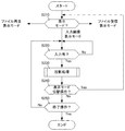
まず、図1を用いて、本実施例の液晶プロジェクタの全体構成を説明する。
図1は、本実施例の液晶プロジェクタ100の全体の構成を示す図である。
Hereinafter, an embodiment in which the present invention is applied to such a liquid crystal projector will be described.
<Overall configuration>
First, the overall configuration of the liquid crystal projector of this embodiment will be described with reference to FIG.
FIG. 1 is a diagram illustrating an overall configuration of a
本実施例の液晶プロジェクタ100は、CPU110、ROM111、RAM112、操作部113、画像入力部130、画像処理部140を有する。また、液晶プロジェクタ100は、さらに、液晶制御部150、液晶素子151R、151G、151B、光源制御部160、光源161、色分離部162、色合成部163、光学系制御部170、投影光学系171を有する。また、液晶プロジェクタ100は、さらに、記録再生部191、記録媒体192、通信部193、撮像部194、表示制御部195、表示部196を有していてもよい。
The
CPU110は、液晶プロジェクタ100の各動作ブロックを制御するものあり、RO
M111は、CPU110の処理手順を記述した制御プログラムを記憶するためのものである。また、RAM112は、ワークメモリとして一時的に制御プログラムやデータを格納するものである。また、CPU110は、記録再生部191により記録媒体192から再生された静止画像データや動画像データを一時的にRAM112に記憶し、ROM111に記憶されたプログラムを用いて、それぞれの画像や映像を再生することもできる。また、CPU110は、通信部193より受信した静止画像データや動画像データを一時的にRAM112に記憶し、ROM111に記憶されたプログラムを用いて、それぞれの画像や映像を再生したりすることもできる。また、撮像部194により得られた画像や映像を一時的にRAM112に記憶し、ROM111に記憶されたプログラムを用いて、静止画像データや動画像データに変換して記録媒体192に記録させることもできる。
The
M111 is for storing a control program describing the processing procedure of the
また、操作部113は、ユーザの指示を受け付け、CPU110に制御信号を送信するものであり、例えば、スイッチやダイヤル、表示部196上に設けられたタッチパネル等からなる。また、操作部113は、例えば、リモコンからの信号を受信する信号受信部(赤外線受信部等)で、受信した信号に基づいて所定の制御信号をCPU110に送信するものであってもよい。また、CPU110は、操作部113や、通信部193から入力された制御信号を受信して、液晶プロジェクタ100の各動作ブロックを制御する。
The
画像入力部130は、外部装置から画像信号を受信するものである。例えば、コンポジット端子、S映像端子、D端子、コンポーネント端子、アナログRGB端子、DVI−I端子、DVI−D端子、HDMI(High-Definition Multimedia Interface)(登録商標)端子等を含む。また、画像入力部130は、アナログ画像信号を受信した場合には、受信したアナログ画像信号をデジタル画像信号に変換する。そして、画像入力部130は、受信した画像信号を、画像処理部140に送信する。ここで、外部装置は、画像信号を出力できるものであれば、パーソナルコンピュータ、カメラ、携帯電話、スマートフォン、ハードディスクレコーダ、ゲーム機等、どのようなものであってもよい。
The
画像処理部140は、画像入力部130から受信した画像信号にフレーム数、画素数、画像形状等の変更処理を施して、液晶制御部150に送信するものであり、例えば画像処理用のマイクロプロセッサからなる。また、画像処理部140は、専用のマイクロプロセッサである必要はなく、例えば、ROM111に記憶されたプログラムによって、CPU110が画像処理部140と同様の処理を実行しても良い。画像処理部140は、フレーム間引き処理、フレーム補間処理、解像度変換処理、歪み補正処理(キーストーン補正処理)といった機能を実行することが可能である。また、画像処理部140は、画像入力部130から受信した画像信号以外にも、CPU110によって再生された画像や映像に対して前述の変更処理を施すこともできる。
The
液晶制御部150は、画像処理部140で処理の施された画像信号に基づいて、液晶素子151R、151G、151Bの画素の液晶に印可する電圧を制御して、液晶素子151R、151G、151Bの透過率を調整する。液晶制御部150は、制御用のマイクロプロセッサからなる。また、液晶制御部150は、専用のマイクロプロセッサである必要はなく、例えば、ROM111に記憶されたプログラムによって、CPU110が液晶制御部150と同様の処理を実行しても良い。たとえば、画像処理部140に画像信号が入力されている場合、液晶制御部150は、画像処理部140から1フレームの画像を受信する度に、画像に対応する透過率となるように、液晶素子151R、151G、151Bを制御する。液晶素子151Rは、赤色に対応する液晶素子であって、光源161から出力された光のうち、色分離部162で赤色(R)、緑色(G)、青色(B)に分離された光のうち、赤色の光の透過率を調整するためのものである。液晶素子151Gは、緑色に対応する液晶素子であって、光源161から出力された光のうち、色分離部162で赤色(R)、緑色(G)、青色(B)に分離された光のうち、緑色の光の透過率を調整するた
めのものである。液晶素子151Bは、青色に対応する液晶素子であって、光源161から出力された光のうち、色分離部162で赤色(R)、緑色(G)、青色(B)に分離された光のうち、青色の光の透過率を調整するためのものである。
The liquid
この液晶制御部150による液晶素子151R、151G、151Bの具体的な制御動作や液晶素子151R、151G、151Bの構成については、後述する。
Specific control operations of the
光源制御部160は、光源161のオン/オフの制御や光量の制御をするものであり、制御用のマイクロプロセッサからなる。また、光源制御部160は、専用のマイクロプロセッサである必要はなく、例えば、ROM111に記憶されたプログラムによって、CPU110が光源制御部160と同様の処理を実行しても良い。また、光源161は、不図示のスクリーンに画像を投影するための光を出力するものであり、例えば、ハロゲンランプ、キセノンランプ、高圧水銀ランプ等である。また、色分離部162は、光源161から出力された光を、赤色(R)、緑色(G)、青色(B)に分離するものであり、例えば、ダイクロイックミラーやプリズム等からなる。なお、光源161として、各色に対応するLED(Light Emitting Diode)等を使用する場合には、色分離部162は不要である。また、色合成部163は、液晶素子151R、151G、151Bを透過した赤色(R)、緑色(G)、青色(B)の光を合成するものであり、例えば、ダイクロイックミラーやプリズム等からなる。そして、色合成部163により赤色(R)、緑色(G)、青色(B)の成分を合成した光は、投影光学系171に送られる。このとき、液晶素子151R、151G、151Bは、画像処理部140から入力された画像に対応する光の透過率となるように、液晶制御部150により制御されている。そのため、色合成部163により合成された光が投影光学系171によりスクリーンに投影されると、画像処理部140により入力された画像に対応する画像がスクリーン上に表示されることになる。
The light
光学系制御部170は、投影光学系171を制御するものであり、制御用のマイクロプロセッサからなる。また、光学系制御部170は、専用のマイクロプロセッサである必要はなく、例えば、ROM111に記憶されたプログラムによって、CPU110が光学系制御部170と同様の処理を実行しても良い。また、投影光学系171は、色合成部163から出力された合成光をスクリーンに投影するためのものである。投影光学系171は、複数のレンズ、レンズ駆動用のアクチュエータからなり、レンズをアクチュエータにより駆動することで、投影画像の拡大、縮小、焦点調整等を行うことができる。
The optical
記録再生部191は、記録媒体192から静止画像データや動画像データを再生したり、また、撮像部194により得られた画像や映像の静止画像データや動画像データをCPU110から受信して記録媒体192に記録したりするものである。また、記録再生部191は、通信部193より受信した静止画像データや動画像データを記録媒体192に記録しても良い。記録再生部191は、例えば、記録媒体192と電気的に接続するインタフェースや記録媒体192と通信するためのマイクロプロセッサからなる。また、記録再生部191には、専用のマイクロプロセッサを含む必要はなく、例えば、ROM111に記憶されたプログラムによって、CPU110が記録再生部191と同様の処理を実行しても良い。また、記録媒体192は、静止画像データや動画像データ、その他、本実施例の液晶プロジェクタに必要な制御データ等を記録することができるものである。記録媒体192は、磁気ディスク、光学式ディスク、半導体メモリ等のあらゆる方式の記録媒体であってよく、着脱可能な記録媒体であっても、内蔵型の記録媒体であってもよい。
The recording /
通信部193は、外部機器からの制御信号や静止画像データ、動画像データ等を受信するためのものであり、例えば、無線LAN、有線LAN、USB、Bluetooth(登録商標)等であってよく、通信方式は特に限定されない。また、例えば画像入力部130の端子がHDMI(登録商標)端子であれば、その端子を介してCEC(Consumer Ele
ctronics Control)通信を行うものであっても良い。ここで、外部装置は、液晶プロジェクタ100と通信を行うことができるものであれば、パーソナルコンピュータ、カメラ、携帯電話、スマートフォン、ハードディスクレコーダ、ゲーム機、リモコン等、どのようなものであってもよい。
The
ctronics Control) Communication may be performed. Here, the external device may be any device such as a personal computer, a camera, a mobile phone, a smartphone, a hard disk recorder, a game machine, and a remote controller as long as it can communicate with the
撮像部194は、本実施例の液晶プロジェクタ100の周辺を撮像して画像信号を取得するものであり、投影光学系171を介して投影された画像を撮影(スクリーン方向を撮影)することができる。撮像部194は、得られた画像や映像をCPU110に送信し、CPU110は、その画像や映像を一時的にRAM112に記憶し、ROM111に記憶されたプログラムに基づいて、静止画像データや動画像データに変換する。撮像部194は、被写体の光学像を取得するレンズ、レンズを駆動するアクチュエータ、アクチュエータを制御するマイクロプロセッサ、光学像を画像信号に変換する撮像素子、画像信号をデジタル信号に変換するAD変換部等からなる。また、撮像部194は、スクリーン方向を撮影するものに限られず、例えば、スクリーンと逆方向の視聴者側を撮影しても良い。
The
表示制御部195は、液晶プロジェクタ100に備えられた表示部196に液晶プロジェクタ100を操作するための操作画面やスイッチアイコン等の画像を表示させるための制御をするものであり、表示制御を行うマイクロプロセッサ等からなる。また、表示制御部195専用のマイクロプロセッサである必要はなく、例えば、ROM111に記憶されたプログラムによって、CPU110が表示制御部195と同様の処理を実行しても良い。また、表示部196は、液晶プロジェクタ100を操作するための操作画面やスイッチアイコンを表示するものである。表示部196は、画像を表示できればどのようなものであっても良い。例えば、液晶ディスプレイ、CRTディスプレイ、有機ELディスプレイ、LEDディスプレイであって良い。また、特定のボタンをユーザに認識可能に掲示するために、各ボタンに対応するLED等を発光させるものであってもよい。
The
なお、本実施例の画像処理部140、液晶制御部150、光源制御部160、光学系制御部170、記録再生部191、表示制御部195は、これらの各ブロックと同様の処理を行うことのできる単数または複数のマイクロプロセッサあっても良い。または、例えば、ROM111に記憶されたプログラムによって、CPU110が各ブロックと同様の処理を実行しても良い。
Note that the
<基本動作>
次に、図1、図2を用いて、本実施例の液晶プロジェクタ100の基本動作を説明する。
図2は、本実施例の液晶プロジェクタ100の基本動作の制御を説明するためのフロー図である。図2の動作は、基本的にCPU110が、ROM111に記憶されたプログラムに基づいて、各機能ブロックを制御することにより実行されるものである。図2のフロー図は、操作部113や不図示のリモコンによりユーザが液晶プロジェクタ100の電源のオンを指示した時点をスタートとしている。
<Basic operation>
Next, the basic operation of the
FIG. 2 is a flowchart for explaining the control of the basic operation of the
操作部113や不図示のリモコンによりユーザが液晶プロジェクタ100の電源のオンを指示すると、CPU110は、不図示の電源部からプロジェクタ100の各部に不図示の電源回路から電源を供給する。
When the user instructs the
次に、CPU110は、ユーザによる操作部113やリモコンの操作により選択された表示モードを判定する(S210)。本実施例のプロジェクタ100の表示モードの一つは、画像入力部130より入力された画像を表示する「入力画像表示モード」である。また、本実施例のプロジェクタ100の表示モードの一つは、記録再生部191により記録媒体192から読み出された静止画像データや動画像データの画像や映像を表示する「フ
ァイル再生表示モード」である。また、本実施例のプロジェクタ100の表示モードの一つは、通信部193から受信した静止画像データや動画像データの画像や映像を表示する「ファイル受信表示モード」である。なお、本実施例では、ユーザにより表示モードが選択される場合について説明するが、電源を投入した時点での表示モードは、前回終了時の表示モードになっていてもよく、また、前述のいずれかの表示モードをデフォルトの表示モードとしてもよい。その場合には、S210の処理は省略可能である。
ここでは、S210で、「入力画像表示モード」が選択されたものとして説明する。
Next, the
Here, it is assumed that “input image display mode” is selected in S210.
「入力画像表示モード」が選択されると、CPU110は、画像入力部130から画像が入力されているか否かを判定する(S220)。画像が入力されていない場合(S220でNo)には、CPU110は、入力画像信号が検出されるまで待機し、画像入力されている場合(S220でYes)には、CPU110は、投影処理(S230)を実行する。
When “input image display mode” is selected,
CPU110は、投影処理として、画像入力部130より入力された画像を画像処理部140に送信し、画像処理部140に、画像の画素数、フレームレート、形状の変形を実行させ、処理の施された1画面分の画像を液晶制御部150に送信する。そして、CPU110は、液晶制御部150に、受信した1画面分の画像の赤色(R)、緑色(G)、青色(B)の各色成分の階調レベルに応じた透過率となるように、液晶素子151R、151G、151Bの透過率を制御させる。そして、CPU110は、光源制御部160に光源161からの光の出力を制御させる。色分離部162は、光源161から出力された光を、赤色(R)、緑色(G)、青色(B)に分離し、それぞれの光を、液晶素子151R、151G、151Bに供給する。液晶素子151R、151G、151Bに供給された、各色の光は、各液晶パネルの画素毎に透過する光量が制限される。そして、液晶素子151R、151G、151Bを透過した赤色(R)、緑色(G)、青色(B)それぞれの光は、色合成部163に供給され再び合成される。そして、色合成部163で合成された光は、投影光学系171を介して、不図示のスクリーンに投影される。
この投影処理は、画像を投影している間、1フレームの画像毎に順次、実行されている。
As a projection process, the
This projection processing is sequentially executed for each image of one frame while the image is projected.
ユーザにより投影光学系171の操作をする指示が操作部113から入力されると、CPU110は、光学系制御部170に、指示内容に応じて、投影画像の焦点の変更や光学系の拡大率の変更を行うように投影光学系171のアクチュエータを制御させる。
When an instruction to operate the projection
この投影処理実行中に、CPU110は、ユーザにより表示モードを切り替える指示が操作部113から入力されたか否かを判定する(S240)。ここで、ユーザにより表示モードを切り替える指示が操作部113から入力されると(S240でYes)、CPU110は、再びS210に戻り、表示モードの判定を行う。このとき、CPU110は、画像処理部140に、表示モードを選択させるためのメニュー画面をOSD(On Screen Display)画像として送信し、投影中の画像に対して、このOSD画面を重畳させるよう
に画像処理部140を制御する。ユーザは、この投影されたOSD画面を見ながら、表示モードを選択することができる。
During execution of this projection processing, the
一方、表示処理実行中に、ユーザにより表示モードを切り替える指示が操作部113から入力されない場合は(S240でNo)、CPU110は、ユーザにより投影終了の指示が操作部113から入力されたか否かを判定する(S250)。ここで、ユーザにより投影終了の指示が操作部113から入力された場合には(S250でYes)、CPU110は、プロジェクタ100の各ブロックに対する電源供給を停止させ、画像投影を終了させる。一方、ユーザにより投影終了の指示が操作部113から入力されない場合には(S250でNo)、CPU110は、S220へ戻り、以降、ユーザにより投影終了の指
示が操作部113から入力されるまでの間S220からS250までの処理を繰り返す。
以上のように、本実施例の液晶プロジェクタ100は、スクリーンに対して画像を投影する。
On the other hand, when an instruction to switch the display mode is not input from the
As described above, the
なお、「ファイル再生表示モード」では、CPU110は、記録再生部191に、記録媒体192から静止画像データや動画像データのファイルリストや各ファイルのサムネイルデータを読み出させ、RAM112に一時的に記憶する。そして、CPU110は、ROM111に記憶されたプログラムに基づいて、RAM112に一時記憶されたファイルリストに基づく文字画像や各ファイルのサムネイルデータに基づく画像を生成し、画像処理部140に送信する。そして、CPU110は、通常の投影処理(S230)と同様に、画像処理部140、液晶制御部150、光源制御部160を制御する。
In the “file playback display mode”, the
ユーザは、投影画像上に表示された、記録媒体192に記録された静止画像データや動画像データに対応する文字や画像等からなるGUIを見ながら、再生したい静止画像データや動画像データを選択する操作を操作部113を介して行う。そうすると、CPU110は、選択された静止画像データや動画像データを記録媒体192から読み出すように記録再生部191を制御する。そして、CPU110は、読み出された静止画像データや動画像データをRAM112に一時的に記憶し、ROM111記憶されたプログラムに基づいて、静止画像データや動画像データの画像や画像を再生する。
The user selects still image data or moving image data to be reproduced while viewing a GUI including characters and images corresponding to the still image data and moving image data recorded on the
そして、CPU110は、例えば再生した動画像データのフレーム毎の画像を順次、画像処理部140に送信し、通常の投影処理(S230)と同様に、画像処理部140、液晶制御部150、光源制御部160を制御する。また、静止画像データを再生した場合には、再生した画像を画像処理部140に送信し、通常の投影処理(S230)と同様に、画像処理部140、液晶制御部150、光源制御部160を制御する。
Then, the
また、「ファイル受信表示モード」では、CPU110は、通信部193から受信した静止画像データや動画像データをRAM112に一時的に記憶し、ROM111記憶されたプログラムに基づいて、静止画像データや動画像データの画像や映像を再生する。そして、CPU110は、例えば再生した動画像データのフレーム毎の画像を順次、画像処理部140に送信し、通常の投影処理(S230)と同様に、画像処理部140、液晶制御部150、光源制御部160を制御する。また、静止画像データを再生した場合には、再生した画像を画像処理部140に送信し、通常の投影処理(S230)と同様に、画像処理部140、液晶制御部150、光源制御部160を制御する。
In the “file reception display mode”, the
次に本実施例の特徴的な構成につて説明する。
図3は、図1の画像処理部140の内部構成を説明するためのブロック図である。
画像処理部140は、各種画像処理部310、OSD重畳部320、減光処理部330、変形処理部340、黒浮き処理部350を含む。
Next, a characteristic configuration of the present embodiment will be described.
FIG. 3 is a block diagram for explaining the internal configuration of the
The
元画像信号s301は、前述のように、表示モードに応じて画像入力部130、記録再生部191、通信部193等から入力される。また、タイミング信号s302は、元画像信号s301に同期した垂直同期信号、水平同期信号、クロック等のタイミング信号であって、元画像信号s301の供給元から供給される。画像処理部140内の各ブロックは、タイミング信号s302に基づいて動作するが、画像処理部140の内部でタイミング信号を作り直して使用してもよい。
As described above, the original image signal s301 is input from the
各種画像処理部310は、CPU110と連携して、元画像信号s301を入力し、各種画像処理を施して生成した画像処理信号s303をOSD重畳部320に対して出力する。各種画像処理とは、画像信号のヒストグラムやAPL(average picture level)等
の統計情報の取得処理や、IP変換、フレームレート変換、解像度変換、γ変換、色域変換、色補正、エッジ強調等の処理である。なお、これらの画像処理の詳細については公知であるので説明を割愛する。
The various
OSD重畳部320は、CPU110の指示により、ユーザ操作用のGUIを構成するメニューや操作支援のための情報を示すOSD画像を画像処理信号s303に重畳し、生成したOSD重畳信号s304を減光処理部330に対して出力する。
The
減光処理部330は、CPU110の指示により、OSD重畳部320から受信したOSD重畳信号s304に対し、エッジブレンドの減光処理を行ない、生成した重畳部減光信号s305を変形処理部340に対して出力する。減光処理部330は、減光処理として、マルチ投影の重畳領域において、非重畳領域との境界から端部に向かって徐々に減光するようなゲインをかける。
The dimming
減光処理部330の処理詳細を、図4および図5を用いて説明する。説明を簡単にするために、プロジェクタとスクリーンが正対している状態で説明する。
図4に、本実施例のマルチ投影システム(画像投影システム)の斜視図を示す。
画像信号源400は、画像ケーブル410a、410bにより、それぞれプロジェクタ420a、420bに接続され、画像信号を供給する。プロジェクタ420a、420bは、投影面であるスクリーン430に投影を行う。
Details of the processing of the
FIG. 4 is a perspective view of the multi-projection system (image projection system) of the present embodiment.
The
プロジェクタ420a、420bは、画像信号源400から送信された画像信号を、画像ケーブル410a、410bを介して受信する。プロジェクタ420a、420bは、受信した画像信号に基づく画像を一部重畳させるように投影することにより、一つの統合された大画像を投影する。このような投影方法をマルチ投影と称する。
The
図5(a)に、プロジェクタ420aの投影画像を示す。投影画像500aは、非重畳領域510a、重畳領域520aとからなる。図5(b)に、プロジェクタ420bの投影画像500bを示す。投影画像500bは、非重畳領域510b、重畳領域520bからなる。
FIG. 5A shows a projection image of the
図5(c)に示すグラフ530a,530bは、プロジェクタ420a、420bの減光処理部330がOSD重畳信号s304に適用するゲインを示す。本実施例では、非重畳領域510a,510bにおいては1.0、重畳領域520a,520bにおいては、非重畳領域との境界で1.0とし、投影画像端で0、その間では横方向の位置に応じて決まる値となるようなゲインとする。図5(c)図では、非重畳領域との境界から投影画像端までゲインが線形変化する例を示しているが、重畳領域における輝度の和が非重畳領域の輝度と同じになれば、ゲインの変化は線形変化に限らず、S字カーブ等でもよい。
図5(d)に、マルチ投影による統合後の投影画像を示す。重畳領域540は、プロジェクタ420a、420bそれぞれの重畳領域520a,520bの重ね合わせとなっており、輝度は非重畳領域510a,510bと同等であるため、境界が目立たなくなっている。
FIG. 5D shows a projection image after integration by multi-projection. The
変形処理部340は、変形の式に基づいて、重畳部減光信号s305に幾何学的な変形処理を施し、変形後画像信号s306を出力する。キーストーン補正は射影変換で実現できるため、変形処理部340は、CPU110から射影変換のためのパラメータを入力する。元画像の座標を(xs、ys)とすると、変形後画像の座標(xd、yd)は式1で表わされる。

ここで、Mは3×3行列で、CPU110から入力される元画像から変形後画像への射影変換行列である。xso、ysoは、図15に実線で示す元画像の1つの頂点の座標であり、xdo、ydoは、図15に一点鎖線で示す変形後画像の、元画像の頂点(xso、yso)に対応する頂点の座標値である。
Here, M is a 3 × 3 matrix, which is a projection transformation matrix from the original image input from the
CPU110から、式1の行列Mの逆行列M-1とオフセット(xso,yso)、(xdo,ydo)が入力され、式2に従って変形後の座標値(xd、yd)に対応する元画像の座標(xs、ys)を求める。
式2に基づいて求められた元画像の座標が整数になれば、元画像座標(xs、ys)が持つ画素値をそのまま変換後座標(xd、yd)の持つ画素値としてもよい。しかし、式2に基づいて求められた元画像の座標は整数になるとは限らないので、周辺画素の値を用いて補間することで、変形後座標(xd、yd)の持つ画素値を求める。補間の方法は、バイリニア、バイキュービック、その他の任意の補間方法を用いればよい。また、式2に基づいて求められた元画像の座標が、元画像領域の範囲外である場合には、その画素値は黒またはユーザが設定した背景色とする。
変形処理部340は、このようにして変換後座標の全てについて画素値を求め、変換後画像を作成する。
If the coordinates of the original image obtained based on Equation 2 are integers, the pixel values of the original image coordinates (xs, ys) may be used as the pixel values of the converted coordinates (xd, yd) as they are. However, since the coordinates of the original image obtained based on Expression 2 are not always integers, the pixel values of the post-deformation coordinates (xd, yd) are obtained by interpolation using the values of the surrounding pixels. The interpolation method may be bilinear, bicubic, or any other interpolation method. When the coordinates of the original image obtained based on Expression 2 are outside the range of the original image area, the pixel value is black or the background color set by the user.
In this way, the
上記説明では、CPU110から画像処理部140には、行列Mとその逆行列M-1が入力されるとした。しかし、逆行列M-1のみを入力して画像処理部140の内部で行列Mを求めてもよいし、行列Mのみを入力して画像処理部140の内部で逆行列M-1を求めてもよい。
In the above description, it is assumed that the
変形処理部340が出力する変形後画像信号s306は、黒浮き処理部350に供給される。プロジェクタでは、黒画像を表示していても漏れ光により黒浮きが発生するため、重畳領域の黒浮き量は、その領域に重畳している投影画像の数(プロジェクタの台数)分の黒浮き量の総和となる。そのため、重畳領域の黒が非重畳領域の黒よりも明るく表示されてしまう。黒浮き処理部350では、非重畳領域について、変形後画像信号s306に対して、重畳領域と同等の黒となるように輝度を上げる信号処理を施し、黒浮き補正後画像信号s307を出力する。
The post-deformation image signal s306 output from the
黒浮き補正後画像信号s307は、前述の通り、液晶制御部150に供給され、液晶素子151R、151G、151Bに表示される。
As described above, the black float corrected image signal s307 is supplied to the liquid
次に、図6〜図12を用いて、本実施例の四隅補正動作について説明する。
図6は、プロジェクタ420a、420bのCPU110が実行するフローチャートである。図6の動作は、ユーザが操作部113や不図示のリモコンにより、マルチ投影のための設定開始の指示を入力した場合に起動される。
Next, the four corner correction operation of the present embodiment will be described with reference to FIGS.
FIG. 6 is a flowchart executed by
まず、CPU110は、OSD重畳部320に指示をして図7(a)に示すようなマルチ投影設定メニューを表示する。そして、ユーザに、マルチ投影の基準となる1台目のプロジェクタか、基準プロジェクタに合わせて設定する2台目以降のプロジェクタ(従属プロジェクタ)かを選択させる(ステップS601)。
First, the
基準となるプロジェクタが選ばれた場合(S601:Yes)、CPU110は、1台目用の設置設定(基準プロジェクタ用の設置設定)を行う(ステップS602)。そうでない場合(S601:No)、CPU110は、2台目以降用の設置設定(従属プロジェクタ用の設置設定)を行う(ステップS603)。
どちらの処理を実行した場合でも、それぞれの設置設定の完了によって本フローチャートの処理は終了する。
When a reference projector is selected (S601: Yes), the
Regardless of which process is executed, the process of this flowchart ends upon completion of each installation setting.
ステップS602の1台目(基準プロジェクタ)の設置設定の処理のフローチャートを図8に示す。
まず、CPU110は、OSD重畳部320に指示をして図7(b)に示すズーム調整メニューを表示し、ユーザにズーム調整をさせる(ステップS801)。
FIG. 8 shows a flowchart of the process for setting the first projector (reference projector) in step S602.
First, the
図9は、スクリーン上の1台目のプロジェクタによる投影領域を示した図である。図9(a)において、910は補正前の投影画像であり、破線で示した920は目標となる所望の投影領域である。ユーザは操作部113や不図示のリモコンにより、ズーム量を調整することにより、図9(b)に示すように、ズーム調整後の投影画像930が、所望の投影領域920を包含し、かつ1つの頂点(図9(b)の例では左下の頂点)が一致するように、ズーム調整する。必要に応じて、プロジェクタ本体を移動させてもよい。
FIG. 9 is a diagram showing a projection area by the first projector on the screen. In FIG. 9A,
次に,CPU110は、OSD重畳部320に指示をして図7(c)に示す縦横キーストーン補正メニューを表示し、ユーザにキーストーン調整をさせる(ステップS802)。縦横キーストーン補正では、ユーザがスクリーンとプロジェクタの相対的な傾斜角をGUIで設定値として与え、それに基づいてCPU110が補正後座標を計算し、変形処理部340に設定する、従来のキーストーン補正である。縦横キーストーン補正は、自プロジェクタとスクリーンとの相対的な傾斜角に基づいて変形処理のパラメータが設定される。縦横キーストーン補正による変形処理の設定を第1の設定モードという。
Next, the
このキーストーン補正は、投影画像領域の1つの頂点(本実施例の場合、図9(b)に示す左下の頂点940)が移動しないように行うものとする。そのため、本実施例では、縦横キーストーン補正により投影画像が投影面において長方形になるように調整した状態では、図9(c)に示すように所望の投影領域920とキーストーン補正後の投影画像950とは一致する。キーストーン補正後の投影画像950の外側の領域は、黒が表示される。
This keystone correction is performed so that one vertex of the projection image area (in this embodiment, the
異なるキーストーン補正アルゴリズムを搭載したプロジェクタの場合には、ステップS801のズーム調整の調整方法を変えることで対応できる。 In the case of a projector equipped with a different keystone correction algorithm, this can be dealt with by changing the zoom adjustment method in step S801.
次に、CPU110は、OSD重畳部320に指示をして図7(d)に示すエッジブレンド設定メニューを表示し、ユーザにエッジブレンド設定をさせる(ステップS803)。図4のプロジェクタ420aを基準プロジェクタとした場合、ここでは、右側のエッジブレンドを有効とし、重畳領域の幅を設定する。重畳領域の幅は、画像信号源400からプロジェクタ420a、420bに供給する画像信号において設定されている重畳領域の幅であり、既知の量である。
Next, the
そして、CPU110は、2台目のプロジェクタを位置合わせするためのガイドとして、エッジブレンドマーカーを表示する。エッジブレンド設定後の投影画像は図9(d)に示すようになる。960はキーストーン補正後の非重畳領域、970はキーストーン補正後の重畳領域であって、重畳領域970の辺にエッジブレンドマーカー980が表示される。図9(d)では、非重畳領域960と重畳領域との境界のエッジブレンドマーカーは黒、画面端のエッジブレンドマーカーは白の一点鎖線で表示しているが、わかりやすい色で表示すればよい。
Then, the
ここでユーザが設定終了の操作をすれば、終了するが、エッジブレンドマーカー980を表示したまま2台目の設置設定を行う。
If the user performs an operation to end the setting, the operation ends. However, the second unit is set with the
ステップS603の2台目(従属プロジェクタ)の設置設定の処理のフローチャートを図10に示す。
まず、CPU110は、OSD重畳部320に指示をして図7(b)に示すズーム調整メニューを表示し、ユーザにズーム調整をさせる(ステップS1001)。
FIG. 10 shows a flowchart of the installation setting process of the second unit (subordinate projector) in step S603.
First, the
図11は、スクリーン上の1台目及び2台目のプロジェクタによる投影領域を示した図である。図11(a)において、950〜980は、図9の同一符号のものと同じであり、1台目のプロジェクタ420aの投影画像である。1110は、2台目のプロジェクタ420bの補正前の投影画像であり、1120は目標となる所望の投影領域である。ユーザは操作部113や不図示のリモコンにより、ズーム量を調整することにより、図11(b)に示すように、ズーム調整後の投影画像1130が、所望の投影領域1120を包含するように、ズーム調整する。必要に応じて、プロジェクタ本体を移動させてもよい。
FIG. 11 is a diagram showing projection areas by the first and second projectors on the screen. In FIG. 11A,
次に、CPU110は、OSD重畳部320に指示をして図7(d)に示すエッジブレンド設定メニューを表示し、ユーザにエッジブレンド設定をさせる(ステップS1002)。図4のプロジェクタ420bを2台目のプロジェクタとした場合、ここでは左側のエッジブレンドを有効とし、重畳領域の幅を設定する。重畳領域の幅は、画像信号源400からプロジェクタ420a、420bに供給する画像信号において設定されている重畳領域の幅であり、既知の量である。これにより、投影画像は図11(c)に示すように、重畳領域1140が減光された画像が投影される。
Next, the
次に、CPU110は、重畳領域キーストーン設定処理を行う(ステップS1003)。
ステップS1003の詳細フローを図12に示す。
まず、CPU110は、重畳領域の座標を計算する(ステップS1201)。CPU110は、ステップS1002で設定した重畳領域の位置する辺の情報および重畳領域の幅の情報から、液晶パネル上での重畳領域の座標値を計算する。
Next, the
A detailed flow of step S1003 is shown in FIG.
First, the
次に、CPU110は、OSD重畳部320に指示をして重畳領域の4隅に変形マーカーを表示する(ステップS1202)。これにより、図11(d)に示すように、重畳領域1140の4隅に変形マーカーPS1〜PS4が表示される。これらの変形マーカーは、位置合わせのために移動調整される点である。
Next, the
そして、CPU110は、変形マーカーPS1〜PS4のうちの1つを移動対象点選択のための候補として表示する(ステップS1203)。
Then, the
次に、CPU110は、ユーザによるリモコンキーあるいは本体スイッチ等の操作を待つ(S1204)。ユーザ操作を受け付けると、CPU110は、操作されたキーが方向キー(上、下、左、右)のいずれかであるか、判定する(S1205)。方向キーであった場合(S1205:Yes)、CPU110は、押下された方向キーに応じて、移動対象点候補を変更する(S1206)。例えば、PS1が移動対象点候補になっている状態で、右キーが押下された場合、移動対象点候補をPS2に変更し、下キーが押下された場合、移動対象点候補をPS3に変更し、候補点の表示もそれに応じて変更する。PS1が候補になっている状態で、上キー又は左キーが押下された場合は、移動対象点候補は変更しない。そして、ステップS1203に戻る。
Next, the
操作されたキーが方向キーでなかった場合(S1205:No)、CPU110は、操作されたキーが決定キーであるか、判定する(S1207)。決定キーであった場合(S1207:Yes)、CPU110は、現在の移動対象候補点を移動対象点として決定する(S1208)。このとき、CPU110は、OSD重畳部320に指示して、移動用の操作ガイドを表示すると良い。
そしてCPU110は、決定した移動対象点を移動させるためのユーザ操作を待つ(S1209)。
If the operated key is not a direction key (S1205: No), the
Then, the
ユーザ操作を受け付けると、CPU110は、操作されたキーが方向キー(上、下、左、右)のいずれかであるか、判定する(S1210)。方向キーであった場合(S1210:Yes)、CPU110は、押下された方向キーに応じて、既定の移動量だけ移動対象点を移動させる(S1211)。例えば、図11(d)のPS1が移動対象点になっている状態では、右キーが押下された場合PS1は右に移動し、下キーが押下された場合PS1は下に移動する。ただし、パネルサイズより外側に移動させることはできないので、PS1がパネル頂点にある場合に上キー又は左キーが押下された場合には、PS1は移動しない。CPU110は、キーが押されるたびに、移動対象点を含む4つの補正点(重畳領域の4隅の点)を頂点とする四角形を変形後画像領域として変形処理を実施する(S1212)。PS1を移動させる場合を例に説明すると、ユーザは、プロジェクタ420aが表示しているエッジブレンドマーカー980を見ながら、右キーと下キーを数度押し、PS1をプロジェクタ420aの投影画像950の重畳領域970の左上角と一致させる。PS1の移動が完了した状態を図11(e)に示す。PS1’は、変形マーカーPS1の移動完了後の位置である。CPU110は、補正前の重畳領域である四角形1140が、変形後の重畳領域1150になるような射影変換行列Mとオフセットを求め、それらを変形処理部340に設定することにより変形処理を行う。すなわち、CPU110は、変形前の重畳領域の位置と変形後の重畳領域の位置との関係に基づいて変形処理のパラメータを設定する。
そして、処理はステップS1209に戻る。
When receiving the user operation, the
Then, the process returns to step S1209.
ステップS1210で、操作されたキーが方向キーでないと判定された場合(S1210:No)、CPU110は、操作されたキーが決定キーであるか、判定する(S1213)。決定キーでなかった場合(S1213:No)は、無効なキーなので、CPU110はステップS1209に戻って次のユーザ操作を待つ。決定キーであった場合(S1213:Yes)、この移動対象点に対する移動処理が終了したので、CPU110はステップS1203に戻り、次の移動対象点を選択するための処理を行う。
If it is determined in step S1210 that the operated key is not a direction key (S1210: No), the
ステップS1207で、操作されたキーが決定キーでないと判定された場合(S120
7:No)、CPU110は、操作されたキーが終了キーであるか、判定する(S1214)。終了キーであった場合(S1214:Yes)、CPU110は、変形マーカーを消去して(S1215)、重畳領域キーストーン補正処理を終了する。
If it is determined in step S1207 that the operated key is not the enter key (S120
7: No), the
操作されたキーが終了キーでなかった場合(S1214:No)、CPU110は、操作されたキーがリセットキーであったか、判定する(S1216)。リセットキーでなかった場合(S1216:No)、無効なキーなので、CPU110は、ステップS1204に戻って次のユーザ操作を待つ。リセットキーであった場合(S1216:Yes)、CPU110は、変形マーカーPS1〜PS4を初期位置に戻し(S1217)、変形処理を実施して(S1218)、ステップS1203に戻る。変形処理は、ステップS1212と同様である。
When the operated key is not an end key (S1214: No), the
このようにして、プロジェクタ420bの投影画像の重畳領域1140のPS1〜PS4をそれぞれプロジェクタ420aの投影画像のキーストーン補正後の重畳領域970の四隅に合致させた状態を図11(f)に示す。移動後の変形マーカーPS1’〜PS4’は、プロジェクタ420aの投影画像のキーストーン補正後の重畳領域970の四隅と一致している。そのため、プロジェクタ420bの投影画像のキーストーン補正後の重畳領域1160もまた、プロジェクタ420aの投影画像のキーストーン補正後の重畳領域970と一致する。また、プロジェクタ420bのキーストーン補正後の投影画像1170は、変形処理部340において、プロジェクタ420bの補正前の重畳領域1140を補正後の重畳領域1160へ変形するのと同じ変形処理が行われることによって生成される。補正後の投影画像1170は自動的にアスペクト比の保存された長方形となる。
ここで、ユーザはプロジェクタ420aのエッジブレンドマーカー表示を消し、設置処理を終了する。
FIG. 11F shows a state where PS1 to PS4 in the superimposed
Here, the user turns off the edge blend marker display of the
以上説明したように、本実施例によれば、重畳領域の四隅を移動すべき目標位置が、基準プロジェクタのエッジブレンドマーカー表示により明らかになっている。従って、各点を順番に目標位置に合わせることで、2台のプロジェクタの重畳領域を厳密に合わせるエッジブレンド設定を行うことができる。また、重畳領域に対するキーストーン補正に基づき2台目以降のプロジェクタの有効画像領域全体のキーストーン補正を行うため、何度も調整するような収束手順が不要となる。よって、マルチ投影を行う場合の重畳領域の位置合わせとキーストーン補正の設定を簡単に行うことができる。 As described above, according to the present embodiment, the target positions to be moved at the four corners of the overlapping area are clarified by the edge blend marker display of the reference projector. Therefore, by setting each point to the target position in order, it is possible to perform edge blending that precisely matches the overlapping areas of the two projectors. In addition, since the keystone correction is performed for the entire effective image area of the second projector and subsequent projectors based on the keystone correction for the superimposition area, a convergence procedure that requires many adjustments is not necessary. Therefore, it is possible to easily perform alignment of the overlapping area and keystone correction when performing multi-projection.
(実施例2)
本実施例では、実施例1と同様に、液晶プロジェクタについて説明する。なお、本実施例のマルチ投影システムの斜視図を図13に示す。実施例1との相違は、プロジェクタ420aと420bとが通信回線1310を通じて通信できることである。通信手段は、シリアル通信、ネットワーク通信他、コマンドの送受信ができれば何でもよい。
液晶プロジェクタの全体構成、基本動作、画像処理部の構成については、実施例1と同様であるため説明を割愛する。
本実施例において、CPU110が実行するフローチャートは、図6、図8、図10、図12と基本的に同様である。
(Example 2)
In the present embodiment, a liquid crystal projector will be described as in the first embodiment. A perspective view of the multi-projection system of the present embodiment is shown in FIG. The difference from the first embodiment is that the
Since the entire configuration, basic operation, and configuration of the image processing unit of the liquid crystal projector are the same as those in the first embodiment, the description thereof is omitted.
In this embodiment, the flowchart executed by the
実施例1では2台目以降のプロジェクタの設置設定の起動がユーザの指示によるものであったが、本実施例においては、基準プロジェクタ420aが隣接するプロジェクタ420bに対して設置設定開始コマンドを送信する。コマンドを送信するタイミングは、基準プロジェクタ420aの設置設定において、図8のステップS803でエッジブレンド設定を行い、エッジブレンドマーカーを表示した段階である。プロジェクタ420bは、コマンドを受信すると、図10の設置設定処理を開始し、終了時に基準プロジェクタ420aに対して設置設定終了通知を送信する。基準プロジェクタ420aは、設置設定終了通
知を受信すると、エッジブレンドマーカーを消して設置設定を終了する。
In the first embodiment, the installation setting of the second and subsequent projectors is activated by a user instruction. In this embodiment, the
本実施例によれば、プロジェクタ同士が連携して設置設定を開始するので、マルチ投影の調整手順が更に簡単になる。 According to this embodiment, since the projectors start installation setting in cooperation with each other, the multi-projection adjustment procedure is further simplified.
(実施例3)
本実施例では、実施例1と同様に、液晶プロジェクタについて説明する。
なお、本実施例のマルチ投影システム構成、液晶プロジェクタの全体構成、基本動作、画像処理部の構成については、実施例1と同様であるため説明を割愛する。
(Example 3)
In the present embodiment, a liquid crystal projector will be described as in the first embodiment.
Note that the multi-projection system configuration, the overall configuration of the liquid crystal projector, the basic operation, and the configuration of the image processing unit of the present embodiment are the same as those of the first embodiment, and thus description thereof is omitted.
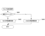
本実施例において、CPU110が実行するフローチャートを図14に示す。図14(a)は、ユーザが操作部113や不図示のリモコンにより、設置設定を開始した場合に起動される。
FIG. 14 shows a flowchart executed by the
まず、CPU110は、図8のステップS801あるいは図10のステップS1001と同様に、OSD重畳部320に指示をして図7(b)に示すズーム調整メニューを表示し、ユーザにズーム調整をさせる(ステップS1401)。
First, as in step S801 in FIG. 8 or step S1001 in FIG. 10, the
次に、CPU110は、図8のステップS803あるいは図10のステップS1002と同様に、OSD重畳部320に指示をして図7(d)に示すエッジブレンド設定メニューを表示し、ユーザにエッジブレンド設定をさせる(ステップS1402)。
次に、CPU110は、キーストーン補正を実施する(ステップS1403)。
Next, as in step S803 of FIG. 8 or step S1002 of FIG. 10, the
Next, the
ステップS1403の詳細フローを図14(b)に示す。
まず、CPU110は、不図示のOSD表示により、ユーザにマルチ投影であるか否かを選択させる(ステップS1411)。
A detailed flow of step S1403 is shown in FIG.
First, the
マルチ投影の場合(S1411:Yes)、CPU110は、図6のステップS601と同様の処理を行う。すなわち、ユーザにマルチ投影の基準となる1台目のプロジェクタ(基準プロジェクタ)か、基準プロジェクタに合わせる2台目以降のプロジェクタ(従属プロジェクタ)かを選択させる(ステップS1412)。
In the case of multi-projection (S1411: Yes), the
2台目以降のプロジェクタの場合(S1412:No)、CPU110は、図10のステップS1003と同様に、重畳領域キーストーン設定処理を行う(ステップS1413)。
In the case of the second and subsequent projectors (S1412: No), the
ステップS1411で単独投影が選択された場合(S1411:No)および、ステップS1412で基準プロジェクタが選択された場合(S1412:Yes)、CPU110は、不図示のOSD表示により、ユーザにキーストーン補正の方法を選択させる。ここでは、従来の縦横キーストーン補正と、4点指定キーストーン補正のどちらかを選択させる(ステップS1414)。
When the single projection is selected in step S1411 (S1411: No) and when the reference projector is selected in step S1412 (S1412: Yes), the
ステップS1414で4点指定キーストーンが選択された場合(S1414:Yes)、CPU110は、有効画像領域4点キーストーン補正を実施する(ステップS1415)。これは、ステップS1413の重畳領域キーストーン設定で重畳領域1140の四隅に表示していた変形マーカーを、有効画像領域の四隅に表示して移動対象点も有効画像領域としたものであり、一般的な4点指定キーストーン補正と同様である。すなわち、この4点キーストーン補正では、変形前の投影画像の位置と変形後の投影画像の位置との関係に基づき変形処理のパラメータが設定される。このような4点キーストーン補正による変形処理の設定を第2の設定モードという。
When the 4-point designated keystone is selected in step S1414 (S1414: Yes), the
ステップS1414で縦横キーストーンが選択された場合(S1414:No)、CPU110は、図8のステップS802と同様に、ユーザにキーストーン調整をさせる(ステップS1416)。
ステップS1413、S1415、S1416のいずれを終了した場合にも、CPU110は、キーストーン設定処理を終了する。
When the vertical / horizontal keystone is selected in step S1414 (S1414: No), the
When any of steps S1413, S1415, and S1416 is completed,
本実施例では、マルチ投影の2台目以降のプロジェクタの場合には、重畳領域の四隅を指定したキーストーン補正が実施できる。よって、実施例1と同様の効果があるのに加え、マルチ投影ではない場合および、マルチ投影の基準プロジェクタの場合には、所望のキーストーン補正の方法を選ぶことができるため、状況に応じた最適な設定方法を選択することができる。 In the present embodiment, in the case of the second and subsequent projectors of multi-projection, keystone correction can be performed by designating the four corners of the overlapping area. Therefore, in addition to the same effects as in the first embodiment, in the case of non-multi-projection and in the case of a multi-projection reference projector, a desired keystone correction method can be selected. An optimal setting method can be selected.
(その他の実施例)
本発明の目的は、前述した実施形態の機能を実現するソフトウェアのプログラムコードを記録した記憶媒体を、装置に供給することによっても、達成される。このとき、供給された装置の制御部を含むコンピュータ(またはCPUやMPU)は、記憶媒体に格納されたプログラムコードを読み出し実行する。
(Other examples)
The object of the present invention can also be achieved by supplying a storage medium storing software program codes for realizing the functions of the above-described embodiments to the apparatus. At this time, the computer (or CPU or MPU) including the control unit of the supplied apparatus reads and executes the program code stored in the storage medium.
この場合、記憶媒体から読み出されたプログラムコード自体が前述した実施形態の機能を実現することになり、プログラムコード自体及びそのプログラムコードを記憶した記憶媒体は本発明を構成することになる。 In this case, the program code itself read from the storage medium realizes the functions of the above-described embodiments, and the program code itself and the storage medium storing the program code constitute the present invention.
プログラムコードを供給するための記憶媒体としては、例えば、フレキシブルディスク、ハードディスク、光ディスク、光磁気ディスク、CD−ROM、CD−R、磁気テープ、不揮発性のメモリカード、ROM等を用いることができる。 As a storage medium for supplying the program code, for example, a flexible disk, a hard disk, an optical disk, a magneto-optical disk, a CD-ROM, a CD-R, a magnetic tape, a nonvolatile memory card, a ROM, or the like can be used.
また、上述のプログラムコードの指示に基づき、装置上で稼動しているOS(基本システムやオペレーティングシステム)等が処理の一部又は全部を行い、その処理によって前述した実施形態の機能が実現される場合も含まれる。 Further, the OS (basic system or operating system) running on the apparatus performs part or all of the processing based on the instruction of the program code, and the functions of the above-described embodiments are realized by the processing. Cases are also included.
さらに、記憶媒体から読み出されたプログラムコードが、装置に挿入された機能拡張ボードやコンピュータに接続された機能拡張ユニットに備わるメモリに書込まれ、前述した実施形態の機能が実現される場合も含まれる。このとき、そのプログラムコードの指示に基づき、その機能拡張ボードや機能拡張ユニットに備わるCPU等が実際の処理の一部又は全部を行う。 Further, the program code read from the storage medium may be written into a memory provided in a function expansion board inserted into the apparatus or a function expansion unit connected to the computer, and the functions of the above-described embodiments may be realized. included. At this time, based on the instruction of the program code, the CPU or the like provided in the function expansion board or function expansion unit performs part or all of the actual processing.
110:CPU、140:画像処理部、340:変形処理部 110: CPU, 140: Image processing unit, 340: Deformation processing unit
Claims (14)
投影する画像に対して幾何学的な変形を行う変形手段と、
前記変形手段による変形処理のパラメータを設定する設定手段と、
他のプロジェクタが投影する投影画像の一部と重畳させる重畳領域の4つの頂点を識別可能に投影している状態で、前記4つの頂点のうちのいずれかを選択し、選択されている頂点の位置を移動させる指示を入力するユーザ操作を受け付ける受け付け手段と、
を備え、
前記設定手段は、前記受け付け手段により選択された頂点の位置の移動に応じて、前記変形手段により投影する画像全体の変形を行うためのパラメータを設定するものであって、前記頂点の移動を行う前の前記4つの頂点の座標と移動を行った後の前記4つの頂点の座標との関係に基づいて前記変形処理のパラメータを設定し、
前記変形手段は設定されたパラメータに基づき変形を実行するプロジェクタ。 A projector constituting an image projection system for projecting one image by superimposing a part of a plurality of projection images projected by a plurality of projectors and connecting them on a screen,
Deformation means for performing geometric deformation on the projected image;
Setting means for setting parameters for deformation processing by the deformation means;
In a state where the four vertices of the overlapping region to be overlapped with a part of the projection image projected by another projector are identifiably projected, one of the four vertices is selected, and the selected vertex Receiving means for receiving a user operation for inputting an instruction to move the position;
With
The setting means sets parameters for performing deformation of the entire image projected by the deformation means according to movement of the position of the vertex selected by the receiving means, and moves the vertex. Based on the relationship between the coordinates of the previous four vertices and the coordinates of the four vertices after the movement, the parameters of the deformation process are set,
The deformation means is a projector that performs deformation based on a set parameter .
ことを特徴とする請求項1に記載のプロジェクタ。The projector according to claim 1.
投影する画像に対して幾何学的な変形を行う変形工程と、
前記変形工程による変形処理のパラメータを設定する設定工程と、
他のプロジェクタが投影する投影画像の一部と重畳させる重畳領域の4つの頂点を識別可能に投影している状態で、前記4つの頂点のうちのいずれかを選択し、選択されている頂点の位置を移動させる指示を入力するユーザ操作を受け付ける受け付け工程と、
を有し、
前記設定工程では、前記受け付け工程において選択された頂点の位置の移動に応じて、前記変形工程において投影する画像全体の変形を行うためのパラメータが設定されるものであって、前記頂点の移動を行う前の前記4つの頂点の座標と移動を行った後の前記4つの頂点の座標との関係に基づいて前記変形処理のパラメータが設定され、
前記変形工程では、設定されたパラメータに基づき変形が実行されるプロジェクタの制御方法。 A method for controlling a projector that constitutes an image projection system that projects a single image by superimposing a part of a plurality of projection images projected by a plurality of projectors and connecting them on a screen,
A deformation process for performing geometric deformation on the projected image;
A setting step for setting parameters for deformation processing by the deformation step;
In a state where the four vertices of the overlapping region to be overlapped with a part of the projection image projected by another projector are identifiably projected, one of the four vertices is selected, and the selected vertex An accepting step of accepting a user operation for inputting an instruction to move the position;
Have
In the setting step, a parameter for performing deformation of the entire image to be projected in the deformation step is set according to the movement of the position of the vertex selected in the receiving step, and the movement of the vertex is performed. Parameters for the deformation process are set based on the relationship between the coordinates of the four vertices before the movement and the coordinates of the four vertices after the movement,
And in the deformation step, it sets control method of a projector deformation Ru is performed based on the parameters.
ことを特徴とする請求項3に記載のプロジェクタの制御方法。The projector control method according to claim 3.
複数のプロジェクタは、基準となる基準プロジェクタと、基準プロジェクタに合わせて投影画像の位置を合わせる従属プロジェクタと、からなり、
基準プロジェクタは、
投影する画像に対して幾何学的な変形を行う変形手段と、
前記変形手段による変形処理のパラメータを設定する設定手段と、
従属プロジェクタが投影する投影画像の一部と重畳させる重畳領域の4つの頂点を識別可能に投影する投影手段と、
を備え、
前記設定手段は、自プロジェクタとスクリーンとの相対的な傾斜角に基づいて前記変形処理のパラメータを設定する第1の設定モードと、前記変形手段による変形を行う前の投影画像の位置と変形を行った後の投影画像の位置との関係に基づいて前記変形処理のパラメータを設定する第2の設定モードと、のいずれかを選択して前記変形処理のパラメータを設定し、
従属プロジェクタは、
投影する画像に対して幾何学的な変形を行う変形手段と、
前記変形手段による変形処理のパラメータを設定する設定手段と、
基準プロジェクタが投影する投影画像の一部と重畳させる重畳領域の4つの頂点を識別可能に投影している状態で、前記4つの頂点のうちのいずれかを選択し、選択されている頂点の位置を移動させる指示を入力するユーザ操作を受け付ける受け付け手段と、
を備え、
前記設定手段は、前記受け付け手段により選択された頂点の位置の移動に応じて、前記変形手段により投影する画像全体の変形を行うためのパラメータを設定するものであって、前記頂点の移動を行う前の前記4つの頂点の座標と移動を行った後の前記4つの頂点の座標との関係に基づいて前記変形処理のパラメータを設定し、前記変形手段は設定されたパラメータに基づき変形を実行する画像投影システム。 An image projection system for projecting one image by superimposing a part of a plurality of projection images projected by a plurality of projectors and joining them on a screen,
The plurality of projectors includes a reference projector serving as a reference, and a subordinate projector that adjusts the position of the projection image according to the reference projector.
The reference projector is
Deformation means for performing geometric deformation on the projected image;
Setting means for setting parameters for deformation processing by the deformation means;
Projecting means for projectably identifying the four vertices of the superimposed region to be superimposed on a part of the projection image projected by the subordinate projector;
With
The setting means includes a first setting mode for setting parameters of the deformation processing based on a relative inclination angle between the projector and the screen, and a position and deformation of a projection image before the deformation by the deformation means. A second setting mode for setting parameters for the deformation process based on the relationship with the position of the projected image after the setting, and setting the parameters for the deformation process by selecting any one of them,
Subordinate projectors
Deformation means for performing geometric deformation on the projected image;
Setting means for setting parameters for deformation processing by the deformation means;
In a state where the four vertices of the overlapping area to be superimposed on a part of the projection image projected by the reference projector are identifiably projected, any one of the four vertices is selected, and the position of the selected vertex Receiving means for receiving a user operation to input an instruction to move
With
The setting means sets parameters for performing deformation of the entire image projected by the deformation means according to movement of the position of the vertex selected by the receiving means, and moves the vertex. The deformation processing parameters are set based on the relationship between the coordinates of the previous four vertices and the coordinates of the four vertices after the movement, and the deformation means performs the deformation based on the set parameters. Image projection system.
基準プロジェクタの設定手段は、前記第1の設定モードにおいて、ユーザ操作により入力された傾斜角の情報に基づいて前記変形処理のパラメータを設定する請求項5又は6に記載の画像投影システム。 The reference projector includes an input unit that receives a user operation for inputting a relative inclination angle between the projector and the screen.
Setting means of the reference projector, the in the first setting mode, the image projection system according to claim 5 or 6 to set the parameters of the transformation process on the basis of the information of the tilt angle input by the user operation.
従属プロジェクタの前記受け付け手段は、前記マーカーの位置を移動させる指示を入力するユーザ操作を受け付け、
基準プロジェクタは、従属プロジェクタにおいて前記マーカーの位置を移動させるユーザ操作が行われているときに、ユーザが、前記マーカーの位置を基準プロジェクタの投影画像における重畳領域の位置に移動させることができるように、少なくとも基準プロジェクタの投影画像における重畳領域の投影を行う請求項5〜7のいずれか1項に記載の画像投影システム。 The subordinate projector comprises display means for displaying a marker at the position of the superimposed region in the projection image before the deformation by the deformation means,
The receiving unit of the subordinate projector receives a user operation for inputting an instruction to move the position of the marker;
The reference projector is configured to allow the user to move the position of the marker to the position of the overlapping region in the projection image of the reference projector when a user operation for moving the position of the marker is performed in the subordinate projector. The image projection system according to any one of claims 5 to 7, wherein projection of a superimposed region in at least a projection image of a reference projector is performed.
従属プロジェクタは、基準プロジェクタから基準プロジェクタの変形処理のパラメータの設定が完了したことの通知を受信する通信手段を備え、
従属プロジェクタの設定手段は、前記通信手段が前記通知を受信した後に、前記設定手段によるパラメータの設定を開始する請求項5〜8のいずれか1項に記載の画像投影システム。 The reference projector includes communication means for notifying the subordinate projector that the parameter setting by the setting means has been completed,
The subordinate projector includes communication means for receiving notification from the reference projector that the setting of the deformation processing parameters of the reference projector has been completed,
Setting the measure of the dependent projector, after the communication unit has received the notification, the image projection system according to any one of claims 5-8 for starting a set of parameters by the setting means.
複数のプロジェクタは、基準となる基準プロジェクタと、基準プロジェクタに合わせて投影画像の位置を合わせる従属プロジェクタと、からなり、 The plurality of projectors includes a reference projector serving as a reference, and a subordinate projector that adjusts the position of the projection image according to the reference projector.
基準プロジェクタが投影する画像に対して幾何学的な変形を行う第1の変形工程と、 A first deformation step for performing geometric deformation on the image projected by the reference projector;
前記第1の変形工程における変形処理のパラメータを設定する第1の設定工程と、 A first setting step for setting parameters for deformation processing in the first deformation step;
従属プロジェクタが投影する投影画像の一部と重畳させる重畳領域の4つの頂点を基準プロジェクタが識別可能に投影する投影工程と、 A projecting step in which the reference projector projects the four vertices of the superimposed region to be superposed on a part of the projection image projected by the subordinate projector, and
従属プロジェクタが投影する画像に対して幾何学的な変形を行う第2の変形工程と、 A second deformation step for performing geometric deformation on the image projected by the subordinate projector;
前記第2の変形工程における変形処理のパラメータを設定する第2の設定工程と、 A second setting step for setting parameters for deformation processing in the second deformation step;
基準プロジェクタが投影する投影画像の一部と重畳させる重畳領域の4つの頂点を識別可能に投影している状態で、前記4つの頂点のうちのいずれかが選択され、選択されている頂点の位置を移動させる指示を入力するユーザ操作が従属プロジェクタに受け付けられる受け付け工程と、 One of the four vertices is selected in a state where the four vertices of the overlapping region to be overlapped with a part of the projection image projected by the reference projector are identifiable, and the position of the selected vertex An accepting step in which a subordinate projector accepts a user operation to input an instruction to move
を有し、Have
前記第1の設定工程では、基準プロジェクタとスクリーンとの相対的な傾斜角に基づいて前記変形処理のパラメータを設定する第1の設定モードと、前記第1の変形工程における変形を行う前の投影画像の位置と変形を行った後の投影画像の位置との関係に基づいて前記変形処理のパラメータを設定する第2の設定モードと、のいずれかが選択されて前記変形処理のパラメータが設定され、 In the first setting step, a first setting mode for setting parameters of the deformation process based on a relative inclination angle between the reference projector and the screen, and a projection before performing the deformation in the first deformation step. One of the second setting mode for setting the deformation processing parameters based on the relationship between the position of the image and the position of the projected image after the deformation is selected, and the deformation processing parameters are set. ,
前記第2の設定工程では、前記受け付け工程において選択された頂点の位置の移動に応じて、前記第2の変形工程において投影する画像全体の変形を行うためのパラメータが設定されるものであって、前記頂点の移動を行う前の前記4つの頂点の座標と移動を行った後の前記4つの頂点の座標との関係に基づいて前記変形処理のパラメータが設定され、前記第2の変形工程では設定されたパラメータに基づき変形が実行される画像投影システムの制御方法。 In the second setting step, parameters for performing deformation of the entire image to be projected in the second deformation step are set according to the movement of the position of the vertex selected in the receiving step. The deformation processing parameters are set based on the relationship between the coordinates of the four vertices before the movement of the vertices and the coordinates of the four vertices after the movement, and in the second deformation step, A control method of an image projection system in which deformation is executed based on set parameters.
前記第1の設定工程では、前記第1の設定モードにおいて、ユーザ操作により入力された傾斜角の情報に基づいて前記変形処理のパラメータが設定される請求項10又は11に記載の画像投影システムの制御方法。 12. The image projection system according to claim 10, wherein, in the first setting step, the parameter of the deformation process is set based on information on an inclination angle input by a user operation in the first setting mode. Control method.
前記受け付け工程では、前記マーカーの位置を移動させる指示を入力するユーザ操作を受け付け、 In the reception step, a user operation for inputting an instruction to move the position of the marker is received,
前記投影工程では、従属プロジェクタにおいて前記マーカーの位置を移動させるユーザ操作が行われているときに、ユーザが、前記マーカーの位置を基準プロジェクタの投影画像における重畳領域の位置に移動させることができるように、少なくとも基準プロジェクタの投影画像における重畳領域の投影が行われる請求項10〜12のいずれか1項に記載の画像投影システムの制御方法。 In the projection step, when a user operation for moving the marker position is performed in the subordinate projector, the user can move the marker position to the position of the overlapping region in the projection image of the reference projector. The method of controlling an image projection system according to any one of claims 10 to 12, wherein at least the overlapping region in the projection image of the reference projector is projected.
前記第2の設定工程では、前記通信工程において前記通知が受信された後に、前記第2の設定工程におけるパラメータの設定が開始される請求項10〜13のいずれか1項に記載の画像投影システムの制御方法。 The image projection system according to any one of claims 10 to 13, wherein, in the second setting step, parameter setting in the second setting step is started after the notification is received in the communication step. Control method.
Priority Applications (3)
| Application Number | Priority Date | Filing Date | Title |
|---|---|---|---|
| JP2012225969A JP6164820B2 (en) | 2012-10-11 | 2012-10-11 | Projector, control method therefor, and image projection system |
| US14/047,379 US9906761B2 (en) | 2012-10-11 | 2013-10-07 | Projector, its control method, and image projection system |
| US15/854,530 US20180139427A1 (en) | 2012-10-11 | 2017-12-26 | Projector, its control method, and image projection system |
Applications Claiming Priority (1)
| Application Number | Priority Date | Filing Date | Title |
|---|---|---|---|
| JP2012225969A JP6164820B2 (en) | 2012-10-11 | 2012-10-11 | Projector, control method therefor, and image projection system |
Related Child Applications (1)
| Application Number | Title | Priority Date | Filing Date |
|---|---|---|---|
| JP2017116719A Division JP6345316B2 (en) | 2017-06-14 | 2017-06-14 | Projector, control method therefor, program, and storage medium |
Publications (2)
| Publication Number | Publication Date |
|---|---|
| JP2014078872A JP2014078872A (en) | 2014-05-01 |
| JP6164820B2 true JP6164820B2 (en) | 2017-07-19 |
Family
ID=50475068
Family Applications (1)
| Application Number | Title | Priority Date | Filing Date |
|---|---|---|---|
| JP2012225969A Active JP6164820B2 (en) | 2012-10-11 | 2012-10-11 | Projector, control method therefor, and image projection system |
Country Status (2)
| Country | Link |
|---|---|
| US (2) | US9906761B2 (en) |
| JP (1) | JP6164820B2 (en) |
Families Citing this family (40)
| Publication number | Priority date | Publication date | Assignee | Title |
|---|---|---|---|---|
| JP6322993B2 (en) * | 2013-12-19 | 2018-05-16 | カシオ計算機株式会社 | Geometric correction adjustment method |
| JP6564163B2 (en) * | 2014-04-23 | 2019-08-21 | アイキューブド研究所株式会社 | Image output apparatus, image output method, and program |
| JP6604710B2 (en) * | 2014-04-23 | 2019-11-13 | アイキューブド研究所株式会社 | Image output apparatus, image output method, and program |
| JP2016001781A (en) * | 2014-06-11 | 2016-01-07 | ソニー株式会社 | Information processing apparatus, information processing method, program, and image display device |
| JP6183305B2 (en) * | 2014-07-02 | 2017-08-23 | 株式会社デンソー | Failure detection apparatus and failure detection program |
| JP6456086B2 (en) * | 2014-09-25 | 2019-01-23 | キヤノン株式会社 | Projection type image display apparatus and control method thereof, projector and control method thereof |
| JP6525570B2 (en) * | 2014-12-04 | 2019-06-05 | キヤノン株式会社 | Image display system, control device, control method and program |
| KR101649051B1 (en) * | 2014-12-23 | 2016-08-18 | 광운대학교 산학협력단 | Calibration method of elemental image for elimination of keystone effect in reflective integral imaging system based on multiple projectors |
| JP6540099B2 (en) * | 2015-03-02 | 2019-07-10 | セイコーエプソン株式会社 | IMAGE PROCESSING DEVICE, DISPLAY DEVICE, AND IMAGE PROCESSING METHOD |
| JP6794092B2 (en) * | 2015-03-03 | 2020-12-02 | キヤノン株式会社 | Display device |
| US10474311B2 (en) * | 2015-05-28 | 2019-11-12 | Clemtek Llc | Gaming video processing system |
| JP6645687B2 (en) * | 2015-08-31 | 2020-02-14 | キヤノン株式会社 | Display device and control method |
| JP6659117B2 (en) * | 2015-10-29 | 2020-03-04 | キヤノン株式会社 | Image processing apparatus, image processing method, and program |
| CN108459455A (en) * | 2016-02-29 | 2018-08-28 | 青岛海信电器股份有限公司 | A kind of projection display system |
| CN110087047B (en) * | 2016-03-28 | 2021-05-14 | 麦克赛尔株式会社 | Projection type image display device |
| CN106200240A (en) * | 2016-07-13 | 2016-12-07 | 深圳市华星光电技术有限公司 | Projection arrangement and system |
| US10225535B2 (en) * | 2016-08-11 | 2019-03-05 | Rabin Esrail | Self-adjusting portable modular 360-degree projection and recording computer system |
| US9930307B1 (en) * | 2016-09-28 | 2018-03-27 | Intel Corporation | Projector image alignment |
| JP6897191B2 (en) * | 2017-03-17 | 2021-06-30 | セイコーエプソン株式会社 | Projector and projector control method |
| JP2019032495A (en) * | 2017-08-10 | 2019-02-28 | キヤノン株式会社 | Image projection device |
| US10536676B2 (en) * | 2017-08-10 | 2020-01-14 | Canon Kabushiki Kaisha | Projection apparatus, control method, and storage medium |
| JP6685264B2 (en) * | 2017-10-04 | 2020-04-22 | キヤノン株式会社 | Projection apparatus, control method thereof, and projection system |
| JP2019066806A (en) * | 2017-10-05 | 2019-04-25 | キヤノン株式会社 | Projection device and method of controlling the same, program, and storage medium |
| JP2019078786A (en) * | 2017-10-20 | 2019-05-23 | セイコーエプソン株式会社 | Image projection system, projector, and control method of image projection system |
| JP6515169B2 (en) * | 2017-11-30 | 2019-05-15 | マクセル株式会社 | Projection type video display |
| JP7096664B2 (en) * | 2017-12-15 | 2022-07-06 | キヤノン株式会社 | Projection control device and its control method, and projection system |
| JP7176190B2 (en) * | 2018-01-25 | 2022-11-22 | セイコーエプソン株式会社 | IMAGE DISPLAY DEVICE, IMAGE DISPLAY SYSTEM, AND IMAGE DISPLAY DEVICE CONTROL METHOD |
| JP7013896B2 (en) * | 2018-01-31 | 2022-02-01 | セイコーエプソン株式会社 | Projection system, projection system control method, projector |
| JP7022323B2 (en) | 2018-02-27 | 2022-02-18 | セイコーエプソン株式会社 | Image display system, image display device and control method of image display system |
| US10754237B2 (en) * | 2018-05-24 | 2020-08-25 | Canon Kabushiki Kaisha | Control apparatus, control method, projection system, and storage medium |
| JP6915597B2 (en) * | 2018-08-29 | 2021-08-04 | セイコーエプソン株式会社 | Controls, multi-projection systems, and control methods for controls |
| JP7238298B2 (en) * | 2018-09-03 | 2023-03-14 | セイコーエプソン株式会社 | Projectors and projector control methods |
| JP7162124B2 (en) | 2019-03-27 | 2022-10-27 | 富士フイルム株式会社 | Image processing device, projection system, image processing method, and image processing program |
| CN111918043B (en) * | 2019-05-10 | 2022-04-15 | 中强光电股份有限公司 | Projection system, projection screen adjusting method and projector |
| CN114630086A (en) * | 2020-12-11 | 2022-06-14 | 中强光电股份有限公司 | Projection system and image capturing quantity selection method for image splicing |
| US11575864B2 (en) * | 2021-03-22 | 2023-02-07 | Coretronic Corporation | Projection system and projection method |
| CN115343898A (en) * | 2021-04-27 | 2022-11-15 | 中强光电股份有限公司 | Projection system and projection image superposition method |
| EP4300951A1 (en) * | 2021-06-10 | 2024-01-03 | Samsung Electronics Co., Ltd. | Electronic apparatus and control method thereof |
| US11750778B2 (en) * | 2021-09-30 | 2023-09-05 | Coretronic Corporation | Method for adjusting pixel values of blending image and projection system thereof |
| CN116233569B (en) * | 2023-05-06 | 2023-07-11 | 石家庄铁道大学 | Video abstract generation method based on motion information assistance |
Family Cites Families (14)
| Publication number | Priority date | Publication date | Assignee | Title |
|---|---|---|---|---|
| JPH11355695A (en) * | 1998-06-10 | 1999-12-24 | Sony Corp | Video signal processor |
| JP2002116500A (en) * | 2000-10-05 | 2002-04-19 | Olympus Optical Co Ltd | Image projection/display device |
| JP3630166B2 (en) * | 2003-06-26 | 2005-03-16 | セイコーエプソン株式会社 | Adjusting the amount of distortion correction in the projected image |
| JP2005123669A (en) | 2003-10-14 | 2005-05-12 | Canon Inc | Projection type display apparatus |
| JP4026649B2 (en) * | 2005-02-16 | 2007-12-26 | セイコーエプソン株式会社 | Projector, projector control method, projector control program, and storage medium storing the program |
| US20070008344A1 (en) * | 2005-06-10 | 2007-01-11 | German Medina | Manipulation of Projected Images |
| JP2009200557A (en) * | 2008-02-19 | 2009-09-03 | Seiko Epson Corp | Projector, electronic apparatus, and method of controlling projector |
| JP2009200613A (en) * | 2008-02-19 | 2009-09-03 | Sharp Corp | Projector and display adjusting method of projector |
| JP5123747B2 (en) * | 2008-06-18 | 2013-01-23 | キヤノン株式会社 | Image display device and control method thereof |
| WO2010116837A1 (en) * | 2009-03-30 | 2010-10-14 | 日本電気株式会社 | Multiprojection display system and screen forming method |
| JP2011107563A (en) * | 2009-11-20 | 2011-06-02 | Seiko Epson Corp | Display system, image output device, control method, and recording medium |
| JP5641820B2 (en) * | 2010-08-25 | 2014-12-17 | キヤノン株式会社 | Projection type display system and projection type display device |
| JP6198605B2 (en) * | 2010-11-15 | 2017-09-20 | スケーラブル ディスプレイ テクノロジーズ インコーポレイテッド | System and method for calibrating a display system using manual and semi-automatic techniques |
| JP2012129594A (en) * | 2010-12-13 | 2012-07-05 | Seiko Epson Corp | Projector and method for screen shape correction of projector |
-
2012
- 2012-10-11 JP JP2012225969A patent/JP6164820B2/en active Active
-
2013
- 2013-10-07 US US14/047,379 patent/US9906761B2/en active Active
-
2017
- 2017-12-26 US US15/854,530 patent/US20180139427A1/en not_active Abandoned
Also Published As
| Publication number | Publication date |
|---|---|
| US20140104582A1 (en) | 2014-04-17 |
| JP2014078872A (en) | 2014-05-01 |
| US20180139427A1 (en) | 2018-05-17 |
| US9906761B2 (en) | 2018-02-27 |
Similar Documents
| Publication | Publication Date | Title |
|---|---|---|
| JP6164820B2 (en) | Projector, control method therefor, and image projection system | |
| JP6456086B2 (en) | Projection type image display apparatus and control method thereof, projector and control method thereof | |
| US10989993B2 (en) | Control device for correcting projection image, projection system, method of controlling same, and storage medium | |
| US20170214895A1 (en) | Projection apparatus, projection method, and storage medium | |
| JP6083185B2 (en) | Projector, projector black level area setting method | |
| US20170244941A1 (en) | Projector and control method thereof | |
| US9568812B2 (en) | Image projection apparatus and control method thereof | |
| JP2006165949A (en) | Projector system and projector | |
| US20190281266A1 (en) | Control apparatus, readable medium, and control method | |
| JP2018004919A (en) | Display and method for controlling the same | |
| JP6271837B2 (en) | Projection apparatus and control method thereof | |
| JP6794092B2 (en) | Display device | |
| JP2013083755A (en) | Display device, method of controlling display device, and program | |
| JP6345316B2 (en) | Projector, control method therefor, program, and storage medium | |
| JP6635748B2 (en) | Display device, display device control method, and program | |
| JP2019047355A (en) | projector | |
| JP7166775B2 (en) | Display device control device, control method, display system and program | |
| WO2020162051A1 (en) | Projection type video display system | |
| JP2018180105A (en) | Projection device and image projection method | |
| JP2019149633A (en) | Projector, control device, image projection system, control method, and program | |
| JP6700955B2 (en) | Projection apparatus and projection method | |
| JP2014137386A (en) | Projector, control method therefor, and image projection system | |
| JP2011248185A (en) | Projection type video display device | |
| JP2017102473A (en) | Projector and black level area setting method for the same | |
| JP2014036394A (en) | Distortion correction method of projection image and projection display device |
Legal Events
| Date | Code | Title | Description |
|---|---|---|---|
| A621 | Written request for application examination |
Free format text: JAPANESE INTERMEDIATE CODE: A621 Effective date: 20151008 |
|
| A977 | Report on retrieval |
Free format text: JAPANESE INTERMEDIATE CODE: A971007 Effective date: 20160727 |
|
| A131 | Notification of reasons for refusal |
Free format text: JAPANESE INTERMEDIATE CODE: A131 Effective date: 20160802 |
|
| A521 | Written amendment |
Free format text: JAPANESE INTERMEDIATE CODE: A523 Effective date: 20161003 |
|
| A131 | Notification of reasons for refusal |
Free format text: JAPANESE INTERMEDIATE CODE: A131 Effective date: 20170307 |
|
| TRDD | Decision of grant or rejection written | ||
| A01 | Written decision to grant a patent or to grant a registration (utility model) |
Free format text: JAPANESE INTERMEDIATE CODE: A01 Effective date: 20170523 |
|
| A61 | First payment of annual fees (during grant procedure) |
Free format text: JAPANESE INTERMEDIATE CODE: A61 Effective date: 20170620 |
|
| R151 | Written notification of patent or utility model registration |
Ref document number: 6164820 Country of ref document: JP Free format text: JAPANESE INTERMEDIATE CODE: R151 |