JP2017102473A - Projector and black level area setting method for the same - Google Patents
Projector and black level area setting method for the same Download PDFInfo
- Publication number
- JP2017102473A JP2017102473A JP2017008792A JP2017008792A JP2017102473A JP 2017102473 A JP2017102473 A JP 2017102473A JP 2017008792 A JP2017008792 A JP 2017008792A JP 2017008792 A JP2017008792 A JP 2017008792A JP 2017102473 A JP2017102473 A JP 2017102473A
- Authority
- JP
- Japan
- Prior art keywords
- black level
- region
- area
- projector
- guide
- Prior art date
- Legal status (The legal status is an assumption and is not a legal conclusion. Google has not performed a legal analysis and makes no representation as to the accuracy of the status listed.)
- Granted
Links
Images


Abstract
Description
本発明は、投写面に対し複数台のプロジェクターから各投写画像の一部が重複するように投写された場合の漏れ光による黒浮きを解消するために、非重複部分の黒レベルを調整する黒レベル調整が可能なプロジェクター、プロジェクターの黒レベル領域設定方法に関する。 The present invention provides a black image for adjusting the black level of a non-overlapping part in order to eliminate black floating due to leaked light when a part of each projected image is projected from a plurality of projectors on the projection surface. The present invention relates to a projector capable of level adjustment and a black level region setting method for the projector.
この種のプロジェクターとして、特許文献1が提案されている。当該特許文献1では、投写画像をカメラで撮像し、その撮像結果から黒レベルの調整対象領域となる黒レベル領域を特定している。
ところが、カメラを用いると、その分装置コストがアップしてしまう。また、特許文献1では、黒レベル領域の設定が、投写画像の範囲内に限定されている。このため、幾何学補正が行われた場合、光変調装置の全体に対して黒レベル領域を設定することができず、画像が形成されない非画像形成領域の漏れ光による黒浮きを解消できないといった問題がある。
However, when a camera is used, the cost of the apparatus increases accordingly. In
本発明は、上記の問題点に鑑み、カメラを用いることなく、黒レベル領域を設定可能なプロジェクター、プロジェクターの黒レベル領域設定方法を提供することを第1の目的とする。また、光変調装置の領域全体に黒レベル領域を設定可能なプロジェクター、プロジェクターの黒レベル領域設定方法を提供することを第2の目的とする。 In view of the above-described problems, a first object of the present invention is to provide a projector capable of setting a black level region without using a camera and a black level region setting method for the projector. It is a second object of the present invention to provide a projector capable of setting a black level region in the entire region of the light modulation device and a black level region setting method for the projector.
本発明のプロジェクターは、投写面に対し、自装置を含む複数台のプロジェクターから各投写画像の一部が重複するように投写される場合、重複領域の黒浮きを解消するため、黒レベルの調整対象領域である黒レベル領域を設定するプロジェクターであって、光変調装置によって変調された画像を投写面に投写する投写光学系と、投写画像のコンテンツに、重複領域と想定される重複想定領域が設定されている場合、当該重複想定領域の境界線上に、複数のガイドを略等間隔で配置して表示するガイド表示部と、ガイドの位置調整操作を受け付ける操作部と、操作部による位置調整操作後のガイドの配置に基づいて、黒レベル領域を設定する黒レベル領域設定部と、を備えたことを特徴とする。 The projector of the present invention adjusts the black level in order to eliminate the black floating in the overlapping area when the projection image is projected so that a part of each projection image overlaps from the plurality of projectors including the own apparatus on the projection surface. A projector that sets a black level region, which is a target region, includes a projection optical system that projects an image modulated by a light modulation device onto a projection surface, and an overlap assumption region that is assumed to be an overlap region in the content of the projection image. If set, a guide display unit that displays a plurality of guides arranged at substantially equal intervals on the boundary line of the assumed overlap region, an operation unit that receives a guide position adjustment operation, and a position adjustment operation by the operation unit And a black level area setting unit that sets a black level area based on the arrangement of the guides later.
上記のプロジェクターにおいて、ガイド表示部は、投写画像のコンテンツに、重複領域と想定される重複想定領域が設定されている場合、当該重複想定領域に基づく位置にガイドを配置して表示することを特徴とする。 In the projector described above, the guide display unit, when an overlap assumption region that is assumed to be an overlap region is set in the content of the projected image, displays the guide in a position based on the overlap assumption region. And
上記のプロジェクターにおいて、ガイド表示部は、重複想定領域の境界線上に、複数のガイドを略等間隔で配置して表示することを特徴とする。 In the projector described above, the guide display unit displays a plurality of guides arranged at substantially equal intervals on the boundary line of the overlap assumption region.
本発明のプロジェクターの黒レベル領域設定方法は、投写面に対し、自装置を含む複数台のプロジェクターから各投写画像の一部が重複するように投写される場合、重複領域の黒浮きを解消するため、黒レベルの調整対象領域である黒レベル領域を設定するプロジェクターの黒レベル領域設定方法であって、投写画像のコンテンツに、重複領域と想定される重複想定領域が設定されている場合、当該重複想定領域の境界線上に、複数のガイドを略等間隔で配置して表示するガイド表示ステップと、ガイドの位置調整操作を受け付ける操作ステップと、位置調整操作後のガイドの配置に基づいて、黒レベル領域を設定する黒レベル領域設定ステップと、を実行することを特徴とする。 The method for setting the black level area of the projector according to the present invention eliminates the black floating in the overlapping area when a part of each projected image is projected from a plurality of projectors including the own apparatus on the projection plane. Therefore, in the projector black level area setting method for setting the black level area, which is the black level adjustment target area, when the overlap assumption area assumed to be the overlap area is set in the projected image content, Based on the guide display step for arranging and displaying a plurality of guides at substantially equal intervals on the boundary line of the overlap assumption region, the operation step for accepting the guide position adjustment operation, and the guide placement after the position adjustment operation, black And a black level region setting step for setting the level region.
本発明の構成によれば、ユーザーが、投写画像上に表示されたガイドの位置調整操作を行うことにより黒レベル領域を設定するため、カメラを用いることなく黒レベル領域を設定することができる。また、重複投写におけるプロジェクターの配置や投写面の形状、幾何学補正の有無、ブレンディング処理の有無などの投写条件から黒レベル領域を演算などで求めるというような複雑な処理をすることなく、黒レベル領域を設定することができる。つまり、重複投写が行われた場合、ユーザーが、実際に投写されている投写画像を視認しながら、重複領域と非重複領域の境界に合わせてガイドの位置調整を行うことで、容易且つ正確に黒レベル領域を設定することができる。また、重複領域と想定される重複想定領域の境界線上に複数のガイドが配置されるため、何もない状態からガイドを配置していく場合と比較して、短時間で操作を終えることができる。 According to the configuration of the present invention, since the user sets the black level region by adjusting the position of the guide displayed on the projected image, the black level region can be set without using a camera. In addition, the black level can be obtained without performing complicated processing such as calculating the black level region from the projection conditions such as projector layout, projection surface shape, geometric correction, blending processing, etc. An area can be set. In other words, when overlapping projection is performed, the user can easily and accurately adjust the position of the guide according to the boundary between the overlapping region and the non-overlapping region while visually recognizing the projected image being projected. A black level region can be set. In addition, since a plurality of guides are arranged on the boundary line of the assumed overlapping area, the operation can be completed in a short time compared to the case where the guides are arranged from nothing. .
上記のプロジェクターにおいて、操作部は、光変調装置の領域全体を対象として、各ガイドの位置調整が可能であることを特徴とする。 In the projector described above, the operation unit can adjust the position of each guide for the entire region of the light modulation device.
本発明の構成によれば、幾何学補正が行われた場合でも、光変調装置の領域全体に黒レベル領域を設定することができる。通常、幾何学補正を行う場合、光変調装置において投写画像に対応する画像形成領域を縮小するため、空白領域(ブランキング)が発生する。この空白領域は、黒色が設定されるものの、重複投写が行われた場合、漏れ光により黒浮きの対象となる。このため、光変調装置の領域全体に対して黒レベル領域を設定可能とすることにより、光変調装置の画像形成領域だけでなく、画像が形成されない非画像形成領域の漏れ光による黒浮きについても解消することができる。 According to the configuration of the present invention, it is possible to set the black level region in the entire region of the light modulation device even when geometric correction is performed. Normally, when geometric correction is performed, a blank area (blanking) occurs in order to reduce an image forming area corresponding to a projected image in the light modulation device. Although this blank area is set to black, when overlapping projection is performed, the blank area becomes an object of black floating due to leakage light. Therefore, by making it possible to set the black level region for the entire region of the light modulation device, not only the image formation region of the light modulation device but also the black floating due to the leaked light in the non-image formation region where no image is formed. Can be resolved.
上記のプロジェクターにおいて、重複領域を目立たなくするためのブレンディング処理を行うブレンディング処理部をさらに備え、ガイド表示部は、ブレンディング処理が行われた場合、位置調整操作前の初期状態において、当該ブレンディング処理の対象領域であるブレンディング領域の境界線上に、複数のガイドを配置することを特徴とする。 The above projector further includes a blending processing unit that performs a blending process for making the overlapping region inconspicuous, and the guide display unit performs the blending process in an initial state before the position adjustment operation when the blending process is performed. A plurality of guides are arranged on the boundary line of the blending area as the target area.
本発明の構成によれば、ブレンディング処理は、一般的に重複投写が行われた場合の重複領域に対して行われるため、ブレンディング領域の境界線上に複数のガイドを配置することで、重複領域を特定する処理を省略することができる。 According to the configuration of the present invention, since the blending process is generally performed on the overlapping area when overlapping projection is performed, the overlapping area is reduced by arranging a plurality of guides on the boundary line of the blending area. The processing to specify can be omitted.
上記のプロジェクターにおいて、投写画像の歪みを補正するための幾何学補正を行う幾何学補正部をさらに備え、ガイド表示部は、幾何学補正の設定に応じて、表示するガイドの数を可変することを特徴とする。 The above projector further includes a geometric correction unit that performs geometric correction for correcting distortion of the projected image, and the guide display unit varies the number of guides to be displayed according to the setting of the geometric correction. It is characterized by.
本発明の構成によれば、幾何学補正は、投写面の状態に応じて行われることが多いため、幾何学補正の設定に応じてガイド数を可変することで、投写面の状態に応じた適切な黒レベル領域の設定が可能となる。
なお、幾何学補正とは、ポイント補正、弓型補正、台形補正等を指す。
According to the configuration of the present invention, since geometric correction is often performed according to the state of the projection surface, the number of guides can be changed according to the setting of the geometric correction, so that the geometric correction is performed according to the state of the projection surface. An appropriate black level region can be set.
Geometric correction refers to point correction, bow correction, trapezoid correction, and the like.
上記のプロジェクターにおいて、幾何学補正部は、幾何学補正として、投写画像を格子状に区切った各交点の位置調整により投写画像の歪みを補正するポイント補正、および投写画像の上下左右の各辺に対して弧状の補正を行う弓型補正の少なくとも一方が可能であり、ガイド表示部は、ポイント補正の交点数、および弓型補正の有無の少なくとも一方に応じて、表示するガイドの数を可変することを特徴とする。 In the projector described above, the geometric correction unit includes, as geometric correction, point correction that corrects distortion of the projected image by adjusting the position of each intersection obtained by dividing the projected image in a grid pattern, and the upper, lower, left, and right sides of the projected image. At least one of arcuate correction for performing arcuate correction is possible, and the guide display unit varies the number of guides to be displayed according to at least one of the number of point correction intersections and the presence or absence of arcuate correction. It is characterized by that.
本発明の構成によれば、ポイント補正や弓型補正が行われている場合、投写画像の重複部分の境界の形状が複雑になる場合が多いため、ガイドの数を増やすことで、より適切に黒レベル領域を設定することができる。また、ポイント補正において交点数を任意に選択できる場合は、交点数が多いほど複雑な補正が行われていると考えられるため、ガイドの数を増やすことが好ましい。 According to the configuration of the present invention, when the point correction or the bow correction is performed, the shape of the boundary of the overlapped portion of the projected image is often complicated, so it is more appropriate to increase the number of guides. A black level region can be set. Further, when the number of intersections can be arbitrarily selected in the point correction, it is considered that the more complex the correction is performed, the larger the number of intersections. Therefore, it is preferable to increase the number of guides.
上記のプロジェクターにおいて、ガイド表示部は、複数のガイドと共に、ガイド間を繋ぐガイドラインを表示し、黒レベル領域設定部は、操作部による位置調整操作後のガイドラインおよび光変調装置の枠によって構成される領域が閉じた領域とならない場合、ガイドラインの端部を光変調装置の枠まで延長させて複数の閉じた領域を形成し、当該複数の閉じた領域のうち1以上の領域を、黒レベル領域として設定することを特徴とする。 In the projector described above, the guide display unit displays a guideline connecting the guides together with a plurality of guides, and the black level region setting unit is configured by the guideline after the position adjustment operation by the operation unit and the frame of the light modulation device. If the region does not become a closed region, the end of the guide line is extended to the frame of the light modulation device to form a plurality of closed regions, and one or more of the plurality of closed regions is set as a black level region It is characterized by setting.
本発明の構成によれば、ガイドラインの端部を延長するため、ユーザーは、必ずしも光変調装置の枠にガイドラインが到達するまでガイドの位置調整を行う必要がない。このため、ガイドの位置調整に要する操作時間を短縮できる。
なお、複数の閉じた領域のうち1以上の領域(黒レベル領域)は、ブレンディング領域を含まない領域を設定することが好ましい。この構成によれば、ガイドの位置調整後に、黒レベル領域を指定するユーザーの手間を省略できる。
According to the configuration of the present invention, since the end portion of the guide line is extended, the user does not necessarily need to adjust the position of the guide until the guide line reaches the frame of the light modulation device. For this reason, the operation time required for the position adjustment of the guide can be shortened.
In addition, it is preferable to set an area not including a blending area as one or more areas (black level areas) among a plurality of closed areas. According to this configuration, it is possible to save the user's trouble of specifying the black level region after adjusting the position of the guide.
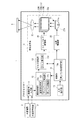
以下、添付の図面を参照し、本発明の一実施形態について説明する。図1は、プロジェクター1の構成を示すブロック図である。同図に示すように、プロジェクター1は、画像信号入力部11、画像処理部12、OSD処理部13、投写光学系14、入力操作部15、およびこれらを制御する制御部16を備えている。
Hereinafter, an embodiment of the present invention will be described with reference to the accompanying drawings. FIG. 1 is a block diagram showing the configuration of the
画像信号入力部11は、パーソナルコンピューターやDVDプレーヤー等の外部機器2、またはUSBメモリーやコンパクトフラッシュ(登録商標)等の外部記憶媒体3から画像信号を入力する。
The image signal input unit 11 inputs an image signal from an
画像処理部12は、画像信号入力部11により入力された画像信号に対し、予め記憶されている画像処理プログラムに基づいて、所定の画像処理を実行する。特に本実施形態では、幾何学補正部12a、ブレンディング処理部12bおよび黒レベル調整部12cとして機能する。なお、画像処理としては、これら以外に、解像度変換、シャープネス調整、輝度調整等の画質調整も含まれる。
The
幾何学補正部12aは、投写画像Gの歪みを補正するため、ポイント補正、弓型補正、台形補正等の幾何学補正を行う。ここで、ポイント補正とは、プロジェクター1を複数台並べて投写した場合の部分的な歪みを補正したり、重複部分の位置を調整したりするものである。補正方法としては、投写画像Gを格子状に区切った各交点をユーザーが上下左右に位置調整し、その位置調整結果に基づいて補正を行う。なお、ポイント補正を行う際は、交点数(ポイント数)として、「3×3」、「5×5」、「9×9」のいずれかを選択可能となっている。また、弓型補正とは、投写面(スクリーン)のたるみや縮みによる湾曲した画像の歪みを微調整するものである。補正方法としては、ユーザーが投写画像Gの上下左右の辺の中から補正対象となる辺を選択して補正量を指定し、その補正量に基づいて対象となる辺に対し弧状の補正を行う。また、台形補正とは、投写面に対する投写角度のずれによる投写画像Gの歪みを調整するものである。補正方法としては、縦台形補正、横台形補正、角部台形補正のいずれかを選択可能であり、ユーザーが指定した補正量に基づいて対象となる辺(または対象となる角)の角度補正・位置補正を行う。
The
ブレンディング処理部12bは、プロジェクター1を複数台並べて投写した場合の、投写画像Gの繋ぎ目(重複部分)を目立たなくする処理を行う。例えば、図2の例では、4台のプロジェクター1から投写された投写画像G1〜G4のうち、投写画像G3と投写画像G4の重複部分(投写画像G3の右側および投写画像G4の左側)にブレンディング処理を行った場合を示している。ブレンディング処理を行う場合、ユーザーは入力操作部15を操作して、ブレンディング領域65の範囲指定を行い、さらにブレンド曲線(グラデーションのかけ方)を指定する。ブレンディング処理部12bは、これらの指定に従い、ブレンディング領域65に対して、グラデーションをかける処理を行う。
The blending
なお、ブレンディング領域65は、プロジェクター1にて、ユーザーが範囲指定するのではなく、画像コンテンツに応じて予め設定されていても良い。例えば、複数台のプロジェクター1の上位装置となるPC(ビデオカード)により、マルチプロジェクションするための画像コンテンツと、各プロジェクター1の投写配置とに基づいてブレンディング領域65を設定し、その設定情報を各プロジェクター1に供給する画像コンテンツに付加して提供する構成でも良い。
The blending
また、各プロジェクター1には、必ずしも異なる画像コンテンツを供給する必要はなく、同じ画像コンテンツを供給しても良い。この場合は、各プロジェクター1にて、ユーザーが画像コンテンツの拡大/縮小およびパンニング等の設定を行い、その後ブレンディング領域65の範囲指定を行えば良い。
Further, it is not always necessary to supply different image contents to each
黒レベル調整部12cは、暗い画像を表示したときに、投写画像Gの重複部分が明るくなってしまうこと(以下、「黒浮き」と称する)を防ぐため、非重複部分の明るさや色味を補正する処理を行う。なお、黒レベル調整(カラー調整)については後述する。 The black level adjustment unit 12c adjusts the brightness and color of the non-overlapping part to prevent the overlapping part of the projected image G from becoming bright (hereinafter referred to as “black float”) when displaying a dark image. Perform correction processing. The black level adjustment (color adjustment) will be described later.
OSD処理部13は、制御部16の命令に基づいて、設定・操作画面やメッセージ等のOSD(On-Screen Display)情報を生成し、画像処理部12から入力される画像信号に重畳する。例えば、後述する黒レベル調整画面D1およびカラー調整画面D2(図4(a),(b)参照)も、OSD処理部13により表示される。
The
また、OSD処理部13は、ガイド表示部13aとして機能する。ガイド表示部13aは、黒レベル領域Ebを設定するためのガイド51と、ガイド51間を直線で繋ぐガイドライン52を表示する(図5〜8参照)。なお、ガイド51の位置調整については、後に詳述する。なお、OSD処理部13は、制御部16からOSD画像を重畳する命令がない場合、画像処理部12から入力される画像信号を、そのままライトバルブ駆動部24に出力する。
The
投写光学系14は、スクリーン等の投写面S上に画像を投写するものであり、光源部21、光源駆動部22、液晶ライトバルブ23(光変調装置)、ライトバルブ駆動部24および投写レンズ25を有している。
The projection
光源部21は、ハロゲンランプ、メタルハライドランプまたは高圧水銀ランプ等から成る光源ランプ21aと、光源ランプ21aから射出した光を略一定の方向に反射するリフレクター21bとにより構成される。光源部21から射出された光は、不図示の光分離光学系によって、赤色(R)、緑色(G)、青色(B)の色成分に分離された後、各色用の液晶ライトバルブ23(23R、23G、23B)に入射される。光源駆動部22は、制御部16から命令に基づいて、光源部21の点灯および消灯を切り替える。
The light source unit 21 includes a light source lamp 21a composed of a halogen lamp, a metal halide lamp, a high-pressure mercury lamp, or the like, and a
液晶ライトバルブ23は、一対の透明基板間に液晶が封入された液晶パネル等によって構成される。液晶ライトバルブ23には、複数の画素がマトリクス状に配列された矩形の画素領域23aが形成されている。ライトバルブ駆動部24は、液晶ライトバルブ23(画素領域23a)の各画素に、画像情報に応じた駆動電圧を印加することにより、各画素の光透過率を制御する。
The liquid crystal
上記の構成により、投写光学系14では、光源部21から射出された光が、液晶ライトバルブ23の画素領域23aを透過することによって変調され、画像信号に応じた画像が色光毎に形成される。形成された各色の画像は、不図示の光合成光学系(ダイクロイックプリズムなど)により画素毎に合成され、投写レンズ25によって投写面Sに投写される。
With the above configuration, in the projection
入力操作部15は、ユーザーからの入力操作を受け付ける操作手段(例えば、操作パネル)であり、複数の操作キーを備えている。ユーザーが入力操作部15の各種操作キーを操作すると、入力操作部15は、ユーザーの操作内容に応じた操作信号を制御部16に出力する。本実施形態では、主にガイド51の位置調整、OSD画面の操作等に用いる。なお、操作手段として、遠隔操作を行うためのリモコンを用いて良い。この場合、リモコンからの操作信号(赤外線)を受光する信号受光部をプロジェクター1本体に設ければ良い。
The
制御部16は、CPU(Central Processing Unit)、ROM(Read Only Memory)およびRAM(Random Access Memory)等により構成され、各部との信号の入出力を行うことによりプロジェクター1を統括制御する。また、制御部16は、黒レベル領域設定部16aとして機能する。黒レベル領域設定部16aは、ユーザーによって位置調整されたガイド51の配置に基づいて、黒レベル領域Ebを設定する(図9〜図11参照)。黒レベル領域Ebの設定についても、後に詳述する。
The
なお、制御部16は、上記の幾何学補正部12a、ブレンディング処理部12bおよび黒レベル調整部12cに対する処理命令、およびガイド表示部13aに対する表示命令も行う。したがって、請求項における、これら各部は、制御部16と画像処理部12、若しくは制御部16とOSD処理部13が協働することにより実現される。
The
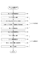
次に、図3のフローチャートおよび図4の画面表示を参照し、黒レベル調整処理の流れについて説明する。図3において、実線枠はプロジェクター1の動作、点線枠はユーザーの操作を示す。また、本処理の前に、ブレンディング処理が行われ、ブレンディング領域65が確定しているものとする。なお、ブレンディング処理を行っていない領域に対して、黒レベル調整を行うように処理を行ったとしても、幾何学補正などの要因により黒浮きする部分が残ってしまう場合があるため、黒レベル領域Ebの設定を行って黒レベルを調整する(黒浮きしない部分の輝度を上げる)本処理は有用である。
Next, the flow of black level adjustment processing will be described with reference to the flowchart of FIG. 3 and the screen display of FIG. In FIG. 3, a solid line frame indicates the operation of the
プロジェクター1(制御部16)は、ユーザーにより黒レベル調整が指示されると、黒レベル調整画面D1をOSD表示する(S01)。図4(a)に示すように、黒レベル調整画面D1は、エリア補正ボタン31、カラー調整ボタン32および初期化ボタン33を含む。エリア補正ボタン31が選択されるとエリア補正処理を行い、カラー調整ボタン32が選択されるとカラー調整処理を行う。また、初期化ボタン33が選択されると、エリア補正値およびカラー調整値を初期化する。ここでは、まずエリア補正ボタン31が選択されたものとする(S02)。
When the black level adjustment is instructed by the user, the projector 1 (control unit 16) displays the black level adjustment screen D1 by OSD (S01). As shown in FIG. 4A, the black level adjustment screen D1 includes an area correction button 31, a color adjustment button 32, and an
黒レベル調整画面D1でエリア補正ボタン31が選択されると、複数のガイド51および各ガイド51間を繋ぐガイドライン52を、液晶ライトバルブ23の画素領域23aにおけるブレンディング領域65の境界線上に形成する(初期状態の表示)。このとき、投写面S上では、これらガイド51およびガイドライン52を投写画像G(黒のラスター画像)に重畳表示する(S03)。ユーザーは、投写面Sを見ながら、位置調整の対象となる対象ガイド51dの選択およびその位置調整操作を行う(S04)。もっとも、ブレンディング領域65と投写画像Gの重複領域が完全に一致する場合、位置調整操作の必要はない。ユーザーの位置調整操作が確定すると、プロジェクター1は、確定した時点におけるガイドライン52の配置に基づいて、黒レベル領域Ebを設定する(S05)。以上、S02〜S05がエリア補正処理の流れである。
When the area correction button 31 is selected on the black level adjustment screen D1, a plurality of
エリア補正処理後、プロジェクター1は、再度黒レベル調整画面D1(図4(a)参照)を表示する(S06)。ここでは、カラー調整ボタン32が選択されたものとする(S07)。カラー調整ボタン32が選択されると、カラー調整画面D2をOSD表示する(S08)。図4(b)に示すように、カラー調整画面D2は、明るさ補正ゲージ41、色補正(緑−赤)ゲージ42および色補正(青−黄)ゲージ43を含む。ユーザーがこれらを用いて明るさおよび色味の調整操作を行い、さらに確定操作を行うと(S09)、プロジェクター1は、黒レベル領域Ebに対する黒レベル調整(黒色に対する明るさおよび色味の調整)を行う(S10)。
After the area correction process, the
具体的には、カラー調整画面D2において、明るさ補正ゲージ41に対する操作が行われると、黒レベル領域Ebの黒レベルを調整する。また、色補正(緑−赤)ゲージ42に対する操作が行われると、黒レベル領域Ebの緑色と赤色の間で色味を調整する。さらに、色補正(青−黄)ゲージ43に対する操作が行われると、黒レベル領域Ebの青色と黄色の間で色味を調整する。以上、S07〜S10がカラー調整処理の流れである。
Specifically, when an operation is performed on the brightness correction gauge 41 on the color adjustment screen D2, the black level of the black level region Eb is adjusted. Further, when an operation is performed on the color correction (green-red)
なお、上記の黒レベル調整処理前に実行されるブレンディング処理において、ブレンディング領域65の設定が変更されると、黒レベル調整処理の設定(エリア補正値およびカラー調整値)は、解除(初期化)される。また、初期化された場合(初期化ボタン33が選択された場合や、ブレンディング領域65の設定が変更された場合など)、図4(a)の黒レベル調整画面D1において、カラー調整ボタン32は、選択不可となる(グレーアウトされる)。つまり、カラー調整ボタン32は、黒レベル領域Ebが設定された状態のみ、選択可能となる。
In the blending process executed before the black level adjustment process, when the setting of the blending
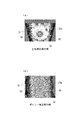
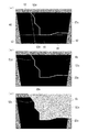
以下、図5以降を参照し、エリア補正処理の詳細(黒レベル領域Ebの設定)について、詳述する。まず、図5および図6を参照し、ガイド表示(エリア補正ボタン31押下後の初期状態の表示)について説明する。図5(a),(c)は、幾何学補正が行われていない場合のガイド表示例を示している。 Hereinafter, details of the area correction processing (setting of the black level region Eb) will be described in detail with reference to FIG. First, the guide display (display of the initial state after the area correction button 31 is pressed) will be described with reference to FIGS. 5A and 5C show guide display examples when geometric correction is not performed.
両図に示すように、ガイド表示は、外部機器2から入力された画像ではなく、黒のラスター画像上に重畳表示される。黒のラスター画像を表示するのは、投写画像Gの黒浮きしている部分(明るい部分)と黒浮きしていない部分(暗い部分)を目視で確認しやすくするためである。また、ガイド表示中は、黒レベル領域Ebの範囲指定操作を妨げないよう、黒レベルが調整されていない状態で黒のラスター画像を表示する。また、同図では1台のプロジェクター1についてのみ言及しているが、黒レベル領域Ebの範囲指定操作中は、投写面Sに対して重複投写させている他のプロジェクター1も、同様に黒のラスター画像を表示させることが好ましい。
As shown in both figures, the guide display is not superimposed on the image input from the
図5(a)は、投写画像Gの左側でブレンディング処理が行われた場合のガイド表示例を示している。このとき想定される投写状態は、図5(b)に示すとおりである。つまり、投写画像G1,G2が左右横並び状態で投写された場合、網掛け表示した投写画像G2は、左側領域がブレンディング領域65として設定される。このため、投写画像G2を投写するプロジェクター1は、液晶ライトバルブ23の画素領域23aにおいて、ブレンディング処理が有効となる左側(ブレンディング領域65の端)に、ガイド51およびガイドライン52を表示する。
FIG. 5A shows an example of a guide display when blending processing is performed on the left side of the projected image G. The projection state assumed at this time is as shown in FIG. That is, when the projected images G1 and G2 are projected in the horizontal direction, the left side region of the shaded projection image G2 is set as the blending
このときガイド51およびガイドライン52は、白色で表示される。また、ガイドライン52は、画素領域23aにおいて直線となる。また、ガイド51は、ガイドライン52に対して略等間隔に配置され、その数は幾何学補正の設定に応じて可変する。例えば、同図の例では、1辺のガイドライン52に対し、端の2点と間に3点の合計5点のガイド51を示しているが、ポイント補正や弓形補正を行っている場合は、投写面Sが平面でなく、投写画像Gの重複部分の形状が複雑になる(=黒レベル領域Ebの形状が複雑になる)ことが想定されるため、ガイド数を基準となる数より増やすことが好ましい。また、ポイント補正を行う際は、交点数を、「3×3」、「5×5」、「9×9」中から選択可能であるが、交点数の増加に伴って、ガイド数を増やすことが好ましい。また、台形補正は、一般的に投写面Sが平面の場合に行う補正であるため、台形補正を行っている場合は、ガイド数を基準となる数より減らしても良い。
At this time, the
一方、図5(c)は、投写画像Gの上側、左側および右側でブレンディング処理が行われた場合のガイド表示例を示している。このとき想定される投写状態は、図5(d)に示すとおりである。つまり、投写画像G1〜G6によって、同図のようにマルチプロジェクションされた場合、網掛け表示した投写画像G5は、上側、左側および右側領域がブレンディング領域65として設定される。このため、投写画像G5を投写するプロジェクター1は、画素領域23aにおいて、ブレンディング処理が有効となる上側、左側および右側(ブレンディング領域65の内側の端)に、ガイド51およびガイドライン52を表示する。
On the other hand, FIG. 5C shows an example of guide display when blending processing is performed on the upper side, the left side, and the right side of the projected image G. The projection state assumed at this time is as shown in FIG. In other words, when the projection images G1 to G6 are multi-projected as shown in the figure, the upper, left and right areas of the projected image G5 displayed as shaded areas are set as the blending
また、図6(a),(b)は、幾何学補正が行われている場合のガイド表示例(エリア補正ボタン31押下後の初期状態の表示例)を示している。図6(a)は、台形補正が行われ、且つ投写画像Gの左側および右側でブレンディング処理が行われた場合を示している。また、図6(b)は、ポイント補正が行われ、且つ投写画像Gの左側および右側でブレンディング処理が行われた場合のガイド表示例を示している。このように幾何学補正が行われた場合、画素領域23aにおいて、画像形成領域61(投写画像Gに対応する画像が形成される領域)が縮小されるため、非画像形成領域62が発生する。この場合、ガイド51およびガイドライン52は、画像形成領域61内におけるブレンディング領域65の境界線上に表示されるため、画像形成領域61の範囲内での表示となる。また、幾何学補正が行われた場合でも、ガイドライン52は、画素領域23aにおいて直線となる。
FIGS. 6A and 6B show a guide display example (display example of an initial state after the area correction button 31 is pressed) when geometric correction is performed. FIG. 6A shows a case where keystone correction is performed and blending processing is performed on the left and right sides of the projected image G. FIG. 6B shows an example of guide display when the point correction is performed and the blending process is performed on the left side and the right side of the projection image G. When geometric correction is performed as described above, the
次に、図7および図8を参照し、ガイド51の位置調整について説明する。同図(a)〜(g)に示すように、ユーザーは、入力操作部15に設けられた上下左右キーを用いて、位置調整の対象となる対象ガイド51dを選択する。選択確定操作前の仮選択状態のガイド51tは、他のガイド51と異なる色(例えば、オレンジ色)で表示され、Enterキーの押下により、確定状態となる(対象ガイド51dとなる,同図(g)参照)。対象ガイド51dは、例えばオレンジ色の二重枠で表示される。また、Escキーの押下により、対象ガイド51dは、仮選択状態に戻る(同図(f)参照)。
Next, the position adjustment of the
図8(a)は、対象ガイド51dの画像形成領域61内における位置調整例を示し、同図(b)は、対象ガイド51dの非画像形成領域62内における位置調整例を示している。なお、同図(b)は、台形補正が行われた場合を示している。いずれの場合も対象ガイド51dは、入力操作部15の上下左右キーの押下により、1pixelずつ移動する。また、上下左右キーのいずれかを押下し続けると、押下時間に比例して対象ガイド51dが移動する(オートリピート)。但し、対象ガイド51dの移動により、ガイドライン52上におけるガイド51の位置関係が入れ替わることはない。また、隣り合うガイド51に対して、所定長さ(例えば、9pixel)以上近づく移動はできない。
FIG. 8A shows an example of position adjustment of the
また、同図(b)に示すように、非画像形成領域62内への対象ガイド51dの移動が可能である。この場合、対象ガイド51dの移動に伴ってガイドライン52も延長する。このように、対象ガイド51dは、画素領域23a全体で移動可能となっている。ユーザーは、以上の操作により、投写面S上で黒浮きしている部分と黒浮きしていない部分の境界上に、各ガイド51を配置していく。また、ガイド51の位置調整操作を終了すると、確定操作(例えば、Enterキーの押下)を行い、ガイド表示を終了させる。なお、同図(b)の場合、画像形成領域61は黒ラスター画像が表示され、非画像形成領域62はブランキングで黒色となる。これに代えて、画素領域23a全体を黒ラスター画像とし、画像形成領域61と非画像形成領域62を区別するために、例えば黒色と灰色で色分けしても良い。
Further, as shown in FIG. 5B, the
なお、エリア補正処理の途中で、ユーザー操作により、表示するガイド51の数を任意に変更することが可能である。例えば、ガイド数が増やされた場合、ガイドライン52に対してガイド51が平均的に追加されるが、ガイドライン52の形状は更新されない(変化しない)。逆に、ガイド数が減らされた場合は、ガイドライン52に対してガイド51が平均的に間引きされ、それに伴ってガイドライン52の形状が更新される。
During the area correction process, the number of
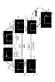
次に、図9〜図11を参照し、ガイド51の位置調整操作終了後における黒レベル領域Ebの設定について説明する。図9は、台形補正が行われ、且つ左側および右側でブレンディング処理が行われ、且つガイドライン52が同図(a)の状態(2本非交差型)で確定された場合を示している。なお、同図(a)において、点線で囲った2つの領域は、ブレンディング処理の対象となったブレンディング領域65を示している。つまり、同図の左側および右側は、他の投写画像Gとの重複領域となっている。また、符号52dは、ガイド51の位置調整操作により確定されたガイドライン52(以下、「確定ガイドライン52d」と称する)を示している。
Next, the setting of the black level region Eb after the position adjustment operation of the
同図(b)に示すように、プロジェクター(制御部16)は、ガイドライン52の端部が画素領域23aの枠まで達していない場合(ガイドライン52および画素領域23aの枠によって構成される領域が閉じた領域とならない場合)、ガイドライン52の端部を画素領域23aの枠まで延長させる。符号52eは、ガイドライン52の延長部分(以下、「延長ガイドライン52e」と称する)を示している。このように、確定ガイドライン52dに延長ガイドライン52eを付加することにより、同図に示す画素領域23aには、3つの閉じた領域が形成される。このうち、同図(a)に示したブレンディング領域65を含まない領域(若しくはブレンディング領域65を含む割合が小さい領域)を、黒レベル領域Ebとして設定する。つまり、3つの閉じた領域のうち、他の投写画像Gと重複していない領域を、黒レベル領域Ebとして設定する。同図(c)に示すように、設定された黒レベル領域Ebに対しては、図4(b)に示したカラー調整画面D2の設定に基づいて、黒レベルを上げる(黒色を明るくする)黒レベル調整が行われる。
As shown in FIG. 5B, the projector (control unit 16) closes the area constituted by the
続いて、図10は、台形補正が行われ、且つ左側および下側でブレンディング処理が行われ、且つガイドライン52が同図(a)の状態(1本略L字型)で確定された場合を示している。本例でもガイドライン52の端部が画素領域23aの枠まで達していないため、同図(b)に示すように、ガイドライン52の端部を画素領域23aの枠まで延長させる。このように、確定ガイドライン52dに延長ガイドライン52eを付加することにより、本例では2つの閉じた領域が形成されるが、このうち同図(a)に示したブレンディング領域65を含まない領域を、黒レベル領域Ebとして設定する。また、設定された黒レベル領域Ebに対しては、同図(c)に示すように、黒レベル調整が行われる。
Subsequently, FIG. 10 shows a case where trapezoidal correction is performed, blending processing is performed on the left side and the lower side, and the
続いて、図11は、台形補正が行われ、且つ左側および右側でブレンディング処理が行われ、且つガイドライン52が同図(a)の状態(2本交差型)で確定された場合を示している。本例でもガイドライン52の端部が画素領域23aの枠まで達していないため、同図(b)に示すように、ガイドライン52の端部を画素領域23aの枠まで延長させる。この延長により、本例では4つの閉じた領域が形成されるが、このうち同図(a)に示したブレンディング領域65を含まない2つの領域を、黒レベル領域Ebとして設定する。設定された2つの黒レベル領域Ebに対しては、同図(c)に示すように、黒レベル調整が行われる。このように、ガイド51の位置調整操作結果によっては、同時に複数の黒レベル領域Ebが設定される場合もある。
Subsequently, FIG. 11 shows a case where trapezoidal correction is performed, blending processing is performed on the left side and right side, and the
なお、図11の例のように、同時に複数の黒レベル領域Ebが設定された場合、どの領域を黒レベル領域Ebとして確定するかをユーザーが選択可能としても良い。また、複数の黒レベル領域Ebのうち、最も面積が広い1の領域のみを、黒レベル領域Ebとして確定する構成でも良い。 As in the example of FIG. 11, when a plurality of black level regions Eb are set at the same time, the user may be able to select which region is determined as the black level region Eb. Further, a configuration may be adopted in which only one region having the largest area among the plurality of black level regions Eb is determined as the black level region Eb.
以上説明したとおり、本実施形態によれば、ユーザーが黒レベル領域Ebを設定するためのユーザーインターフェースを提供するため、カメラを用いることなく黒レベル領域Ebを設定することができる。つまり、ユーザーが、実際に投写されている投写画像G(黒のラスター画像)を視認しながら、重複領域と非重複領域の境界に合わせてガイド51の位置調整を行うことで、容易且つ正確に黒レベル領域Ebを設定することができる。また、ブレンディング処理結果を利用して、ブレンディング領域65の境界線上に複数のガイド51を配置するため、重複領域を特定する処理を省略することができる。また、何もない状態からガイド51を配置していく場合と比較して、ガイド51の配置確定までに要する時間を短縮できる。
As described above, according to this embodiment, since the user provides a user interface for setting the black level region Eb, the black level region Eb can be set without using a camera. That is, the user can easily and accurately adjust the position of the
また、画素領域23aの領域全体を対象として、ガイド51の位置調整が可能であるため、幾何学補正が行われた場合でも、画素領域23a全体に黒レベル領域を設定することができる。これにより、画素領域23aの画像形成領域61だけでなく、非画像形成領域62の漏れ光による黒浮きについても解消することができる。また、幾何学補正の設定に応じて、表示するガイド51の数を可変するため、より正確に(適切に)黒レベル領域Ebを設定することができる。
Further, since the position of the
また、黒レベル領域Ebを設定する際、ガイドライン52の延長処理を行うため、ユーザーは、必ずしも画素領域23aの枠にガイドライン52が到達するまでガイド51の位置調整を行う必要がない。このため、ガイドの位置調整に要する操作時間を短縮できる。また、複数の閉じた領域のうち、ブレンディング領域65を含まない領域を黒レベル領域として設定するため、ガイドの位置調整後に、ユーザーが黒レベル領域Ebを選択する手間を省略できる。
Further, since the extension process of the
なお、上記の実施形態では、ブレンディング処理の後に、黒レベル調整処理を行う場合について示したが、ブレンディング処理を必要としない構成としても良い。この場合、例えば、投写画像Gのコンテンツに重複領域と想定される重複想定領域が設定されている場合などは、当該重複想定領域の境界線上に、略等間隔で複数のガイド51を配置して表示すれば良い(ガイド表示部13a)。また、投写画像Gのコンテンツに重複想定領域が設定されていない場合でも、プロジェクター1の配置等で、重複領域が画素領域23aのどの部分(どの側)にあるかが想定できれば、プロジェクター1が(具体的には制御部16が)重複想定領域を独自に定め、その重複想定領域の境界線上に複数のガイド51を配置して表示すれば良い。例えば、画素領域23aの、重複想定領域側(上、下、左、右側)における端から所定画素数の範囲を重複想定領域と定め、その位置に、それぞれ複数のガイド51を直線状に配置することが考えられる。なお、設定されている重複想定領域と実際の黒レベル領域とのずれ量があらかじめ分かっている場合は、重複想定領域の境界線から当該ずれ量だけ移動した位置に複数のガイド51を配置して表示するようしても良い。また、重複領域が想定できる場合は、確定ガイドライン52dおよび延長ガイドライン52eにより、複数の閉じた領域が形成された後、重複領域を含まない1以上の領域を黒レベル領域Ebとして設定すれば良い。また、重複領域が想定できない場合は、複数の閉じた領域が形成された後、どの領域を黒レベル領域Ebとして設定するかを、ユーザーが選択しても良い。この構成によれば、ブレンディング処理を行わない場合でも、黒レベル調整処理を行うことができる。なお、予め画素領域23aにおける重複領域が分かっていない(想定できない)場合を考慮し、重複領域の範囲指定を行うためのユーザーインターフェースを提供しても良い。
In the above embodiment, the black level adjustment process is performed after the blending process. However, the blending process may not be required. In this case, for example, when an overlap assumption region that is assumed to be an overlap region is set in the content of the projection image G, a plurality of
また、本発明の変形例として、ブレンディング領域65の設定を行っても良い。この場合も、複数台のプロジェクター1から投写されている各投写画像Gの重複領域の境界線上に、略等間隔で複数のガイド51を配置する。また、確定ガイドライン52dおよび延長ガイドライン52eにより、複数の閉じた領域が形成された後、どの領域をブレンディング領域65として設定するかを、ユーザーが選択する。この構成によれば、カメラを用いることなく、より適切な範囲を、ブレンディング領域65として設定することができる。
Further, as a modification of the present invention, the blending
また、上記の実施形態では、ガイドライン52として、隣り合うガイド51間を直線で繋ぐものとしたが、曲線(スプライン曲線など)で繋いでも良い。また、幾何学補正として、弓型補正が行われている場合は、ガイド51間を曲線で繋ぎ、それ以外は、ガイド51間を直線で繋ぐなど、幾何学補正の設定に応じてガイド51間を繋ぐ線の種類を可変しても良い。
In the above embodiment, as the
また、上記の実施形態において、光源部21は、放電型の光源ランプ21aを用いたが、レーザーやLED等の固体光源を用いても良い。 In the above embodiment, the light source unit 21 uses the discharge type light source lamp 21a. However, a solid light source such as a laser or LED may be used.
また、本実施形態では、プロジェクター1の表示方式として、透過型液晶表示方式を採用しているが、反射型液晶表示方式、DLP(Digital Light Processing)(登録商標)方式等、その表示原理は問わない。また、本発明を、透過型のスクリーンを一体的に備えたリアプロジェクターに適用しても良い。
In this embodiment, the transmissive liquid crystal display method is adopted as the display method of the
また、上記の実施形態に示したプロジェクター1の各機能(各処理)をプログラムとして提供しても良い。また、そのプログラムを各種記録媒体(CD−ROM、フラッシュメモリー等)に格納して提供しても良い。すなわち、コンピューターを、プロジェクター1の各構成要素として機能させるためのプログラム、およびそれを記録した記録媒体も、本発明の権利範囲に含まれる。その他、プロジェクター1の装置構成や処理工程等について、本発明の要旨を逸脱しない範囲で、適宜変更が可能である。
Moreover, you may provide each function (each process) of the
1…プロジェクター 11…画像信号入力部 12…画像処理部 12a…幾何学補正部 12b…ブレンディング処理部 12c…黒レベル調整部 13…OSD処理部 13a…ガイド表示部 14 …写光学系 15…入力操作部 16…制御部 16a…黒レベル領域設定部 21…光源部 21a…光源ランプ 21b…リフレクター 22…光源駆動部 23…液晶ライトバルブ 23a…画素領域 24…ライトバルブ駆動部 25…投写レンズ 51…ガイド 52…ガイドライン 61…画像形成領域 62…非画像形成領域 65…ブレンディング領域 D1…黒レベル調整画面 D2…カラー調整画面 Eb…黒レベル領域 G…投写画像 S…投写面
DESCRIPTION OF
本発明のプロジェクターは、投写面に対し、自装置を含む複数台のプロジェクターから各投写画像の一部が重複するように投写される場合、重複領域の黒浮きを解消するため、黒レベルの調整対象領域である黒レベル領域を設定するプロジェクターであって、光変調装置によって変調された画像を投写面に投写する投写光学系と、投写画像の歪みを補正するための幾何学補正を行う幾何学補正部と、投写画像上に、幾何学補正の設定に応じた数のガイドを表示するガイド表示部と、ガイドの位置調整操作を受け付ける操作部と、操作部による位置調整操作後のガイドの配置に基づいて、黒レベル領域を設定する黒レベル領域設定部と、を備えたことを特徴とする。
上記のプロジェクターにおいて、ガイド表示部は、投写画像のコンテンツに、重複領域と想定される重複想定領域が設定されている場合、当該重複想定領域に基づく位置にガイドを配置して表示することを特徴とする。
上記のプロジェクターにおいて、操作部は、光変調装置の領域全体を対象として、ガイドの位置調整が可能であることを特徴とする。
上記のプロジェクターにおいて、重複領域を目立たなくするためのブレンディング処理を行うブレンディング処理部をさらに備え、ガイド表示部は、ブレンディング処理が行われた場合、位置調整操作前の初期状態において、当該ブレンディング処理の対象領域であるブレンディング領域の境界線上に、複数のガイドを配置することを特徴とする。
上記のプロジェクターにおいて、幾何学補正部は、幾何学補正として、投写画像を格子状に区切った各交点の位置調整により投写画像の歪みを補正するポイント補正、および投写画像の上下左右の各辺に対して弧状の補正を行う弓型補正の少なくとも一方が可能であり、ガイド表示部は、ポイント補正の交点数、および弓型補正の有無の少なくとも一方に応じて、表示するガイドの数を可変することを特徴とする。
上記のプロジェクターにおいて、ガイド表示部は、複数のガイドを表示する場合、ガイド間を繋ぐガイドラインを表示し、黒レベル領域設定部は、操作部による位置調整操作後のガイドラインおよび光変調装置の枠によって構成される領域が閉じた領域とならない場合、ガイドラインの端部を光変調装置の枠まで延長させて複数の閉じた領域を形成し、当該複数の閉じた領域のうち1以上の領域を、黒レベル領域として設定することを特徴とする。
本発明のプロジェクターの黒レベル領域設定方法は、投写面に対し、自装置を含む複数台のプロジェクターから各投写画像の一部が重複するように投写される場合、重複領域の黒浮きを解消するため、黒レベルの調整対象領域である黒レベル領域を設定するプロジェクターの黒レベル領域設定方法であって、投写画像の歪みを補正するための幾何学補正を行う幾何学補正ステップと、投写画像上に、幾何学補正の設定に応じた数のガイドを表示するガイド表示ステップと、ガイドの位置調整操作を受け付ける操作ステップと、位置調整操作後のガイドの配置に基づいて、黒レベル領域を設定する黒レベル領域設定ステップと、を実行することを特徴とする。
なお、以下の構成としても良い。
本発明のプロジェクターは、投写面に対し、自装置を含む複数台のプロジェクターから各投写画像の一部が重複するように投写される場合、重複領域の黒浮きを解消するため、黒レベルの調整対象領域である黒レベル領域を設定するプロジェクターであって、光変調装置によって変調された画像を投写面に投写する投写光学系と、投写画像のコンテンツに、重複領域と想定される重複想定領域が設定されている場合、当該重複想定領域の境界線上に、複数のガイドを略等間隔で配置して表示するガイド表示部と、ガイドの位置調整操作を受け付ける操作部と、操作部による位置調整操作後のガイドの配置に基づいて、黒レベル領域を設定する黒レベル領域設定部と、を備えたことを特徴とする。
The projector of the present invention adjusts the black level in order to eliminate the black floating in the overlapping area when the projection image is projected so that a part of each projection image overlaps from the plurality of projectors including the own apparatus on the projection surface. A projector that sets a black level region that is a target region, a projection optical system that projects an image modulated by a light modulation device onto a projection surface, and a geometry that performs geometric correction to correct distortion of the projected image A correction unit, a guide display unit that displays a number of guides corresponding to the geometric correction setting on the projected image, an operation unit that receives a guide position adjustment operation, and a guide arrangement after the position adjustment operation by the operation unit And a black level area setting unit for setting a black level area.
In the projector described above, the guide display unit, when an overlap assumption region that is assumed to be an overlap region is set in the content of the projected image, displays the guide in a position based on the overlap assumption region. And
In the projector described above, the operation unit can adjust the position of the guide for the entire region of the light modulation device.
The above projector further includes a blending processing unit that performs a blending process for making the overlapping region inconspicuous, and the guide display unit performs the blending process in an initial state before the position adjustment operation when the blending process is performed. A plurality of guides are arranged on the boundary line of the blending area as the target area.
In the projector described above, the geometric correction unit includes, as geometric correction, point correction that corrects distortion of the projected image by adjusting the position of each intersection obtained by dividing the projected image in a grid pattern, and the upper, lower, left, and right sides of the projected image. At least one of arcuate correction for performing arcuate correction is possible, and the guide display unit varies the number of guides to be displayed according to at least one of the number of point correction intersections and the presence or absence of arcuate correction. It is characterized by that.
In the projector described above, when displaying a plurality of guides, the guide display unit displays a guideline connecting the guides, and the black level region setting unit is determined by the guideline after the position adjustment operation by the operation unit and the frame of the light modulation device. If the configured area does not become a closed area, the end of the guide line is extended to the frame of the light modulation device to form a plurality of closed areas, and one or more of the plurality of closed areas are black. It is set as a level area.
The method for setting the black level area of the projector according to the present invention eliminates the black floating in the overlapping area when a part of each projected image is projected from a plurality of projectors including the own apparatus on the projection plane. Therefore, there is provided a black level region setting method for a projector that sets a black level region that is a black level adjustment target region, a geometric correction step for performing geometric correction for correcting distortion of the projected image, In addition, a black level region is set based on a guide display step for displaying the number of guides corresponding to the setting of the geometric correction, an operation step for receiving the guide position adjustment operation, and the guide arrangement after the position adjustment operation. And a black level region setting step.
The following configuration may be used.
The projector of the present invention adjusts the black level in order to eliminate the black floating in the overlapping area when the projection image is projected so that a part of each projection image overlaps from the plurality of projectors including the own apparatus on the projection surface. A projector that sets a black level region, which is a target region, includes a projection optical system that projects an image modulated by a light modulation device onto a projection surface, and an overlap assumption region that is assumed to be an overlap region in the content of the projection image. If set, a guide display unit that displays a plurality of guides arranged at substantially equal intervals on the boundary line of the assumed overlap region, an operation unit that receives a guide position adjustment operation, and a position adjustment operation by the operation unit And a black level area setting unit that sets a black level area based on the arrangement of the guides later.
Claims (7)
光変調装置によって変調された画像を前記投写面に投写する投写光学系と、
前記投写画像のコンテンツに、前記重複領域と想定される重複想定領域が設定されている場合、当該重複想定領域の境界線上に、複数のガイドを略等間隔で配置して表示するガイド表示部と、
前記ガイドの位置調整操作を受け付ける操作部と、
前記操作部による位置調整操作後のガイドの配置に基づいて、前記黒レベル領域を設定する黒レベル領域設定部と、を備えたことを特徴とするプロジェクター。 When projecting from the multiple projectors, including the projector itself, so that some of the projected images overlap, the black level, which is the black level adjustment target area, is eliminated in order to eliminate the black float in the overlapping area. A projector for setting an area,
A projection optical system that projects an image modulated by a light modulation device onto the projection plane;
A guide display unit configured to display a plurality of guides arranged at substantially equal intervals on a boundary line of the overlap assumption region when the overlap assumption region assumed to be the overlap region is set in the content of the projection image; ,
An operation unit for receiving a position adjustment operation of the guide;
A projector comprising: a black level region setting unit configured to set the black level region based on a guide arrangement after a position adjustment operation by the operation unit.
前記ガイド表示部は、前記ブレンディング処理が行われた場合、前記位置調整操作前の初期状態において、当該ブレンディング処理の対象領域であるブレンディング領域の境界線上に、前記複数のガイドを配置することを特徴とする請求項1または2に記載のプロジェクター。 A blending processing unit for performing a blending process for making the overlapping region inconspicuous;
When the blending process is performed, the guide display unit arranges the plurality of guides on a boundary line of a blending area that is a target area of the blending process in an initial state before the position adjustment operation. The projector according to claim 1 or 2.
前記ガイド表示部は、前記幾何学補正の設定に応じて、表示する前記ガイドの数を可変することを特徴とする請求項1ないし3のいずれか1項に記載のプロジェクター。 A geometric correction unit for performing geometric correction for correcting distortion of the projected image;
The projector according to claim 1, wherein the guide display unit varies the number of the guides to be displayed according to the setting of the geometric correction.
前記ガイド表示部は、前記ポイント補正の交点数、および前記弓型補正の有無の少なくとも一方に応じて、表示する前記ガイドの数を可変することを特徴とする請求項4に記載のプロジェクター。 The geometric correction unit includes, as the geometric correction, point correction that corrects distortion of the projected image by adjusting the position of each intersection obtained by dividing the projected image in a grid pattern, and the upper, lower, left, and right sides of the projected image. And at least one of arcuate corrections for arcuate corrections is possible,
5. The projector according to claim 4, wherein the guide display unit varies the number of the guides to be displayed according to at least one of the number of intersections of the point correction and the presence or absence of the bow correction.
前記黒レベル領域設定部は、前記操作部による位置調整操作後の前記ガイドラインおよび前記光変調装置の枠によって構成される領域が閉じた領域とならない場合、前記ガイドラインの端部を前記光変調装置の枠まで延長させて複数の閉じた領域を形成し、当該複数の閉じた領域のうち1以上の領域を、前記黒レベル領域として設定することを特徴とする請求項1ないし5のいずれか1項に記載のプロジェクター。 The guide display unit displays a guideline connecting guides together with the plurality of guides,
The black level region setting unit, when the region formed by the guideline after the position adjustment operation by the operation unit and the frame of the light modulation device is not a closed region, the end portion of the guideline of the light modulation device 6. A plurality of closed areas are formed by extending to a frame, and one or more areas among the plurality of closed areas are set as the black level area. Projector.
前記投写画像のコンテンツに、前記重複領域と想定される重複想定領域が設定されている場合、当該重複想定領域の境界線上に、複数のガイドを略等間隔で配置して表示するガイド表示ステップと、
前記ガイドの位置調整操作を受け付ける操作ステップと、
位置調整操作後のガイドの配置に基づいて、前記黒レベル領域を設定する黒レベル領域設定ステップと、を実行することを特徴とするプロジェクターの黒レベル領域設定方法。 When projecting from the multiple projectors, including the projector itself, so that some of the projected images overlap, the black level, which is the black level adjustment target area, is eliminated in order to eliminate the black float in the overlapping area. A method for setting a black level area of a projector for setting an area,
A guide display step of displaying a plurality of guides arranged at substantially equal intervals on a boundary line of the overlap assumption region when the overlap assumption region assumed to be the overlap region is set in the content of the projection image; ,
An operation step for receiving a position adjustment operation of the guide;
A black level area setting method for a projector, comprising: performing a black level area setting step for setting the black level area based on a guide arrangement after a position adjustment operation.
Priority Applications (1)
| Application Number | Priority Date | Filing Date | Title |
|---|---|---|---|
| JP2017008792A JP6551427B2 (en) | 2017-01-20 | 2017-01-20 | Projector, projector black level area setting method |
Applications Claiming Priority (1)
| Application Number | Priority Date | Filing Date | Title |
|---|---|---|---|
| JP2017008792A JP6551427B2 (en) | 2017-01-20 | 2017-01-20 | Projector, projector black level area setting method |
Related Parent Applications (1)
| Application Number | Title | Priority Date | Filing Date |
|---|---|---|---|
| JP2012227478A Division JP6083185B2 (en) | 2012-10-12 | 2012-10-12 | Projector, projector black level area setting method |
Publications (2)
| Publication Number | Publication Date |
|---|---|
| JP2017102473A true JP2017102473A (en) | 2017-06-08 |
| JP6551427B2 JP6551427B2 (en) | 2019-07-31 |
Family
ID=59016854
Family Applications (1)
| Application Number | Title | Priority Date | Filing Date |
|---|---|---|---|
| JP2017008792A Expired - Fee Related JP6551427B2 (en) | 2017-01-20 | 2017-01-20 | Projector, projector black level area setting method |
Country Status (1)
| Country | Link |
|---|---|
| JP (1) | JP6551427B2 (en) |
Cited By (1)
| Publication number | Priority date | Publication date | Assignee | Title |
|---|---|---|---|---|
| CN115914594A (en) * | 2021-09-30 | 2023-04-04 | 精工爱普生株式会社 | Projector control method and projector |
Citations (15)
| Publication number | Priority date | Publication date | Assignee | Title |
|---|---|---|---|---|
| JPH09326981A (en) * | 1996-06-06 | 1997-12-16 | Olympus Optical Co Ltd | Image projection system |
| JPH11355695A (en) * | 1998-06-10 | 1999-12-24 | Sony Corp | Video signal processor |
| JP2001168003A (en) * | 1999-12-06 | 2001-06-22 | Olympus Optical Co Ltd | Aligner |
| JP2001343962A (en) * | 2000-06-01 | 2001-12-14 | Ricoh Co Ltd | System and method for image projection and computer readable recording medium on which program for making computer execute the method is recorded |
| JP2002072359A (en) * | 2000-08-29 | 2002-03-12 | Olympus Optical Co Ltd | Image projection display device |
| JP2003274319A (en) * | 2002-03-13 | 2003-09-26 | Astro Design Inc | System and method for video correction, program, and recording medium |
| JP2007334179A (en) * | 2006-06-19 | 2007-12-27 | Seiko Epson Corp | Projector, display system, program, and display method |
| JP2008103990A (en) * | 2006-10-19 | 2008-05-01 | Seiko Epson Corp | Rear projector, and distortion correction method |
| JP2008113416A (en) * | 2006-08-11 | 2008-05-15 | Silicon Optix Inc | System and method for automatic calibration and correction of shape of display and color |
| JP2009188859A (en) * | 2008-02-08 | 2009-08-20 | Seiko Epson Corp | Projector, projection system and projection method |
| JP2009200613A (en) * | 2008-02-19 | 2009-09-03 | Sharp Corp | Projector and display adjusting method of projector |
| JP2011182077A (en) * | 2010-02-26 | 2011-09-15 | Seiko Epson Corp | Correction information calculation device, image processing device, image display system, and image correction method |
| JP2011182076A (en) * | 2010-02-26 | 2011-09-15 | Seiko Epson Corp | Correction information calculating device, image processing device, image display system, and image correcting method |
| JP2012127993A (en) * | 2010-12-13 | 2012-07-05 | Seiko Epson Corp | Projector and screen shape correction method of projector |
| JP2012234072A (en) * | 2011-05-02 | 2012-11-29 | Canon Inc | Projection type image display system |
-
2017
- 2017-01-20 JP JP2017008792A patent/JP6551427B2/en not_active Expired - Fee Related
Patent Citations (15)
| Publication number | Priority date | Publication date | Assignee | Title |
|---|---|---|---|---|
| JPH09326981A (en) * | 1996-06-06 | 1997-12-16 | Olympus Optical Co Ltd | Image projection system |
| JPH11355695A (en) * | 1998-06-10 | 1999-12-24 | Sony Corp | Video signal processor |
| JP2001168003A (en) * | 1999-12-06 | 2001-06-22 | Olympus Optical Co Ltd | Aligner |
| JP2001343962A (en) * | 2000-06-01 | 2001-12-14 | Ricoh Co Ltd | System and method for image projection and computer readable recording medium on which program for making computer execute the method is recorded |
| JP2002072359A (en) * | 2000-08-29 | 2002-03-12 | Olympus Optical Co Ltd | Image projection display device |
| JP2003274319A (en) * | 2002-03-13 | 2003-09-26 | Astro Design Inc | System and method for video correction, program, and recording medium |
| JP2007334179A (en) * | 2006-06-19 | 2007-12-27 | Seiko Epson Corp | Projector, display system, program, and display method |
| JP2008113416A (en) * | 2006-08-11 | 2008-05-15 | Silicon Optix Inc | System and method for automatic calibration and correction of shape of display and color |
| JP2008103990A (en) * | 2006-10-19 | 2008-05-01 | Seiko Epson Corp | Rear projector, and distortion correction method |
| JP2009188859A (en) * | 2008-02-08 | 2009-08-20 | Seiko Epson Corp | Projector, projection system and projection method |
| JP2009200613A (en) * | 2008-02-19 | 2009-09-03 | Sharp Corp | Projector and display adjusting method of projector |
| JP2011182077A (en) * | 2010-02-26 | 2011-09-15 | Seiko Epson Corp | Correction information calculation device, image processing device, image display system, and image correction method |
| JP2011182076A (en) * | 2010-02-26 | 2011-09-15 | Seiko Epson Corp | Correction information calculating device, image processing device, image display system, and image correcting method |
| JP2012127993A (en) * | 2010-12-13 | 2012-07-05 | Seiko Epson Corp | Projector and screen shape correction method of projector |
| JP2012234072A (en) * | 2011-05-02 | 2012-11-29 | Canon Inc | Projection type image display system |
Cited By (1)
| Publication number | Priority date | Publication date | Assignee | Title |
|---|---|---|---|---|
| CN115914594A (en) * | 2021-09-30 | 2023-04-04 | 精工爱普生株式会社 | Projector control method and projector |
Also Published As
| Publication number | Publication date |
|---|---|
| JP6551427B2 (en) | 2019-07-31 |
Similar Documents
| Publication | Publication Date | Title |
|---|---|---|
| JP6083185B2 (en) | Projector, projector black level area setting method | |
| US9841662B2 (en) | Projector and method for controlling projector | |
| JP6164820B2 (en) | Projector, control method therefor, and image projection system | |
| JP5884380B2 (en) | Projector and projector control method | |
| US9892536B2 (en) | Image display device and image adjustment method of image display device | |
| JP6003495B2 (en) | Image display apparatus and luminance unevenness correction method for image display apparatus | |
| US11393080B2 (en) | Projector, image projection system, and method for controlling projector | |
| JP2010250041A (en) | Projector, and method of controlling the same | |
| JP5887804B2 (en) | Projector and projector control method | |
| JP6551427B2 (en) | Projector, projector black level area setting method | |
| JP6179120B2 (en) | Projector and projector control method | |
| JP6345316B2 (en) | Projector, control method therefor, program, and storage medium | |
| JP6179642B2 (en) | Projector and control method thereof | |
| JP5967242B2 (en) | Projector and control method thereof | |
| JP5725148B2 (en) | Projector and control method thereof | |
| US20240146884A1 (en) | Display method, projector, and non-transitory computer-readable storage medium storing program | |
| JP2012199734A (en) | Projection type display device, and method for controlling the projection type display device | |
| JP2011248185A (en) | Projection type video display device | |
| JP6226003B2 (en) | Projector and projector control method | |
| JP6450985B2 (en) | Projector and control method thereof | |
| JP2018180105A (en) | Projection device and image projection method |
Legal Events
| Date | Code | Title | Description |
|---|---|---|---|
| A131 | Notification of reasons for refusal |
Free format text: JAPANESE INTERMEDIATE CODE: A131 Effective date: 20171205 |
|
| A977 | Report on retrieval |
Free format text: JAPANESE INTERMEDIATE CODE: A971007 Effective date: 20171130 |
|
| A521 | Request for written amendment filed |
Free format text: JAPANESE INTERMEDIATE CODE: A523 Effective date: 20180125 |
|
| A131 | Notification of reasons for refusal |
Free format text: JAPANESE INTERMEDIATE CODE: A131 Effective date: 20180703 |
|
| A521 | Request for written amendment filed |
Free format text: JAPANESE INTERMEDIATE CODE: A523 Effective date: 20180830 |
|
| A131 | Notification of reasons for refusal |
Free format text: JAPANESE INTERMEDIATE CODE: A131 Effective date: 20190205 |
|
| A521 | Request for written amendment filed |
Free format text: JAPANESE INTERMEDIATE CODE: A523 Effective date: 20190222 |
|
| TRDD | Decision of grant or rejection written | ||
| A01 | Written decision to grant a patent or to grant a registration (utility model) |
Free format text: JAPANESE INTERMEDIATE CODE: A01 Effective date: 20190604 |
|
| A61 | First payment of annual fees (during grant procedure) |
Free format text: JAPANESE INTERMEDIATE CODE: A61 Effective date: 20190617 |
|
| R150 | Certificate of patent or registration of utility model |
Ref document number: 6551427 Country of ref document: JP Free format text: JAPANESE INTERMEDIATE CODE: R150 |
|
| LAPS | Cancellation because of no payment of annual fees |