JP2009200613A - Projector and display adjusting method of projector - Google Patents
Projector and display adjusting method of projector Download PDFInfo
- Publication number
- JP2009200613A JP2009200613A JP2008037701A JP2008037701A JP2009200613A JP 2009200613 A JP2009200613 A JP 2009200613A JP 2008037701 A JP2008037701 A JP 2008037701A JP 2008037701 A JP2008037701 A JP 2008037701A JP 2009200613 A JP2009200613 A JP 2009200613A
- Authority
- JP
- Japan
- Prior art keywords
- projector
- image
- video
- displayed
- blending
- Prior art date
- Legal status (The legal status is an assumption and is not a legal conclusion. Google has not performed a legal analysis and makes no representation as to the accuracy of the status listed.)
- Pending
Links
Images


Abstract
Description
本発明は、プロジェクタおよびプロジェクタの表示調整方法に係り、複数のプロジェクタをもちいてひとつの映像を表示させる機能を有するプロジェクタ及びプロジェクタの表示調整方法に関する。 The present invention relates to a projector and a projector display adjustment method, and more particularly to a projector having a function of displaying a single image using a plurality of projectors and a projector display adjustment method.
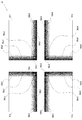
従来より、ひとつの映像(または画像)を複数のプロジェクタを用いて表示するビデオウォール機能とよばれる技術があり、例えば、複数のプロジェクタをマトリクス状に設置して一つの大きな画面とする。図14は、4台のプロジェクタを上下左右に配置した「2×2」のビデオウォール投影を示している。このような表示をするためには、映像の調整が必要になる。そのため、プロジェクタは、色合い、輝度、コントラスト等をユーザが調整できるようになっている。この映像調整として、一般的には、所定のメニュー画面を表示させて、テストパターンなどを投影させながら、目視により調整が行われている。 Conventionally, there is a technique called a video wall function for displaying one video (or image) using a plurality of projectors. For example, a plurality of projectors are installed in a matrix to form one large screen. FIG. 14 shows a “2 × 2” video wall projection in which four projectors are arranged vertically and horizontally. In order to perform such display, it is necessary to adjust the image. Therefore, the projector allows the user to adjust the hue, brightness, contrast, and the like. As the video adjustment, generally, a predetermined menu screen is displayed and a test pattern or the like is projected, and the adjustment is performed visually.
この映像調整において難しい作業のひとつが、隣り合う画面同士の継ぎ目をスムーズにする調整である。よく用いられる手法のひとつに、エッジブレンディングがある。この手法は、各画像間にオーバーラップ領域を設け、オーバーラップ領域における輝度を各画像とオーバーラップ領域との境界を示す重なり開始点からオーバーラップ領域の端部である重なりに向かって徐々に暗くする。 One of the difficult tasks in this image adjustment is to make the joint between adjacent screens smooth. One commonly used technique is edge blending. In this method, an overlap area is provided between images, and the luminance in the overlap area gradually becomes darker from the overlap start point indicating the boundary between each image and the overlap area toward the overlap at the end of the overlap area. To do.
エッジブレンディングが適正に行われない場合、表示される画像が見苦しいものになりかねず、様々な技術が提案されている。例えば、特許文献1に開示の技術では、パーソナルコンピュータに、エッジブレンドボードと呼ばれる画像処理装置を搭載し、プロジェクタからスクリーン上に投射させた映像をカメラで撮影して、プロジェクタを調整している。具体的には、エッジブレンドボードに恒等変換関数を設定し、グラフィックスボード出力の輝度を順次変化させながら、プロジェクタを順番に1台ずつ投射する。そしてスクリーン上の画像をカメラで撮影し、各測定値をプロジェクタとカメラの輝度感度特性として求め、各輝度感度特性を基に各プロジェクタ間の輝度の差を零に補正するための輝度補正値を求める。さらに、この輝度補正値にしたがって基準輝度変換関数を補正して各エッジブレンドボード固有の輝度変換関数を設定し、輝度変換関数にしたがって輝度の補正された画像をスクリーンに連続して並べて表示する。このような処理を行うことで、画像の継ぎ目をスムーズに表示している。
ところで、特許文献1に開示の技術では、専用の映像処理装置と、さらにエッジの境界の輝度を測定するカメラ等の測定装置を搭載したシステムが必要とされた。その結果、自動調整は可能であるものの、システムが大がかりになったり、コストが高くなったり、設置性の観点から導入が難しいケースがあるなどの課題があり、簡易的な且つ低コストのシステムが求められていた。
By the way, the technique disclosed in
本発明の目的は、以上のような状況に鑑みなされたものであって、複数のプロジェクタを用いてひとつの画面を表示することを、簡易的かつ低コストで可能とする技術を提供することにある。 An object of the present invention has been made in view of the above situation, and provides a technique that enables simple and low-cost display of a single screen using a plurality of projectors. is there.
本発明に係る装置は、プロジェクタに関する。このプロジェクタは、複数の投影映像をあわせてひとつの映像を表示するときに、他のプロジェクタが表示する投影映像と重複させる重複領域の輝度をOSD(On Screen Display)によって調整する重複領域生成手段を備える。
また、前記重複領域生成手段は、前記重複領域に前記投影映像を適正に重複させるためのガイドを表示させてもよい。
また、前記投影映像の投影形状をキーストン補正するキーストン補正手段を備えてもよい。
また、前記投影映像が表示された状態を取得する撮像手段を備え、前記キーストン補正手段は、前記撮像手段が取得した前記投影映像の状態をもとに、キーストン補正を行ってもよい。
また、他のプロジェクタと通信を行う通信手段と、前記通信手段を介して他のプロジェクタと複数の前記投影映像をあわせてひとつの映像を表示させる処理を実行する制御手段とを備えてもよい。
本発明の別の態様は、プロジェクタの表示調整方法に関する。この方法は、ビデオウォール表示を行うために、表示すべき映像を生成するビデオウォール画像生成工程と、前記表示すべき映像において、他の映像と重複させるエッジブレンディング領域の輝度を、他の映像と重複したときに本来の輝度になるようにOSD処理により調整するエッジブレンディング領域生成工程と、を備える。
また、前記エッジブレンディング領域に、他の映像と適正に重複させるためのガイドをOSD表示するガイド表示工程を備えてもよい。
The apparatus according to the present invention relates to a projector. This projector includes an overlapping area generating means for adjusting the brightness of an overlapping area to be overlapped with a projected image displayed by another projector by OSD (On Screen Display) when displaying a single image by combining a plurality of projected images. Prepare.
Further, the overlapping area generating unit may display a guide for appropriately overlapping the projection video in the overlapping area.
Further, keystone correction means for performing keystone correction on the projected shape of the projected image may be provided.
In addition, an imaging unit that acquires a state where the projection image is displayed may be provided, and the keystone correction unit may perform keystone correction based on the state of the projection image acquired by the imaging unit.
In addition, a communication unit that communicates with another projector, and a control unit that executes a process of displaying one image by combining the other projector and the plurality of projection images via the communication unit may be provided.
Another aspect of the present invention relates to a display adjustment method for a projector. In this method, in order to perform video wall display, a video wall image generation step for generating a video to be displayed, and a brightness of an edge blending area to be overlapped with another video in the video to be displayed, An edge blending region generating step of adjusting by OSD processing so that the original luminance is obtained when overlapping.
Further, a guide display step for OSD displaying a guide for appropriately overlapping with other images in the edge blending area may be provided.
本発明によれば、複数のプロジェクタを用いてひとつの画面を表示することを、簡易的かつ低コストで可能とする技術を提供することができる。 ADVANTAGE OF THE INVENTION According to this invention, the technique which enables simple and low-cost to display one screen using a some projector can be provided.
次に、本発明を実施するための最良の形態(以下、単に「実施形態」という)を、図面を参照して具体的に説明する。本実施形態において説明するプロジェクタの特徴の概要は以下の通りである。
1)エッジ画素の位置合わせに4点キーストン補正機能を用いる。これにより本体の厳密な位置合わせを簡易化する。
2)ブレンディング手段として、専用IC(Integrated Circuit)ではなくプロジェクタに積まれている画像処理ICのOSD機能を用い、専用ICと同等の機能を実現する。
3)ガイド用マーカー(調整用十字ガイド)をそのブレンディング用OSD機能によって表示させることで1ドット単位の表示位置調整とブレンディングの調整を併せる。
これら3つの機能を組み合わせることにより、ビデオウォールの設置調整の大幅な簡略化を図る。
Next, the best mode for carrying out the present invention (hereinafter simply referred to as “embodiment”) will be specifically described with reference to the drawings. The outline of the features of the projector described in this embodiment is as follows.
1) A 4-point keystone correction function is used for edge pixel alignment. This simplifies exact alignment of the body.
2) As blending means, an OSD function of an image processing IC loaded in a projector is used instead of a dedicated IC (Integrated Circuit), and functions equivalent to those of the dedicated IC are realized.
3) Display guides (adjustment cross guides) are displayed by the blending OSD function, thereby adjusting the display position in units of one dot and blending.
By combining these three functions, the video wall installation adjustment will be greatly simplified.
<第1の実施形態>
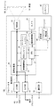
図1は、本実施形態に係るプロジェクタ10の構成を示す機能ブロック図であり、主に画像処理機能に着目して示している。プロジェクタ10は、入力部12と、出力部14と、画像処理部20と、投影部30と、操作部40と、通信部50とを備える。
<First Embodiment>
FIG. 1 is a functional block diagram showing a configuration of the
入力部12は、PC(Personal computer)やDVD(Digital Versatile Disk)プレーヤ等の外部の装置から映像信号を取得する。入力部12は、例えばHDMI(High-Definition Multimedia Interface )やD−subインタフェイスである。出力部14は、映像信号を出力するインタフェイスであり、上述同様HDMIやD−subインタフェイスなどである。
The
画像処理部20は、CPU21と、映像調整部23と、OSDエンジン24と、キーストンエンジン25と、を備え、入力部12から取得した映像信号を所定の形式に変換したり、調整したりして、投影部30に出力する。OSDエンジン24と、キーストンエンジン25とは、それぞれ専用ICにより構成されている。
The
CPU21は、図示しないメモリとともに、所定のプログラムを実行して、映像調整部23と、OSDエンジン24と、キーストンエンジン25とを統括的に制御したり、それら各要素の機能を実行する。また、CPU21は、入力部12や出力部14の入出力制御を行ったり、通信部50の通信制御を行ったり、投影部30による表示出力制御を行ったり、さらに、操作部40に対するユーザの操作を取得し、各構成要素に対して所望の動作を行うように制御する。
The
映像調整部23は、入力部12で取得された映像信号に基づいて、所定の解像度に合わせたスケーリング処理や、輝度調整や、色調整など各種の画像処理を実行する。また、映像調整部23は、ビデオウォール表示を行うときに、上記の映像信号から投影すべき分割映像を作り出す。
Based on the video signal acquired by the
OSDエンジン24は、必要に応じてOSD画面を生成して映像信号に合成する。例えば、OSDエンジン24は、プロジェクタ10の設定画面や、警告などの映像を形成する。また、詳細は後述するが、OSDエンジン24は、エッジブレンディングを行うときに、図3(c)で後述するような重複領域の輝度調整処理を実行したり、ガイド用のマーカーとして調整用十字ガイドを重複領域に表示する。なお、OSDエンジン24の各処理は、公知の技術を用いることで実現できる。例えば、OSDエンジンとして市場で一般的に入手可能なICでは、RGB各色4ビット(計4,096色)の表現ができ、さらに色のついた半透明色を表示するブレンド機能も備える。また、OSD表示と映像とを様々な混合比で合成して透明度合いを制御することもでき、この透明度合いの制御によって輝度制御ができる。
The
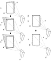
キーストンエンジン25は、キーストン補正を行う。4点補正による一般的なキーストン補正について、図2を基に簡単に説明する。一般に、プロジェクタ10とスクリーン90の相対位置関係により、スクリーンに表示される映像91が台形に歪むことがあり、この歪みをキーストンという。そして、台形歪みを補正することをキーストン補正という。キーストン補正の手順としては、例えば図示のように、まずスクリーン90上の映像91の左上の角を所望の位置に設定し(図2(a))、次に、右上の角(図2(b))、つづいて右下の角(図2(c))、最後に左下の角(図2(e))をそれぞれ所望の位置に設定する。このような手順によって、スクリーン90上には、適正な映像91(図2(e))が表示される。この補正処理は、手動で行う場合と、自動で行う場合とがある。本実施形態では、手動による補正処理について説明し、第2の実施形態においてカメラで撮影しつつ自動的に調整する態様について後述する。
The
図1の説明に戻る。投影部30は、ランプユニットや、液晶パネルやDMDチップなどの所定の光変調手段と、投射用レンズ等の光学ユニットを備えており、CPU21による制御によって画像処理部20から出力された映像信号をスクリーン90に投射する。
Returning to the description of FIG. The
操作部40は、プロジェクタ10に対するユーザからの操作指示を取得する。その指示取得は、プロジェクタ10に設けられた操作パネル(図示せず)から直接取得されてもよいし、操作部40が備えるリモコン受光部41がリモコン42からの指示を取得してもよい。取得した操作指示は、画像処理部20のCPU21に送られる。
The
以上の構成のプロジェクタ10により、ビデオウォール表示をするときのエッジブレンディング処理について説明する。ここでは、まず、図3に示すような、左右に二つの映像を並べてひとつの映像に結合する「2×1」のビデオウォール設定のケースについて説明する。以下便宜的に、左右の各映像を「分割画像」、ひとつに結合された映像91を「結合画像91」ともいう。図4に示す拡大図のように、調整用十字ガイド(96a,96b,97a,97b)を表示して、対応するガイド同士が一致した場合に、分割画像の重複部分が適正な輝度及び色表示となるように調整する。
An edge blending process when displaying a video wall by the
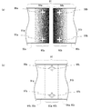
まず、図3(a)に示すように、結合画像91として表示すべき映像は、左側の第1の分割画像91aと右側の第2の分割画像91bとの二つの画像からなる。そして、この左右に並ぶ二つの画像(91a,91b)を結合することで、図3(b)に示す結合された結合画像91がスクリーン90上に表示される。その結合のときに、二つの画像が重複する領域(ブレンディング部93a,93b)が設けられる。
First, as shown in FIG. 3A, the video to be displayed as the combined
第1の分割画像91aにおいては、右端の所定の幅がブレンディング部93aとして設定される。同様に、第2の分割画像91bにおいて、左端の所定の幅がブレンディング部93bとして設定される。二つのブレンディング部93a,93bは同じ幅であり、この領域には同じ映像が表示され、内側から外側へ向けて、比例して輝度が減少する。図3(c)は、OSDエンジン24によって形成される二つのブレンディング部93a,93bの輝度の勾配を示した図である。図示のように、第1の分割画像91aのブレンディング部93aでは、開始部95aにおいて輝度の倍率が100%であり、右端部94aに向かって線形的に減少し、右端部94aで0%となる。同様に、第2の分割画像91bのブレンディング部93bでは、開始部95bにおいて輝度の倍率が100%であり、左端部94bに向かって線形的に減少し、左端部94bで0%となる。そして、二つのブレンディング部93a,93bが適正に一致している場合、各位置における輝度の倍率は100%に合成される。なお、開始部95a,95bや右端部94a及び左端部94bの輝度は、上記の倍率(%)に限るものでない。また、輝度の勾配は、線形に限る趣旨ではなく、合成したときに100%の輝度になればよい。また、輝度の勾配が、映像が表示される対象に応じて設定可能であってもよい。例えば、スクリーン90の種類が変わったときや、スクリーン90の代わりにホワイトボードや黒板が利用されるときに、適切な設定が選択可能とする。
In the first divided
そして、図4(a)に示すように、第1の分割画像91aのブレンディング部93aでは、幅方向中央部分に、上端から所定の位置に上部ガイド96aが、下端から所定の位置に下部ガイド97aが表示される。同様に、第2の分割画像91bのブレンディング部93bでは、幅方向中央部分に、上端から所定の位置に上部ガイド96bが、下端から所定の位置に下部ガイド97bが表示される。上記の所定の位置は、結合される本来1つである結合画像91の大きさにもとづいて自動的に定まってもよいし、ユーザが設定可能となっていてもよい。
Then, as shown in FIG. 4A, in the blending
つづいて、図4(b)に示すように、二つのブレンディング部93a,93bを一致させるときに、左右の上部ガイド96a,96bが一致し、同じく左右の下部ガイド97a,97bが一致すると、二つのブレンディング部93a,93bが完全に一致することになる。そして、二つのブレンディング部93a,93bが完全に一致するときに、第1の分割画像91aのブレンディング部93aの右端部94aと、第2の分割画像91bのブレンディング部93bの開始部95bが一致する。同様に、第2の分割画像91bのブレンディング部93bの左端部94bと、第1の分割画像91aのブレンディング部93aの開始部95aとが一致する。このとき、重複する領域(ブレンディング部93a,93b)の輝度は、図3(c)で説明したように、本来表示するべき輝度として表示される。
Next, as shown in FIG. 4B, when the two blending
なお、ブレンディング部93a,93bの映像は、上述したように、OSDエンジン24により合成して作られる。ここでエッジブレンディング用の輝度合わせ手段にOSDを用いたグラデーションを用いる、つまりOSDエンジン24として用いられるOSD用のICを利用することで、専用ICを削減することができる。さらにOSDを用いている為、輝度の中央点が明確に分かる。そして上述のように、ここに調整用十字ガイド(上部ガイド96a,96b、下部ガイド97a,97b)を表示し、このガイドが左右のプロジェクタ10のガイドと重なるように4点キーストン補正を行うことで隣り合う画像とエッジブレンディングがなされる。
Note that the images of the blending
図5〜7に示すフローチャートに基づいて設定手順を説明する。
図5のフローチャートに示すように、まず、ユーザは二つのプロジェクタ10を左右に並べる(S10)。ここで、スクリーン90に向かって左側に並べられたプロジェクタ10をセット1、右側に並べられたプロジェクタ10をセット2と呼ぶ。
The setting procedure will be described based on the flowcharts shown in FIGS.
As shown in the flowchart of FIG. 5, first, the user arranges the two
つぎに、ユーザは、セット1及びセット2の各操作部40(またはリモコン42)を操作し、ビデオウォール設定画面を呼び出し、「2×1」のビデオウォール設定を行う(S12)。より具体的には、セット1が第1の分割画像91aを表示し、セット2が第2の分割画像91bを表示するように設定がなされる。
Next, the user operates each operation unit 40 (or the remote controller 42) of the
つづいて、ユーザがエッジブレンディング調整モードを呼び出すと、OSDエンジン24はブレンディング部93a,93bをOSDにより所定の輝度に調整する(S14)。さらに、OSDエンジン24は、調整用十字ガイド(上部ガイド96a,96b、下部ガイド97a,97b)をOSD表示させる(S16)。ここで上部ガイド96a,96b、下部ガイド97a,97bは、同一形状及び同一大きさである。
Subsequently, when the user calls the edge blending adjustment mode, the
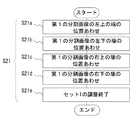
そして、ユーザは、スクリーン90に合い、かつ第1の分割画像91aと第2の分割画像91bの投影領域が重なるようにセット1とセット2との向きを設定し、セット1及びセット2の投影する映像の調整を行う(S20)。ここで、S20の処理では、まずセット1の投影映像が調整され(S21)、つづいて、セット1の投影映像を基準とし、セット2の投影映像が調整される(S22)。
Then, the user sets the orientation of the
図6に示すフローチャートをもとに、セット1の投影映像の調整(S21)について説明する。まず、ユーザは、投影映像である第1の分割画像91aの左上をスクリーン90の左上の端に合わせる(S21a)。つぎに、第1の分割画像91aの左下をスクリーン90の左下の端に合わせる(S21b)。つづいて、第1の分割画像91aの右上をスクリーン90の上辺に合わせる(S21c)。最後に、第1の分割画像91aの右下をスクリーン90の下辺に合わせる(S21d)。以上の操作により、基準となるセット1の調整が終了する(S21e)。なお、ここで、第1の分割画像91aの表示調整のための基準にスクリーン90の左右の端や上下辺を用いたが、これに限る趣旨でない。
Based on the flowchart shown in FIG. 6, the adjustment (S21) of the projected image of the
つぎに図7に示すフローチャートをもとに、セット2の投影映像の調整を説明する(S22)。まず、ユーザは、第2の分割画像91bの右上をスクリーン90の右上の端に合わせる(S22a)。つぎに、第2の分割画像91bの右下をスクリーン90の右下の端に合わせる(S22b)。つづいて、第2の分割画像91bの左上をスクリーン90の上辺に合わせる(S22c)。最後に、第2の分割画像91bの左下をスクリーン90の下辺に合わせる(S22d)。上記S22a〜S22dの処理において、第1の分割画像91aの上部ガイド96aと第2の分割画像91bの上部ガイド96bとが一致し、第1の分割画像91aの下部ガイド97aと第2の分割画像91bの下部ガイド97bとが一致するように調整がなされる。上述したように、上部ガイド96a,96b及び下部ガイド97a,97bは同一形状及び同一大きさなので、第1の分割画像91aと第2の分割画像91bとがそれぞれ適正な形状に調整されていれば、画素1ドットの精度であわせ込むことができるので、実質完全に一致させることができる。したがって、完全に一致していない場合、第1の分割画像91aの右上及び右下と、第2の分割画像91bの左上及び左下の位置を微調整する(S22e)。これにより、第1の分割画像91aと第2の分割画像91bとの重複部分は、重複された状態で、本来表示されるべき輝度になる。以上の操作により、セット2の調整が終了する(S22f)。
Next, the adjustment of the projection image of the set 2 will be described based on the flowchart shown in FIG. 7 (S22). First, the user aligns the upper right of the second divided
上記のS22fの処理によって、セット調整(S20)が終了するので、ユーザは、エッジブレンディング調整モードを終了させて、調整用十字ガイドのOSD表示を終了させる(図5:S30)。これによって、ビデオウォール設定が終了する。 Since the set adjustment (S20) is completed by the process of S22f, the user ends the edge blending adjustment mode and ends the OSD display of the adjustment cross guide (FIG. 5: S30). This completes the video wall setting.
以上本実施形態によれば、簡易かつ高精度にビデオウォールのエッジ合わせを行うことが可能となる。特に、キーストン補正を用いたエッジブレンディングは1ドット単位で二つの表示画面を合わせられる為、高い精度で合わせられる。また、エッジブレンディングでは、端部に向かうにしたがって輝度が減少するため、端部の位置の把握が難しいことがある。しかし、調整用十字ガイドをOSD表示させるので、ユーザは、一致させる領域(ブレンディング部93a,93b)の把握が容易となる。したがって、エッジブレンディングの輝度調整も従来技術で示したような高価な調整装置を用いなくても同時に調整することが可能となる。また、プロジェクタ100や設置用冶具を動かさずに合わせられる為、ユーザは、実際の投影映像の目の前、つまりスクリーン90の傍に立ってリモコン42を用いた調整が可能であり、操作が非常に容易である。また、OSDでエッジをブレンディングする別の利点として、ブレンド幅の設定変更が容易であることが上げられる。例えば、投影映像の大きさや、設置方法などで十分な精度が得られる場合はブレンド幅を狭くして、表示領域を拡大することができる。
As described above, according to the present embodiment, it is possible to perform edge alignment of the video wall easily and with high accuracy. In particular, edge blending using keystone correction can be performed with high accuracy because two display screens can be combined in units of one dot. Also, in edge blending, the luminance decreases as it goes to the end, so it may be difficult to grasp the position of the end. However, since the adjustment cross guide is displayed in OSD, the user can easily grasp the matching areas (blending
なお、本実施形態では、セット1及びセット2それぞれの処理は独立してなされたが、これに限る趣旨ではない。例えば、セット1及びセット2とが各通信部50により接続され、セット1がセット2の処理を制御するようにしてもよい。つまり、ユーザはセット1をマスターとし、セット2をスレーブとして、マスターであるセット1を介してセット2を操作できるようにする。なお、上述の第1及び第2の分割画像91a,91bの位置あわせのときに、OSDエンジン24はエッジブレンディング処理を行わず、調整用十字ガイドの表示の処理のみを行い、セット調整が終了した時点で、エッジブレンディング処理を行ってもよい。このようにすると、位置あわせ作業において、第1及び第2の分割画像91a,91bの端部(境界)の把握が容易となる。
In the present embodiment, the processing of each of the
<第2の実施形態>
本実施形態では、第1の実施形態において、手動で行ったセット1の調整処理(S21)及びセット2の調整処理(S22)を、カメラ31でスクリーン90を撮影することで、自動調整する。なお、本実施形態ではセット1〜4の4台のプロジェクタ100a〜100dによる2×2のビデオウォール表示を行う。なお、セット1〜4の4台のプロジェクタを区別しないときには、「プロジェクタ100」と称する。
<Second Embodiment>
In this embodiment, the adjustment process (S21) of
図8は、本実施の形態に係るプロジェクタ100の機能ブロック図である。第1の実施形態のプロジェクタ10と異なる構成について説明し、同一機能の構成については同一符号を付して説明を省略する。
FIG. 8 is a functional block diagram of
このプロジェクタ100において異なる構成は、スクリーン90に表示された映像を撮影するカメラ31と、その映像をもとにキーストンエンジン25と協働してキーストン補正を行う撮影制御部32とを備えることにある。ここでは、撮影制御部32は画像処理部20に備わる。
The
そして、本実施形態では、図9に示すように、図8に示した構成の4台のプロジェクタ100a〜100dを用いて、スクリーン90に「2×2」のビデオウォールによる表示がなされる。ここで、スクリーン90の領域を2×2に分割したときに、左上の領域を第1の分割領域90e、右上の領域を第2の分割領域90f、左下の領域を第3の分割領域90g、右下の領域を第4の分割領域90hと呼ぶ。そして、スクリーン90左上の第1の分割領域90eには第1の分割画像91eが、右上の第2の分割領域90fには第2の分割画像91fが、左下の第3の分割領域90gには第3の分割画像91gが、右下の第4の分割領域90hには第4の分割画像91hの4つの画像が表示される。そして、第1〜第4の分割画像91a〜91dが適正位置で結合して結合画像91が適正に表示される。ここで、第1の分割画像91eを表示するプロジェクタ100aをセット1、第2の分割画像91fを表示するプロジェクタ100bをセット2、第3の分割画像91gを表示するプロジェクタ100cをセット3、第4の分割画像91hを表示するプロジェクタ100dをセット4と便宜的に呼ぶ。また、画像処理部20の構成については、省略して示している。
In this embodiment, as shown in FIG. 9, display using a “2 × 2” video wall is performed on the
また、図10は、エッジブレンディング調整モードにおいて、結合画像91を構成する第1〜第4の分割画像91e〜91hを分離した状態で模式的に示した図である。図示のように、第1〜第4の分割画像91e〜91hのそれぞれには、以下に詳述すように重複領域において、第1〜第3のガイド98a〜98cの3個の調整用十字ガイドが表示される。
FIG. 10 is a diagram schematically showing the first to fourth divided
より具体的には、第1の分割画像91eは、右辺近傍に所定の幅で鉛直方向に延びる第1のブレンディング部99a1と、下辺近傍に所定の幅で水平方向に延びる第2のブレンディング部99b1と、右下端部において第1のブレンディング部99a1と第2のブレンディング部99b1とがそれぞれ延長したときに重なる領域の第3のブレンディング部99c1とから構成される。そして、第1のブレンディング部99a1の上側部分には第1のガイド98a1が表示され、第2のブレンディング部99b1の左側部分には第2のガイド98b1が表示され、第3のブレンディング部99c1の中央には第3のガイド98c1が表示される。
More specifically, the first divided
同様に、第2の分割画像91fは、左辺近傍に所定の幅で鉛直方向に延びる第1のブレンディング部99a2と、下辺近傍に所定の幅で水平方向に延びる第2のブレンディング部99b2と、左下端部において第1のブレンディング部99a2と第2のブレンディング部99b2とがそれぞれ延長したときに重なる領域の第3のブレンディング部99c2とから構成される。そして、第1のブレンディング部99a2の上側部分には第1のガイド98a2が表示され、第2のブレンディング部99b2の右側部分には第2のガイド98b2が表示され、第3のブレンディング部99c2の中央には第3のガイド98c2が表示される。
Similarly, the second divided
同様に、第3の分割画像91gは、右辺近傍に所定の幅で鉛直方向に延びる第1のブレンディング部99a3と、上辺近傍に所定の幅で水平方向に延びる第2のブレンディング部99b3と、右上端部において第1のブレンディング部99a3と第2のブレンディング部99b3とがそれぞれ延長したときに重なる領域の第3のブレンディング部99c3とから構成される。そして、第1のブレンディング部99a3の下側部分には第1のガイド98a3が表示され、第2のブレンディング部99b3の左側部分には第2のガイド98b3が表示され、第3のブレンディング部99c3の中央には第3のガイド98c3が表示される。
Similarly, the third divided
同様に、第4の分割画像91hは、左辺近傍に所定の幅で鉛直方向に延びる第1のブレンディング部99a4と、上辺近傍に所定の幅で水平方向に延びる第2のブレンディング部99b4と、左上端部において第1のブレンディング部99a4と第2のブレンディング部99b4がとがそれぞれ延長したときに重なる領域の第3のブレンディング部99c4とから構成される。そして、第1のブレンディング部99a4の下側部分には第1のガイド98a4が表示され、第2のブレンディング部99b4の右側部分には第2のガイド98b4が表示され、第3のブレンディング部99c4の中央には第3のガイド98c4が表示される。
Similarly, the fourth divided
そして、第1〜第4の分割画像91e〜91hを結合するときには、第1〜第4の分割画像91e〜91hの各第3のガイド98c1〜98c4が、結合画像91が形成されたときに中央となる位置で一致する。また、中央上部において、第1の分割画像91eの第1のガイド98a1と、第2の分割画像91fの第1のガイド98a2が一致する。さらに、中央左側において、第1の分割画像91eの第2のガイド98b1と、第3の分割画像91gの第2のガイド98b3が一致する。さらにまた、中央下部において、第3の分割画像91gの第1のガイド98a3と第4の分割画像91hの第1のガイド98a4が一致する。そして、中央右側において、第2の分割画像91fの第2のガイド98b2と第4の分割画像91hの第2のガイド98b4が一致する。
When the first to fourth divided
このようなビデオウォール表示を実現するために、図9に示すように、4台のプロジェクタ100は、各通信部50及びネットワークハブ84を介して互いに接続され、1台のプロジェクタ100a(セット1)をマスターとして、他の3台のプロジェクタ100b〜100dを制御して、ビデオウォール設定を実行する。なお、ネットワーク接続されたPC(図示せず)が4台のプロジェクタ100a〜100dを制御する構成であってもよい。
In order to realize such a video wall display, as shown in FIG. 9, the four
上述の構成によるビデオウォール設定の処理について説明する。図11は、本実施形態におけるビデオウォール設定の処理を示すフローチャートである。このフローチャートでは、図5に示したフローチャートとほぼ同じフローであるので、類似する処理には同じ符号を付している。 The video wall setting process with the above configuration will be described. FIG. 11 is a flowchart showing a video wall setting process in the present embodiment. In this flowchart, since the flow is almost the same as the flowchart shown in FIG.
まず、ユーザは4台のプロジェクタ100a〜100dを2×2の縦横各2列に並べる(S10)。
First, the user arranges the four
つぎに、ユーザは、セット1のプロジェクタ100aの操作部40を操作して、ビデオウォール設定画面を呼び出し、上述した配置による「2×2」のビデオウォール設定を行う(S12)。
Next, the user operates the
そして、ユーザから操作部40の操作によりエッジブレンディング調整モードが選択されると、OSDエンジン24は重複領域をOSDにより輝度調整するとともに(S14)、調整用十字ガイドをOSD表示させる(S16)。
When the edge blending adjustment mode is selected by the operation of the
そして、セット1のプロジェクタ100aは、カメラ31でスクリーン90を撮影して、その撮影した映像をもとに4点補正によるキーストン補正を行って、適正な形状になるように各プロジェクタ10の投影映像を調整する(S20)。なお、ここでは、キーストン補正の際の基準として、カメラ31が撮影したスクリーン90の形状とする。撮影されたスクリーン90をもとに、キーストンエンジン25は、重複領域を考慮してスクリーン90を第1〜第4の分割領域90e〜90hに分割設定し、第1〜第4の分割画像91e〜91hの表示すべきスクリーン90上の位置を算出する。算出された各位置として、各第1〜第4の分割画像91e〜91hの各頂点が例示できる。それらは、カメラ31が撮影したスクリーン90や、第1〜第4の分割領域90e〜90hの頂点などの特徴点の位置は,撮影制御部32に記憶され、各セットのビデオウォール設定処理に使用される。
The
第1の実施形態の図6に示したフローチャートと同様な処理をもとに、セット1の投影映像の調整(S21)について説明する。まず、キーストンエンジン25は、撮影制御部32を介して得られるカメラ31の撮影画像をもとに第1の分割画像91eの左上をスクリーン90の第1の分割領域90eの左上の端に合わせる(S21a)。つぎに、キーストンエンジン25は、第1の分割画像91eの左下を、第1の分割領域90eの左下端部に合わせ(S21b)、つづいて、第1の分割画像91eの右上を第1の分割領域90eの右上の端部に合わせる(S21c)。最後に、キーストンエンジン25は、第1の分割画像91eの右下を、第1の分割領域90eの右下の端部に合わせる(S21d)。以上の操作により、基準となるセット1の調整が終了する(S21e)。
The adjustment (S21) of the projected image of the
セット1の調整が終了すると、第1の実施形態の図7に示したフローチャートと同様な処理、セット2の調整が開始する(S22)。キーストンエンジン25は、カメラ31が撮影する映像を参照しながら第2の分割画像91fの右上をスクリーン90の第2の分割領域90fの右上の端に合わせる(S22a)。つぎに、キーストンエンジン25は、第2の分割画像91fの右下を第2の分割領域90fの右下の端に合わせ(S22b)、つづいて、第2の分割画像91fの左上を第2の分割領域90fの左上の端に合わせる(S22c)。最後に、キーストンエンジン25は、第2の分割画像91fの左下を、第2の分割領域90fの左下の端に合わせる(S22d)。そして、キーストンエンジン25は、上記S22a〜S22dの処理において、第1の分割画像91eと第2の分割画像91fのそれぞれの第1のガイド98a1,98b2同士、第3のガイド98c1,98c2同士が一致するように、第2の分割画像91fの投影映像を調整する(S22e)。
When the adjustment of the
セット2の調整が終了すると、図12に示すフローチャートにより、セット3の調整が開始する(S23)。キーストンエンジン25は、カメラ31が撮影する映像を参照しながら第3の分割画像91gの左下を第3の分割領域90gの左下の端に合わせる(S23a)。つぎに、キーストンエンジン25は、第3の分割画像91gの左上を第3の分割領域90gの左上の端に合わせ(S23c)、つづいて、第3の分割画像91gの右下を第3の分割領域90gの右下の端に合わせる(S23d)。そして、キーストンエンジン25は、上記S23a〜S23dの処理において、第1の分割画像91eと第3の分割画像91gのそれぞれの第2のガイド98b1,98b3同士、第3のガイド98c1,98c3同士が一致するように、第3の分割画像91gの投影映像を調整する。
When the adjustment of the set 2 is completed, the adjustment of the set 3 is started according to the flowchart shown in FIG. 12 (S23). The
セット3の調整が終了すると、図13に示すフローチャートにより、セット4の調整が開始する(S24)。キーストンエンジン25は、カメラ31が撮影する映像を参照しながら第4の分割画像91hの右下を第4の分割領域90hの右下の端に合わせる(S24a)。つぎに、キーストンエンジン25は、第4の分割画像91hの右上を第4の分割領域90hの右上の端に合わせ(S24c)、つづいて、第4の分割画像91hの左下を第4の分割領域90hの左下の端に合わせる(S24d)。そして、キーストンエンジン25は、上記S24a〜S24dの処理において、第2の分割画像91fと第4の分割画像91hのそれぞれの第2のガイド98b2,98b4同士、第3のガイド98c2,98c4同士が一致するように、第3の分割画像91gの投影映像を調整する。このとき、第1〜第4の分割画像91e〜91hの各第3のガイド98c1〜98c4が全て同位置で一致する。
When the adjustment of the set 3 is completed, the adjustment of the set 4 is started according to the flowchart shown in FIG. 13 (S24). The
以上、本実施形態によると、エッジブレンディング調整モードが選択された場合に、プロジェクタ100に備わるカメラ31がスクリーン90を撮影して、ビデオウォール設定を自動で実行できる。特に、ビデオウォール表示に使用されるプロジェクタ100の数が多い場合の設定において、その設定作業の簡素化が効果的に実現される。
As described above, according to the present embodiment, when the edge blending adjustment mode is selected, the
以上、本発明を実施形態をもとに説明した。この実施形態は例示であり、それらの各構成要素の組み合わせにいろいろな変形例が可能なこと、またそうした変形例も本発明の範囲にあることは当業者に理解されるところである。例えば、上記実施形態では、ビデオウォール表示について説明したが、複数のプロジェクタを使用して同じ映像を同時に同一領域に表示させるスタック表示にも適用できる。 The present invention has been described based on the embodiments. This embodiment is an exemplification, and it will be understood by those skilled in the art that various modifications can be made to combinations of these components, and such modifications are also within the scope of the present invention. For example, the video wall display has been described in the above embodiment, but the present invention can also be applied to a stack display in which a plurality of projectors are used to simultaneously display the same video in the same area.
10,100a〜100d プロジェクタ
12 入力部
14 出力部
20 画像処理部
21 CPU
23 映像調整部
24 OSDエンジン
25 キーストンエンジン
30 投影部
31 カメラ
32 撮影制御部
40 操作部
41 リモコン受光部
42 リモコン
50 通信部
10, 100a to
23
Claims (7)
前記キーストン補正手段は、前記撮像手段が取得した前記投影映像の状態をもとに、キーストン補正を行うことを特徴とする請求項3に記載のプロジェクタ。 Comprising imaging means for acquiring a state in which the projected image is displayed;
The projector according to claim 3, wherein the keystone correction unit performs keystone correction based on the state of the projection image acquired by the imaging unit.
前記通信手段を介して他のプロジェクタと複数の前記投影映像をあわせてひとつの映像を表示させる処理を実行する制御手段と
を備えることを特徴とする請求項1から4までのいずれか一項に記載のプロジェクタ。 Communication means for communicating with other projectors;
5. The apparatus according to claim 1, further comprising: a control unit that executes a process of displaying one image by combining the plurality of projection images with another projector via the communication unit. The projector described.
前記表示すべき映像において、他の映像と重複させるエッジブレンディング領域の輝度を、他の映像と重複したときに本来の輝度になるようにOSD処理により調整するエッジブレンディング領域生成工程と、
を備えることを特徴とするプロジェクタの表示調整方法。 In order to perform video wall display, a video wall image generation process for generating video to be displayed;
In the video to be displayed, an edge blending region generating step of adjusting the brightness of the edge blending region to be overlapped with another video by OSD processing so that the luminance is the original brightness when overlapping with the other video;
A display adjustment method for a projector, comprising:
Priority Applications (1)
| Application Number | Priority Date | Filing Date | Title |
|---|---|---|---|
| JP2008037701A JP2009200613A (en) | 2008-02-19 | 2008-02-19 | Projector and display adjusting method of projector |
Applications Claiming Priority (1)
| Application Number | Priority Date | Filing Date | Title |
|---|---|---|---|
| JP2008037701A JP2009200613A (en) | 2008-02-19 | 2008-02-19 | Projector and display adjusting method of projector |
Publications (1)
| Publication Number | Publication Date |
|---|---|
| JP2009200613A true JP2009200613A (en) | 2009-09-03 |
Family
ID=41143686
Family Applications (1)
| Application Number | Title | Priority Date | Filing Date |
|---|---|---|---|
| JP2008037701A Pending JP2009200613A (en) | 2008-02-19 | 2008-02-19 | Projector and display adjusting method of projector |
Country Status (1)
| Country | Link |
|---|---|
| JP (1) | JP2009200613A (en) |
Cited By (24)
| Publication number | Priority date | Publication date | Assignee | Title |
|---|---|---|---|---|
| JP2011182077A (en) * | 2010-02-26 | 2011-09-15 | Seiko Epson Corp | Correction information calculation device, image processing device, image display system, and image correction method |
| CN102883209A (en) * | 2012-09-21 | 2013-01-16 | 广东威创视讯科技股份有限公司 | OSD processing method and device for splicing wall |
| JP2013088655A (en) * | 2011-10-19 | 2013-05-13 | Tetsuya Akiba | System and method of displaying content |
| CN103517016A (en) * | 2012-06-22 | 2014-01-15 | 精工爱普生株式会社 | Projector, image display system, and method of controlling projector |
| CN103731648A (en) * | 2012-10-12 | 2014-04-16 | 精工爱普生株式会社 | Projector, and black level area setting method for projector |
| JP2014078872A (en) * | 2012-10-11 | 2014-05-01 | Canon Inc | Projector, control method thereof, and image projection system |
| WO2014075565A1 (en) * | 2012-11-15 | 2014-05-22 | 深圳市光峰光电技术有限公司 | Adjustment method, adjustment device, optical machine and screen splicing wall system |
| WO2015008765A1 (en) * | 2013-07-19 | 2015-01-22 | 株式会社Jvcケンウッド | Multi-projector system, projector device, adjustment device and adjustment method, and adjustment program |
| JP2015118282A (en) * | 2013-12-18 | 2015-06-25 | キヤノン株式会社 | Projection type image display device, method for controlling protection type image display device, and program |
| CN104869376A (en) * | 2015-05-18 | 2015-08-26 | 中国科学院自动化研究所 | Multi-image and multi-pixel level geometric correction method for video fusion |
| JP2016133556A (en) * | 2015-01-16 | 2016-07-25 | キヤノン株式会社 | Position adjustment method of projection image and position adjustment device of projection image |
| JP2017017509A (en) * | 2015-06-30 | 2017-01-19 | キヤノン株式会社 | Projection apparatus and projection method |
| US9621861B2 (en) | 2013-11-21 | 2017-04-11 | Panasonic Intellectual Property Management Co., Ltd. | Projection image display system, projection image display method, and projection-type display apparatus |
| EP3163874A1 (en) | 2015-10-29 | 2017-05-03 | Canon Kabushiki Kaisha | Image processing device, control method for image processing device, program, and computer-readable storage medium |
| JP2017092708A (en) * | 2015-11-10 | 2017-05-25 | キヤノン株式会社 | Projection apparatus, projection method, and projection system |
| JP2017102473A (en) * | 2017-01-20 | 2017-06-08 | セイコーエプソン株式会社 | Projector and black level area setting method for the same |
| CN103595926B (en) * | 2012-08-15 | 2017-06-13 | 无锡思朗电子科技有限公司 | A kind of distributed image Fusion Edges processing system |
| JP2017116950A (en) * | 2013-07-19 | 2017-06-29 | 株式会社Jvcケンウッド | Multi-projector system, projector device, adjusting device and adjusting method, and adjusting program |
| JP2017169237A (en) * | 2017-06-14 | 2017-09-21 | キヤノン株式会社 | Projector, control method thereof, program, and storage medium |
| JP2018055109A (en) * | 2017-11-01 | 2018-04-05 | セイコーエプソン株式会社 | Projector, image display system, and control method for projector |
| JP2018113565A (en) * | 2017-01-11 | 2018-07-19 | セイコーエプソン株式会社 | Display device and control method |
| US11062431B2 (en) | 2017-10-27 | 2021-07-13 | Seiko Epson Corporation | Projector, image projection system, and method for controlling projector |
| JPWO2021171907A1 (en) * | 2020-02-26 | 2021-09-02 | ||
| CN115134567A (en) * | 2022-05-19 | 2022-09-30 | 深圳市康帕斯科技发展有限公司 | Projection picture fusion area correction method, projection picture fusion area correction system, projection system, and medium |
Citations (4)
| Publication number | Priority date | Publication date | Assignee | Title |
|---|---|---|---|---|
| JP2001067015A (en) * | 1999-08-31 | 2001-03-16 | Seiko Epson Corp | Projection-type display device, projection-type display system, and its display method |
| JP2002077778A (en) * | 2000-08-30 | 2002-03-15 | Matsushita Electric Ind Co Ltd | Video projector device |
| JP2006279581A (en) * | 2005-03-29 | 2006-10-12 | Seiko Epson Corp | Projector |
| JP2007132984A (en) * | 2005-11-08 | 2007-05-31 | Seiko Epson Corp | Display apparatus, program, information memory medium and on-screen display image display method |
-
2008
- 2008-02-19 JP JP2008037701A patent/JP2009200613A/en active Pending
Patent Citations (4)
| Publication number | Priority date | Publication date | Assignee | Title |
|---|---|---|---|---|
| JP2001067015A (en) * | 1999-08-31 | 2001-03-16 | Seiko Epson Corp | Projection-type display device, projection-type display system, and its display method |
| JP2002077778A (en) * | 2000-08-30 | 2002-03-15 | Matsushita Electric Ind Co Ltd | Video projector device |
| JP2006279581A (en) * | 2005-03-29 | 2006-10-12 | Seiko Epson Corp | Projector |
| JP2007132984A (en) * | 2005-11-08 | 2007-05-31 | Seiko Epson Corp | Display apparatus, program, information memory medium and on-screen display image display method |
Cited By (39)
| Publication number | Priority date | Publication date | Assignee | Title |
|---|---|---|---|---|
| JP2011182077A (en) * | 2010-02-26 | 2011-09-15 | Seiko Epson Corp | Correction information calculation device, image processing device, image display system, and image correction method |
| US8985777B2 (en) | 2011-10-19 | 2015-03-24 | Tetsuya AKIBA | Content display system and method for displaying content |
| JP2013088655A (en) * | 2011-10-19 | 2013-05-13 | Tetsuya Akiba | System and method of displaying content |
| JP2014006357A (en) * | 2012-06-22 | 2014-01-16 | Seiko Epson Corp | Projector, image display system, and control method of the projector |
| CN103517016A (en) * | 2012-06-22 | 2014-01-15 | 精工爱普生株式会社 | Projector, image display system, and method of controlling projector |
| CN103517016B (en) * | 2012-06-22 | 2017-12-01 | 精工爱普生株式会社 | Projector, image display system, the control method of projector |
| CN103595926B (en) * | 2012-08-15 | 2017-06-13 | 无锡思朗电子科技有限公司 | A kind of distributed image Fusion Edges processing system |
| CN102883209A (en) * | 2012-09-21 | 2013-01-16 | 广东威创视讯科技股份有限公司 | OSD processing method and device for splicing wall |
| US9906761B2 (en) | 2012-10-11 | 2018-02-27 | Canon Kabushiki Kaisha | Projector, its control method, and image projection system |
| US20180139427A1 (en) * | 2012-10-11 | 2018-05-17 | Canon Kabushiki Kaisha | Projector, its control method, and image projection system |
| JP2014078872A (en) * | 2012-10-11 | 2014-05-01 | Canon Inc | Projector, control method thereof, and image projection system |
| JP2014081412A (en) * | 2012-10-12 | 2014-05-08 | Seiko Epson Corp | Projector, and projector black level area setting method |
| US10063821B2 (en) | 2012-10-12 | 2018-08-28 | Seiko Epson Corporation | Projector, and black level area setting method for projector |
| CN103731648B (en) * | 2012-10-12 | 2017-04-12 | 精工爱普生株式会社 | Projector, and black level area setting method for projector |
| US20140104581A1 (en) * | 2012-10-12 | 2014-04-17 | Seiko Epson Corporation | Projector, and black level area setting method for projector |
| US9195126B2 (en) * | 2012-10-12 | 2015-11-24 | Seiko Epson Corporation | Projector, and black level area setting method for projector |
| CN103731648A (en) * | 2012-10-12 | 2014-04-16 | 精工爱普生株式会社 | Projector, and black level area setting method for projector |
| WO2014075565A1 (en) * | 2012-11-15 | 2014-05-22 | 深圳市光峰光电技术有限公司 | Adjustment method, adjustment device, optical machine and screen splicing wall system |
| JP2017116950A (en) * | 2013-07-19 | 2017-06-29 | 株式会社Jvcケンウッド | Multi-projector system, projector device, adjusting device and adjusting method, and adjusting program |
| WO2015008765A1 (en) * | 2013-07-19 | 2015-01-22 | 株式会社Jvcケンウッド | Multi-projector system, projector device, adjustment device and adjustment method, and adjustment program |
| JP2015038590A (en) * | 2013-07-19 | 2015-02-26 | 株式会社Jvcケンウッド | Multi-projector system, projector device, adjustment device and adjustment method, and adjustment program |
| US9621861B2 (en) | 2013-11-21 | 2017-04-11 | Panasonic Intellectual Property Management Co., Ltd. | Projection image display system, projection image display method, and projection-type display apparatus |
| JP2015118282A (en) * | 2013-12-18 | 2015-06-25 | キヤノン株式会社 | Projection type image display device, method for controlling protection type image display device, and program |
| JP2016133556A (en) * | 2015-01-16 | 2016-07-25 | キヤノン株式会社 | Position adjustment method of projection image and position adjustment device of projection image |
| CN104869376A (en) * | 2015-05-18 | 2015-08-26 | 中国科学院自动化研究所 | Multi-image and multi-pixel level geometric correction method for video fusion |
| JP2017017509A (en) * | 2015-06-30 | 2017-01-19 | キヤノン株式会社 | Projection apparatus and projection method |
| US10205921B2 (en) | 2015-10-29 | 2019-02-12 | Canon Kabushiki Kaisha | Image processing device, control method for image processing device, and storage medium storing program |
| EP3163874A1 (en) | 2015-10-29 | 2017-05-03 | Canon Kabushiki Kaisha | Image processing device, control method for image processing device, program, and computer-readable storage medium |
| JP2017092708A (en) * | 2015-11-10 | 2017-05-25 | キヤノン株式会社 | Projection apparatus, projection method, and projection system |
| JP2018113565A (en) * | 2017-01-11 | 2018-07-19 | セイコーエプソン株式会社 | Display device and control method |
| JP2017102473A (en) * | 2017-01-20 | 2017-06-08 | セイコーエプソン株式会社 | Projector and black level area setting method for the same |
| JP2017169237A (en) * | 2017-06-14 | 2017-09-21 | キヤノン株式会社 | Projector, control method thereof, program, and storage medium |
| US11062431B2 (en) | 2017-10-27 | 2021-07-13 | Seiko Epson Corporation | Projector, image projection system, and method for controlling projector |
| US11393080B2 (en) | 2017-10-27 | 2022-07-19 | Seiko Epson Corporation | Projector, image projection system, and method for controlling projector |
| JP2018055109A (en) * | 2017-11-01 | 2018-04-05 | セイコーエプソン株式会社 | Projector, image display system, and control method for projector |
| JPWO2021171907A1 (en) * | 2020-02-26 | 2021-09-02 | ||
| WO2021171907A1 (en) * | 2020-02-26 | 2021-09-02 | 富士フイルム株式会社 | Projection device, projection method, and control program |
| CN115134567A (en) * | 2022-05-19 | 2022-09-30 | 深圳市康帕斯科技发展有限公司 | Projection picture fusion area correction method, projection picture fusion area correction system, projection system, and medium |
| CN115134567B (en) * | 2022-05-19 | 2023-07-25 | 深圳市康帕斯科技发展有限公司 | Projection picture fusion zone correction method, system, projection system and medium |
Similar Documents
| Publication | Publication Date | Title |
|---|---|---|
| JP2009200613A (en) | Projector and display adjusting method of projector | |
| US9621861B2 (en) | Projection image display system, projection image display method, and projection-type display apparatus | |
| US6932480B2 (en) | Image processing system, projector, program, information storage medium and image processing method | |
| JP6164820B2 (en) | Projector, control method therefor, and image projection system | |
| CN103559862B (en) | The Subarea calibration method of LED display | |
| US9554105B2 (en) | Projection type image display apparatus and control method therefor | |
| JP5971973B2 (en) | Projection device | |
| US10440337B2 (en) | Projection apparatus, information processing apparatus, and control methods thereof | |
| JP2004336225A (en) | Image processing system, projector, program, information storage medium, and picture processing method | |
| US20080297542A1 (en) | Projector, image display system, and image processing system | |
| US9811876B2 (en) | Display apparatus and control method | |
| US20100117929A1 (en) | Multi-display system, information processor, and image data processing method in multi-display system | |
| EP1385340A2 (en) | Color adjusting method for projector | |
| US20170244941A1 (en) | Projector and control method thereof | |
| JP2011029727A (en) | Image projector | |
| JP2006245737A (en) | Projection image correction device and method for projection image correction and program | |
| JP5205865B2 (en) | Projection image shape distortion correction support system, projection image shape distortion correction support method, projector, and program | |
| US20130335643A1 (en) | Projection-type image display device and light quantity adjustment method | |
| JP2011188404A (en) | Image processing apparatus in multi-projection system, method of processing image in multi-projection system, and multi-projection system | |
| JP2006033672A (en) | Curved surface multi-screen projection method, and its device | |
| JP2011091516A (en) | Projector and display adjustment method of the projector | |
| JP2011135445A (en) | Image projection apparatus | |
| CN112565723B (en) | Image fusion band display control method, device and system | |
| CN112565722B (en) | Fusion zone adjusting method, device and system based on image fusion | |
| JPH06105185A (en) | Brightness correction method |
Legal Events
| Date | Code | Title | Description |
|---|---|---|---|
| A621 | Written request for application examination |
Free format text: JAPANESE INTERMEDIATE CODE: A621 Effective date: 20100218 |
|
| A977 | Report on retrieval |
Free format text: JAPANESE INTERMEDIATE CODE: A971007 Effective date: 20120405 |
|
| A131 | Notification of reasons for refusal |
Free format text: JAPANESE INTERMEDIATE CODE: A131 Effective date: 20120417 |
|
| A02 | Decision of refusal |
Free format text: JAPANESE INTERMEDIATE CODE: A02 Effective date: 20120911 |