JP2006033672A - Curved surface multi-screen projection method, and its device - Google Patents
Curved surface multi-screen projection method, and its device Download PDFInfo
- Publication number
- JP2006033672A JP2006033672A JP2004212667A JP2004212667A JP2006033672A JP 2006033672 A JP2006033672 A JP 2006033672A JP 2004212667 A JP2004212667 A JP 2004212667A JP 2004212667 A JP2004212667 A JP 2004212667A JP 2006033672 A JP2006033672 A JP 2006033672A
- Authority
- JP
- Japan
- Prior art keywords
- image
- divided image
- divided
- images
- luminance
- Prior art date
- Legal status (The legal status is an assumption and is not a legal conclusion. Google has not performed a legal analysis and makes no representation as to the accuracy of the status listed.)
- Pending
Links
Images


Abstract
Description
本発明は、一つの入力画面を複数の画像に分割して曲面形状のスクリーンに投射し、合成された一つの表示画像を形成するプロジェクタ駆動装置および分割画像投射方法に係り、特に複数に分割されて合成表示される画像のつなぎ目を識別できないようにして高品位画像を形成できるようにした曲面マルチスクリーン投射方法及び曲面マルチスクリーン投射装置に関する。 The present invention relates to a projector driving apparatus and a divided image projection method for dividing a single input screen into a plurality of images and projecting them on a curved screen to form a combined display image. In particular, the present invention relates to a curved multi-screen projection method and a curved multi-screen projection apparatus that can form a high-quality image in such a manner that joints of images synthesized and displayed cannot be identified.
近年、ディスプレイの高精細化のニーズは急速に高まってきており、特に大画面表示に適したプロジェクタも開発されている。走査線数が1125本、2000本、4000本のものもある。
一方、明るい場所に設置される高精細プロジェクタの場合では、走査線数が525本程度の標準テレビ方式のプロジェクタを複数用い、輝度が高く高精細なプロジェクション画像を得ている。走査線数の多いプロジェクタは輝度レベルが低いため、輝度レベルの高いプロジェクタを複数用いることにより輝度レベルの高い高精細画像を得ている。
In recent years, the need for high-definition displays has increased rapidly, and projectors suitable for large-screen display have been developed. There are also 1125, 2000, and 4000 scan lines.
On the other hand, in the case of a high-definition projector installed in a bright place, a plurality of standard television projectors having about 525 scanning lines are used to obtain a high-definition projection image with high brightness. Since a projector having a large number of scanning lines has a low luminance level, a high-definition image having a high luminance level is obtained by using a plurality of projectors having a high luminance level.
特許文献1には、1つの画面のアナログ入力画像信号を画像分割回路1に入力して複数の分割画像に分割し、対応する分割画像のアナログ画像信号を複数のプロジェクタを用いてスクリーンに投影して表示する。プロジェクタに設けられた調整手段によりプロジェクタから投射されるそれぞれの分割投影画像の大きさを調整することにより、スクリーンに隣接する境界部で像の重なりや隙間をなく合成表示するマルチスクリーン投射方法が開示されている。
しかしながら、特許文献1のマルチスクリーン投射方法は、平面スクリーンに対して分割画像を画像の重なりや隙間なく投射する方法である。表示される映像も多様化されると共に表示スクリーンも多様化の方向にあり、例えば球状の曲面を有するスクリーンに分割画像を像の重なりや隙間をなくして表示する曲面分割画像投射方法の実現化が望まれている。特許文献1のマルチスクリーン投射方法を曲面のスクリーンに応用する場合は、プロジェクターからスクリーンまでの距離が一定しないため、分割画像の境界部が直線とはならなく、曲面スクリーン上に分割画像を像の重なりや隙間をなくして表示することは出来ない。
However, the multi-screen projection method of
そこで、本発明は、上記のような問題点を解消するためになされたもので、投射スクリーンが曲面を有している場合であっても像の重なりや隙間をなくした分割合成画像を表示することの出来る曲面マルチスクリーン投射方法及び曲面マルチスクリーン投射装置を提供することを目的とする。 Therefore, the present invention has been made to solve the above-described problems, and displays a divided composite image that eliminates image overlap and gaps even when the projection screen has a curved surface. An object of the present invention is to provide a curved multi-screen projection method and a curved multi-screen projection apparatus that can perform the above-described process.
本願発明における第1の発明は、複数の分割画像の一部をオーバラップさせるように合成して1つの画像として曲面上に投映表示する際に、前記複数の分割画像のつなぎ目がなめらかで、かつ輝度が一定な曲面マルチスクリーン投射方法において、前記複数の分割画像の水平方向における配列順を第1分割画像、第2分割画像、第3分割画像とし、垂直方向の配列順を前記第2分割画像、第4分割画像とするとき、第1、第2分割画像のオーバーラップ領域における前記第1分割画像の端から前記第2分割画像の端に向かって前記第1分割画像の輝度を減衰させ、前記第2分割画像の端から前記第1分割画像の端に向かって前記第2分割画像の輝度を減衰させる第1ステップと、前記第2、第3分割画像のオーバーラップ領域における前記第2分割画像の端から前記第3分割画像の端に向かって前記第2分割画像の輝度を減衰させ、前記第3分割画像の端から前記第2分割画像の端に向かって前記第3分割画像の輝度を減衰させる第2ステップと、前記第2、第4分割画像のオーバーラップ領域における前記第2分割画像の端から前記第4分割画像の端に向かって前記第2分割画像の輝度を減衰させ、前記第4分割画像の端から前記第2分割画像の端に向かって前記第4分割画像の輝度を減衰させる第3ステップと、からなるからなることを特徴とする曲面マルチスクリーン投射方法を提供する。
第2の発明は、前記第1の発明において、前記第1ステップの前に前記第1乃至第4分割画像を平面上に投映した際の平面画像領域から前記曲面上に投映した際の曲面画像領域を差し引いた領域を除去することを特徴とする曲面マルチスクリーン投射方法を提供する。
第3の発明は、複数の分割画像の一部をオーバラップさせるように合成して1つの画像として曲面上に投映表示する際に、前記複数の分割画像のつなぎ目がなめらかで、かつ輝度が一定な曲面マルチスクリーン投射装置において、前記複数の分割画像の水平方向における配列順を第1分割画像、第2分割画像、第3分割画像とし、垂直方向の配列順を前記第2分割画像、第4分割画像とするとき、第1、第2分割画像のオーバーラップ領域における前記第1分割画像の端から前記第2分割画像の端に向かって前記第1分割画像の輝度を減衰させ、前記第2分割画像の端から前記第1分割画像の端に向かって前記第2分割画像の輝度を減衰させる第1処理手段と、前記第2、第3分割画像のオーバーラップ領域における前記第2分割画像の端から前記第3分割画像の端に向かって前記第2分割画像の輝度を減衰させ、前記第3分割画像の端から前記第2分割画像の端に向かって前記第3分割画像の輝度を減衰させる第2処理手段と、前記第2、第4分割画像のオーバーラップ領域における前記第2分割画像の端から前記第4分割画像の端に向かって前記第2分割画像の輝度を減衰させ、前記第4分割画像の端から前記第2分割画像の端に向かって前記第4分割画像の輝度を減衰させる第3処理手段と、からなるからなることを特徴とする曲面マルチスクリーン投射装置を提供する。
第4の発明は、前記第3の発明において、前記第1処理手段の前段に、前記第1乃至第4分割画像を平面上に投映した際の平面画像領域から前記曲面上に投映した際の曲面画像領域を差し引いた領域を除去する処理手段を有することを特徴とする曲面マルチスクリーン投射装置を提供する。
According to a first aspect of the present invention, when a part of a plurality of divided images is overlapped and projected as a single image on a curved surface, the joints of the plurality of divided images are smooth, and In the curved multi-screen projection method with constant luminance, the arrangement order in the horizontal direction of the plurality of divided images is a first divided image, a second divided image, and a third divided image, and the arrangement order in the vertical direction is the second divided image. When the fourth divided image is used, the luminance of the first divided image is attenuated from the end of the first divided image toward the end of the second divided image in the overlap region of the first and second divided images, A first step of attenuating the luminance of the second divided image from the end of the second divided image toward the end of the first divided image; and the first step in the overlap region of the second and third divided images. The brightness of the second divided image is attenuated from the edge of the divided image toward the edge of the third divided image, and the edge of the third divided image is extended from the edge of the third divided image toward the edge of the second divided image. A second step of attenuating the brightness, and attenuating the brightness of the second divided image from the edge of the second divided image toward the edge of the fourth divided image in the overlap region of the second and fourth divided images. And a third step of attenuating the luminance of the fourth divided image from the end of the fourth divided image toward the end of the second divided image. To do.
According to a second aspect of the present invention, in the first aspect of the present invention, the curved surface image when the first to fourth divided images are projected onto the curved surface from the planar image region when the first to fourth divided images are projected onto the plane before the first step. There is provided a curved multi-screen projection method characterized by removing an area obtained by subtracting an area.
According to a third aspect of the present invention, when a part of a plurality of divided images are overlapped and projected onto a curved surface as one image, the joints of the plurality of divided images are smooth and the luminance is constant. In such a curved multi-screen projection apparatus, the arrangement order of the plurality of divided images in the horizontal direction is the first divided image, the second divided image, and the third divided image, and the arrangement order in the vertical direction is the second divided image and the fourth divided image. When the divided image is formed, the luminance of the first divided image is attenuated from the end of the first divided image toward the end of the second divided image in the overlap region of the first and second divided images, and the second First processing means for attenuating the brightness of the second divided image from the edge of the divided image toward the edge of the first divided image; and the second divided image in the overlap region of the second and third divided images. End The second divided image is attenuated in luminance toward the edge of the third divided image, and the luminance of the third divided image is attenuated from the edge of the third divided image toward the edge of the second divided image. A second processing unit for attenuating the luminance of the second divided image from the end of the second divided image toward the end of the fourth divided image in the overlap region of the second and fourth divided images, There is provided a curved multi-screen projection device comprising: a third processing unit that attenuates the luminance of the fourth divided image from the edge of the divided image toward the edge of the second divided image.
According to a fourth invention, in the third invention, when the first to fourth divided images are projected on the curved surface from the plane image area when the first to fourth divided images are projected on the plane before the first processing means. There is provided a curved multi-screen projection apparatus having processing means for removing an area obtained by subtracting a curved image area.
本発明によれば、複数の分割画像の一部をオーバラップさせるように合成して1つの画像として曲面上に投映表示する際に、前記複数の分割画像のつなぎ目がなめらかで、かつ輝度が一定な曲面マルチスクリーン投射装置において、前記複数の分割画像の水平方向における配列順を第1分割画像、第2分割画像、第3分割画像とし、垂直方向の配列順を前記第2分割画像、第4分割画像とするとき、第1、第2分割画像のオーバーラップ領域における前記第1分割画像の端から前記第2分割画像の端に向かって前記第1分割画像の輝度を減衰させ、前記第2分割画像の端から前記第1分割画像の端に向かって前記第2分割画像の輝度を減衰させる第1処理手段と、前記第2、第3分割画像のオーバーラップ領域における前記第2分割画像の端から前記第3分割画像の端に向かって前記第2分割画像の輝度を減衰させ、前記第3分割画像の端から前記第2分割画像の端に向かって前記第3分割画像の輝度を減衰させる第2処理手段と、前記第2、第4分割画像のオーバーラップ領域における前記第2分割画像の端から前記第4分割画像の端に向かって前記第2分割画像の輝度を減衰させ、前記第4分割画像の端から前記第2分割画像の端に向かって前記第4分割画像の輝度を減衰させる第3処理手段と、からなる格別な構成があるので、分割した画像を曲面を有するスクリーンに投射し、分割画像の境界部で像の重なりや隙間をなくした分割合成画像を表示することの出来る曲面マルチスクリーン投射方法及び曲面マルチスクリーン投射装置を提供することができる。 According to the present invention, when combining a part of a plurality of divided images so as to be projected and displayed on a curved surface as one image, the joints of the plurality of divided images are smooth and the luminance is constant. In such a curved multi-screen projection apparatus, the arrangement order of the plurality of divided images in the horizontal direction is the first divided image, the second divided image, and the third divided image, and the arrangement order in the vertical direction is the second divided image and the fourth divided image. When the divided image is formed, the luminance of the first divided image is attenuated from the end of the first divided image toward the end of the second divided image in the overlap region of the first and second divided images, and the second First processing means for attenuating the brightness of the second divided image from the edge of the divided image toward the edge of the first divided image; and the second divided image in the overlap region of the second and third divided images. end The luminance of the second divided image is attenuated toward the edge of the third divided image, and the luminance of the third divided image is attenuated from the edge of the third divided image toward the edge of the second divided image. A second processing unit for attenuating the brightness of the second divided image from an end of the second divided image in an overlap region of the second and fourth divided images toward an end of the fourth divided image; Since there is a special configuration comprising third processing means for attenuating the luminance of the fourth divided image from the end of the four-divided image toward the end of the second divided image, the divided image is formed on a screen having a curved surface. It is possible to provide a curved multi-screen projection method and a curved multi-screen projection apparatus that can project and display a divided composite image in which overlapping and gaps of images are eliminated at the boundary between divided images.
以下に本発明の各実施例に係る曲面マルチスクリーン投射方法及び曲面マルチスクリーン投射装置について図1〜図12を用いて説明する。
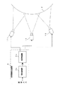
図1は、本発明の実施に係る曲面マルチスクリーン投射システムの概略構成例を示す平面図である。
図2は、本発明の実施例に係る9面マルチ画像を投射するプロジェクタの斜視図である。
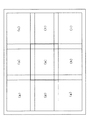
図3は、9面マルチ画像を平面スクリーンに投射した場合の表示例を示す図である。
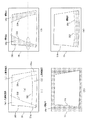
図4は、本発明の実施に係る球面スクリーンに投射した9面マルチ画像の表示例を示す図である。
図5は、本発明の実施例に係る球面スクリーンに投射、表示される画像を拡大した図である。
図6は、本発明の実施に係る分割画像生成装置の概略構成例を示す図である。
図7は、本発明の実施例に係る9面マルチ画像の一部を説明するための図である。
図8は、本発明の実施に係る境界領域のフィルタ特性例を示す図である。
図9は、本発明の実施例に係る境界処理部の要部を示す図である。
図10は、本発明の実施に係る境界処理部の構成例を示す図である。
図11は、本発明の実施に係る境界処理部から出力される9面マルチ画像例を示す図である。
図12は、本発明の実施に係る境界処理部から出力される9面マルチ画像の特性付加の様子を例示する図である。
Hereinafter, a curved multi-screen projection method and a curved multi-screen projection apparatus according to each embodiment of the present invention will be described with reference to FIGS.
FIG. 1 is a plan view showing a schematic configuration example of a curved multi-screen projection system according to an embodiment of the present invention.
FIG. 2 is a perspective view of a projector that projects a nine-plane multi-image according to an embodiment of the present invention.
FIG. 3 is a diagram illustrating a display example when a 9-plane multi-image is projected onto a flat screen.
FIG. 4 is a diagram showing a display example of a 9-plane multi-image projected on the spherical screen according to the embodiment of the present invention.
FIG. 5 is an enlarged view of an image projected and displayed on the spherical screen according to the embodiment of the present invention.
FIG. 6 is a diagram illustrating a schematic configuration example of the divided image generation apparatus according to the embodiment of the present invention.
FIG. 7 is a diagram for explaining a part of the nine-plane multi-image according to the embodiment of the present invention.
FIG. 8 is a diagram illustrating an example of the filter characteristics of the boundary region according to the embodiment of the present invention.
FIG. 9 is a diagram illustrating a main part of the boundary processing unit according to the embodiment of the present invention.
FIG. 10 is a diagram illustrating a configuration example of the boundary processing unit according to the embodiment of the present invention.
FIG. 11 is a diagram illustrating an example of a nine-plane multi-image output from the boundary processing unit according to the embodiment of the present invention.
FIG. 12 is a diagram illustrating a state of adding characteristics of the nine-plane multi-image output from the boundary processing unit according to the embodiment of the present invention.
曲面マルチスクリーン投射システムの構成について述べる。
図1に示す3台のプロジェクタを用いる曲面マルチスクリーン投射システムは、曲面スクリーン2と、幾何変換部3a及び境界処理部3bからなる分割画像生成装置3と、複数のプロジェクタ11〜13より構成される。
図2に示すように、9台のプロジェクタはプロジェクタ(a)11〜プロジェクタ(i)19のように配置される。
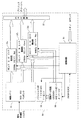
図6に示すように、分割画像生成装置3は、幾何変換部3aと、画像メモリ31、係数データ回路33、制御回路35、境界処理回路36、及び出力分配器37よりなる境界処理部3bとで構成される。
図9に示すように、係数データ回路33は第1特性付加331、第2特性付加332、及び第3特性付加333より構成される。
図10に示すように、境界処理部3bは、画像メモリ31、フラッシュROM32、係数データ回路33、制御回路35、赤、緑、青それぞれの画像信号処理を行う乗算器36a〜36c、及び出力分配器37で構成される。
The configuration of the curved multi-screen projection system will be described.
The curved multi-screen projection system using the three projectors shown in FIG. 1 includes a
As shown in FIG. 2, nine projectors are arranged as projector (a) 11 to projector (i) 19.
As shown in FIG. 6, the divided
As shown in FIG. 9, the
As shown in FIG. 10, the
曲面マルチスクリーン投射システムの動作について述べる。
概要を説明する。
まず、曲面スクリーン2に分割合成して表示する画像信号は分割画像生成装置3の幾何変換部3aに入力される。幾何変換部3aでは、入力される画像信号を複数のプロジェクタにより分割して投影するための複数の画像信号に分割する。分割された画像の境界部で同一の画像が重ね合わされて表示されるように、隣接する分割画像をオーバラップさせる。スクリーンが曲面であるために生じる歪を幾何変換により補正する。曲面スクリーン2に投射される映像はオーバラップ部分の輝度が他よりも明るくなるので、境界処理部3bにより輝度レベルが一定になるように調整する。境界処理部3bから出力されるそれぞれの分割映像信号はそれぞれのプロジェクタに供給され、それらから曲面スクリーン2に投影される。
The operation of the curved multi-screen projection system will be described.
An outline will be described.
First, an image signal to be divided and displayed on the
以下、詳細に説明する。
図2に示す、プロジェクタ(a)11〜プロジェクタ(i)19の設置される9台のプロジェクタを用いて球面に投射するようにして曲面マルチスクリーン投射システムを実現する。
図3は、プロジェクタ(a)11〜プロジェクタ(i)19の9台のプロジェクタで平面スクリーンに投影したときの投射領域である。図中、太線で示す領域はプロジェクタ(e)15により投射される分割画像の領域である。その領域の端部は周囲に配置されるプロジェクタの投射領域と共通部分を有している。同様にして、それぞれのプロジェクタから投射される分割画像は、お互いにオーバラップして投影されるように投射領域が調整され、決められている。
Details will be described below.
A curved multi-screen projection system is realized by projecting onto a spherical surface using nine projectors in which projectors (a) 11 to (i) 19 shown in FIG. 2 are installed.
FIG. 3 shows projection areas when nine projectors, ie, the projector (a) 11 to the projector (i) 19, are projected onto a flat screen. In the drawing, a region indicated by a bold line is a region of a divided image projected by the projector (e) 15. The end of the area has a common part with the projection area of the projector arranged around. Similarly, the divided areas projected from the respective projectors are determined by adjusting the projection areas so that they are projected so as to overlap each other.
図4に示す、曲面スクリーン2に投影する場合の分割画像は、同様に周辺部の画像部分がオーバラップしている。スクリーンが曲面であるためプロジェクタとスクリーン間の距離は一定でないため分割画像の周囲形状は図3のように直線で形成される矩形ではなく、曲線で形成される表示領域になる。幾何変換部3aは、それぞれのプロジェクタと曲面スクリーン2との間の投射距離の差により生じる画像の縮小及び拡大を打ち消すように補正する。9台のプロジェクタのうち、端部の方に配置されるプロジェクタ(a)11、プロジェクタ(c)13、プロジェクタ(g)17、及びプロジェクタ(i)19のそれぞれから曲面スクリーン2に投影される映像は、球面スクリーンであるため表示領域が不足するなどにより、スクリーン上の表示領域を変形させている。幾何変換部3aは、これらの画像の縮小、拡大、及び表示領域の調整を行う。調整された表示領域は、曲面スクリーン2に自然な形状で表示されると共に、境界部では隣接するプロジェクタ同士で共通の画像部分を重ねて表示するように設定する。
In the divided image when projected onto the
図5に示す、図4上部の拡大図で、斜線を施した部分は隣接するプロジェクタ同士の投射画像がオーバラップして表示される部分である。このオーバラップされて表示される部分の輝度レベルは、そのままでは周辺より高いレベルとなる。オーバラップされる部分の輝度レベルを、オーバラップされない周辺画像の輝度レベルと同一になるように減衰させる。
オーバラップされる領域同士が重なり合う、図面で黒く示される領域は、3台以上のプロジェクタから同時に投射される場所である。この領域は、さらにプロジェクタの光量を減衰させ、周囲との輝度差が生じないように輝度レベルを補正する。
In the enlarged view at the top of FIG. 4 shown in FIG. 5, the hatched portion is a portion where the projection images of adjacent projectors are displayed in an overlapping manner. The luminance level of the overlapped portion is higher than the surroundings as it is. The brightness level of the overlapped portion is attenuated to be the same as the brightness level of the non-overlapping surrounding image.
The area shown in black in the drawing where the overlapping areas overlap is a place where three or more projectors project simultaneously. This area further attenuates the light quantity of the projector and corrects the luminance level so that no luminance difference from the surroundings occurs.
図6に示す分割画像生成処理装置3の幾何変換部3aは、入力画像信号をそれぞれのプロジェクタ11〜19から出力する分割画像の輪郭形状を定める。その輪郭形状は分割画像の周辺部に対し、隣接プロジェクタが投射する画像と共通の画像部分を含むようにした形状にする。幾何変換部3aは、その輪郭形状に従って分割した画像を生成し、境界処理部3bの画像メモリ31に入力する。幾何変換部3aからは、分割画像に共通して含まれる画像部分の位置データが係数データ回路33に入力され、そこに一時記憶される。境界処理回路36には画像メモリに一時記憶されている分割画像データと、係数データ回路33に一時記憶された共通な画像部分の位置データが入力される。境界処理回路36は制御回路35からの演算命令に従って、例えばプロジェクタ11からプロジェクタ19の順に、それらのプロジェクタに入力する画像の境界演算処理を行う。演算結果は、制御回路35により出力信号が切り換えられる出力分配器37を介して、プロジェクタ11からプロジェクタ19に順に出力される。
The geometric conversion unit 3a of the divided image
図7に示す輪郭形状211と、共通画像部分であるそれぞれの領域Q、R、及びSに対する境界処理について述べる。
同図において、領域Pは例えばプロジェクタ(b)12が投影可能な領域21と、実際に投影する輪郭形状211との間の領域であり、この領域は黒に表示される領域である。
領域Qは輪郭形状211の左側にある、プロジェクタ(a)と共通の画像部分を表示するための領域線212により囲まれる領域である。同様にして、領域Rはプロジェクタ(e)と共通の画像部分を表示するための領域線213で区切られた領域である。領域Sはプロジェクタ(c)と共通の画像部分を表示するための領域線214により区切られた領域である。
Boundary processing for the
In the figure, a region P is, for example, a region between the
A region Q is a region surrounded by a
これらの領域線を決める方法は、幾何変換部により変換された、例えばプロジェクタ(a)とプロジェクタ(b)の画像を曲面スクリーン2に表示する。表示画像には上下左右に移動可能なヘアラインカーソルを共に表示する。プロジェクタ(a)とプロジェクタ(b)で共通の画像部分が表示される個所にヘアラインカーソルを移動し、その移動地点の画像アドレス値を得るようにして境界線に係るアドレス値を得る。それらの得られたアドレス値の点を結合して境界線の位置情報を得る。同様にして他のプロジェクタとの組み合わせにおける、お互いに共通な画像部分が表示される領域のアドレス値を得る。
As a method for determining these area lines, for example, images of the projector (a) and the projector (b) converted by the geometric conversion unit are displayed on the
次に、図7の(3)に1点鎖線及び丸で囲んだ部分の画像の輝度レベルについて説明する。
図8に示す特性は、共通の画像部分の重ね合わせを行うための輝度レベルの応答特性を示す。実線で示す(b)の応答特性は投影可能領域21から輪郭形状211までは黒レベルであり、輪郭形状211の左側では左方向に徐々に増加し、領域線212の個所及び領域線212の左側では減衰量が0の応答特性となる。図示しない領域線214と輪郭形状211の間では特性は徐々に減衰し、輪郭形状211と投影可能領域21との間は黒レベルとなる。
Next, the luminance level of the image of the part surrounded by the one-dot chain line and the circle in FIG.
The characteristic shown in FIG. 8 shows the response characteristic of the luminance level for superimposing common image portions. The response characteristic of (b) indicated by a solid line is a black level from the
(a)に破線で示す特性は、プロジェクタ(a)により多重表示される部分の応答特性を重ねて示したものである。この部分の曲面スクリーン2におけるプロジェクタ(a)とプロジェクタ(b)とで合成された画像は明るさが一定の値に保たれるようにする。すなわち、輪郭形状211と領域線212との間の距離に対する応答特性は定数がが可変可能なγ特性により与える。輪郭形状211と領域線212との間の輝度レベルを監視しつつγの値を変化させ、この領域の輝度レベルが一定になるγ値を得る。ここで、γ=1の特性は投影可能領域21から輪郭形状211までの輝度変化が直線で変化する特性となる。投影可能領域21と輪郭形状211との中間位置における輝度レベルを、γ値を変化させて周辺と同じ輝度レベルを与えるγ値を選定すれば良い。ガンマの値はプロジェクタの発光素子の特性により変わる。ブラウン管を発光素子に用いるプロジェクタの場合ではγ=2.2程度が良い。
The characteristic indicated by the broken line in (a) is an overlay of the response characteristics of the portion that is displayed in multiple by the projector (a). The brightness of the image synthesized by the projector (a) and the projector (b) on the
領域Qと領域Rとが重なる領域21qrは左側及び下側のプロジェクタから投射される領域である。この領域の輝度は領域Qや領域Rよりもさらに高くなるため、さらに減衰が必要な領域である。
図9に示す係数データ回路33はそのための回路である。即ち、複数のプロジェクタから曲面スクリーン2の同一領域に投射する、それぞれの領域Q、R、及びQRに対して光量を減衰させるための特性付加を与える。即ち、減衰特性を与える係数データは、保存用領域32から得られる領域のアドレスデータに対する平面上の減衰を、まず第1特性付加331により領域Pについて与え、次に第2特性付加332により領域Q及び領域Sについて図8に示す特性に従って与え、最後に第3特性付加333により領域Rに対する減衰量を図8と同様の特性により与える。従って、領域21qrの減衰は第2特性付加332及び第3特性付加333の両者により与えられるため、与えられる減衰量も大きな値となり、4台のプロジェクタから同一の個所に投射される光の重なりによる明るさの増加を他の領域と同一に出来る。
A region 21qr where the region Q and the region R overlap is a region projected from the left and lower projectors. Since the luminance of this region is higher than that of the region Q and the region R, the region needs further attenuation.
The
図10は、図6に示した分割画像生成装置3の境界処理部3bにおける境界処理回路36の構成を更に詳しく示したものである。画像メモリ31からはRGB(赤、緑、青)それぞれが8ビットの画像データとしてそれぞれの乗算器36a〜36cに入力される。乗算器36a〜36cでは、図9に示した係数データ回路33から画像の領域毎に与えるべき2次元の10ビットの減衰データ(平面)が入力される。画像データ(平面)と減衰データとはクロック周波数108MHzで乗算することによりプロジェクタのRGBの入力端子に供給する画像信号が得られる。
FIG. 10 shows in more detail the configuration of the
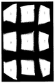
図11は、図7で示した領域の決定を9台のプロジェクタに対して行い得られた領域線の位置(境界)を示す。1点鎖線は次分の左右に配置されるプロジェクタとの共通の表示領域に係る境界である。破線は上下に配置されるプロジェクタとの共通の表示領域に係る境界である。
図12は、上記境界を基に領域毎の減衰特性を演算したものである。白い部分が減衰0の表示領域であり、黒い部分は表示光が出力されない領域である。これらの特性を付加した画像信号を9台のプロジェクタ(a)11〜プロジェクタ(i)19により曲面スクリーン2に投射し、つなぎ目で輝度レベルの変化がなく1つに合成された高精細大画面が得られている。
FIG. 11 shows the position (boundary) of the area line obtained by determining the area shown in FIG. 7 for nine projectors. A one-dot chain line is a boundary related to a display area common to the projectors arranged on the left and right of the next minute. A broken line is a boundary related to a display area common to projectors arranged above and below.
FIG. 12 shows the calculation of the attenuation characteristic for each region based on the boundary. The white part is a display area with zero attenuation, and the black part is an area where display light is not output. An image signal with these characteristics added is projected onto the
以上のように、本発明の実施例によれば、複数の分割画像の一部をオーバラップさせるように合成して1つの画像として任意な曲面を有する自由曲面上に投映表示する際に、前記複数の分割画像のつなぎ目がなめらかで、かつ輝度が一定な曲面マルチスクリーン投射装置において、前記複数の分割画像の水平方向における配列順を第1分割画像、第2分割画像、第3分割画像とし、垂直方向の配列順を前記第2分割画像、第4分割画像とするとき、第1、第2分割画像のオーバーラップ領域における前記第1分割画像の端から前記第2分割画像の端に向かって前記第1分割画像の輝度を減衰させ、前記第2分割画像の端から前記第1分割画像の端に向かって前記第2分割画像の輝度を減衰させる第1処理手段332と、前記第2、第3分割画像のオーバーラップ領域における前記第2分割画像の端から前記第3分割画像の端に向かって前記第2分割画像の輝度を減衰させ、前記第3分割画像の端から前記第2分割画像の端に向かって前記第3分割画像の輝度を減衰させる第2処理手段332と、前記第2、第4分割画像のオーバーラップ領域における前記第2分割画像の端から前記第4分割画像の端に向かって前記第2分割画像の輝度を減衰させ、前記第4分割画像の端から前記第2分割画像の端に向かって前記第4分割画像の輝度を減衰させる第3処理手段333とを有した構成であるので、分割した画像を曲面を有するスクリーンに投射し、分割画像の境界部で像の重なりや隙間をなくした分割合成画像を表示することの出来る曲面マルチスクリーン投射方法及び曲面マルチスクリーン投射装置を提供することができる。その分割合成画像は、4台以上のプロジェクタからの投射光が重複する領域を含めて重複する画像部分の輝度レベルが重複しない部分と同一に保たれるため、分割を使用者に意識させることなく輝度レベルが高く且つ高精細である曲面スクリーンの画像を表示できる。
As described above, according to the embodiment of the present invention, when a part of a plurality of divided images are overlapped and projected onto a free curved surface having an arbitrary curved surface as one image, In the curved multi-screen projection apparatus in which the joints of the plurality of divided images are smooth and the brightness is constant, the arrangement order in the horizontal direction of the plurality of divided images is a first divided image, a second divided image, and a third divided image, When the arrangement order in the vertical direction is the second divided image and the fourth divided image, from the end of the first divided image to the end of the second divided image in the overlap region of the first and second divided images. First processing means 332 for attenuating the luminance of the first divided image and attenuating the luminance of the second divided image from the edge of the second divided image toward the edge of the first divided image; Third division The brightness of the second divided image is attenuated from the edge of the second divided image toward the edge of the third divided image in the overlap region of the second divided image, and from the edge of the third divided image to the edge of the second divided image. A second processing means 332 for attenuating the brightness of the third divided image toward the edge of the fourth divided image from the end of the second divided image in the overlap region of the second and fourth divided images. And a
曲面スクリーンに対して輝度レベルが高く且つ高精細な画像を投射する曲面マルチスクリーン投射装置に適用できる。 The present invention can be applied to a curved multi-screen projection apparatus that projects a high-definition image with a high luminance level on a curved screen.
2 曲面スクリーン
3 分割画像生成装置
3a 幾何変換部
3b 境界処理部
11〜13 プロジェクタ
11 プロジェクタ(a)
19 プロジェクタ(i)
31 画像メモリ
32 フラッシュROM
33 係数データ回路
35 制御回路
36 境界処理回路
36a〜36c 乗算器
37 出力分配器
331 第1特性付加
332 第2特性付加
333 第3特性付加
2
19 Projector (i)
31
33
Claims (4)
前記複数の分割画像の水平方向における配列順を第1分割画像、第2分割画像、第3分割画像とし、垂直方向の配列順を前記第2分割画像、第4分割画像とするとき、
第1、第2分割画像のオーバーラップ領域における前記第1分割画像の端から前記第2分割画像の端に向かって前記第1分割画像の輝度を減衰させ、前記第2分割画像の端から前記第1分割画像の端に向かって前記第2分割画像の輝度を減衰させる第1ステップと、
前記第2、第3分割画像のオーバーラップ領域における前記第2分割画像の端から前記第3分割画像の端に向かって前記第2分割画像の輝度を減衰させ、前記第3分割画像の端から前記第2分割画像の端に向かって前記第3分割画像の輝度を減衰させる第2ステップと、
前記第2、第4分割画像のオーバーラップ領域における前記第2分割画像の端から前記第4分割画像の端に向かって前記第2分割画像の輝度を減衰させ、前記第4分割画像の端から前記第2分割画像の端に向かって前記第4分割画像の輝度を減衰させる第3ステップと、
からなることを特徴とする曲面マルチスクリーン投射方法。 A curved surface multi-screen projection method in which the joints of the plurality of divided images are smooth and the luminance is constant when combining a part of the plurality of divided images so as to be projected and displayed on a curved surface as one image In
When the arrangement order in the horizontal direction of the plurality of divided images is the first divided image, the second divided image, and the third divided image, and the arrangement order in the vertical direction is the second divided image and the fourth divided image,
In the overlap area of the first and second divided images, the luminance of the first divided image is attenuated from the end of the first divided image toward the end of the second divided image, and the edge of the second divided image is A first step of attenuating the brightness of the second divided image toward the edge of the first divided image;
In the overlap region of the second and third divided images, the luminance of the second divided image is attenuated from the end of the second divided image toward the end of the third divided image, and from the end of the third divided image. A second step of attenuating the brightness of the third divided image toward the edge of the second divided image;
The brightness of the second divided image is attenuated from the end of the second divided image in the overlapping region of the second and fourth divided images toward the end of the fourth divided image, and from the end of the fourth divided image. A third step of attenuating the brightness of the fourth divided image toward the edge of the second divided image;
A curved multi-screen projection method comprising:
前記複数の分割画像の水平方向における配列順を第1分割画像、第2分割画像、第3分割画像とし、垂直方向の配列順を前記第2分割画像、第4分割画像とするとき、
第1、第2分割画像のオーバーラップ領域における前記第1分割画像の端から前記第2分割画像の端に向かって前記第1分割画像の輝度を減衰させ、前記第2分割画像の端から前記第1分割画像の端に向かって前記第2分割画像の輝度を減衰させる第1処理手段と、
前記第2、第3分割画像のオーバーラップ領域における前記第2分割画像の端から前記第3分割画像の端に向かって前記第2分割画像の輝度を減衰させ、前記第3分割画像の端から前記第2分割画像の端に向かって前記第3分割画像の輝度を減衰させる第2処理手段と、
前記第2、第4分割画像のオーバーラップ領域における前記第2分割画像の端から前記第4分割画像の端に向かって前記第2分割画像の輝度を減衰させ、前記第4分割画像の端から前記第2分割画像の端に向かって前記第4分割画像の輝度を減衰させる第3処理手段と、
からなることを特徴とする曲面マルチスクリーン投射装置。 A curved multi-screen projection device in which the joints of the plurality of divided images are smooth and the brightness is constant when combining a part of the plurality of divided images so as to overlap and projecting and displaying them as a single image on the curved surface In
When the arrangement order in the horizontal direction of the plurality of divided images is the first divided image, the second divided image, and the third divided image, and the arrangement order in the vertical direction is the second divided image and the fourth divided image,
In the overlap area of the first and second divided images, the luminance of the first divided image is attenuated from the end of the first divided image toward the end of the second divided image, and the edge of the second divided image is First processing means for attenuating the brightness of the second divided image toward the edge of the first divided image;
In the overlap region of the second and third divided images, the luminance of the second divided image is attenuated from the end of the second divided image toward the end of the third divided image, and from the end of the third divided image. Second processing means for attenuating the brightness of the third divided image toward the edge of the second divided image;
The brightness of the second divided image is attenuated from the end of the second divided image in the overlapping region of the second and fourth divided images toward the end of the fourth divided image, and from the end of the fourth divided image. Third processing means for attenuating the brightness of the fourth divided image toward the edge of the second divided image;
A curved multi-screen projection device comprising:
Processing means for removing an area obtained by subtracting a curved surface image area when projected onto the curved surface from a planar image area when the first to fourth divided images are projected onto the plane before the first processing means. The curved multi-screen projection apparatus according to claim 3, wherein the curved multi-screen projection apparatus is provided.
Priority Applications (1)
| Application Number | Priority Date | Filing Date | Title |
|---|---|---|---|
| JP2004212667A JP2006033672A (en) | 2004-07-21 | 2004-07-21 | Curved surface multi-screen projection method, and its device |
Applications Claiming Priority (1)
| Application Number | Priority Date | Filing Date | Title |
|---|---|---|---|
| JP2004212667A JP2006033672A (en) | 2004-07-21 | 2004-07-21 | Curved surface multi-screen projection method, and its device |
Publications (2)
| Publication Number | Publication Date |
|---|---|
| JP2006033672A true JP2006033672A (en) | 2006-02-02 |
| JP2006033672A5 JP2006033672A5 (en) | 2007-06-07 |
Family
ID=35899441
Family Applications (1)
| Application Number | Title | Priority Date | Filing Date |
|---|---|---|---|
| JP2004212667A Pending JP2006033672A (en) | 2004-07-21 | 2004-07-21 | Curved surface multi-screen projection method, and its device |
Country Status (1)
| Country | Link |
|---|---|
| JP (1) | JP2006033672A (en) |
Cited By (12)
| Publication number | Priority date | Publication date | Assignee | Title |
|---|---|---|---|---|
| JP2008009136A (en) * | 2006-06-29 | 2008-01-17 | Ricoh Co Ltd | Image projection device |
| JP2010066327A (en) * | 2008-09-08 | 2010-03-25 | Sp Forum Inc | Software mask calculation program and projection system |
| KR101049115B1 (en) | 2004-03-05 | 2011-07-14 | 엘지전자 주식회사 | Multi-screen projection device |
| CN102163138A (en) * | 2011-04-15 | 2011-08-24 | 杭州镭星科技有限公司 | Method for displaying independent pictures by splicing group of projectors on curved screen |
| CN102314052A (en) * | 2010-06-30 | 2012-01-11 | 晟铭电子科技股份有限公司 | Laser projection device |
| CN102508398A (en) * | 2011-11-09 | 2012-06-20 | 东莞市环宇激光工程有限公司 | Method for performing ball screen projection processing on planar picture to be displayed by using computer |
| KR101603596B1 (en) * | 2015-01-27 | 2016-03-15 | 주식회사 리드텍 | Image processing system for multi vision |
| JP2017500800A (en) * | 2013-12-09 | 2017-01-05 | シゼイ シジブイ カンパニー リミテッド | Method for correcting distortion of overlapping region of video, recording medium, and execution device |
| JP2017184038A (en) * | 2016-03-30 | 2017-10-05 | ブラザー工業株式会社 | Projection control device, program, and projection system |
| CN111857925A (en) * | 2020-07-21 | 2020-10-30 | 联想(北京)有限公司 | Screen projection processing method and device |
| CN113227896A (en) * | 2018-12-28 | 2021-08-06 | Jvc建伍株式会社 | Projection system |
| JP2022019700A (en) * | 2020-07-17 | 2022-01-27 | 智▲ウェイ▼資訊科技股▲ふん▼有限公司 | Display method of dome-shaped display |
Citations (8)
| Publication number | Priority date | Publication date | Assignee | Title |
|---|---|---|---|---|
| WO1999031877A1 (en) * | 1997-12-12 | 1999-06-24 | Hitachi, Ltd. | Multi-projection image display device |
| JP2001169211A (en) * | 1999-12-06 | 2001-06-22 | Hitachi Ltd | Video projector and distortion correcting method therefor |
| JP2001306024A (en) * | 2000-04-19 | 2001-11-02 | Soritsudorei Kenkyusho:Kk | Device and method for generating luminance-corrected image |
| JP2002116500A (en) * | 2000-10-05 | 2002-04-19 | Olympus Optical Co Ltd | Image projection/display device |
| JP2002116498A (en) * | 2000-10-06 | 2002-04-19 | Rikei:Kk | Projector |
| JP2002131835A (en) * | 2000-10-23 | 2002-05-09 | Takenaka Komuten Co Ltd | Curved surface projection type display apparatus |
| JP2004147143A (en) * | 2002-10-25 | 2004-05-20 | Digital Zuu:Kk | Multi-image projection method using a plurality of projectors, projector device therefor, program, and recording medium |
| JP2006516333A (en) * | 2003-03-26 | 2006-06-29 | 松下電工株式会社 | Luminance filter creation method and virtual space generation system |
-
2004
- 2004-07-21 JP JP2004212667A patent/JP2006033672A/en active Pending
Patent Citations (8)
| Publication number | Priority date | Publication date | Assignee | Title |
|---|---|---|---|---|
| WO1999031877A1 (en) * | 1997-12-12 | 1999-06-24 | Hitachi, Ltd. | Multi-projection image display device |
| JP2001169211A (en) * | 1999-12-06 | 2001-06-22 | Hitachi Ltd | Video projector and distortion correcting method therefor |
| JP2001306024A (en) * | 2000-04-19 | 2001-11-02 | Soritsudorei Kenkyusho:Kk | Device and method for generating luminance-corrected image |
| JP2002116500A (en) * | 2000-10-05 | 2002-04-19 | Olympus Optical Co Ltd | Image projection/display device |
| JP2002116498A (en) * | 2000-10-06 | 2002-04-19 | Rikei:Kk | Projector |
| JP2002131835A (en) * | 2000-10-23 | 2002-05-09 | Takenaka Komuten Co Ltd | Curved surface projection type display apparatus |
| JP2004147143A (en) * | 2002-10-25 | 2004-05-20 | Digital Zuu:Kk | Multi-image projection method using a plurality of projectors, projector device therefor, program, and recording medium |
| JP2006516333A (en) * | 2003-03-26 | 2006-06-29 | 松下電工株式会社 | Luminance filter creation method and virtual space generation system |
Cited By (14)
| Publication number | Priority date | Publication date | Assignee | Title |
|---|---|---|---|---|
| KR101049115B1 (en) | 2004-03-05 | 2011-07-14 | 엘지전자 주식회사 | Multi-screen projection device |
| JP2008009136A (en) * | 2006-06-29 | 2008-01-17 | Ricoh Co Ltd | Image projection device |
| JP2010066327A (en) * | 2008-09-08 | 2010-03-25 | Sp Forum Inc | Software mask calculation program and projection system |
| CN102314052A (en) * | 2010-06-30 | 2012-01-11 | 晟铭电子科技股份有限公司 | Laser projection device |
| CN102163138A (en) * | 2011-04-15 | 2011-08-24 | 杭州镭星科技有限公司 | Method for displaying independent pictures by splicing group of projectors on curved screen |
| CN102508398B (en) * | 2011-11-09 | 2015-03-25 | 东莞市环宇文化科技有限公司 | Method for performing ball screen projection processing on planar picture to be displayed by using computer |
| CN102508398A (en) * | 2011-11-09 | 2012-06-20 | 东莞市环宇激光工程有限公司 | Method for performing ball screen projection processing on planar picture to be displayed by using computer |
| JP2017500800A (en) * | 2013-12-09 | 2017-01-05 | シゼイ シジブイ カンパニー リミテッド | Method for correcting distortion of overlapping region of video, recording medium, and execution device |
| KR101603596B1 (en) * | 2015-01-27 | 2016-03-15 | 주식회사 리드텍 | Image processing system for multi vision |
| JP2017184038A (en) * | 2016-03-30 | 2017-10-05 | ブラザー工業株式会社 | Projection control device, program, and projection system |
| CN113227896A (en) * | 2018-12-28 | 2021-08-06 | Jvc建伍株式会社 | Projection system |
| JP2022019700A (en) * | 2020-07-17 | 2022-01-27 | 智▲ウェイ▼資訊科技股▲ふん▼有限公司 | Display method of dome-shaped display |
| JP7240015B2 (en) | 2020-07-17 | 2023-03-15 | 智▲ウェイ▼資訊科技股▲ふん▼有限公司 | Display method of dome type display |
| CN111857925A (en) * | 2020-07-21 | 2020-10-30 | 联想(北京)有限公司 | Screen projection processing method and device |
Similar Documents
| Publication | Publication Date | Title |
|---|---|---|
| US8237873B2 (en) | Method for creating blending ramps for complex projector image overlaps | |
| US6756985B1 (en) | Image processor and image display | |
| US20020180727A1 (en) | Shadow buffer control module method and software construct for adjusting per pixel raster images attributes to screen space and projector features for digital warp, intensity transforms, color matching, soft-edge blending, and filtering for multiple projectors and laser projectors | |
| US20070030452A1 (en) | Image adaptation system and method | |
| JP2009200613A (en) | Projector and display adjusting method of projector | |
| US7362385B2 (en) | Image conversion device image conversion method and image projection device | |
| JP2009239638A (en) | Method for correcting distortion of image projected by projector, and projector | |
| JP2006033672A (en) | Curved surface multi-screen projection method, and its device | |
| JP3960325B2 (en) | Display device and image information generation method in display device | |
| JPH06178244A (en) | Method and device for processing picture projection display device | |
| JP2011188404A (en) | Image processing apparatus in multi-projection system, method of processing image in multi-projection system, and multi-projection system | |
| JP2006030600A (en) | Multi-screen display system, multi-screen display method, correction compensation method, and program | |
| JP2008060765A (en) | Projector | |
| JP2003143621A (en) | Projector with built-in circuit for correcting color and luminance unevenness | |
| EP1331815A2 (en) | Projection-type display device having distortion correcting function | |
| JP5676924B2 (en) | Projection apparatus and projection method | |
| JP5207832B2 (en) | Display device | |
| JP4379029B2 (en) | Image processing apparatus, image processing method, and image projection apparatus | |
| JP2022147132A (en) | Method for adjusting projection image, information processing apparatus, and projection system | |
| JP3834322B2 (en) | Image display device and image display method | |
| JP2020191586A (en) | Projection device | |
| JP7327958B2 (en) | Display device | |
| WO2016139889A1 (en) | Image processing device, image processing method, and display device | |
| JP5839808B2 (en) | Information processing apparatus, information processing method, and program | |
| JP2019186736A (en) | Image projection device |
Legal Events
| Date | Code | Title | Description |
|---|---|---|---|
| A521 | Written amendment |
Free format text: JAPANESE INTERMEDIATE CODE: A523 Effective date: 20070411 |
|
| A621 | Written request for application examination |
Free format text: JAPANESE INTERMEDIATE CODE: A621 Effective date: 20070411 |
|
| A131 | Notification of reasons for refusal |
Free format text: JAPANESE INTERMEDIATE CODE: A131 Effective date: 20100219 |
|
| A02 | Decision of refusal |
Free format text: JAPANESE INTERMEDIATE CODE: A02 Effective date: 20100622 |