WO2010029946A1 - 熱線遮蔽カバー - Google Patents
熱線遮蔽カバー Download PDFInfo
- Publication number
- WO2010029946A1 WO2010029946A1 PCT/JP2009/065759 JP2009065759W WO2010029946A1 WO 2010029946 A1 WO2010029946 A1 WO 2010029946A1 JP 2009065759 W JP2009065759 W JP 2009065759W WO 2010029946 A1 WO2010029946 A1 WO 2010029946A1
- Authority
- WO
- WIPO (PCT)
- Prior art keywords
- aluminum alloy
- heat
- resin
- ray shielding
- heat ray
- Prior art date
- Legal status (The legal status is an assumption and is not a legal conclusion. Google has not performed a legal analysis and makes no representation as to the accuracy of the status listed.)
- Ceased
Links
Images




Classifications
-
- F—MECHANICAL ENGINEERING; LIGHTING; HEATING; WEAPONS; BLASTING
- F02—COMBUSTION ENGINES; HOT-GAS OR COMBUSTION-PRODUCT ENGINE PLANTS
- F02B—INTERNAL-COMBUSTION PISTON ENGINES; COMBUSTION ENGINES IN GENERAL
- F02B77/00—Component parts, details or accessories, not otherwise provided for
- F02B77/11—Thermal or acoustic insulation
-
- B—PERFORMING OPERATIONS; TRANSPORTING
- B32—LAYERED PRODUCTS
- B32B—LAYERED PRODUCTS, i.e. PRODUCTS BUILT-UP OF STRATA OF FLAT OR NON-FLAT, e.g. CELLULAR OR HONEYCOMB, FORM
- B32B15/00—Layered products comprising a layer of metal
- B32B15/04—Layered products comprising a layer of metal comprising metal as the main or only constituent of a layer, which is next to another layer of the same or of a different material
- B32B15/08—Layered products comprising a layer of metal comprising metal as the main or only constituent of a layer, which is next to another layer of the same or of a different material of synthetic resin
-
- B—PERFORMING OPERATIONS; TRANSPORTING
- B32—LAYERED PRODUCTS
- B32B—LAYERED PRODUCTS, i.e. PRODUCTS BUILT-UP OF STRATA OF FLAT OR NON-FLAT, e.g. CELLULAR OR HONEYCOMB, FORM
- B32B5/00—Layered products characterised by the non- homogeneity or physical structure, i.e. comprising a fibrous, filamentary, particulate or foam layer; Layered products characterised by having a layer differing constitutionally or physically in different parts
- B32B5/18—Layered products characterised by the non- homogeneity or physical structure, i.e. comprising a fibrous, filamentary, particulate or foam layer; Layered products characterised by having a layer differing constitutionally or physically in different parts characterised by features of a layer of foamed material
-
- F—MECHANICAL ENGINEERING; LIGHTING; HEATING; WEAPONS; BLASTING
- F01—MACHINES OR ENGINES IN GENERAL; ENGINE PLANTS IN GENERAL; STEAM ENGINES
- F01N—GAS-FLOW SILENCERS OR EXHAUST APPARATUS FOR MACHINES OR ENGINES IN GENERAL; GAS-FLOW SILENCERS OR EXHAUST APPARATUS FOR INTERNAL-COMBUSTION ENGINES
- F01N13/00—Exhaust or silencing apparatus characterised by constructional features
- F01N13/14—Exhaust or silencing apparatus characterised by constructional features having thermal insulation
- F01N13/148—Multiple layers of insulating material
-
- F—MECHANICAL ENGINEERING; LIGHTING; HEATING; WEAPONS; BLASTING
- F01—MACHINES OR ENGINES IN GENERAL; ENGINE PLANTS IN GENERAL; STEAM ENGINES
- F01N—GAS-FLOW SILENCERS OR EXHAUST APPARATUS FOR MACHINES OR ENGINES IN GENERAL; GAS-FLOW SILENCERS OR EXHAUST APPARATUS FOR INTERNAL-COMBUSTION ENGINES
- F01N13/00—Exhaust or silencing apparatus characterised by constructional features
- F01N13/16—Selection of particular materials
-
- F—MECHANICAL ENGINEERING; LIGHTING; HEATING; WEAPONS; BLASTING
- F01—MACHINES OR ENGINES IN GENERAL; ENGINE PLANTS IN GENERAL; STEAM ENGINES
- F01N—GAS-FLOW SILENCERS OR EXHAUST APPARATUS FOR MACHINES OR ENGINES IN GENERAL; GAS-FLOW SILENCERS OR EXHAUST APPARATUS FOR INTERNAL-COMBUSTION ENGINES
- F01N13/00—Exhaust or silencing apparatus characterised by constructional features
- F01N13/08—Other arrangements or adaptations of exhaust conduits
- F01N13/10—Other arrangements or adaptations of exhaust conduits of exhaust manifolds
- F01N13/102—Other arrangements or adaptations of exhaust conduits of exhaust manifolds having thermal insulation
-
- F—MECHANICAL ENGINEERING; LIGHTING; HEATING; WEAPONS; BLASTING
- F01—MACHINES OR ENGINES IN GENERAL; ENGINE PLANTS IN GENERAL; STEAM ENGINES
- F01N—GAS-FLOW SILENCERS OR EXHAUST APPARATUS FOR MACHINES OR ENGINES IN GENERAL; GAS-FLOW SILENCERS OR EXHAUST APPARATUS FOR INTERNAL-COMBUSTION ENGINES
- F01N2260/00—Exhaust treating devices having provisions not otherwise provided for
- F01N2260/20—Exhaust treating devices having provisions not otherwise provided for for heat or sound protection, e.g. using a shield or specially shaped outer surface of exhaust device
-
- F—MECHANICAL ENGINEERING; LIGHTING; HEATING; WEAPONS; BLASTING
- F05—INDEXING SCHEMES RELATING TO ENGINES OR PUMPS IN VARIOUS SUBCLASSES OF CLASSES F01-F04
- F05C—INDEXING SCHEME RELATING TO MATERIALS, MATERIAL PROPERTIES OR MATERIAL CHARACTERISTICS FOR MACHINES, ENGINES OR PUMPS OTHER THAN NON-POSITIVE-DISPLACEMENT MACHINES OR ENGINES
- F05C2253/00—Other material characteristics; Treatment of material
- F05C2253/14—Foam
-
- Y—GENERAL TAGGING OF NEW TECHNOLOGICAL DEVELOPMENTS; GENERAL TAGGING OF CROSS-SECTIONAL TECHNOLOGIES SPANNING OVER SEVERAL SECTIONS OF THE IPC; TECHNICAL SUBJECTS COVERED BY FORMER USPC CROSS-REFERENCE ART COLLECTIONS [XRACs] AND DIGESTS
- Y10—TECHNICAL SUBJECTS COVERED BY FORMER USPC
- Y10T—TECHNICAL SUBJECTS COVERED BY FORMER US CLASSIFICATION
- Y10T428/00—Stock material or miscellaneous articles
- Y10T428/24—Structurally defined web or sheet [e.g., overall dimension, etc.]
- Y10T428/24628—Nonplanar uniform thickness material
-
- Y—GENERAL TAGGING OF NEW TECHNOLOGICAL DEVELOPMENTS; GENERAL TAGGING OF CROSS-SECTIONAL TECHNOLOGIES SPANNING OVER SEVERAL SECTIONS OF THE IPC; TECHNICAL SUBJECTS COVERED BY FORMER USPC CROSS-REFERENCE ART COLLECTIONS [XRACs] AND DIGESTS
- Y10—TECHNICAL SUBJECTS COVERED BY FORMER USPC
- Y10T—TECHNICAL SUBJECTS COVERED BY FORMER US CLASSIFICATION
- Y10T428/00—Stock material or miscellaneous articles
- Y10T428/24—Structurally defined web or sheet [e.g., overall dimension, etc.]
- Y10T428/24942—Structurally defined web or sheet [e.g., overall dimension, etc.] including components having same physical characteristic in differing degree
- Y10T428/2495—Thickness [relative or absolute]
- Y10T428/24967—Absolute thicknesses specified
-
- Y—GENERAL TAGGING OF NEW TECHNOLOGICAL DEVELOPMENTS; GENERAL TAGGING OF CROSS-SECTIONAL TECHNOLOGIES SPANNING OVER SEVERAL SECTIONS OF THE IPC; TECHNICAL SUBJECTS COVERED BY FORMER USPC CROSS-REFERENCE ART COLLECTIONS [XRACs] AND DIGESTS
- Y10—TECHNICAL SUBJECTS COVERED BY FORMER USPC
- Y10T—TECHNICAL SUBJECTS COVERED BY FORMER US CLASSIFICATION
- Y10T428/00—Stock material or miscellaneous articles
- Y10T428/249921—Web or sheet containing structurally defined element or component
- Y10T428/249953—Composite having voids in a component [e.g., porous, cellular, etc.]
- Y10T428/249987—With nonvoid component of specified composition
- Y10T428/24999—Inorganic
Definitions
- the present invention relates to a cover that shields heat rays from a heat source, such as a heat insulator that is a protective cover for an automobile engine exhaust pipe, and in particular, a lightweight heat ray shield made of a composite molded body in which a resin laminate is molded and resin is foamed.
- a heat source such as a heat insulator that is a protective cover for an automobile engine exhaust pipe
- a lightweight heat ray shield made of a composite molded body in which a resin laminate is molded and resin is foamed.
- the laminate referred to in the present invention is formed by laminating aluminum alloy plates on both sides of a core foamable resin. This laminated board is cold-formed (plastically processed) and then foamed by heating the core material foamable resin to form a composite molded body.
- these laminated plates and composite molded bodies are also referred to as composite plates as a generic term for a single metal plate.
- Patent Document 1 the example which arrange
- heat-ray shielding covers are not only required to be heat-shielded after being reduced in weight, but depending on the heat source, usage environment and application, heat resistance, soundproofing (sound absorption) and vibration damping (vibration absorption) ) Etc. are also required.
- a heat ray shielding cover has been proposed in which functional materials such as a heat-resistant material, a soundproof material (sound absorbing material) and a vibration damping material (vibration absorbing material) such as glass wool and ceramic are provided between and on the surface of the aluminum alloy plate. (Patent Documents 2 and 3).
- the heat insulator is an accessory for the automobile body, there is a demand for weight reduction as the weight reduction of the automobile body is promoted.
- the heat ray shielding cover such as a heat insulator can be constituted by a composite plate of resin and metal, rather than a single plate of metal such as a conventional aluminum alloy plate or aluminum plated steel plate, the metal plate can be made thinner, Weight can be reduced.
- Such a composite plate of resin and metal is not conventionally used for a heat ray shielding cover, but has been conventionally known.
- a relatively thin plate in which a foamed resin is sandwiched between two aluminum alloy plates instead of a single metal plate.
- a lightweight composite molded body composite molded panel
- a foamable resin (foamable resin) is sandwiched between two flat aluminum alloy plates with an adhesive resin interposed therebetween, and then laminated. Bond and integrate as a plate. Then, this raw material laminated board is shape
- molding processes plastic processing
- the foamable resin is foamed by heating at a foaming temperature of the foamable resin higher than that at the time of adhesion.
- the foamable resin means a resin that foams by heating or a resin that can be foamed by heating.
- the foaming ratio of the foamed resin is controlled to achieve different foaming. It has been proposed to laminate a foamed resin having a magnification (see Patent Document 4). Further, in order to suppress exfoliation of the foamable resin layer after foaming, it has also been proposed to interpose an adhesive layer and a non-foamable resin layer between the aluminum alloy plate and the foamable resin layer ( (See Patent Document 5).
- This foamed resin laminated soundproof board is not limited by shape, construction location and weight, is thin as a whole laminated board, has good plastic workability such as press work, and is sufficient in the final use state after the heating foaming process. With vibration control performance.
- Japanese Published Patent Publication: 2006-188975 Japan Published Patent Publication: 2001-653663 Japanese published patent gazette: 7-277811 Japanese published patent gazette: 10-29258 Japanese Published Patent Publication: 2006-56121 Japanese Published Patent Publication: 2004-42649
- the foamed resin lightweight composite plate used for automobile body members, sound absorbing members, vibration damping members, etc. can be applied to heat ray shielding covers such as heat insulators, aluminum alloy plates and aluminum plated steel plates
- the weight can be reduced as compared with a single metal plate.
- This subject is the heat resistance of the foamed resin used for a foamed resin lightweight composite board, and the moldability to heat ray shielding covers, such as a heat insulator.
- the automobile engine exhaust pipe which is a heat source
- the heat insulator which is arranged in the vicinity and shields the heat rays from the heat source is also exposed to a high temperature by the radiant heat or convection heat from the heat source.
- the melting temperature of the foamable resin varies depending on the resin, but is about 200 ° C. at the highest.
- it exceeds 100 degreeC even if a foaming resin does not melt
- a heat ray shielding cover such as a heat insulator has a relatively large area and is a thinned panel for weight reduction. Even when a composite molded body is obtained by using a foamed resin lightweight composite plate instead of the above-mentioned metal plate single plate for weight reduction, the same molding as the metal plate single plate is performed on the production side of the automobile body panel. It is preferred to use a press or the same molding conditions. For this purpose, it is not possible to use a material laminate with a thickness greater than that of a single metal plate, and the thickness of the material laminate is at most 3.4 mm or less, preferably about 2.4 mm or less. Is done. Also, in order to reduce the weight as an alternative to a single metal plate, the thickness of the material laminate cannot be increased beyond 3.4 mm.
- the thickness of the foamable resin layer which is lower in density than the metal plate side, is increased in order to reduce weight and ensure bending rigidity. It is necessary to make the side plate thickness relatively thin. Therefore, the thickness of each metal plate constituting the material laminated plate needs to be 1.0 mm or less even with a relatively light aluminum alloy plate. However, as described later, the forming limit of such a thin metal plate is significantly reduced as the thickness is reduced.
- the above-described cold press forming to a heat ray shielding cover such as a heat insulator having a relatively large area is a processing into a three-dimensional shape. Compared to the processing to the two-dimensional shape, the processing to the three-dimensional shape requires much more elongation and elastic modulus.
- conventional foamed resins have been selected with emphasis on smoothness and aesthetics, and are not intended for cold press formability into a three-dimensional shape. As a result, cold forming with a single foamed resin is difficult in terms of molding and shape stability of the molded body. For this reason, it is common knowledge in the conventional resin field that molding processing of a foamed resin alone into a panel or the like needs to be performed warmly or hotly.
- the thin laminated sheet made by laminating aluminum alloy sheets on both sides of the core foamable resin is difficult to form by itself, and is a combination of things that are not stable after forming. It is. For this reason, it is difficult to cold-form such a thin laminated plate to a heat ray shielding cover such as a heat insulator.
- an object of the present invention is to provide a heat ray shielding cover such as a heat insulator made of the above-mentioned foamed resin lightweight composite plate.
- the gist of the heat ray shielding cover of the present invention is a cover that is disposed in the vicinity of a heat source and shields heat rays from the heat source, and aluminum alloy plates are laminated on both sides of the core foaming resin. After forming the laminated board into a cover shape, the core foamable resin is heated and foamed to form a composite molded body, and any one of the aluminum alloy plate surfaces of the composite molded body faces the heat source side. Is to be placed.
- the composite molded body is molded so that the surface of the composite molded body at the periphery of the heat ray shielding cover is not directed to the heat source direction to be subjected to heat ray shielding. Moreover, it is preferable that the said heat ray shielding cover is joined to the low-temperature location near the said heat source made into the object of heat ray shielding.
- the thickness of the laminated plate is 3.4 mm or less
- the thickness of the aluminum alloy plate is 0.05 to 1.0 mm
- the thickness of the core foamable resin is 0.5 to 1 mm. 4 mm
- the aluminum alloy plate is selected from O material, H22 material to H24 material, H32 material to H34 material, and T4 material, according to the quality code defined in the JISH0001 standard.
- the elongation in thickness is preferably 10% or more.
- a thickness of the laminated plate is 2.4 mm or less
- a thickness of the aluminum alloy plate is 0.05 to 0.5 mm
- a thickness of the core foamable resin is 0.5 to 0.5 mm. It is preferably 1.4 mm.
- the aluminum alloy plate is preferably selected from 1000 series, 3000 series, 5000 series, and 6000 series aluminum alloys.
- the present inventors did not raise the temperature of the foamed resin portion in the composite plate so much even if the heat source temperature was high, as in the actual experiment described later, and the heat ray shielding cover It was found that it can be used as. That is, even if the heat source temperature is as high as 600 ° C., the temperature of the foamed resin portion (inside the composite plate) in the composite plate arranged in the vicinity of the heat source rises to about 120 ° C. It has been found that it does not rise any further and remains constant.
- the present inventors are also remarkably similar to the cold formability of the single piece. It was found that the cold formability is remarkably improved contrary to expectation by laminating and combining with a low foamable resin. Then, the present inventors have found that even when a foamable resin alone having a low shape stability is used, the shape stability is improved by lamination. That is, the present inventors have found that the composite plate of the present invention can be cold-formed into a heat ray shielding cover such as a heat insulator having a relatively large area and can be used as a heat ray shielding cover.
- a heat ray shielding cover such as a heat insulator having a relatively large area
- the composite plate can be applied to a heat ray shielding cover such as a heat insulator.
- a heat ray shielding cover such as a heat insulator.
- FIG. 3 is an explanatory diagram showing a time course of the temperature of the heat ray shielding cover of FIG. 2.
- FIG. 1 is a perspective view showing a laminated board that is a material of a heat ray shielding cover, in which a core foaming resin before foaming is laminated.
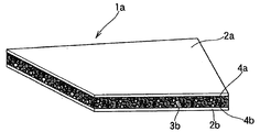
- 2 and 3 show a composite molded body (composite molding) in a state in which, after the laminated plate of FIG. 1 is molded, the foamable resin of the core material is foamed by heating to form the core material foamed resin (foamed resin).
- Panel that is, a partial cross-sectional perspective view showing an embodiment of a heat ray shielding cover.
- the laminated plate 1 of the present invention which is the material of the heat ray shielding cover (composite molded body) shown in FIGS. 2 and 3, is sandwiched between two aluminum alloy plates 2a and 2b from above.
- the adhesive resin film 4a, the foamable resin (unfoamed resin) film 3a, and the adhesive resin film 4b are sandwiched in this order.
- the adhesive resin 4 is not essential. However, it is preferable to use the adhesive resin 4 in order to ensure the bonding strength required at the time of molding the laminated plate 1 and the necessary bonding strength as a composite molded body.
- FIG. 2 shows a composite molded body 1a which is a flat heat ray shielding cover
- FIG. 3 shows a composite molded body 1b which is a HAT type heat ray shielding cover
- FIG. 2 shows a state of the composite plate 1a in which the laminated plate 1 of FIG. 1 is heated as a flat plate to foam the foamable resin 3a to obtain the foamed resin 3b as the core material
- FIG. 3 shows a state of a composite molded body (heat ray shielding cover) 1b in which the laminated plate 1 of FIG. 1 is heated after cold forming to foam the foamable resin 3a into a foamed resin 3b as a core material. .
- Laminate thickness The present invention is directed to a thin laminate for a heat ray shielding cover that is cold formed into a panel shape. Therefore, thick laminates such as buildings and structures that are not coldly formed into a panel shape are outside the scope of the present invention.
- the plate thickness is reduced for the press molding process or weight reduction.
- the thickness of the entire laminate of the present invention is preferably as thin as possible, preferably 3.4 mm or less, more preferably 2.4 mm or less.
- the thickness of the entire laminate is the total thickness of the two laminated aluminum alloy plates 2a and 2b, the adhesive resin films 4a and 4b, and the foamable resin film 3a.
- the plate thickness of the entire laminate without the adhesive resin films 4a and 4b is the total thickness of the two aluminum alloy plates 2a and 2b and the foamable resin film 3a.
- any one of the aluminum alloy plates 2a and 2b in the composite molded body is arranged with the surface facing the heat source side, that is, the heat ray (radiant heat) radiation direction from the heat source, and the heat ray from the heat source. Reflects (radiant heat).
- the aluminum alloy plates 2a and 2b block convection heat mediated by air from the heat source on both sides of the core foam resin. Thereby, even if the heat source temperature is high, the temperature of the foamed resin portion in the heat ray shielding cover is maintained at a relatively low temperature without increasing the temperature, and the heat resistance as the heat ray shielding cover (composite molded product) is guaranteed.
- all the aluminum alloys have such functions and characteristics regardless of the type of the alloy, all the aluminum alloys can be used as the aluminum alloy plates 2a and 2b.
- the heat ray shielding cover is easily exposed to a corrosive atmosphere at a high temperature, the corrosion resistance of the aluminum alloy surface is important as the heat ray shielding cover.
- the aluminum alloy surface is corroded, the effect of reflecting heat rays (radiant heat) from the heat source is reduced, and the function, durability, and heat resistance as a heat ray shielding cover are reduced.
- the aluminum alloy plates 2a and 2b selected from 1000 series, 3000 series, 5000 series, and 6000 series aluminum alloys among the aluminum alloys.
- a pure aluminum 1000 series aluminum alloy having good corrosion resistance and defined by JIS standards.
- the aluminum alloy plates 2a and 2b may be the same aluminum alloy, and the alloy type and tempering of the aluminum alloy plates 2a and 2b may be changed with each other as long as the properties such as formability and rigidity are not impaired.
- the 1000 series aluminum alloy plate is lower in strength than the 3000 series and 5000 series aluminum alloy plates, so when the plate thickness becomes extremely thin, the shape stability after cold forming is reduced. May be lower. For this reason, when using an aluminum alloy plate having a lower strength such as an O material of the 1000 series aluminum alloy plate, there is a need to make the aluminum alloy plates 2a and 2b of the laminated plate relatively thick.
- the aluminum alloy plates 2a and 2b are preferably made of a tempered material described later, which is a normal, commercially available cold-rolled plate of these aluminum alloys.
- the aluminum alloy plates 2a and 2b are basically used as a heat ray shielding cover without being painted and having no surface treatment, with a flat and smooth surface or a mirror surface.
- unevenness may be provided in an appropriate range and size over the entire surface of the aluminum alloy plates 2a and 2b or partially by embossing, pressing, or rolling.
- Each aluminum alloy plate 2a, 2b laminated on such a thin laminate plate is also preferably as thin as possible, preferably in the range of 0.05 to 1.0 mm, more preferably in the range of 0.05 to 0.5 mm. It is. However, if the thickness of the aluminum alloy plates 2a and 2b is less than 0.05 mm on one side only, the plate thickness is too thin, so the bending rigidity in the use state of the heat ray shielding cover in which the core foam resin is foamed. And the bending strength is significantly reduced.
- the thickness of the aluminum alloy plates 2a and 2b exceeds 1.0 mm on one side, strictly 0.5mm, the weight increases and the weight reduction is sacrificed, and the heat ray shielding cover is combined. The meaning itself as a molded body is lost.
- the aluminum alloy plates 2a and 2b laminated on the laminated plate are required to have appropriate strength in order to improve the cold formability (moldability and shape stability after forming) of the laminated plate.
- the aluminum alloy plates 2a and 2b are tempered materials selected from O material, H22 material to H24 material, H32 material to H34 material, and T4 material, according to the quality code defined by the JISH0001 standard. .
- This appropriate strength is also necessary for the bending rigidity and bending strength as a heat ray shielding cover.
- the strength of the aluminum alloy plate depends on the composition of the alloy, but is greatly affected by the tempering treatment. In particular, in aluminum alloy systems such as 1000 series, 3000 series, and 5000 series, the other tempered materials are too strong and cannot sufficiently improve the cold formability of the laminate to the shape of the heat ray shielding cover.
- the 3004 O material has an elongation of about 20% when the plate thickness is 1.6 mm, whereas it is 10 when the plate thickness is reduced to 0.05 mm (50 ⁇ m). It is significantly reduced to about 3% of% or less.
- the same applies to other aluminum alloy systems such as 1000 series, 5000 series, and 3000 series.
- the aluminum alloy plates 2a and 2b laminated on the material laminated plate of the heat ray shielding cover are aluminum alloy plates whose elongation is extremely reduced to 10% or less due to extremely thin plate thickness.
- the aluminum alloy plates 2a and 2b are made of the above-mentioned tempered treatment material in order to ensure the above-described required strength as a material laminate.
- the deformation amount ⁇ obtained by applying a load (molding load) to the laminated plate 1 during molding is an elastic deformation amount ⁇ E that becomes zero after the load is unloaded, and the deformation amount does not change even when the load is unloaded. It is the sum of the plastic deformation amount ⁇ P.
- the fact that it can be molded into a predetermined shape in the cold state means that immediately after unloading the molding load, the plastic deformation amount ⁇ P after the elastic deformation amount ⁇ E becomes zero becomes the target deformation amount ⁇ . It means to become.
- the above-described uniformization of the deformation amount and the uniform strain distribution by the lamination also simultaneously bring about an effect of improving the shape stability on the foamable resin side.
- a foamable resin alone has a large elastic deformation ratio (elastic deformation rate), so that even if it has a predetermined shape by plastic deformation by cold forming, it has a high buckling property to return to the original linear shape. Low shape stability.
- the aluminum alloy plate has a higher plastic deformation rate (plastic deformation rate) than the foamable resin, when the aluminum alloy plate has a predetermined shape by plastic deformation by cold forming, the original straight line The buckling ability to return to the target shape is low.
- the ratio of plastic deformation (plastic deformation rate) of the foamable resin is increased, and the shape stability is improved. For this reason, it is possible to perform cold molding such as press molding of a heat ray shielding cover having a relatively large area into a three-dimensional shape.
- the foamable resin 3a is sandwiched between the two aluminum alloy plates 2a and 2b and is molded while being constrained. For this reason, it becomes difficult to generate
- this lamination results in a structure in which the foamed core material foam resin 3b is sandwiched between the two aluminum alloy plates 2a and 2b. Thereby, even if the heat ray shielding covers 1a and 1b have a relatively large area, a lightweight composite molded body excellent in bending rigidity can be obtained.
- the board thickness (thickness of the unfoamed resin layer) of the core material foamable resin 3a of the present invention is defined below. That is, when the thickness of the laminated plate is 3.4 mm or less, the thickness of the core material foamable resin is set in the range of 0.5 to 1.4 mm. When the thickness of the laminated plate is 2.4 mm or less, the thickness of the core material foamable resin is set in the range of 0.5 to 1.4 mm. In addition, when there is "variation" in the thickness of the unfoamed resin layer depending on the part of the laminated board, the average value at the selected appropriate part of the laminated board is used.
- the core material expandable resin 3a as a laminated plate is made uniform in the strain distribution of the aluminum alloy thin plate whose elongation is extremely reduced to 10% or less during cold forming. The effect of improving the moldability is reduced. In such a case, the aluminum alloy sheet during cold forming breaks in a short period of time because it is not much different from an aluminum alloy single plate and large local elongation is likely to occur in a short time during cold forming. Is significantly reduced. If the core material foamable resin 3a is too thin, the core material foam resin 3b will be thin, and will not be lighter than a single aluminum alloy plate with the same bending rigidity or bending strength. The meaning of using the molded body as a heat ray shielding cover is lost.
- the thickness of the core foamable resin 3a is too thick, the effect of the relatively thin aluminum alloy plate (as a laminated plate) is reduced by half, which is not much different from the foamable resin alone. For this reason, even if the foamable resin having a large elastic deformation ratio (elastic deformation rate) can be made into a predetermined shape by plastic deformation by cold forming, it will return to its original linear shape. The buckling property is increased, and the shape stability is decreased. Moreover, when the plate
- Foaming ratio of core foamable resin The expansion ratio of the core material foamable resin 3a to the core material foam resin 3b (after foaming) is preferably about 2 to 20 times. As a result, it is possible to ensure that the heat ray shielding cover having a relatively large area combines light weight with bending rigidity and bending strength. If this expansion ratio is too small, the composite molded body will not be lighter than an aluminum alloy plate having the same bending rigidity or bending strength, and there is a high possibility that the use of the composite molded body for the heat ray shielding cover will disappear. . On the other hand, if the expansion ratio is too large, there is a high possibility that the bending rigidity and bending strength in the use state of the heat ray shielding cover will be significantly reduced.
- the core material foamable resin 3a of the laminate is made of a random copolymer polypropylene resin (R.PP), a homopolypropylene resin (H.PP), a melt flow rate MFR (Melting Flow Rate g /) as a polyolefin resin. 10 min) is preferably composed of one or more copolymerized polypropylene resins (B.PP) having a range of 0.1 to 50 g / 10 min. These polypropylene resins have a greater effect of improving the formability of making the strain distribution of the aluminum alloy thin plate whose elongation is lower than other resins.
- molding is possible when the core material expandable resin 3a is laminated in combination with aluminum alloy thin plates that are tempered materials such as O material, H22 material to H24 material, H32 material to H34 material, and T4 material. Greatly improves moldability such as moldability and shape stability.
- the core material foamable resin 3a of the laminated plate is obtained by further blending a commercially available heat-decomposable foaming agent into the above-described resin and kneading the resulting resin.
- a commercially available heat-decomposable foaming agent into the above-described resin and kneading the resulting resin.
- each of the above polypropylene resins may be used alone or may be blended as a polymer blend obtained by mixing these resins.
- the characteristics of the composite molded body can be made to have higher functions and more functions by blending a plurality of resins having different characteristics or containing an inorganic or metal filler or additive.
- a foamable resin, an adhesive resin, a highly vibration-damping resin, or a highly sound-absorbing resin is used, vibration damping performance, sound insulation performance, and sound absorption performance are enhanced.
- a conductive substance is used, welding performance will increase.
- a metal powder is added as a conductive substance to the foamable resin 3a or the adhesive resin 4, the resin has a high density, the sound insulation performance is improved, and the weldability can be improved.
- the melting point of the polyolefin resin used as the foamable resin 3a is 140 to 160 ° C., and the thermal decomposition temperature is about 400 ° C.
- the thermally decomposable foaming agent In order to add the thermally decomposable foaming agent to the resin and uniformly disperse it, it is necessary to knead the foaming agent at a temperature 20 to 30 ° C. higher than the melting point.
- the foaming temperature is set to 170 ° C. to 300 ° C., which is 10 ° C. or more higher than the kneading temperature and sufficiently lower than the thermal decomposition temperature. preferable. In this way, by heating the foamable resin 3a at 170 ° C. to 300 ° C., the foamable resin 3a can be uniformly foamed without deteriorating.
- the adhesive resins 4a and 4b are made of a resin capable of bonding the foamable resin 3a and the aluminum alloy plates 2a and 2b (having adhesive strength).
- a heat-seal type thermoplastic resin mainly composed of polyolefin modified with maleic anhydride or the like is used as the adhesive resin 4a. 4b is preferably used.
- foamable resins and adhesive resins are not limited to films and sheets. Either foamed resin or adhesive resin (in this case, the other may be a film or sheet), or both, are melted or dissolved in a solvent and applied with a roll or spray. May be. In this application, it is preferable that there is a step of drying after the application.
- the contact friction with the mold during press molding is reduced, the resin is prevented from being broken, and the moldability can be improved.
- the same effect can be obtained by attaching a film dedicated to lubrication on the surface of the foamable resin 3a or performing a coating for lubrication.
- Foamable resin First, the resin material constituting the expandable resin 3a is kneaded.
- This material contains a resin and a pyrolytic foaming agent, and a substance imparting adhesive strength, vibration damping properties, and heat resistance, and metal powder for improving conductivity are added as necessary. These materials are sufficiently kneaded and then formed into a film or a sheet. The material is wound into a coil when it is made into a film.
- the kneading temperature of the material is preferably set to be 10 ° C. or lower than the thermal decomposition temperature of the foaming agent used. If it does so, even if the temperature of resin rises by kneading
- Adhesive resin First, the resin material constituting the adhesive resin 4 is kneaded.
- This material is a resin to which a material for imparting adhesive strength / damping property or a metal powder for imparting conductivity is added as necessary. These materials are sufficiently kneaded and then formed into a film or a sheet. In the case of film formation, the material is wound in a coil shape and laminated separately, or is applied to the surface of an aluminum alloy plate.
- the foamable resin film or sheet and the adhesive resin may be wound into a coil after being thermally fused and integrated.
- the foamable resin sheet or film is extruded from the mold, the foamable resin and the adhesive resin are integrated so that the surface of the foamable resin is covered with the adhesive resin by two-type three-layer extrusion molding. Also good.
- the adhesive resin film 4 and the foamable resin film 3a are made of an aluminum alloy by stretching from the two coils. It can be laminated on the plate 2 at the same time.
- the foamable resin 3a since the foamable resin 3a is in an unfoamed state and has a small thickness, it can be formed into a coil shape. Therefore, since it can convey in a coil shape and can be extended from a coil at a construction place, a construction place is not restrict
- Laminate production The simplest method is to laminate the aluminum alloy plates 2a and 2b, which are cut plates, the adhesive resin film 4 which is also the cut plate, and the foamable resin film 3a in this order to form a laminated plate.
- it may be laminated continuously to form a laminated sheet. That is, both the aluminum alloy plates 2a, 2b are unwound from the coil, while the expandable resin film and the adhesive resin film are unwound from the coil and stretched while the expandable resin film and the adhesive resin film are removed. You may laminate
- the aluminum alloy plate 2 and the foamable resin 3a in FIG. 1 are bonded together via an adhesive resin, and the material laminate 1 can be manufactured.
- the temperature of this hot roll is lower than the foaming temperature of the foamable resin 3a, and is generally set near the melting point of the foamable resin and the adhesive resin.
- the manufactured laminated board 1 is cold-molded so as to have a shape of a predetermined composite molded body (panel) 1a, 1b.
- forming method press forming such as bulging forming, drawing forming, bending forming or bending can be used.
- Heating By heating the composite molded body having a predetermined shape by this molding process to the foaming temperature, the foamable resin 3a is foamed into the foamed resin 3b, and the composite molded bodies 1a and 1b are obtained. Heating can be performed after cold forming using a convection heat transfer type heating furnace such as a batch or continuous gas furnace or electric furnace. Since the aluminum alloy has a high heat ray reflectivity, a far-infrared heating furnace cannot be used as it is, but a heat ray absorbing layer such as a coating or an organic film is formed on at least one outer surface of the aluminum alloy plates 2a and 2b. It is possible to heat even a far-infrared heating furnace.
- a convection heat transfer type heating furnace such as a batch or continuous gas furnace or electric furnace. Since the aluminum alloy has a high heat ray reflectivity, a far-infrared heating furnace cannot be used as it is, but a heat ray absorbing layer such as a coating or an organic film is formed on at least one
- the foamable resin 3a is heated and foamed without transfer to form a foamed resin 3b, and further foaming that is softened by heating.
- the resin 3b can be cooled and hardened.
- a composite molded body that is foamed from a flat composite plate and has high rigidity can be produced in a short time.
- the composite molded body is soft immediately after heating and foaming, and cooling time is required to maintain the shape after molding.
- the shape is not destroyed by cooling in the same mold as molding that does not require transfer. Thus, productivity can be improved.
- the foaming resin 3a of the laminated plate 1 is first foamed and then molded, the above-described lamination effect of the aluminum alloy plates 2a and 2b and the foamable resin film 3a is halved. That is, the effect of homogenizing the strain distribution of the aluminum alloy thin plate whose elongation is extremely reduced to 10% or less of the foamed resin 3b after foaming is significantly lower than that of the unfoamed core material foamable resin 3a. The cold formability of the laminate 1 is significantly reduced.
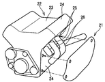
- FIG. 4 is an exploded perspective view of a heat insulator (thermal protection device) 21 of the automobile engine 22, and FIG. 5 is a partially enlarged view of the heat insulator 21 of FIG.
- an automobile engine 22 includes a cylinder head 23 and a cylinder block 24 that are joined to each other with a cylinder head gasket (not shown) interposed therebetween.
- An exhaust port hole 25 through which combustion exhaust gas is discharged is formed in the cylinder head 23 of the engine 22 of the automobile.
- a plurality of exhaust pipes (exhaust manifolds) 26 are joined to the exhaust port holes 25 via exhaust manifold gaskets (not shown).
- a cylinder head cover 24 made of synthetic resin or the like is attached to the cylinder head 23 via a rubber seal or the like.
- the exhaust pipe 26 is the only high-temperature heat source that needs to be shielded by heat rays, and the high temperature is 600 to 800 ° C.
- the other cylinder head 23, cylinder block 24, or cylinder head cover 24 is a low-temperature heat source, has a low temperature of 80 to 100 ° C., and does not require heat ray shielding. Therefore, the heat insulator 21 as a heat ray shielding cover has a HAT type shape 1b as shown in FIG. 3 as shown in FIG. 5 so as to cover the exhaust pipe 26 as a high-temperature heat source.
- the heat insulator 21 is joined to a low-temperature location (low-temperature heat source) such as the cylinder head 23, the cylinder block 24, or the cylinder head cover 24 in the vicinity of the exhaust pipe 26 that is a heat source.
- a low-temperature heat source such as the cylinder head 23, the cylinder block 24, or the cylinder head cover 24 in the vicinity of the exhaust pipe 26 that is a heat source.
- the heat insulator 21 is joined to a cylinder head cover 24 that is a low-temperature heat source. That is, a plurality of through-holes 32 are provided in the circumferentially extending flange portion 31 of the HAT-type top portion 30 of the heat insulator 21 at appropriate intervals in the circumferential direction.
- the flange portion 31 and the cylinder head cover 24 are joined to each other through the through holes 32 by mechanical joining means 40 such as bolts and nuts. In this way, by joining the heat insulator 21 to a low-temperature location near the heat source, the area of the heat
- FIG. 21 A partially enlarged view of the HAT top 30 of the heat insulator 21 is shown in the right circle in FIG.
- the side of the aluminum alloy plate 2a constituting the heat insulator 21 is arranged with the surface facing the exhaust pipe 26 side which is a heat source.
- the aluminum alloy plate 2a is arranged in the direction of radiation of the heat ray (radiant heat) from the exhaust pipe 26, which is a heat source, and reflects the heat ray (radiant heat) from the exhaust pipe 26.
- the aluminum alloy plate 2b is coated with both sides of the core material foamed resin 3b together with the aluminum alloy plate 2a to block the core material foamed resin 3b from convection heat mediated by air from the exhaust pipe 26.
- the enlarged view of the peripheral part in the flange part 31 of the heat insulator 21 is shown in the upper right circle in FIG.
- the composite molded body surface 33 at the peripheral edge of the flange portion 31 does not face the exhaust pipe 26 that is the subject of heat ray shielding.
- the heat insulator 21 is directed toward the exhaust pipe 26 so as not to expose the composite molded body surface 33 (core material foamed resin 3b) at the peripheral edge to the heat rays from the exhaust pipe 26 in terms of ensuring heat resistance. It is molded so that there is no.
- a flat plate-shaped heat ray shielding cover (composite plate 1a in which the core material foamable resin 3a is used as the core material foam resin 3b) shown in FIG. 2 was manufactured.
- the surface of the aluminum alloy plate 2a is placed upright with a 25 mm interval in the horizontal direction toward the heat source heater to form a heat ray shielding cover.
- the temperature of the core material foamed resin 3b was measured. The time course of this temperature is shown in FIG.
- the flat heat ray shielding cover does not expose the peripheral surface of the composite molded body surface (core foam resin 3b) to the heat rays from the simulated heat source heater.
- the size and distance were designed and arranged (molded so as not to face the simulated heat source heater).
- FIG. 6 also shows the result of measuring the temperature of the core foam resin 3b by placing a single unit of the core foam resin 3b upright under the same conditions as the heat ray shielding cover.
- FIG. 6 also shows the surface temperature of the simulated heat source heater, the ambient air temperature of the composite plate 1a of the heat ray shielding cover, and the like.
- the laminate 1 was manufactured as a square planar shape having a length (L direction): 600 mm and a width (LT direction): 1100 mm.
- the total thickness of the laminated plate 1 is 1.1 mm.
- a JIS3004 aluminum alloy single plate O material having a thickness of 0.05 mm (50 ⁇ m) was used.
- the total thickness of the aluminum alloy plates 2a and 2b is 0.1 mm.
- the core foamable resin 3a is common to each example, and a random copolymer polypropylene resin having a melting point of 140 ° C.
- a foaming agent having a thermal decomposition temperature of 170 to 180 ° C. is kneaded into a sheet.
- a sheet with an average plate thickness of 0.9 mm produced by extrusion was used. 4).
- the adhesive resins 4a and 4b a polyolefin-based hot-melt adhesive resin film having a melting point of 140 ° C. and a thickness of 0.05 mm was used in common with each example. The total thickness of the adhesive resin film is 0.1 mm. 5).
- Foaming condition of core foamable resin 3a Laminate 1 was heated at 175 ° C. for 6 minutes and allowed to cool. 6).
- the comparative example of the core foam resin 3b alone was manufactured under the same conditions except that the aluminum alloy plates 2a and 2b were removed from the laminated plate 1 or composite plate 1a.
- FIG. 6 shows an example of the lowest temperature (the thinnest line at the bottom, indicated by the present invention and an arrow), even if the surface temperature of the simulated heat source is as high as 600 ° C. It can be seen that the temperature of the foamed resin 3b in 1a is kept constant at around 120 ° C. That is, although the temperature of the foamed resin 3b in the composite plate 1a of the heat ray shielding cover of the present invention rises to about 120 ° C, it does not rise further over time and is kept constant at around 120 ° C. You can see that Moreover, it turns out that the ambient air temperature of the composite board 1a is also substantially the same as the temperature of the foamed resin 3b part, and shows the same progress.
- the foamed resin light weight composite plate of the present invention the aluminum wire laminated on both sides of the core material foamable resin with the reflection effect of heat rays (radiant heat) from the heat source of the aluminum alloy plate arranged toward the heat source side This confirms the convective heat insulation effect of the alloy plate. Therefore, it turns out that the foamed resin lightweight composite board of this invention can be used as the heat ray shielding cover 1a.
- the heat ray can be obtained by laminating and combining it with a foamable resin that is extremely low in cold formability. It is also supported that the cold formability (moldability and shape stability) to the shielding cover is remarkably improved. Therefore, it can be seen that the laminated plate 1 can be cold-formed into a heat ray shielding cover such as a heat insulator having a relatively large area. Also from this point, it turns out that the composite molded object 1a of this invention can be used as a heat ray shielding cover.
- the foamed resin light weight composite plate can be applied to a heat ray shielding cover such as a heat insulator, so that the heat ray shielding cover of the aluminum alloy plate or the aluminum-plated steel plate can be used. It is supported that the weight can be reduced.
- the present invention can be applied to a lightweight heat ray shielding cover having a three-dimensional shape and excellent heat ray shielding properties, such as a heat insulator.
- the present invention provides a composite molding in which a laminated board in which aluminum alloy plates are laminated on both sides of a core foamable resin is molded into a heat ray shielding cover shape, and then the core foamable resin is heated and foamed. It can also be applied as a heat ray shielding method in which a heat ray shielding cover made of a body is disposed and any aluminum alloy plate surface in the heat ray shielding cover is arranged in the vicinity of the heat source toward the heat source side.
- 1 Laminated plate
- 1a Composite molded body (or composite plate)
- 1b Composite molded body (or composite plate)
- 2 Aluminum alloy plate
- 3a (Core material) Expandable resin (film)
- 3b (Core Materials: Foamed resin
- 4 Adhesive resin (film)
- 21 Heat insulator
- 26 Exhaust pipe as heat source
- 30 Heat insulator top
- 31 Heat insulator flange
- 32 Through hole
- 33 Heat insulator periphery Part
Landscapes
- Engineering & Computer Science (AREA)
- Chemical & Material Sciences (AREA)
- Combustion & Propulsion (AREA)
- Mechanical Engineering (AREA)
- General Engineering & Computer Science (AREA)
- Physics & Mathematics (AREA)
- Acoustics & Sound (AREA)
- Laminated Bodies (AREA)
Abstract
Description
図1に示すように、図2、図3の熱線遮蔽カバー(複合成形体)の素材である本発明の積層板1は、2枚のアルミニウム合金板2a、2bの間に、図の上から順に、接着用樹脂フィルム4a、発泡性樹脂(未発泡の樹脂)フィルム3a、接着用樹脂フィルム4bが、積層した形で、挟み込まれている。
図2は平板状の熱線遮蔽カバーである複合成形体1aを示し、図3はHAT型形状の熱線遮蔽カバーである複合成形体1bを示す。図2は、図1の積層板1を平板のまま加熱して、発泡性樹脂3aを発泡させて芯材の発泡樹脂3bとした複合板1aの状態を示している。図3は、図1の積層板1を冷間成形後に加熱して、発泡性樹脂3aを発泡させて芯材の発泡樹脂3bとした複合成形体(熱線遮蔽カバー)1bの状態を示している。
本発明は、冷間でパネル形状に成形される、熱線遮蔽カバーのための薄い積層板を対象とする。したがって、冷間でパネル形状に成形されない、建築物や構造物のような厚い積層板は本発明の対象外である。前記した通り、熱線遮蔽カバーのさらなる軽量化のために、金属板単板の代わりに本発明積層板を用いて複合成形体を得る場合には、プレス成形工程や軽量化のために、板厚が金属板単板よりもあまりに厚くなった素材積層板を用いることはできない。即ち、熱線遮蔽カバーの製作側は、金属板単板の成形時と同じ成形プレス、あるいは同じプレス成形条件を用いたい。また、金属板単板の代替としては、熱線遮蔽カバーをより軽量化させることが望まれる。
熱線遮蔽カバーとして、複合成形体におけるアルミニウム合金板2a、2bのいずれかは、表面を前記熱源側に向けて、即ち、熱源からの熱線(輻射熱)放射方向に向けて配置され、熱源からの熱線(輻射熱)を反射する。また、アルミニウム合金板2a、2bは、熱源からの空気を媒介とする対流熱を、芯材発泡樹脂の両面で遮断する。これによって、熱源温度が高温であっても、熱線遮蔽カバーにおける発泡樹脂部分の温度を上昇させずに比較的低い温度に保持し、熱線遮蔽カバー(複合成形体)としての耐熱性を保証する。
このような薄い積層板に積層されるアルミニウム合金板2a、2bの各板厚も、薄いほど好ましく、好ましくは0.05~1.0mmの範囲、より好ましくは0.05~0.5mmの範囲である。ただ、アルミニウム合金板2a、2bの板厚が、片側一方だけでも0.05mm未満の場合には、板厚が薄すぎるため、芯材発泡樹脂が発泡した熱線遮蔽カバーの使用状態での曲げ剛性および曲げ強度が著しく低下する。一方、アルミニウム合金板2a、2bの板厚が、片側一方だけでも1.0mm、厳しくは0.5mmを超える場合には、重量が重くなり、軽量化が犠牲となって、熱線遮蔽カバーを複合成形体とする意味自体が失われる。
積層板に積層されるアルミニウム合金板2a、2bは、積層板の冷間成形性(成形可能性、成形後の形状安定性)の向上のために、適正な強度が必要である。このため、アルミニウム合金板2a、2bは、JISH0001規格にて規定される質別記号で、O材、H22材~H24材、H32材~H34材及びT4材から選択される調質処理材とする。この適正な強度は、熱線遮蔽カバーとしての曲げ剛性や曲げ強度にも必要である。アルミニウム合金板の強度は、勿論、合金の成組成にもよるが、調質処理による影響が大きい。特に、1000系、3000系、5000系などのアルミニウム合金系では、これ以外の調質処理材は、強度が高すぎ、積層板の熱線遮蔽カバー形状への冷間成形性を十分に向上できない。
このように、2枚のアルミニウム合金板2a、2bの間に、未発泡の発泡性樹脂3aと接着用樹脂4bとを積層した(挟み込む)場合、前記した通り、アルミニウム合金板単体、発泡性樹脂単体の場合に比して、冷間成形性向上効果と冷間成形後の形状安定性の向上効果がもたらされる。アルミニウム合金板と発泡性樹脂との積層化によって、アルミニウム合金板が薄板であっても、その歪み分布が均一化する。このため、冷間成形において、大きな局所的な伸びが生じないか、あるいは大きな局所的な伸びが生じるまでの時間が遅くなるので、冷間成形中のアルミニウム合金薄板が短時間には破断しなくなる。
以上のような積層板の構成を前提にして、以下に、本発明の芯材発泡性樹脂3aの板厚(未発泡樹脂層の厚み)を規定する。即ち、積層板の板厚が3.4mm以下である場合には、芯材発泡性樹脂の板厚を0.5~1.4mmの範囲とする。また、積層板の板厚が2.4mm以下である場合には、芯材発泡性樹脂の板厚を0.5~1.4mmの範囲とする。なお、積層板の部位により、未発泡樹脂層の厚みに「ばらつき」がある場合には、積層板の選択された適当部位における平均値とする。
芯材発泡性樹脂3aの、芯材発泡樹脂3b(発泡後)への発泡倍率は、2~20倍程度とすることが好ましい。これによって、比較的大きな面積を有する熱線遮蔽カバーの、軽量化と曲げ剛性および曲げ強度の兼備を保証できる。この発泡倍率が小さすぎると、曲げ剛性か曲げ強度が同じアルミニウム合金板単体に比して、複合成形体が軽量とはならず、熱線遮蔽カバーに複合成形体を使う意味がなくなる可能性が高い。一方、この発泡倍率が大きすぎると、熱線遮蔽カバーの使用状態での曲げ剛性および曲げ強度が著しく低下する可能性が高い。
積層板の芯材発泡性樹脂3aは、ポリオレフィン系樹脂として、ランダム共重合ポリプロピレン系樹脂(R.PP)、ホモポリプロピレン系樹脂(H.PP)、溶融時の流れ性MFR(Melting Flow Rate g/10min )が0.1~50g/10minの範囲である共重合ポリプロピレン系樹脂(B.PP)の一種または二種以上からなることが好ましい。これらのポリプロピレン系樹脂は、他の樹脂に比して、伸びが低下したアルミニウム合金薄板の歪み分布を均一化する前記成形性向上効果が大きい。即ち、芯材発泡性樹脂3aが、O材、H22材~H24材、H32材~H34材及びT4材などの調質処理材であるアルミニウム合金薄板と組み合わされて積層された場合に、成形可能性や形状安定性などの成形性向上効果が大きい。
樹脂応用例として、特性の異なる複数の樹脂をブレンドしたり、無機系や金属系のフィラーや添加剤を含有させることにより、複合成形体の特性をより高機能、多機能とすることができる。例えば、発泡性樹脂、接着用樹脂、制振性の高い樹脂、吸音性の高い樹脂を用いれば、制振性能や遮音性能、吸音性能が高まる。また、導電性物質を用いれば、溶接性能が高まる。上記の発泡性樹脂3aや接着用樹脂4に導電性物質として金属粉末が添加されると、樹脂は高密度となり、遮音性能が高まるとともに、溶接性が向上できる。
接着用樹脂4a、4bは、発泡性樹脂3aとアルミニウム合金板2a、2bとの接着が可能な(接着強度を有する)樹脂からなる。芯材発泡性樹脂の主成分として、前記したポリオレフィン系樹脂を用いた場合には、無水マレイン酸などで変性させたポリオレフィンを主成分とする熱融着タイプの熱可塑性樹脂が、接着用樹脂4a、4bとして好適に用いられる。
これら発泡性樹脂、接着用樹脂は、フィルム・シートであるものに限らない。発泡性樹脂、接着用樹脂のうち、何れか一方(この場合、他方はフィルム・シートでよい)、または両方を、溶融状態または溶媒に溶解させた状態のものを、ロールやスプレーなどで塗布してもよい。なお、この塗布の場合には、塗布後に乾燥する工程があることが好ましい。
ここで、熱線遮蔽カバー(複合成形体)の製造方法について、以下に説明する。
はじめに、発泡性樹脂3aを構成する樹脂材料が混練される。この材料は、樹脂と熱分解型発泡剤とを含んでおり、必要に応じて、接着強度、制振性、耐熱性を付与する物質や、導電性向上のための金属粉末が添加される。これらの材料は、十分混練された後、フィルム化あるいはシート化される。上記材料は、フィルム化される場合にはコイル状に巻かれる。このとき、上記材料の混練温度は、用いられる発泡剤の熱分解温度よりも10℃以上低く設定されていることが好ましい。そうすると、混練されることで樹脂の温度が上昇しても、発泡の発生を防止することができる。
はじめに、接着用樹脂4を構成する樹脂材料が混練される。この材料は、必要に応じて、接着強度・制振性付与する材質や、導電性を付与するための金属粉末が添加された樹脂である。これらの材料は、十分混練された後、フィルム化あるいはシート化される。上記材料は、フィルム化の場合には、コイル状に巻かれて別途積層されるか、アルミニウム合金板の表面に塗布される。
切り板とされたアルミニウム合金板2a、2bと、同じく切り板とされた接着用樹脂フィルム4と、発泡性樹脂フィルム3aとを、順に積層して、積層板となす方法が最も簡便である。ただ、設備的に可能であれば、連続的に積層して積層板をなしてもよい。即ち、アルミニウム合金板2a、2bの両方をコイルから巻き出し、一方で、上記発泡性樹脂フィルムおよび接着用樹脂フィルムを各々コイルから巻き出して引き伸ばしながら、上記発泡性樹脂フィルムおよび接着用樹脂フィルムをアルミニウム合金板2a、2bの間に同時に積層してもよい。これらの積層後、例えば熱ロールなどにより挟み込んで加熱すれば、図1におけるアルミニウム合金板2と発泡性樹脂3aとが接着用樹脂を介して一体に接着され、素材積層板1が製作できる。この熱ロールの温度は、発泡性樹脂3aの発泡温度よりも低く、概ね発泡性樹脂および接着用樹脂の融点近傍に設定される。これにより、元来接着性のないポリオレフィンからなる発泡性樹脂と、アルミニウム合金板表面に出来た水酸化皮膜とを変性ポリオレフィンにより接着することができる。この結果として、冷間成形に必要なアルミニウム合金板と発泡性樹脂との界面の接着強度を確保することが出来る。
製造された積層板1は、所定の複合成形体(パネル)1a、1bの形状となるように、冷間成形される。成形加工の方法としては、張出成形、絞り成形、曲げ成形などのプレス成形や曲げ加工が使用可能である。
この成形加工によって所定形状とされた複合成形体を発泡温度まで加熱することにより、発泡性樹脂3aが発泡して発泡樹脂3bとなり、複合成形体1a、1bが得られる。加熱は、バッチ式または連続式のガス炉、電気炉などの対流伝熱方式の加熱炉を用いて、冷間成形後に行うことが出来る。アルミニウム合金は熱線反射率が高いために、そのままでは遠赤外線式の加熱炉を用いることが出来ないが、アルミニウム合金板2a、2bのうち少なくとも片側の外側表面に塗装や有機皮膜などの熱線吸収層を設けることにより、遠赤外線式加熱炉でも加熱することができる。また、加熱および/または冷却が可能な熱間プレスを用いれば、冷間でプレス成形した後、トランスファーなしで発泡性樹脂3aを加熱発泡して発泡樹脂3bとし、さらに加熱により柔らかくなっている発泡樹脂3bを冷却して硬くすることができる。これにより、平坦な複合板から発泡して高剛性になった複合成形体を短時間に生産することが出来る。さらに、加熱発泡直後は複合成形体が柔らかく、成形後の形状を維持するには冷却時間が必要であったが、トランスファーの必要がない成形と同一の金型内での冷却により形状を崩さないように短時間で取り出すことが出来るので、生産性を高めることができる。
次に、これら製造した熱線遮蔽カバーの使用態様である熱線遮蔽方法としての態様を、図4、5を用いて、以下に説明する。図4は自動車エンジン22のヒートインシュレータ(熱防護装置)21の分解斜視図であり、図5は、この図4のヒートインシュレータ21の部分拡大図である。
1.積層板1は、長さ(L方向):600mm、幅(LT方向):1100mmの四角の平面形状として製作した。積層板1の合計板厚は1.1mmである。
2.積層板1を構成するアルミニウム合金板2a、2bには、板厚0.05mm(50μm)の、JIS3004アルミニウム合金単板のO材を用いた。アルミニウム合金板2a、2bの板厚合計は0.1mmである。
3.芯材発泡性樹脂3aは、各例とも共通して、融点140℃のランダム共重合ポリプロピレン系樹脂をベース樹脂とし、これに熱分解温度が170~180℃の発泡剤を混錬してシートに押し出すことにより製作した、平均板厚:0.9mmのシートを用いた。
4.接着用樹脂4a、4bは、各例とも共通して、融点:140℃、厚み:0.05mmのポリオレフィン系のホットメルト接着樹脂フィルムを用いた。接着樹脂フィルムの板厚合計は0.1mmである。
5.芯材発泡性樹脂3aの発泡条件:積層板1を175℃×6分間加熱し、放冷した。
6.前記芯材発泡樹脂3b単体の比較例は、上記積層板1または複合板1aからアルミニウム合金板2a、2bを除く以外は、同じ条件により製作した。
Claims (6)
- 熱源近傍に配置されて熱源からの熱線を遮蔽するカバーであって、
芯材発泡性樹脂の両面にアルミニウム合金板が各々積層された積層板をカバー形状に成形した後に、前記芯材発泡性樹脂を加熱して発泡させた複合成形体からなり、
この複合成形体におけるいずれかのアルミニウム合金板表面が、前記熱源側に向けて配置されることを特徴とする熱線遮蔽カバー。 - 前記熱線遮蔽カバー周縁部の複合成形体面を、熱線遮蔽の対象とする前記熱源方向には向けないように、前記複合成形体が成形されている請求項1に記載の熱線遮蔽カバー。
- 熱線遮蔽の対象とする前記熱源近傍の低温箇所に接合される請求項1または2に記載の熱線遮蔽カバー。
- 前記積層板の板厚が3.4mm以下であり、
前記アルミニウム合金板の板厚が0.05~1.0mmであるとともに、前記芯材発泡性樹脂の板厚が0.5~1.4mmであり、
前記アルミニウム合金板が、JISH0001規格にて規定される質別記号で、O材、H22材~H24材、H32材~H34材及びT4材のうちから選択される調質処理材である請求項1に記載の熱線遮蔽カバー。 - 前記積層板の板厚が2.4mm以下であり、
前記アルミニウム合金板の板厚が0.05~0.5mmであるとともに、前記芯材発泡性樹脂の板厚が0.5~1.4mmである請求項4に記載の熱線遮蔽カバー。 - 前記アルミニウム合金板が、1000系、3000系、5000系、6000系のアルミニウム合金から選択される請求項4に記載の熱線遮蔽カバー。
Priority Applications (2)
| Application Number | Priority Date | Filing Date | Title |
|---|---|---|---|
| US12/737,975 US20110159247A1 (en) | 2008-09-09 | 2009-09-09 | Heat ray shield cover |
| CN2009801343735A CN102144081A (zh) | 2008-09-09 | 2009-09-09 | 热射线屏蔽罩 |
Applications Claiming Priority (2)
| Application Number | Priority Date | Filing Date | Title |
|---|---|---|---|
| JP2008-231245 | 2008-09-09 | ||
| JP2008231245A JP2010065564A (ja) | 2008-09-09 | 2008-09-09 | 熱線遮蔽カバー |
Publications (1)
| Publication Number | Publication Date |
|---|---|
| WO2010029946A1 true WO2010029946A1 (ja) | 2010-03-18 |
Family
ID=42005199
Family Applications (1)
| Application Number | Title | Priority Date | Filing Date |
|---|---|---|---|
| PCT/JP2009/065759 Ceased WO2010029946A1 (ja) | 2008-09-09 | 2009-09-09 | 熱線遮蔽カバー |
Country Status (4)
| Country | Link |
|---|---|
| US (1) | US20110159247A1 (ja) |
| JP (1) | JP2010065564A (ja) |
| CN (1) | CN102144081A (ja) |
| WO (1) | WO2010029946A1 (ja) |
Cited By (4)
| Publication number | Priority date | Publication date | Assignee | Title |
|---|---|---|---|---|
| US20120315463A1 (en) * | 2011-06-10 | 2012-12-13 | Kabushiki Kaisha Kobe Seiko Sho (Kobe Steel, Ltd.) | Laminated sheet and composite formed article using the same |
| US9790836B2 (en) | 2012-11-20 | 2017-10-17 | Tenneco Automotive Operating Company, Inc. | Loose-fill insulation exhaust gas treatment device and methods of manufacturing |
| JP2017221957A (ja) * | 2016-06-14 | 2017-12-21 | 三菱アルミニウム株式会社 | アルミニウム樹脂複合積層板の曲げ加工方法 |
| WO2025120957A1 (ja) * | 2023-12-07 | 2025-06-12 | 株式会社神戸製鋼所 | 複合構造体及びその製造方法 |
Families Citing this family (9)
| Publication number | Priority date | Publication date | Assignee | Title |
|---|---|---|---|---|
| JP2011140067A (ja) * | 2009-12-10 | 2011-07-21 | Kobe Steel Ltd | 鋼板とアルミニウム板との接合構造体の製造方法およびこの製造方法により製造された鋼板とアルミニウム板との接合構造体 |
| DE102013102859B4 (de) * | 2013-03-20 | 2015-04-02 | Tenneco Gmbh | Flanschplatte für einen Krümmer einer Abgasanlage |
| GB201309323D0 (en) * | 2013-05-23 | 2013-07-10 | 4A Mfg Gmbh | Three-dimensional structural member formed by a sandwich structure with foam core between metallic layers |
| JP6636298B2 (ja) * | 2015-10-07 | 2020-01-29 | 日野自動車株式会社 | ヒートインシュレータ |
| US9840989B2 (en) * | 2015-11-30 | 2017-12-12 | Ford Global Technologies, Llc | Soft engine cover for intake manifold |
| GB2549955A (en) | 2016-05-03 | 2017-11-08 | 4A Mfg Gmbh | Membrane plate structure for generating sound waves |
| USD826498S1 (en) * | 2017-09-17 | 2018-08-21 | Michael Ross Catania | Combined sponge and steel wool pad |
| JP7206945B2 (ja) * | 2019-01-23 | 2023-01-18 | スズキ株式会社 | 車両用内燃機関 |
| JP7359179B2 (ja) * | 2021-03-15 | 2023-10-11 | Jfeスチール株式会社 | 自動車用部品 |
Citations (3)
| Publication number | Priority date | Publication date | Assignee | Title |
|---|---|---|---|---|
| JPH10196398A (ja) * | 1997-01-17 | 1998-07-28 | Sanshin Ind Co Ltd | 推進機用エンジン |
| JP2006250054A (ja) * | 2005-03-11 | 2006-09-21 | Toyota Motor Corp | 内燃機関の遮音構造 |
| JP7090621B2 (ja) * | 2016-12-30 | 2022-06-24 | コーニンクレッカ フィリップス エヌ ヴェ | 静電蠕動ポンプ及び動作方法 |
Family Cites Families (15)
| Publication number | Priority date | Publication date | Assignee | Title |
|---|---|---|---|---|
| JPS56151531A (en) * | 1980-04-25 | 1981-11-24 | Nissan Motor Co Ltd | Manufacture of low noise engine cover or the like |
| JPH0790621B2 (ja) * | 1987-04-03 | 1995-10-04 | 三菱化学株式会社 | 発泡プラスチツク複合板 |
| US4996095A (en) * | 1987-07-01 | 1991-02-26 | Vereinigte Aluminum Werke A.G. | Composite material of aluminum and glass fiber mat, method for its production, and method for utilization as insulator for vehicles |
| DE3721715A1 (de) * | 1987-07-01 | 1989-01-12 | Vaw Ver Aluminium Werke Ag | Verbundwerkstoff aus aluminium und glasfasermatten und verfahren zu seiner herstellung |
| JPH0453299Y2 (ja) * | 1987-07-31 | 1992-12-15 | ||
| US5030488A (en) * | 1988-11-23 | 1991-07-09 | Chemical And Polymer Technology, Inc. | Laminates, panels and means for joining them |
| JPH0790621A (ja) * | 1993-08-09 | 1995-04-04 | Kawasaki Steel Corp | スポット抵抗溶接性および加工性に優れた表面処理アルミニウム板 |
| CN2193272Y (zh) * | 1994-05-09 | 1995-03-29 | 江锡铭 | 车辆防护罩 |
| US5656675A (en) * | 1994-11-09 | 1997-08-12 | Mitsui Petrochemical Industries, Ltd. | Automotive molded roof material and process for producing the same |
| US5603297A (en) * | 1996-01-18 | 1997-02-18 | Acoust-A-Fiber Research And Development, Inc. | Heat Shield |
| US6569510B1 (en) * | 2000-05-02 | 2003-05-27 | Hari Menon | Retro-flective sheeting on metal coil composites |
| US7585557B2 (en) * | 2004-02-17 | 2009-09-08 | Eastman Kodak Company | Foam core imaging element with gradient density core |
| US8186325B2 (en) * | 2006-01-05 | 2012-05-29 | Federal-Mogul World Wide, Inc. | Heat shield having locating and retention features |
| JP4783184B2 (ja) * | 2006-03-20 | 2011-09-28 | 株式会社神戸製鋼所 | 発泡性樹脂積層金属板 |
| CN201050153Y (zh) * | 2007-09-27 | 2008-04-23 | 杨军 | 保温隔音铝塑复合装饰板 |
-
2008
- 2008-09-09 JP JP2008231245A patent/JP2010065564A/ja active Pending
-
2009
- 2009-09-09 WO PCT/JP2009/065759 patent/WO2010029946A1/ja not_active Ceased
- 2009-09-09 US US12/737,975 patent/US20110159247A1/en not_active Abandoned
- 2009-09-09 CN CN2009801343735A patent/CN102144081A/zh active Pending
Patent Citations (3)
| Publication number | Priority date | Publication date | Assignee | Title |
|---|---|---|---|---|
| JPH10196398A (ja) * | 1997-01-17 | 1998-07-28 | Sanshin Ind Co Ltd | 推進機用エンジン |
| JP2006250054A (ja) * | 2005-03-11 | 2006-09-21 | Toyota Motor Corp | 内燃機関の遮音構造 |
| JP7090621B2 (ja) * | 2016-12-30 | 2022-06-24 | コーニンクレッカ フィリップス エヌ ヴェ | 静電蠕動ポンプ及び動作方法 |
Cited By (5)
| Publication number | Priority date | Publication date | Assignee | Title |
|---|---|---|---|---|
| US20120315463A1 (en) * | 2011-06-10 | 2012-12-13 | Kabushiki Kaisha Kobe Seiko Sho (Kobe Steel, Ltd.) | Laminated sheet and composite formed article using the same |
| US9079385B2 (en) * | 2011-06-10 | 2015-07-14 | Kobe Steel, Ltd. | Laminated sheet and composite formed article using the same |
| US9790836B2 (en) | 2012-11-20 | 2017-10-17 | Tenneco Automotive Operating Company, Inc. | Loose-fill insulation exhaust gas treatment device and methods of manufacturing |
| JP2017221957A (ja) * | 2016-06-14 | 2017-12-21 | 三菱アルミニウム株式会社 | アルミニウム樹脂複合積層板の曲げ加工方法 |
| WO2025120957A1 (ja) * | 2023-12-07 | 2025-06-12 | 株式会社神戸製鋼所 | 複合構造体及びその製造方法 |
Also Published As
| Publication number | Publication date |
|---|---|
| CN102144081A (zh) | 2011-08-03 |
| JP2010065564A (ja) | 2010-03-25 |
| US20110159247A1 (en) | 2011-06-30 |
Similar Documents
| Publication | Publication Date | Title |
|---|---|---|
| WO2010029946A1 (ja) | 熱線遮蔽カバー | |
| JP4559513B2 (ja) | 積層板および複合成形体 | |
| US9962909B2 (en) | Composite materials including regions differing properties, and methods | |
| Ning et al. | Design and development of thermoplastic composite roof door for mass transit bus | |
| JP2009090522A (ja) | 複合板および複合成形体 | |
| EP2669888A1 (en) | Sound-proof material and process for production thereof, sound-proof molding, and sound insulation method | |
| JP2007022183A (ja) | 車両用防音材 | |
| JP5410424B2 (ja) | 改善された音響性能を有する複合ヘッドライナ | |
| JP4381941B2 (ja) | 自動車内装天井材用の積層部材 | |
| JP2017171179A (ja) | 車両用防音材及びその製造方法 | |
| JP4384573B2 (ja) | 自動車内装天井材用の積層部材 | |
| JP5952948B1 (ja) | アルミニウム樹脂複合積層板 | |
| JP2011152843A (ja) | 車両用内装材およびその成形方法 | |
| JP2017221957A (ja) | アルミニウム樹脂複合積層板の曲げ加工方法 | |
| JP2010036675A (ja) | 車両用軽量多層構造防音材 | |
| JP2017192972A (ja) | アルミニウム樹脂複合積層板の絞り成形用ブランク材及びこれを用いた三次元成形品の製造方法 | |
| JP6313579B2 (ja) | 外板用樹脂積層板 | |
| JP2018012108A (ja) | アルミニウム樹脂複合積層板のプレス成形方法 | |
| JP2015034372A (ja) | 複合パネル | |
| JP6752412B2 (ja) | アルミニウム樹脂複合積層板 | |
| JP2019507047A (ja) | 車両用成形トリム部品 | |
| KR101926865B1 (ko) | 전도성 및 차열성을 가지는 멀티레이어 강판의 제조 방법 및 이에 의해 제조되는 멀티레이어 강판 | |
| WO2009104646A1 (ja) | 複合板および複合成形体、複合成形体の製造方法 | |
| JP2022140925A (ja) | 自動車用部品 | |
| US8129003B2 (en) | Vehicle panel with metalized film |
Legal Events
| Date | Code | Title | Description |
|---|---|---|---|
| WWE | Wipo information: entry into national phase |
Ref document number: 200980134373.5 Country of ref document: CN |
|
| 121 | Ep: the epo has been informed by wipo that ep was designated in this application |
Ref document number: 09813092 Country of ref document: EP Kind code of ref document: A1 |
|
| WWE | Wipo information: entry into national phase |
Ref document number: 1574/CHENP/2011 Country of ref document: IN |
|
| NENP | Non-entry into the national phase |
Ref country code: DE |
|
| 122 | Ep: pct application non-entry in european phase |
Ref document number: 09813092 Country of ref document: EP Kind code of ref document: A1 |