WO2010001500A1 - ボンディング装置 - Google Patents
ボンディング装置 Download PDFInfo
- Publication number
- WO2010001500A1 WO2010001500A1 PCT/JP2008/072969 JP2008072969W WO2010001500A1 WO 2010001500 A1 WO2010001500 A1 WO 2010001500A1 JP 2008072969 W JP2008072969 W JP 2008072969W WO 2010001500 A1 WO2010001500 A1 WO 2010001500A1
- Authority
- WO
- WIPO (PCT)
- Prior art keywords
- bonding
- vibration
- amplitude
- ultrasonic
- output
- Prior art date
- Legal status (The legal status is an assumption and is not a legal conclusion. Google has not performed a legal analysis and makes no representation as to the accuracy of the status listed.)
- Ceased
Links
Images





Classifications
-
- B—PERFORMING OPERATIONS; TRANSPORTING
- B23—MACHINE TOOLS; METAL-WORKING NOT OTHERWISE PROVIDED FOR
- B23K—SOLDERING OR UNSOLDERING; WELDING; CLADDING OR PLATING BY SOLDERING OR WELDING; CUTTING BY APPLYING HEAT LOCALLY, e.g. FLAME CUTTING; WORKING BY LASER BEAM
- B23K20/00—Non-electric welding by applying impact or other pressure, with or without the application of heat, e.g. cladding or plating
- B23K20/002—Non-electric welding by applying impact or other pressure, with or without the application of heat, e.g. cladding or plating specially adapted for particular articles or work
- B23K20/004—Wire welding
- B23K20/005—Capillary welding
- B23K20/007—Ball bonding
-
- B—PERFORMING OPERATIONS; TRANSPORTING
- B23—MACHINE TOOLS; METAL-WORKING NOT OTHERWISE PROVIDED FOR
- B23K—SOLDERING OR UNSOLDERING; WELDING; CLADDING OR PLATING BY SOLDERING OR WELDING; CUTTING BY APPLYING HEAT LOCALLY, e.g. FLAME CUTTING; WORKING BY LASER BEAM
- B23K2101/00—Articles made by soldering, welding or cutting
- B23K2101/36—Electric or electronic devices
- B23K2101/42—Printed circuits
-
- H—ELECTRICITY
- H10—SEMICONDUCTOR DEVICES; ELECTRIC SOLID-STATE DEVICES NOT OTHERWISE PROVIDED FOR
- H10W—GENERIC PACKAGES, INTERCONNECTIONS, CONNECTORS OR OTHER CONSTRUCTIONAL DETAILS OF DEVICES COVERED BY CLASS H10
- H10W72/00—Interconnections or connectors in packages
- H10W72/071—Connecting or disconnecting
- H10W72/0711—Apparatus therefor
- H10W72/07141—Means for applying energy, e.g. ovens or lasers
-
- H—ELECTRICITY
- H10—SEMICONDUCTOR DEVICES; ELECTRIC SOLID-STATE DEVICES NOT OTHERWISE PROVIDED FOR
- H10W—GENERIC PACKAGES, INTERCONNECTIONS, CONNECTORS OR OTHER CONSTRUCTIONAL DETAILS OF DEVICES COVERED BY CLASS H10
- H10W72/00—Interconnections or connectors in packages
- H10W72/071—Connecting or disconnecting
- H10W72/0711—Apparatus therefor
- H10W72/07183—Means for monitoring
-
- H—ELECTRICITY
- H10—SEMICONDUCTOR DEVICES; ELECTRIC SOLID-STATE DEVICES NOT OTHERWISE PROVIDED FOR
- H10W—GENERIC PACKAGES, INTERCONNECTIONS, CONNECTORS OR OTHER CONSTRUCTIONAL DETAILS OF DEVICES COVERED BY CLASS H10
- H10W72/00—Interconnections or connectors in packages
- H10W72/071—Connecting or disconnecting
- H10W72/075—Connecting or disconnecting of bond wires
- H10W72/07531—Techniques
- H10W72/07532—Compression bonding, e.g. thermocompression bonding
- H10W72/07533—Ultrasonic bonding, e.g. thermosonic bonding
-
- H—ELECTRICITY
- H10—SEMICONDUCTOR DEVICES; ELECTRIC SOLID-STATE DEVICES NOT OTHERWISE PROVIDED FOR
- H10W—GENERIC PACKAGES, INTERCONNECTIONS, CONNECTORS OR OTHER CONSTRUCTIONAL DETAILS OF DEVICES COVERED BY CLASS H10
- H10W72/00—Interconnections or connectors in packages
- H10W72/50—Bond wires
- H10W72/551—Materials of bond wires
- H10W72/552—Materials of bond wires comprising metals or metalloids, e.g. silver
Definitions
- the present invention relates to a structure of a bonding apparatus.
- the wire bonding apparatus In a manufacturing process of a semiconductor device, a wire bonding apparatus that connects a pad that is an electrode of a semiconductor chip and a lead that is an electrode of a lead frame with a wire that is a thin metal wire is often used.
- the wire bonding apparatus includes a bonding arm rotated by a drive motor, an ultrasonic horn attached to the bonding arm, a capillary attached to the tip of the ultrasonic horn, and an ultrasonic transducer attached to the ultrasonic horn.
- bonding is performed by resonating the ultrasonic horn and applying ultrasonic vibration to the tip of the capillary.
- the control unit of the wire bonding apparatus controls the current value applied to the drive motor and the current value applied to the ultrasonic transducer so as to apply a predetermined bonding load and ultrasonic output set in advance during the bonding operation. is doing.
- Patent Document 1 proposes that a strain gauge is attached to an ultrasonic horn, a bonding load and ultrasonic vibration are detected by the strain gauge, and a voltage applied to the drive motor and the ultrasonic vibrator is controlled. Has been.
- Patent Document 2 a load detection sensor using a piezoelectric material and an ultrasonic vibration detection sensor are provided on the same surface between the capillary and the ultrasonic transducer, and the bonding load is calculated from each output. It has been proposed to detect the output of ultrasonic vibrations.
- An object of the present invention is to detect a vibration load applied to the tip of a bonding tool with a simple configuration in a bonding apparatus.
- the bonding apparatus of the present invention includes a base unit, an ultrasonic horn that resonates with the vibration of the ultrasonic vibrator and longitudinally vibrates in the longitudinal direction, a bonding tool attached to the antinode of the vibration of the ultrasonic horn, and an ultrasonic horn Includes a flange provided at the vibration node and a flange mounting surface to which the flange of the ultrasonic horn is fixed, and is rotatably attached to the base so that the tip of the bonding tool can be moved toward and away from the bonding target From the signal acquired by the load sensor by the bonding arm, a load sensor attached between the rotation center of the bonding arm and the flange mounting surface, and a filter that passes signals in the frequency band near the vibration frequency of the ultrasonic transducer. Extract the signal in the frequency band near the vibration frequency of the sonic transducer, and based on the extracted signal And having a vibration load detection unit for detecting the ultrasonic horn longitudinal vibration load applied to down loading tool tip, the
- the vibration load detection unit is configured to detect a gap between an initial ball formed at the tip of the bonding tool and a bonding target based on a change in amplitude of the vibration load in the longitudinal direction of the ultrasonic horn applied to the detected tip of the bonding tool. It is also preferable to include a bonding state determination unit that determines a bonding state of the bonding member and outputs a bonding state signal.
- the bonding state determination unit of the vibration load detection unit is an ultrasonic wave applied to the tip of the bonding tool after the start of bonding.
- the amplitude increasing period in which the amplitude of the vibration load in the longitudinal direction of the horn increases and the amplitude stabilizing period in which the amplitude becomes substantially constant after the amplitude increasing period are the initial balls formed at the tip of the bonding tool being crushed and bonded to the object to be bonded It is determined that the welding is in progress, and a joining state signal is output to Outputting a junction termination signal junction termination judged to when a predetermined time has elapsed since the amplitude is increased than also suitable as.
- the vibration load detection unit is connected and includes a control unit that changes the output of the ultrasonic vibrator.
- the control unit receives ultrasonic waves when a joining end signal is input from the vibration load detection unit. It is also preferable to provide ultrasonic vibration stopping means for stopping the output of the vibrator, and when the amplitude of the amplitude stabilization period detected by the vibration load detecting unit is smaller than a predetermined value, the control unit The output of the ultrasonic transducer is increased from a preset output, and when the amplitude in the amplitude stabilization period is larger than a predetermined value, the output of the ultrasonic transducer is decreased from the preset output. It is also preferable to provide ultrasonic vibration changing means.
- the present invention has an effect that the vibration load applied to the tip of the bonding tool can be detected with a simple configuration in the bonding apparatus.
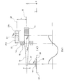
- a wire bonding apparatus 10 of this embodiment includes a bonding head 11 that is a base portion, an ultrasonic vibrator 13, an ultrasonic horn 12, a capillary 17 that is a bonding tool, and an ultrasonic horn. 12, the flange 14, the bonding arm 21, the load sensor 31, the drive motor 45, the vibration load detection unit 50, the control unit 60, and the semiconductor chip 34 and the substrate 35 to be bonded are fixed by suction. A bonding stage 33.
- the bonding head 11 is provided with a drive motor 45 that rotationally drives the bonding arm 21.
- the ultrasonic transducer 13 is a superposition of a plurality of piezoelectric elements, and is attached to the rear end side of the ultrasonic horn 12.
- a capillary 17 is attached to the tip of the ultrasonic horn 12.
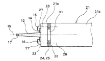
- a flange 14 is provided at a position to be a vibration node of the ultrasonic horn 12 to be described later, and the flange 14 is fixed to a flange mounting surface 22 at the tip of the bonding arm 21 by a bolt 16.
- the bonding arm 21 is rotatably attached around a rotation shaft 30 provided on the bonding head 11.
- the rotation center 43 of the bonding arm 21 is on the same plane as the surface of the substrate 35 adsorbed on the bonding stage 33 or the surface of the semiconductor chip 34 attached to the substrate 35.
- the bonding arm 21 is a substantially rectangular parallelepiped extending in the direction of the central axis 15 of the ultrasonic horn 12, and has a front end side portion 21 a having a flange mounting surface 22 and a rear end side portion 21 b including a rotation center 43.
- the portion 21 a and the rear end side portion 21 b are connected by a thin plate-like connection portion 24 provided at a height direction position (Z direction position) including the central axis 15 of the ultrasonic horn 12.
- thin slits 23 and 25 are provided between the front end side portion 21a and the rear end side portion 21b of the bonding arm 21.
- a groove 26 for attaching the load sensor 31 is provided on the upper side in the Z direction opposite to the bonding surface 41 of the bonding arm 21.
- the groove 26 is provided between the front end side portion 21a and the rear end side portion 21b of the bonding arm 21 so as to face each other.
- the load sensor 31 attached to the groove 26 is sandwiched between the front end portion 21a and the rear end portion 21b by a screw 27 screwed from the bonding arm front end portion 21a toward the rear end portion 21b. It is configured to be pressurized.
- the load sensor 31 is attached such that the center axis 28 is offset from the center axis 15 of the ultrasonic horn 12 by a distance L in the Z direction, which is the contact / separation direction between the bonding surface 41 and the tip 17a of the capillary 17.
- the load sensor 31 is attached to the center portion in the width direction of the bonding arm 21, and the screws 27 are provided on both sides of the load sensor 31. Further, as shown in FIG. 2B, a recess 29 in which the ultrasonic horn 12 and the ultrasonic transducer 13 are accommodated is provided on the bonding surface 41 side of the bonding arm 21.
- the ultrasonic horn 12 resonates in the longitudinal direction, which is the direction along the central axis 15, and vibrates longitudinally by the ultrasonic vibrator 13.
- longitudinal vibration refers to vibration in which the direction of vibration and the direction of amplitude are the same.
- the ultrasonic horn 12 includes a rear end to which the ultrasonic transducer 13 is attached and a tip to which the capillary 17 is attached by vibration of the ultrasonic transducer 13 attached to the rear end. , The rear end and the front end vibrate in a resonance mode that becomes an antinode of vibration.
- a flange 14 for fixing the ultrasonic horn 12 to the bonding arm 21 is provided at a vibration node formed between the rear end and the front end, that is, a portion that does not vibrate even in a resonance state.
- the flange 14 is fixed to the flange mounting surface 22 of the bonding arm 21 with bolts 16. Since the flange 14 does not vibrate due to the resonance of the ultrasonic horn 12, the ultrasonic wave due to the resonance of the ultrasonic horn 12 is not transmitted to the flange mounting surface 22 of the bonding arm 21. For this reason, the ultrasonic vibration due to the resonance of the ultrasonic horn 12 is not transmitted to the load sensor 31 provided in the bonding arm 21.
- FIG. 3 is a schematic diagram for explaining the relationship between the bonding arm 21, the ultrasonic horn 12, the flange 14, and the bolt 16.
- the flange 14 extending from the ultrasonic horn 12 in the horizontal and XY directions is vertically arranged. It is written in the direction.
- FIG. 3B schematically shows the amplitude of the ultrasonic horn 12, and the amplitude in the direction of the central axis 15 is described as the amplitude in the direction perpendicular to the central axis 15.
- the load sensor 31 is connected to the vibration load detection unit 50, and includes a bandpass filter that passes a signal in a frequency band in the vicinity of the vibration frequency of the ultrasonic transducer inside the load sensor 31.
- the vibration load along the direction of the central axis 15 of the ultrasonic horn 12 applied to the tip 17a of the capillary 17 can be detected from the signal detected by 31.
- the ultrasonic vibrator 13, the drive motor 45, and the vibration load detection unit 50 are connected to the control unit 60, and the output of the ultrasonic vibrator 13, the rotation direction and the output of the drive motor 45 are controlled by commands from the control unit 60.
- the vibration load detected by the vibration load detection unit 50 is input to the control unit 60.
- the vibration load detection unit 50 and the control unit 60 may be configured as a computer including a CPU, a memory, and the like, or may be a detection and control system configured by an electric circuit.
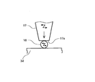
- the control unit 60 shown in FIG. 1 forms the tip of the wire extending from the tip 17a of the capillary 17 into a spherical initial ball 18 by a discharge torch or the like (not shown). Then, the control unit 60 outputs a command for driving the drive motor 45. By this command, the drive motor 45 starts to rotate and starts to lower the capillary 17 toward the semiconductor chip 34. Further, the control unit 60 outputs a command for starting the vibration of the ultrasonic transducer 13. By this command, a voltage capable of outputting a vibration output set in advance corresponding to the bonding condition is applied to the ultrasonic transducer 13.
- the ultrasonic horn 12 Before the initial ball 18 formed at the tip of the capillary 17 contacts the surface of the semiconductor chip 34, the ultrasonic horn 12 resonates with the vibration of the ultrasonic vibrator 13 as shown in FIG. A longitudinal vibration is generated with the front end and the rear end to which the ultrasonic transducer 13 is attached as the antinode of vibration. Since the flange 14 is arranged at the vibration node, it does not vibrate due to the resonance of the ultrasonic horn 12, and the load sensor 31 does not detect the load.
- the capillary 17 starts to press the initial ball 18 toward the pad. Then, a bending moment is applied to the ultrasonic horn 12 by the Z-direction pressing force applied to the capillary 17. This bending moment is transmitted from the flange 14 to the tip end portion 21 a of the bonding arm 21. Then, the tip end portion 21a of the bonding arm 21 tries to rotate in the clockwise direction using the thin plate-like connection portion 24 as a rotary hinge. The load sensor 31 is compressed by this rotational moment, and the load sensor 31 starts to detect the ground load of the capillary 17.
- the flange mounting surface 22 of the bonding arm 21 similarly vibrates along the direction of the central axis 15 of the ultrasonic horn 12, and the vibration load is detected by the load sensor 31.
- the frequency of resonance along the direction of the central axis 15 of the ultrasonic horn 12 and the frequency along the direction of the central axis 15 of the ultrasonic horn 12 generated at the tip 17a of the capillary 17 are substantially the same. It has become.
- the vibration load applied to the tip 17a of the capillary 17 in the direction of the central axis 15 of the ultrasonic horn 12 is compared to the ground load in the Z direction perpendicular to the central axis 15 of the ultrasonic horn 12 at the tip of the capillary 17. Since the load is very small, most of the load detected by the load sensor 31 is a ground load signal as shown in FIG. On the other hand, the vibration load applied to the tip 17a of the capillary 17 in the direction of the central axis 15 of the ultrasonic horn 12 is a frequency having substantially the same frequency as the vibration frequency of the ultrasonic horn 12, and as shown in FIG.
- a vibration load signal applied from the tip 17a of the capillary 17 in the direction of the central axis 15 of the ultrasonic horn 12 can be extracted from the output of the load sensor 31.
- the magnitude of the vibration load can be detected from the amplitude of the extracted signal.
- the ultrasonic vibration stop for detecting the change in the bonding state between the initial ball 18 and the pad of the semiconductor chip 34 and adjusting the output of the ultrasonic vibrator 13 during the bonding by the vibration load detected as described above. Means and ultrasonic vibration changing means will be described.
- the vibration load detector 50 acquires a signal from the load sensor 31. Then, as shown in step S102 of FIG. 6, the detected signal is passed through the narrowband filter 51 to extract only a signal in the vicinity of the vibration frequency band of the ultrasonic horn 12, and vibration is generated as shown in step S103 of FIG. Detect load.
- the vibration load detection unit 50 acquires the detected vibration load from the vibration load detection unit 50, and determines whether the amplitude of the vibration load increases from zero or an amplitude stabilization period. As to whether or not it is the amplitude increase period, an increase rate with respect to time of the amplitude may be calculated, and if the increase rate exceeds a threshold value, it may be determined that it is the amplitude increase period. Whether or not it is the amplitude stabilization period may be determined as a case where the rate of change of the amplitude with respect to time exceeds a threshold value and that the amplitude is within the upper and lower threshold values.
- the vibration load detection unit 50 determines whether the change in the amplitude of the vibration load along the direction of the central axis 15 of the ultrasonic horn 12 of the capillary 17 during bonding is in the amplitude increase period. If it is determined that the amplitude is stable, a joining signal indicating that the bonding state is in the middle of joining is output as shown in step S105 of FIG. When the vibration load detector 50 determines that the change in the amplitude of the vibration load along the direction of the central axis 15 of the ultrasonic horn 12 of the capillary 17 is neither an amplitude increase period nor an amplitude stabilization period, FIG.
- step S109 it is determined whether or not a predetermined time has elapsed. Before the predetermined time elapses, a joining halfway signal is output as shown in step S105 of FIG.
- the vibration load detection unit 50 determines that the change in the amplitude of the vibration load along the direction of the central axis 15 of the ultrasonic horn 12 of the capillary 17 is neither an amplitude increase period nor an amplitude stabilization period, and is predetermined. If it is determined that the time has elapsed, a joining end signal is output as shown in step S110 of FIG.
- the control unit 60 connected to the vibration load detection unit 50, as shown in step S106 of FIG.
- the amplitude of the vibration load corresponding to the output of the ultrasonic transducer 13 set in advance is compared, and the amplitude of the detected vibration load is compared with the amplitude of the vibration load corresponding to the output of the ultrasonic transducer 13 set in advance. If it is smaller, it is determined that the output of the ultrasonic transducer 13 at the time of joining is insufficient, and the output of the ultrasonic transducer 13 is increased as shown in step S107 of FIG.
- the output of the ultrasonic transducer 13 at the time of joining is excessive. As shown in step S108 in FIG. 6, the output of the ultrasonic transducer 13 is reduced (ultrasonic vibration changing means).
- the control unit 60 determines that the crimping of the initial ball 18 is finished and the ultrasonic vibration by the ultrasonic vibrator 13 is no longer necessary. As shown in step S111 in FIG. 6, the supply of voltage to the ultrasonic transducer 13 is stopped to stop the ultrasonic transducer 13 (ultrasonic vibration stopping means).
- the wire bonding apparatus 10 of the present embodiment can detect the vibration load applied to the tip 17a of the capillary 17 during bonding with a simple configuration, so that the capillary 17 in the middle of bonding can be detected. There is an effect that the behavior can be constantly confirmed.
- the present embodiment can determine the bonding state between the initial ball 18 and the bonding target in the middle of bonding, the output of the ultrasonic vibrator 13 is increased / decreased according to the bonding state, and the bonding condition is appropriately set. It is possible to improve the bonding quality by controlling to the above.
- a band-pass filter having a narrow band centered on the frequency of ultrasonic vibration is used as a filter for extracting only a signal in the vicinity of the vibration frequency band of the ultrasonic horn 12 from the signal of the load sensor 31.
- a configuration may be adopted in which only a signal in the vicinity of the vibration frequency band of the ultrasonic horn 12 is extracted by combining a low-pass filter and a high-pass filter having a cutoff frequency near the ultrasonic vibration frequency.
- the wire bonding apparatus has been described.
- the present invention is not limited to the wire bonding apparatus but can be applied to other bonding apparatuses such as a bump bonding apparatus.
Landscapes
- Engineering & Computer Science (AREA)
- Mechanical Engineering (AREA)
- Wire Bonding (AREA)
- Pressure Welding/Diffusion-Bonding (AREA)
Priority Applications (2)
| Application Number | Priority Date | Filing Date | Title |
|---|---|---|---|
| CN200880130099XA CN102077334B (zh) | 2008-06-30 | 2008-12-17 | 焊接装置 |
| US12/982,019 US8800843B2 (en) | 2008-06-30 | 2010-12-30 | Bonding apparatus |
Applications Claiming Priority (2)
| Application Number | Priority Date | Filing Date | Title |
|---|---|---|---|
| JP2008169797A JP4314313B1 (ja) | 2008-06-30 | 2008-06-30 | ボンディング装置 |
| JP2008-169797 | 2008-06-30 |
Related Child Applications (1)
| Application Number | Title | Priority Date | Filing Date |
|---|---|---|---|
| US12/982,019 Continuation US8800843B2 (en) | 2008-06-30 | 2010-12-30 | Bonding apparatus |
Publications (1)
| Publication Number | Publication Date |
|---|---|
| WO2010001500A1 true WO2010001500A1 (ja) | 2010-01-07 |
Family
ID=41036723
Family Applications (1)
| Application Number | Title | Priority Date | Filing Date |
|---|---|---|---|
| PCT/JP2008/072969 Ceased WO2010001500A1 (ja) | 2008-06-30 | 2008-12-17 | ボンディング装置 |
Country Status (5)
| Country | Link |
|---|---|
| US (1) | US8800843B2 (https=) |
| JP (1) | JP4314313B1 (https=) |
| CN (1) | CN102077334B (https=) |
| TW (1) | TW201000238A (https=) |
| WO (1) | WO2010001500A1 (https=) |
Families Citing this family (24)
| Publication number | Priority date | Publication date | Assignee | Title |
|---|---|---|---|---|
| KR101417252B1 (ko) * | 2012-02-24 | 2014-07-08 | 엘지이노텍 주식회사 | 카메라 모듈의 기판 접합 장치 |
| JP5960292B2 (ja) * | 2013-01-15 | 2016-08-02 | 日産自動車株式会社 | 接合状態検査方法 |
| JP5930419B2 (ja) * | 2014-03-14 | 2016-06-08 | 株式会社カイジョー | ボンディング装置 |
| JP5930423B2 (ja) * | 2014-05-09 | 2016-06-08 | 株式会社カイジョー | ボンディング装置 |
| WO2017109990A1 (ja) * | 2015-12-25 | 2017-06-29 | 株式会社カイジョー | ワイヤボンディング装置 |
| JP6316340B2 (ja) * | 2016-06-02 | 2018-04-25 | 株式会社カイジョー | ボンディング装置、ボンディング方法及びボンディング制御プログラム |
| KR102206867B1 (ko) * | 2016-09-07 | 2021-01-25 | 가부시키가이샤 신가와 | 와이어 본딩 장치 |
| JP7008370B2 (ja) * | 2018-07-11 | 2022-02-14 | 株式会社新川 | ワイヤボンディング装置 |
| CN112585732B (zh) * | 2018-08-06 | 2024-10-11 | 株式会社新川 | 接合头 |
| CN109702315B (zh) * | 2018-12-27 | 2024-05-03 | 东莞市鸿振超声波设备有限公司 | 一种利用位置与压力触发的超声波控制电路及焊接方法 |
| US11901329B2 (en) * | 2019-06-17 | 2024-02-13 | Kaijo Corporation | Wire bonding method and wire bonding apparatus |
| JP7577501B2 (ja) * | 2020-10-07 | 2024-11-05 | 株式会社東芝 | 超音波接合装置、制御装置及び制御方法 |
| KR102622020B1 (ko) * | 2021-02-22 | 2024-01-08 | 가부시키가이샤 신가와 | 와이어 본딩 장치 |
| JP7209416B1 (ja) * | 2021-06-14 | 2023-01-20 | 株式会社新川 | 超音波ホーンおよび半導体装置の製造装置 |
| JP7343941B2 (ja) * | 2021-06-17 | 2023-09-13 | 株式会社新川 | 超音波複合振動装置および半導体装置の製造装置 |
| US11691214B2 (en) * | 2021-10-17 | 2023-07-04 | Shinkawa Ltd. | Ultrasound horn |
| US11798911B1 (en) * | 2022-04-25 | 2023-10-24 | Asmpt Singapore Pte. Ltd. | Force sensor in an ultrasonic wire bonding device |
| JP2024011603A (ja) * | 2022-07-15 | 2024-01-25 | 株式会社新川 | 半導体装置の製造装置および製造方法 |
| NL2033279B1 (en) | 2022-10-11 | 2024-04-26 | Canon Kk | Bonding tool for connecting a printhead unit to an FPC |
| US20240116126A1 (en) * | 2022-10-11 | 2024-04-11 | Asmpt Singapore Pte. Ltd. | Ultrasonic transducer operable at multiple resonant frequencies |
| US20240116127A1 (en) * | 2022-10-11 | 2024-04-11 | Asmpt Singapore Pte. Ltd. | Ultrasonic transducer operable at multiple resonant frequencies |
| JP7510203B2 (ja) * | 2022-11-08 | 2024-07-03 | 株式会社新川 | クランプ装置並びにその制御方法及び制御プログラム |
| JP7592331B2 (ja) * | 2023-03-22 | 2024-12-02 | 株式会社新川 | ワイヤボンディング装置及び該装置の較正方法 |
| WO2025105065A1 (ja) * | 2023-11-15 | 2025-05-22 | 株式会社新川 | キャピラリを交換する方法及びワイヤボンディング装置 |
Citations (4)
| Publication number | Priority date | Publication date | Assignee | Title |
|---|---|---|---|---|
| JPH05206224A (ja) * | 1992-01-24 | 1993-08-13 | Hitachi Ltd | 超音波接合装置及び品質モニタリング方法 |
| JPH10256320A (ja) * | 1997-03-12 | 1998-09-25 | Toshiba Mechatronics Kk | 半導体製造装置 |
| JP2003258021A (ja) * | 2002-03-04 | 2003-09-12 | Kaijo Corp | ワイヤボンディング装置 |
| JP2008021839A (ja) * | 2006-07-13 | 2008-01-31 | Shinkawa Ltd | ワイヤボンディング装置 |
Family Cites Families (4)
| Publication number | Priority date | Publication date | Assignee | Title |
|---|---|---|---|---|
| WO2004073914A1 (en) * | 1999-11-10 | 2004-09-02 | Asm Technology Singapore Pte Ltd. | Force sensing apparatus |
| US6279810B1 (en) * | 2000-02-23 | 2001-08-28 | Asm Assembly Automation Ltd | Piezoelectric sensor for measuring bonding parameters |
| CN100556602C (zh) * | 2007-12-24 | 2009-11-04 | 哈尔滨工业大学 | 超声波辅助激光钎焊或激光钎熔焊的方法 |
| JP5206224B2 (ja) | 2008-08-21 | 2013-06-12 | 横浜ゴム株式会社 | 空気入りタイヤ |
-
2008
- 2008-06-30 JP JP2008169797A patent/JP4314313B1/ja active Active
- 2008-11-19 TW TW97144641A patent/TW201000238A/zh not_active IP Right Cessation
- 2008-12-17 CN CN200880130099XA patent/CN102077334B/zh active Active
- 2008-12-17 WO PCT/JP2008/072969 patent/WO2010001500A1/ja not_active Ceased
-
2010
- 2010-12-30 US US12/982,019 patent/US8800843B2/en active Active
Patent Citations (4)
| Publication number | Priority date | Publication date | Assignee | Title |
|---|---|---|---|---|
| JPH05206224A (ja) * | 1992-01-24 | 1993-08-13 | Hitachi Ltd | 超音波接合装置及び品質モニタリング方法 |
| JPH10256320A (ja) * | 1997-03-12 | 1998-09-25 | Toshiba Mechatronics Kk | 半導体製造装置 |
| JP2003258021A (ja) * | 2002-03-04 | 2003-09-12 | Kaijo Corp | ワイヤボンディング装置 |
| JP2008021839A (ja) * | 2006-07-13 | 2008-01-31 | Shinkawa Ltd | ワイヤボンディング装置 |
Also Published As
| Publication number | Publication date |
|---|---|
| US8800843B2 (en) | 2014-08-12 |
| US20110155789A1 (en) | 2011-06-30 |
| TW201000238A (en) | 2010-01-01 |
| CN102077334B (zh) | 2013-05-01 |
| TWI361122B (https=) | 2012-04-01 |
| JP4314313B1 (ja) | 2009-08-12 |
| JP2010010510A (ja) | 2010-01-14 |
| CN102077334A (zh) | 2011-05-25 |
Similar Documents
| Publication | Publication Date | Title |
|---|---|---|
| JP4314313B1 (ja) | ボンディング装置 | |
| JP4275724B1 (ja) | ボンディング良否判定方法およびボンディング良否判定装置ならびにボンディング装置 | |
| WO2018110417A1 (ja) | ワイヤボンディング装置及びワイヤボンディング方法 | |
| WO2015122410A1 (ja) | ワイヤボンディング装置及び半導体装置の製造方法 | |
| US20210272927A1 (en) | Wire bonding apparatus | |
| JP4595020B2 (ja) | ボンディング装置及びボンディングツール振巾測定方法ならびにボンディングツール振巾較正方法 | |
| JP4722117B2 (ja) | ワイヤボンディング装置 | |
| JP7191421B2 (ja) | ワイヤボンディング装置 | |
| KR20150019158A (ko) | 초음파 본딩 타입 메탈 와이어 본딩 장치 | |
| JP2017216314A (ja) | ボンディング装置、ボンディング方法及びプログラム | |
| JP3818932B2 (ja) | ワイヤボンディング装置 | |
| JP2000174056A (ja) | ワイヤボンディング装置 | |
| JP4337042B2 (ja) | 接合方法 | |
| JP4109074B2 (ja) | 超音波ホーンとそのツール保持方法及びそれを用いたバンプボンディング装置 | |
| JPH10256320A (ja) | 半導体製造装置 | |
| JP2977028B2 (ja) | 超音波ワイヤボンディング装置の振動状態監視方法及び装置 | |
| JPH08203955A (ja) | ボンディング装置 | |
| JP3442900B2 (ja) | ボンディング装置 | |
| JP2877771B2 (ja) | ワイヤボンディング装置 | |
| JP2001267352A (ja) | ワイヤボンディング装置およびその制御方法 | |
| JP2006237075A (ja) | ボンディング方法およびボンディング装置 | |
| JP2006269539A (ja) | 電子部品の製造方法および電子部品の製造装置 | |
| JPH08181161A (ja) | ボンディング装置 |
Legal Events
| Date | Code | Title | Description |
|---|---|---|---|
| WWE | Wipo information: entry into national phase |
Ref document number: 200880130099.X Country of ref document: CN |
|
| 121 | Ep: the epo has been informed by wipo that ep was designated in this application |
Ref document number: 08874875 Country of ref document: EP Kind code of ref document: A1 |
|
| NENP | Non-entry into the national phase |
Ref country code: DE |
|
| 122 | Ep: pct application non-entry in european phase |
Ref document number: 08874875 Country of ref document: EP Kind code of ref document: A1 |