WO2009145036A1 - 動力伝達装置 - Google Patents
動力伝達装置 Download PDFInfo
- Publication number
- WO2009145036A1 WO2009145036A1 PCT/JP2009/058614 JP2009058614W WO2009145036A1 WO 2009145036 A1 WO2009145036 A1 WO 2009145036A1 JP 2009058614 W JP2009058614 W JP 2009058614W WO 2009145036 A1 WO2009145036 A1 WO 2009145036A1
- Authority
- WO
- WIPO (PCT)
- Prior art keywords
- power transmission
- lead screw
- stepping motor
- screw
- axial direction
- Prior art date
Links
- 230000005540 biological transmission Effects 0.000 title claims abstract description 77
- 238000003780 insertion Methods 0.000 claims description 3
- 230000037431 insertion Effects 0.000 claims description 3
- 239000004973 liquid crystal related substance Substances 0.000 description 19
- 238000002955 isolation Methods 0.000 description 8
- 239000000463 material Substances 0.000 description 5
- 229920003002 synthetic resin Polymers 0.000 description 5
- 239000000057 synthetic resin Substances 0.000 description 5
- 230000005284 excitation Effects 0.000 description 3
- 238000005286 illumination Methods 0.000 description 3
- 239000000758 substrate Substances 0.000 description 3
- 239000011521 glass Substances 0.000 description 2
- 238000000034 method Methods 0.000 description 2
- 239000011347 resin Substances 0.000 description 2
- 229920005989 resin Polymers 0.000 description 2
- 239000004925 Acrylic resin Substances 0.000 description 1
- 229920000178 Acrylic resin Polymers 0.000 description 1
- 229930182556 Polyacetal Natural products 0.000 description 1
- 239000004743 Polypropylene Substances 0.000 description 1
- 239000002390 adhesive tape Substances 0.000 description 1
- 229910052782 aluminium Inorganic materials 0.000 description 1
- XAGFODPZIPBFFR-UHFFFAOYSA-N aluminium Chemical compound [Al] XAGFODPZIPBFFR-UHFFFAOYSA-N 0.000 description 1
- 238000005452 bending Methods 0.000 description 1
- 230000015572 biosynthetic process Effects 0.000 description 1
- 238000000151 deposition Methods 0.000 description 1
- 238000004512 die casting Methods 0.000 description 1
- 230000020169 heat generation Effects 0.000 description 1
- 229910052751 metal Inorganic materials 0.000 description 1
- 239000002184 metal Substances 0.000 description 1
- 239000007769 metal material Substances 0.000 description 1
- 239000000203 mixture Substances 0.000 description 1
- 230000003287 optical effect Effects 0.000 description 1
- 230000002093 peripheral effect Effects 0.000 description 1
- 239000004417 polycarbonate Substances 0.000 description 1
- 229920000515 polycarbonate Polymers 0.000 description 1
- 229920006324 polyoxymethylene Polymers 0.000 description 1
- -1 polypropylene Polymers 0.000 description 1
- 229920001155 polypropylene Polymers 0.000 description 1
- 238000002310 reflectometry Methods 0.000 description 1
- 230000000717 retained effect Effects 0.000 description 1
- 238000009751 slip forming Methods 0.000 description 1
- 230000001360 synchronised effect Effects 0.000 description 1
- 238000007740 vapor deposition Methods 0.000 description 1
Images
Classifications
-
- G—PHYSICS
- G02—OPTICS
- G02B—OPTICAL ELEMENTS, SYSTEMS OR APPARATUS
- G02B27/00—Optical systems or apparatus not provided for by any of the groups G02B1/00 - G02B26/00, G02B30/00
- G02B27/01—Head-up displays
- G02B27/0149—Head-up displays characterised by mechanical features
-
- B60K35/23—
-
- F—MECHANICAL ENGINEERING; LIGHTING; HEATING; WEAPONS; BLASTING
- F16—ENGINEERING ELEMENTS AND UNITS; GENERAL MEASURES FOR PRODUCING AND MAINTAINING EFFECTIVE FUNCTIONING OF MACHINES OR INSTALLATIONS; THERMAL INSULATION IN GENERAL
- F16H—GEARING
- F16H25/00—Gearings comprising primarily only cams, cam-followers and screw-and-nut mechanisms
- F16H25/18—Gearings comprising primarily only cams, cam-followers and screw-and-nut mechanisms for conveying or interconverting oscillating or reciprocating motions
- F16H25/20—Screw mechanisms
- F16H25/2015—Means specially adapted for stopping actuators in the end position; Position sensing means
-
- F—MECHANICAL ENGINEERING; LIGHTING; HEATING; WEAPONS; BLASTING
- F16—ENGINEERING ELEMENTS AND UNITS; GENERAL MEASURES FOR PRODUCING AND MAINTAINING EFFECTIVE FUNCTIONING OF MACHINES OR INSTALLATIONS; THERMAL INSULATION IN GENERAL
- F16H—GEARING
- F16H25/00—Gearings comprising primarily only cams, cam-followers and screw-and-nut mechanisms
- F16H25/18—Gearings comprising primarily only cams, cam-followers and screw-and-nut mechanisms for conveying or interconverting oscillating or reciprocating motions
- F16H25/20—Screw mechanisms
- F16H25/2021—Screw mechanisms with means for avoiding overloading
-
- Y—GENERAL TAGGING OF NEW TECHNOLOGICAL DEVELOPMENTS; GENERAL TAGGING OF CROSS-SECTIONAL TECHNOLOGIES SPANNING OVER SEVERAL SECTIONS OF THE IPC; TECHNICAL SUBJECTS COVERED BY FORMER USPC CROSS-REFERENCE ART COLLECTIONS [XRACs] AND DIGESTS
- Y10—TECHNICAL SUBJECTS COVERED BY FORMER USPC
- Y10T—TECHNICAL SUBJECTS COVERED BY FORMER US CLASSIFICATION
- Y10T74/00—Machine element or mechanism
- Y10T74/18—Mechanical movements
- Y10T74/18568—Reciprocating or oscillating to or from alternating rotary
- Y10T74/18576—Reciprocating or oscillating to or from alternating rotary including screw and nut
Definitions
- the present invention relates to a power transmission device that includes a power transmission unit that operates in response to driving of a drive member such as a stepping motor, and that transmits power to a driven transmission unit by the operation of the power transmission unit.
- the vehicle head-up display device described in Patent Document 1 includes a display that emits display light, a reflector that reflects display light emitted from the display, and a housing that houses the display and the reflector. Mainly configured, the display light reflected by the concave mirror provided in the reflector is projected (irradiated) on the windshield of the vehicle through the emitting part formed in the housing, and the display image (virtual image) obtained by this irradiation is projected on the vehicle The user (occupant) is visually recognized.
- the reflector includes a concave mirror that reflects display light from the display, a mirror holder that holds the concave mirror, and a shaft that is integrally formed with the mirror holder and that extends on the rotation axis. And a power transmission device for transmitting power.
- the control unit sets the stepping motor so that the angular position of the concave mirror becomes a predetermined angular position based on the operation signal.
- a command signal (drive signal) for driving is output.
- the gear portion rotates about the shaft portion (that is, the rotation axis of the mirror holder), and the concave mirror held by the mirror holder and the mirror holder thereby Rotating about the rotation axis, the concave mirror is arranged at a predetermined angular position.
- control unit outputs a control signal for maintaining the mirror holder position for maintaining the arrangement position of the mirror holder at the position after completion of the adjustment even after the adjustment of the angular position in the mirror holder is completed. Control to output to the stepping motor was performed.
- an object of the present invention is to provide a power transmission device in which a drive member is not damaged in order to cope with the above-described problems.
- the present invention includes a drive member that is driven based on a command signal from a control unit, a lead screw portion that is rotationally driven as the drive member is driven, and an axial direction of the lead screw portion by rotation of the lead screw portion.
- a power transmission device including a power transmission unit that moves along the power transmission unit and transmits power to the power transmission unit, wherein the control unit is configured to move to the drive member when the power transmission unit is not moving along the axial direction. The control of stopping the output of the command signal is performed.
- the present invention is characterized in that the power transmission portion is formed with an insertion portion for inserting a guide shaft that is substantially parallel to the lead screw portion.
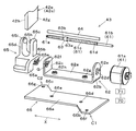
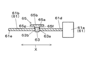
- FIG. 1 is a schematic view of a head-up display device according to an embodiment of the present invention. It is sectional drawing of the head-up display apparatus by the same embodiment. It is a perspective view which shows the 2nd reflector by the same embodiment. It is sectional drawing which shows the 2nd reflector by the same embodiment, and the required part of a housing. It is a perspective view which shows the to-be-powered transmission part and power transmission device by the embodiment. It is sectional drawing which shows the positional relationship of the drive means in the power transmission device by the same embodiment, a moving member, and a power transmission part.
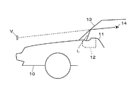
- the head-up display device uses the windshield 13 of the vehicle 10 that is a projection member to project the display light L that is projected by the display device 12 that is a display unit disposed inside the instrument panel 11 of the vehicle 10.
- the virtual image V is displayed by reflecting in the direction of the driver (user) 14.
- the head-up display device emits (projects) display light L emitted from a liquid crystal display (to be described later) of the display device 12 onto the windshield 13 (the projection member), and a display image ( Virtual image) V is made visible to the user 14. Thereby, the user 14 can observe the virtual image V superimposed on the landscape.
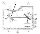
- the liquid crystal display 20 has a light source 21 formed of a light emitting diode mounted on the wiring board R and a front side (directly above) the light source 21 so as to transmit the illumination light from the light source 21 and form the display light L. It is mainly composed of a TFT-type liquid crystal display element (display element) 22 positioned. This is because the light source 21 is disposed behind (directly below) the liquid crystal display element 22, and the liquid crystal display element 22 displays predetermined information (information to be described later) by illumination light emitted from the light source 21. Means.
- the liquid crystal display 20 is provided in the housing 50 such that the surface on the emission side of the display light L faces a cold mirror (to be described later) of the first reflector 30, and the optical axis of the display light L is on the cold mirror. Fixed and held at a crossing position and orientation.
- the cold mirror 31 reflects light in the visible wavelength range (450 to 750 nm) including the emission wavelength range of the liquid crystal display 20 with a high reflectance (for example, 80% or more), and lowers light outside the visible wavelength range. It reflects with reflectivity.
- a cold mirror 31 that reflects light in the infrared wavelength region other than the visible wavelength region (infrared rays or heat rays of sunlight) with a low reflectance (for example, 15% or less) is applied.
- the light that is not reflected by the first reflective layer 31 b is configured to pass through the cold mirror 31.
- the cold mirror 31 and the liquid crystal display 20 are arranged at a position where they cannot directly face a translucent cover (to be described later) of the housing 50, and light from outside such as sunlight (external light) Is a structure that does not directly hit.
- the attachment member 32 is made of, for example, a black synthetic resin material and is fixed to the housing 50.
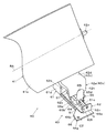
- the second reflector 40 includes a concave mirror (reflecting member) 41 that reflects the display light L from the cold mirror 31 (that is, the liquid crystal display element 22), and a mirror holder that holds the concave mirror 41. 42 and a power transmission device 43 for transmitting power to a later-described hanging portion of the mirror holder 42 in order to adjust the angular position (arrangement position) of the mirror holder 42.
- the concave mirror 41 is for reflecting (projecting) the display light L from the cold mirror 31 toward the translucent cover (the windshield 13 of the vehicle 10). This means that the concave mirror 41 enlarges the display light L reflected by the cold mirror 31 and projects the enlarged display light L onto the windshield 13 through the translucent cover.
- Reference numeral 42c denotes a protruding piece formed in a substantially L shape from the back of the concave mirror 41 toward the second reflecting layer 41a side below the concave mirror 41.
- the protruding piece 42c is formed with a tongue piece 42d.
- a hanging portion 42e and is formed integrally with the mirror holder 42. Further, the hanging portion 42e of the protruding piece 42c provided in the mirror holder 42 corresponds to the driven force transmitting portion in claim 1 of the present application.
- the tongue piece 42d extends from the bottom surface portion 42f constituting the bottom wall of the holding portion 42b of the mirror holder 42 toward the second reflective layer 41a (in other words, the lead screw portion described later). It consists of a substantially rectangular flat plate (extending along a substantially axial direction).
- the hanging portion 42e which is a driven force transmission portion, is a substantially rectangular flat plate-like standing wall portion continuously formed on the tongue piece 42d so as to hang downward (from the lead screw portion side) from the tip portion of the tongue piece 42d. Consists of.
- the drooping portion 42e is configured such that both surfaces 42g and 42h (see FIG. 4) are in point contact with a pair of first and second protrusions of a power transmission unit (described later) provided in the power transmission device 43. Sandwiched by the first and second protrusions.
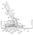
- the power transmission device 43 mainly includes a driving means 61, a support body 62, a moving member 63, a guide shaft 64, a power transmission portion 65, and a vibration isolation member 66.
- the mirror holder 42 is rotated about the rotation axis RA to adjust the angular position of the mirror holder 42 (concave mirror 41) (in other words, the projection direction of the display light L is adjusted).
- reference numeral 70 denotes a control unit composed of a microcomputer having ROM, RAM, CPU, etc., and the stepping motor 61a is driven based on a command signal (drive signal) from the control unit 70.
- the drive signal output from the control unit 70 is output to a motor drive circuit 71 connected to the control unit 70.
- the support body 62 is formed of a metal motor case that fixes and supports the stepping motor 61a in an immobile state, is formed in a substantially U-shaped cross section, and is a substantially plate that is disposed along the axial direction X of the lead screw portion 61c. And a pair of first and second flange portions 62b, 62c formed by bending both ends of the flat plate portion 62a along the axial direction X so as to correspond to the stepping motor 61a, Have
- the first flange portion 62b located on the stepping motor 61a side is fitted with a through hole 62d through which an end portion (terminal portion) 61d of the lead screw portion 61c passes and one end portion of the guide shaft 64. 1 fitting hole 62e is formed.
- the first flange portion 62b and the required portion of the stepping motor 61a are fixed to each other by a predetermined mounting means, whereby the stepping motor 61a is fixedly supported by the support body 62 in an immobile state. Become.
- a hole (not shown) corresponding to the through hole 62d and a first fitting hole 62e are provided corresponding to the guide shaft 64.
- a second fitting hole 62f into which the other end is fitted is formed.
- a bearing member G is mounted in the hole provided in the second flange portion 62c. Then, the tip 61e portion of the lead screw portion 61c located on the tip side of the projecting portion that penetrates the through hole 62d and projects to the bearing member G side is rotatably supported through the bearing member G.
- the first and second screw threaded portions 62g and 62h are formed so as to protrude in a substantially cylindrical shape on the surface side of the flat plate portion 62a on both ends of the flat plate portion 62a.
- the first screw A screwing portion 62g is provided in the vicinity of the first flange portion 62b
- a second screw screwing portion 62h is provided in the vicinity of the second flange portion 62c.
- the power transmission portion 65 is made of a synthetic resin material such as polyacetal, and a pair of first and second protrusions formed so as to face each other upward from the base portion 65a and the surface portion 65b of the base portion 65a. Counter walls 65c and 65d.
- the base portion 65a has an insertion portion 65e having a substantially circular through-hole shape through which the guide shaft 64 is inserted, and a required portion of the first and second side surfaces 63a and 63b that are both side surfaces of the moving member 63, respectively.
- a pair of first and second contact portions 65f and 65g formed in contact (surface contact) are formed (see FIG. 6).
- the first and second contact portions 65f and 65g are integrally formed with the base portion 65a so as to partially sandwich the first and second side surfaces 63a and 63b of the moving member 63.
- a surface on the first flange portion 62b side is a first side surface 63a
- a surface on the second flange portion 62c side is a second side surface 63b.
- the first contact portion 65f and the first side surface 63a are in contact with each other
- the second contact portion 65g and the second side surface 63b are in contact with each other, so that the first and second contact portions 65f and 65g It is assumed that the moving member 63 is sandwiched.
- first and second opposing walls 65c and 65d have a pair of first and first first and second opposing walls 65c and 65d that are in point contact with the hanging portions 42e (both sides 42g and 42h) of the protruding piece 42c of the mirror holder 42 on the tip side.
- Second protrusions 65h and 65i are formed.
- the first and second protrusions 65h and 65i have a substantially hemispherical shape, and sandwich the hanging portion 42e so as to make point contact with both surfaces 42g and 42h of the hanging portion 42e at the apex portion.
- the first protrusion 65h and the second protrusion 65i are arranged to face each other with a predetermined gap, and the first and second protrusions 65h and 65i and the both faces 42g and 42h are disposed in the gap.
- a drooping portion (powered transmission portion) 42e are interposed so as to be in point contact with each other.
- the anti-vibration member 66 is formed of a soft synthetic resin material (for example, polypropylene resin), and includes a substantially rectangular flat plate-like base portion 66 a provided so as to correspond to the flat plate portion 62 a of the support body 62.
- the vibration isolating member 66 has a vibration attenuating function for attenuating vibration generated when the stepping motor 61a is driven when reaching the housing 50 from the support body 62.
- the first corner portion C1 provided at a position corresponding to a first boss portion described later of the housing 50 has a first ear portion 66b.
- the base portion 66a is formed so as to protrude laterally so as to have a plate thickness substantially equal to the plate thickness of the base portion 66a.
- the second corner portion C2 provided diagonally to the first corner portion C1 and corresponding to a second boss portion described later of the housing 50 has a second ear portion 66c having a base portion.
- the base portion 66a is formed so as to protrude laterally so as to have substantially the same thickness as that of 66a.
- 66d and 66e are provided so as to communicate with the first and second screw threaded portions 62g and 62h of the support body 62, respectively, and penetrate through the screw portion of the screw S1 from the back side of the base portion 66a.
- These first and second screw holes 66d and 66e are located on both ends of the base portion 66a, and the first screw hole 66d is the first screw hole 66d.
- the second screw hole 66e is provided on the flange portion 62b side, and the second screw hole 66e is provided on the second flange portion 62c side.
- the anti-vibration member 66 and the support body 62 are fixed by passing the screw portion of the screw S1 through the first and second screw holes 66d and 66e from the back side of the base portion 66a as shown in FIG.
- the required portions of the screw portion of the screw S1 passing through the screw holes 66d and 66e are screwed into the first and second screw screw portions 62g and 62h, respectively, thereby completing the process.
- This means that the support body 62 and the vibration isolation member 66 are fixed by the screw S1.
- 66f is provided so as to communicate with a later-described third screw threaded portion provided in the first boss portion, and from a through hole for allowing the screw portion of the screw S2 to penetrate from the surface side of the base portion 66a.
- the third screw hole 66f is formed at a predetermined position of the first ear portion 66b.
- the moving member 63 engaged with the lead screw portion 61c is moved in the axial direction X. Move back and forth along. For example, when the moving member 63 is moved to the first flange portion 62b side, the first contact portion 65f that is in surface contact with the first side surface 63a of the moving member 63 is provided on the first side surface 63a. The thrust which moves to the flange part 62b side of this acts.
- the power transmission part 65 in this example moves along the axial direction X of the lead screw part 61c by the rotational drive of the lead screw part 61c, and transmits power to the hanging part (powered transmission part) 42e in the mirror holder 42. It is used for that purpose.
- the projection direction with respect to the windshield 13 of the display light L is adjusted by moving the mirror holder 42 (concave mirror 41) about the rotation axis RA by the power transmission to the hanging part 42e in this way. Accordingly, the formation position of the display image V visible to the user 14 can be moved in the vertical direction (vertical direction) of the windshield 13.
- the controller 70 is configured not to output the drive signal to the stepping motor 61a.
- the control unit 70 performs control to stop the output of the drive signal to the stepping motor 61a when the power transmission unit 65 is not moving along the axial direction X. While the output of the drive signal is stopped, the moving member 63 made of a nut is screwed into the lead screw portion 61c made of a screw groove, so that the power transmission portion 65 is firmly attached to the lead screw portion 61c. Needless to say, it is retained.
- the power transmission portion 65 moves parallel to the second flange portion 62c side.
- power that rotates the mirror holder 42 about the rotation axis RA in the direction opposite to the arrow direction in FIG. 4 acts on the portion 42e.
- the upper case body 51 is formed with an opening window 51a that opens at the upper part (the windshield 13 side of the vehicle 10) where the concave mirror 41 is disposed.
- the opening window 51a includes an opening window 51a.
- a light-transmitting cover 54 that is an emission part is disposed so as to be closed.
- the translucent cover 54 is made of a translucent synthetic resin material (for example, acrylic resin) and has a function as a light transmissive member that transmits (passes) the display light L reflected by the concave mirror 41. . That is, the display light L reflected by the concave mirror 41 is projected onto the windshield 13 through the translucent cover 54 formed on the housing 50, whereby the virtual image V is displayed.
- a translucent synthetic resin material for example, acrylic resin
- hub part 52a is provided with the 3rd screw screwing part 52c for screwing the screw S2, and this 3rd screw screwing part 52c is provided in the vibration proof member 66.
- the third screw hole 66f communicates with the third screw hole 66f.
- the second boss portion 52b includes a fourth screw screw portion 52d for screwing the screw S2, and the fourth screw screw portion 52d is provided in the vibration isolation member 66. It communicates with the fourth screw hole 66g.
- the vibration isolation member 66 and the housing 50 are fixed by allowing the screw portion of the screw S2 to pass through the third and fourth screw holes 66f and 66g from the surface side of the base portion 66a, respectively.
- the required portions of the screw portion of the screw S2 that penetrates the screw holes 66f and 66g are respectively screwed into the third and fourth screw screw portions 52c and 52d provided in the boss portions 52a and 52b. Complete with. This means that the vibration isolation member 66 and the housing 50 (the boss portions 52a and 52b) are fixed by the screw S2.
- the stepping motor 61a that is driven based on the drive signal from the control unit 70, the lead screw portion 61c that is rotationally driven by the driving of the stepping motor 61a, and the lead screw portion 61c.
- a power transmission portion 65 that moves along the axial direction X of the lead screw portion 61c by the rotation of the lead screw portion 61c and transmits the power to the hanging portion 42e that is a driven power transmission portion.
- the power transmission unit 65 is firmly held by the lead screw 61c, and the driving signal is not supplied to the stepping motor 61a.
- the current is not supplied to the exciting coil provided in the stepping motor 61a, the amount of heat generated by the stepping motor 61a itself can be reduced as compared with the conventional case.
- the amount of heat generated by the stepping motor itself is reduced as compared with the conventional case, there is no possibility that the stepping motor is damaged due to the heat generation of the stepping motor.
- the power transmission device 43 is used to transmit power to the hanging part 42e and the angular position of the mirror holder 42 (concave mirror 41) is adjusted.
- the liquid crystal display 20 described above is powered. It is good also as composition which adopted transmission device 43.
- the liquid crystal display 20 has a window portion through which illumination light emitted from the light source 21 passes, and a movable support in which the liquid crystal display element 22 is placed (supported).
- a predetermined portion of the body for example, a standing wall-shaped eaves portion extending outward of the movable support
- the power transmission unit By moving 65, power is transmitted to the predetermined portion (the collar portion) which is a power transmission portion, and the movable support (liquid crystal display element 22) is rotated clockwise or counterclockwise with the predetermined position as a reference position.
- FIG. With this configuration, it is possible to adjust the inclination of the display image V with respect to the windshield 13 (in other words, the inclination of the display image V visible to the user 14 with respect to the virtual horizontal line).
- Second reflector 41 Concave mirror (reflective member) 42 mirror holder 42e hanging part (power transmission part) 43 power transmission device 61 drive means 61a stepping motor (drive member) 61c Lead screw part 62 Support body 63 Moving member 64 Guide shaft 65 Power transmission part 66 Anti-vibration member 70 Control part RA Rotation axis X-axis direction
Abstract
Description
そこで本発明は、前述の課題に対して対処するため、駆動部材が破損する虞のない動力伝達装置の提供を目的とするものである。
41 凹面鏡(反射部材)
42 ミラーホルダ
42e 垂下部(被動力伝達部)
43 動力伝達装置
61 駆動手段
61a ステッピングモータ(駆動部材)
61c リードスクリュー部
62 支持体
63 移動部材
64 ガイドシャフト
65 動力伝達部
66 防振部材
70 制御部
RA 回動軸線
X 軸方向
Claims (3)
- 制御部からの指令信号に基づいて駆動する駆動部材と、
前記駆動部材の駆動に伴い回転駆動されるリードスクリュー部と、
前記リードスクリュー部の回転により前記リードスクリュー部の軸方向に沿い移動し、被動力伝達部に動力を伝達する動力伝達部とを有し、
前記制御部は、前記動力伝達部が前記軸方向に沿い移動していない場合、前記駆動部材への前記指令信号の出力を停止する制御を行うことを特徴とする動力伝達装置。 - 前記リードスクリュー部に噛合され、前記リードスクリュー部の回転により与えられた推力によって前記軸方向に沿い移動する移動部材を備え、
前記動力伝達部が、前記移動部材の移動に同期して前記軸方向に沿い移動してなることを特徴とする請求項1記載の動力伝達装置。 - 前記動力伝達部には、前記リードスクリュー部と略平行状態をなすガイドシャフトを挿通させるための挿通部が形成されてなることを特徴とする請求項1記載の動力伝達装置。
Priority Applications (4)
| Application Number | Priority Date | Filing Date | Title |
|---|---|---|---|
| KR1020107025931A KR101698609B1 (ko) | 2008-05-26 | 2009-05-07 | 동력 전달 장치 |
| CN200980119114.5A CN102047006B (zh) | 2008-05-26 | 2009-05-07 | 动力传递装置 |
| US12/992,249 US8864325B2 (en) | 2008-05-26 | 2009-05-07 | Power transmission device |
| EP09754544.6A EP2287496A4 (en) | 2008-05-26 | 2009-05-07 | POWER TRANSMISSION DEVICE |
Applications Claiming Priority (2)
| Application Number | Priority Date | Filing Date | Title |
|---|---|---|---|
| JP2008-136476 | 2008-05-26 | ||
| JP2008136476A JP5348459B2 (ja) | 2008-05-26 | 2008-05-26 | 車両用ヘッドアップディスプレイ装置に用いられる動力伝達装置 |
Publications (1)
| Publication Number | Publication Date |
|---|---|
| WO2009145036A1 true WO2009145036A1 (ja) | 2009-12-03 |
Family
ID=41376922
Family Applications (1)
| Application Number | Title | Priority Date | Filing Date |
|---|---|---|---|
| PCT/JP2009/058614 WO2009145036A1 (ja) | 2008-05-26 | 2009-05-07 | 動力伝達装置 |
Country Status (6)
| Country | Link |
|---|---|
| US (1) | US8864325B2 (ja) |
| EP (1) | EP2287496A4 (ja) |
| JP (1) | JP5348459B2 (ja) |
| KR (1) | KR101698609B1 (ja) |
| CN (1) | CN102047006B (ja) |
| WO (1) | WO2009145036A1 (ja) |
Cited By (3)
| Publication number | Priority date | Publication date | Assignee | Title |
|---|---|---|---|---|
| JP2013222174A (ja) * | 2012-04-19 | 2013-10-28 | Yazaki Corp | ヘッドアップディスプレイ装置 |
| JP2020134703A (ja) * | 2019-02-20 | 2020-08-31 | 日本精機株式会社 | ミラー装置及びヘッドアップディスプレイ装置 |
| JP2020134704A (ja) * | 2019-02-20 | 2020-08-31 | 日本精機株式会社 | ミラーユニット及びヘッドアップディスプレイ装置 |
Families Citing this family (30)
| Publication number | Priority date | Publication date | Assignee | Title |
|---|---|---|---|---|
| JP5064192B2 (ja) * | 2007-12-04 | 2012-10-31 | スタンレー電気株式会社 | 車両用前照灯の光軸調整装置 |
| JP2009168098A (ja) * | 2008-01-15 | 2009-07-30 | Jtekt Corp | ボールねじ装置 |
| JP5348459B2 (ja) * | 2008-05-26 | 2013-11-20 | 日本精機株式会社 | 車両用ヘッドアップディスプレイ装置に用いられる動力伝達装置 |
| EP2616871B1 (de) * | 2010-09-17 | 2014-05-21 | Johnson Controls GmbH | Anordnung zur befestigung von trägern für projektionsschirme von head-up-displays |
| KR101259032B1 (ko) * | 2011-03-17 | 2013-04-29 | 삼성중공업 주식회사 | 갠트리머신용 정위치 조정장치 |
| JP5890164B2 (ja) * | 2011-12-15 | 2016-03-22 | 矢崎総業株式会社 | ヘッドアップディスプレイ装置 |
| JP5873707B2 (ja) | 2011-12-15 | 2016-03-01 | 矢崎総業株式会社 | ヘッドアップディスプレイ装置 |
| JP5464222B2 (ja) | 2012-02-08 | 2014-04-09 | 株式会社デンソー | 車両用ヘッドアップディスプレイ装置 |
| JP6107047B2 (ja) * | 2012-10-24 | 2017-04-05 | 日本精機株式会社 | ヘッドアップディスプレイ装置 |
| JP6107380B2 (ja) * | 2013-04-25 | 2017-04-05 | 日本精機株式会社 | ヘッドアップディスプレイ装置 |
| KR102253005B1 (ko) | 2014-11-19 | 2021-05-17 | 현대모비스 주식회사 | 헤드업 디스플레이 장치용 구동모듈 |
| JP6503717B2 (ja) * | 2014-12-09 | 2019-04-24 | 日本精機株式会社 | ヘッドアップディスプレイ装置 |
| KR102466609B1 (ko) * | 2015-09-15 | 2022-11-14 | 엘지이노텍 주식회사 | 모터 |
| KR101640579B1 (ko) * | 2015-11-06 | 2016-07-19 | 콘티넨탈 오토모티브 일렉트로닉스 유한회사 | 헤드업 디스플레이 |
| KR102293579B1 (ko) * | 2015-12-10 | 2021-08-26 | 현대모비스 주식회사 | 회전 구동장치 |
| FR3050040B1 (fr) * | 2016-04-12 | 2019-11-01 | Valeo Comfort And Driving Assistance | Dispositif de projection d'images pour afficheur tete haute, afficheur tete haute associe et procede de fabrication d'un tel dispositif de projection d'images |
| US20190146218A1 (en) * | 2016-05-10 | 2019-05-16 | Nippon Seiki Co., Ltd. | Head-up display device |
| KR102606984B1 (ko) * | 2016-08-11 | 2023-11-29 | 엘지이노텍 주식회사 | 액츄에이터 및 이를 포함하는 차량 조향 시스템 |
| CN107870421A (zh) * | 2016-09-27 | 2018-04-03 | 上海蔚兰动力科技有限公司 | 抬头显示装置的可调式反射器及包含其的抬头显示装置 |
| KR101912648B1 (ko) | 2017-06-02 | 2018-10-29 | 콘티넨탈 오토모티브 게엠베하 | 헤드업 디스플레이용 구동장치 |
| DE102017116415B4 (de) | 2017-07-20 | 2024-03-28 | Valeo Schalter Und Sensoren Gmbh | Kopf-oben-Anzeigevorrichtung für ein Kraftfahrzeug mit in einer Führungskulisse eines verschiebbaren Schlittens geführtem Koppelelement eines drehbaren Spiegels, sowie Kraftfahrzeug |
| JP7053201B2 (ja) * | 2017-09-15 | 2022-04-12 | 日本電産サンキョー株式会社 | 駆動装置 |
| US10684473B2 (en) * | 2017-12-22 | 2020-06-16 | Lite-On Electronics (Guangzhou) Limited | Angle-adjusting mechanism of head-up display |
| TWI659230B (zh) * | 2017-12-22 | 2019-05-11 | 大陸商光寶電子(廣州)有限公司 | 抬頭顯示裝置及其傾斜角度調整機構 |
| TWI675162B (zh) * | 2018-06-22 | 2019-10-21 | 泓記精密股份有限公司 | 螺桿軸向間隙調整機構 |
| DE102018125709A1 (de) * | 2018-10-17 | 2020-04-23 | Dr. Ing. H.C. F. Porsche Aktiengesellschaft | Befestigungssystem eines Head-Up-Displays eines Kraftfahrzeugs, Head-Up-Display für ein Kraftfahrzeug, Montagelehre für ein Head-Up-Display eines Kraftfahrzeugs und Einlehrverfahren für ein Head-Up-Display eines Kraftfahrzeugs |
| JP7250496B2 (ja) | 2018-12-05 | 2023-04-03 | 日本電産サンキョー株式会社 | 駆動装置及びヘッドアップディスプレイ装置 |
| EP3683615A1 (en) * | 2019-01-18 | 2020-07-22 | Continental Automotive GmbH | A head-up display device for a vehicle and vehicle |
| JP2020117106A (ja) * | 2019-01-25 | 2020-08-06 | 日本精機株式会社 | ヘッドアップディスプレイ装置に用いられる駆動装置およびヘッドアップディスプレイ装置 |
| JP7439770B2 (ja) * | 2019-01-25 | 2024-02-28 | 日本精機株式会社 | ヘッドアップディスプレイ装置 |
Citations (2)
| Publication number | Priority date | Publication date | Assignee | Title |
|---|---|---|---|---|
| JPS59132787A (ja) * | 1983-01-17 | 1984-07-30 | Fuji Electric Co Ltd | 電動機の発停制御回路 |
| JP2005069323A (ja) * | 2003-08-22 | 2005-03-17 | Sharp Corp | 送りねじ方法および送りねじ機構 |
Family Cites Families (31)
| Publication number | Priority date | Publication date | Assignee | Title |
|---|---|---|---|---|
| KR900006452B1 (ko) * | 1988-06-03 | 1990-08-31 | 유재풍 | 차량용 자동백미러 |
| JPH0347662Y2 (ja) * | 1989-03-28 | 1991-10-11 | ||
| JP2645487B2 (ja) * | 1989-09-28 | 1997-08-25 | 株式会社 島津製作所 | ヘッドアップディスプレイ |
| JP2970051B2 (ja) * | 1991-05-31 | 1999-11-02 | 日本精工株式会社 | ボールねじ一体型直動案内ユニット |
| US5499547A (en) * | 1991-09-04 | 1996-03-19 | Smc Kabushiki Kaisha | Actuator |
| US5799543A (en) * | 1993-09-02 | 1998-09-01 | Smc Kabushiki Kaisha | Actuator structural body |
| US5649451A (en) * | 1994-06-30 | 1997-07-22 | Ruland; Frederick W. | Compact mechanism for creating simultaneous rotary and linear motion |
| US5910192A (en) * | 1996-01-16 | 1999-06-08 | Tri-Tech., Inc. | Low-cost linear positioning device |
| JP3927285B2 (ja) * | 1997-07-08 | 2007-06-06 | 日本トムソン株式会社 | スライド装置 |
| US5980052A (en) * | 1997-07-29 | 1999-11-09 | Thor; Leifur Hayden | Sun reflecting device |
| US5957798A (en) * | 1997-09-10 | 1999-09-28 | Gec-Marconi Aerospace Inc. | Fail-free actuator assembly |
| JPH11119147A (ja) * | 1997-10-14 | 1999-04-30 | Asahi Optical Co Ltd | ヘッドアップディスプレイ |
| US6038127A (en) * | 1998-02-27 | 2000-03-14 | Comarco Wireless Technologies, Inc. | Keypad assembly using a lead screw assembly for moving a curved member |
| JP2000098925A (ja) * | 1998-07-22 | 2000-04-07 | Yazaki Corp | 車両用反射型表示装置 |
| US6325518B1 (en) * | 1999-03-12 | 2001-12-04 | Donnelly Corporation | Extendable exterior rearview mirror assembly |
| JP3649667B2 (ja) * | 2000-12-06 | 2005-05-18 | 株式会社椿本チエイン | 当て止め型直線作動機 |
| US6497539B2 (en) * | 2001-01-12 | 2002-12-24 | Vincent P. Marroncelli | Clamping device for a machine tool |
| JP2002303320A (ja) * | 2001-04-06 | 2002-10-18 | Smc Corp | ガイド付フレームの製造方法 |
| US6478436B1 (en) * | 2001-05-22 | 2002-11-12 | Eaton Corporation | Sensing mirror position in a powered mirror positioning system |
| JP2003335148A (ja) * | 2002-05-20 | 2003-11-25 | Nippon Seiki Co Ltd | 車両用表示装置 |
| JP4436031B2 (ja) * | 2002-05-31 | 2010-03-24 | 日産自動車株式会社 | 車両の操舵制御装置 |
| DE10252443A1 (de) * | 2002-11-12 | 2004-05-27 | Trumpf Lasertechnik Gmbh | Vorrichtung zur Ablenkung eines Laserstrahls |
| CN2609201Y (zh) * | 2003-03-14 | 2004-03-31 | 深圳市新峰凌实业有限公司 | 汽车用天线自动伸缩装置 |
| JP2005036899A (ja) * | 2003-07-15 | 2005-02-10 | Smc Corp | 電動アクチュエータ |
| CN1260083C (zh) * | 2003-12-12 | 2006-06-21 | 上海沪工汽车电器有限公司 | 倒车摄像头执行装置 |
| JP3871334B2 (ja) * | 2003-12-26 | 2007-01-24 | 株式会社ツバキエマソン | 押し付け停止型電動シリンダ |
| JP4404715B2 (ja) * | 2004-07-27 | 2010-01-27 | 矢崎総業株式会社 | ヘッドアップディスプレイ装置及びこれに用いられるミラー一体カバーユニット |
| CN1945944A (zh) * | 2005-10-09 | 2007-04-11 | 精工电子有限公司 | 步进电机及电子器械 |
| JP4675824B2 (ja) * | 2006-05-15 | 2011-04-27 | カルソニックカンセイ株式会社 | 車両用表示装置 |
| JP5029880B2 (ja) * | 2007-03-09 | 2012-09-19 | 日本精機株式会社 | ヘッドアップディスプレイ装置 |
| JP5348459B2 (ja) * | 2008-05-26 | 2013-11-20 | 日本精機株式会社 | 車両用ヘッドアップディスプレイ装置に用いられる動力伝達装置 |
-
2008
- 2008-05-26 JP JP2008136476A patent/JP5348459B2/ja active Active
-
2009
- 2009-05-07 CN CN200980119114.5A patent/CN102047006B/zh not_active Expired - Fee Related
- 2009-05-07 EP EP09754544.6A patent/EP2287496A4/en not_active Withdrawn
- 2009-05-07 KR KR1020107025931A patent/KR101698609B1/ko active IP Right Grant
- 2009-05-07 WO PCT/JP2009/058614 patent/WO2009145036A1/ja active Application Filing
- 2009-05-07 US US12/992,249 patent/US8864325B2/en active Active
Patent Citations (2)
| Publication number | Priority date | Publication date | Assignee | Title |
|---|---|---|---|---|
| JPS59132787A (ja) * | 1983-01-17 | 1984-07-30 | Fuji Electric Co Ltd | 電動機の発停制御回路 |
| JP2005069323A (ja) * | 2003-08-22 | 2005-03-17 | Sharp Corp | 送りねじ方法および送りねじ機構 |
Non-Patent Citations (1)
| Title |
|---|
| See also references of EP2287496A4 * |
Cited By (5)
| Publication number | Priority date | Publication date | Assignee | Title |
|---|---|---|---|---|
| JP2013222174A (ja) * | 2012-04-19 | 2013-10-28 | Yazaki Corp | ヘッドアップディスプレイ装置 |
| JP2020134703A (ja) * | 2019-02-20 | 2020-08-31 | 日本精機株式会社 | ミラー装置及びヘッドアップディスプレイ装置 |
| JP2020134704A (ja) * | 2019-02-20 | 2020-08-31 | 日本精機株式会社 | ミラーユニット及びヘッドアップディスプレイ装置 |
| JP7172707B2 (ja) | 2019-02-20 | 2022-11-16 | 日本精機株式会社 | ミラーユニット及びヘッドアップディスプレイ装置 |
| JP7205284B2 (ja) | 2019-02-20 | 2023-01-17 | 日本精機株式会社 | ミラー装置及びヘッドアップディスプレイ装置 |
Also Published As
| Publication number | Publication date |
|---|---|
| JP5348459B2 (ja) | 2013-11-20 |
| EP2287496A4 (en) | 2016-10-12 |
| KR20110010730A (ko) | 2011-02-07 |
| JP2009281557A (ja) | 2009-12-03 |
| KR101698609B1 (ko) | 2017-01-20 |
| US20110061482A1 (en) | 2011-03-17 |
| EP2287496A1 (en) | 2011-02-23 |
| US8864325B2 (en) | 2014-10-21 |
| CN102047006A (zh) | 2011-05-04 |
| CN102047006B (zh) | 2015-12-02 |
Similar Documents
| Publication | Publication Date | Title |
|---|---|---|
| JP5348459B2 (ja) | 車両用ヘッドアップディスプレイ装置に用いられる動力伝達装置 | |
| JP4973961B2 (ja) | 車両用ヘッドアップディスプレイ装置に用いられる動力伝達装置 | |
| JP5088683B2 (ja) | ヘッドアップディスプレイ装置 | |
| JP6044838B2 (ja) | ヘッドアップディスプレイ装置 | |
| US8885260B2 (en) | Head-up display device | |
| JP2015102700A (ja) | 表示装置 | |
| JP5741251B2 (ja) | 虚像表示装置 | |
| JP2011150099A (ja) | ミラーユニット | |
| JP2007264529A (ja) | 表示装置 | |
| JP2005331534A (ja) | ヘッドアップディスプレイ装置 | |
| JP2009126494A (ja) | ヘッドアップディスプレイ装置 | |
| JP2013224068A (ja) | 車両用ヘッドアップディスプレイ装置 | |
| JP2009067352A (ja) | ヘッドアップディスプレイ装置 | |
| JP5257159B2 (ja) | ヘッドアップディスプレイ装置 | |
| JP5618145B2 (ja) | ミラーユニット | |
| JP7377443B2 (ja) | 動力伝達装置 | |
| JP4985921B2 (ja) | 表示装置 | |
| JP2009280076A (ja) | 車両用ヘッドアップディスプレイ装置 | |
| WO2016027418A1 (ja) | 車両用ヘッドアップディスプレイ装置 | |
| JP2019184705A (ja) | ヘッドアップディスプレイ装置 | |
| US20240012264A1 (en) | Display device for vehicle | |
| WO2016175032A1 (ja) | ヘッドアップディスプレイ装置及びそのヘッドアップディスプレイ装置の組付け方法 | |
| US20240012235A1 (en) | Display device for vehicle | |
| WO2021059953A1 (ja) | ヘッドアップディスプレイ | |
| JP2021041888A (ja) | 駆動装置及びヘッドアップディスプレイ装置 |
Legal Events
| Date | Code | Title | Description |
|---|---|---|---|
| WWE | Wipo information: entry into national phase |
Ref document number: 200980119114.5 Country of ref document: CN |
|
| 121 | Ep: the epo has been informed by wipo that ep was designated in this application |
Ref document number: 09754544 Country of ref document: EP Kind code of ref document: A1 |
|
| WWE | Wipo information: entry into national phase |
Ref document number: 12992249 Country of ref document: US |
|
| ENP | Entry into the national phase |
Ref document number: 20107025931 Country of ref document: KR Kind code of ref document: A |
|
| NENP | Non-entry into the national phase |
Ref country code: DE |
|
| WWE | Wipo information: entry into national phase |
Ref document number: 2009754544 Country of ref document: EP |