EP2287496A1 - Power transmission device - Google Patents
Power transmission device Download PDFInfo
- Publication number
- EP2287496A1 EP2287496A1 EP09754544A EP09754544A EP2287496A1 EP 2287496 A1 EP2287496 A1 EP 2287496A1 EP 09754544 A EP09754544 A EP 09754544A EP 09754544 A EP09754544 A EP 09754544A EP 2287496 A1 EP2287496 A1 EP 2287496A1
- Authority
- EP
- European Patent Office
- Prior art keywords
- lead screw
- power
- screw portion
- stepping motor
- power transmitting
- Prior art date
- Legal status (The legal status is an assumption and is not a legal conclusion. Google has not performed a legal analysis and makes no representation as to the accuracy of the status listed.)
- Withdrawn
Links
- 230000005540 biological transmission Effects 0.000 title claims abstract description 26
- 238000003780 insertion Methods 0.000 claims description 6
- 230000037431 insertion Effects 0.000 claims description 6
- 239000004973 liquid crystal related substance Substances 0.000 description 19
- 239000011521 glass Substances 0.000 description 16
- 230000010355 oscillation Effects 0.000 description 15
- 229920003002 synthetic resin Polymers 0.000 description 5
- 239000000057 synthetic resin Substances 0.000 description 5
- 239000000463 material Substances 0.000 description 4
- 230000035515 penetration Effects 0.000 description 4
- 239000000758 substrate Substances 0.000 description 4
- 230000000149 penetrating effect Effects 0.000 description 3
- 238000004891 communication Methods 0.000 description 2
- 238000000151 deposition Methods 0.000 description 2
- 230000000994 depressogenic effect Effects 0.000 description 2
- 238000010438 heat treatment Methods 0.000 description 2
- 230000005855 radiation Effects 0.000 description 2
- 239000011347 resin Substances 0.000 description 2
- 229920005989 resin Polymers 0.000 description 2
- 239000004925 Acrylic resin Substances 0.000 description 1
- 229920000178 Acrylic resin Polymers 0.000 description 1
- 229930182556 Polyacetal Natural products 0.000 description 1
- 239000004743 Polypropylene Substances 0.000 description 1
- XAGFODPZIPBFFR-UHFFFAOYSA-N aluminium Chemical compound [Al] XAGFODPZIPBFFR-UHFFFAOYSA-N 0.000 description 1
- 229910052782 aluminium Inorganic materials 0.000 description 1
- 238000005452 bending Methods 0.000 description 1
- 230000008021 deposition Effects 0.000 description 1
- 238000004512 die casting Methods 0.000 description 1
- 230000020169 heat generation Effects 0.000 description 1
- 239000007769 metal material Substances 0.000 description 1
- 238000000034 method Methods 0.000 description 1
- 230000003287 optical effect Effects 0.000 description 1
- 230000002093 peripheral effect Effects 0.000 description 1
- 239000004417 polycarbonate Substances 0.000 description 1
- 229920000515 polycarbonate Polymers 0.000 description 1
- 229920006324 polyoxymethylene Polymers 0.000 description 1
- -1 polypropylene Polymers 0.000 description 1
- 229920001155 polypropylene Polymers 0.000 description 1
Images


Classifications
-
- G—PHYSICS
- G02—OPTICS
- G02B—OPTICAL ELEMENTS, SYSTEMS OR APPARATUS
- G02B27/00—Optical systems or apparatus not provided for by any of the groups G02B1/00 - G02B26/00, G02B30/00
- G02B27/01—Head-up displays
- G02B27/0149—Head-up displays characterised by mechanical features
-
- B60K35/23—
-
- F—MECHANICAL ENGINEERING; LIGHTING; HEATING; WEAPONS; BLASTING
- F16—ENGINEERING ELEMENTS AND UNITS; GENERAL MEASURES FOR PRODUCING AND MAINTAINING EFFECTIVE FUNCTIONING OF MACHINES OR INSTALLATIONS; THERMAL INSULATION IN GENERAL
- F16H—GEARING
- F16H25/00—Gearings comprising primarily only cams, cam-followers and screw-and-nut mechanisms
- F16H25/18—Gearings comprising primarily only cams, cam-followers and screw-and-nut mechanisms for conveying or interconverting oscillating or reciprocating motions
- F16H25/20—Screw mechanisms
- F16H25/2015—Means specially adapted for stopping actuators in the end position; Position sensing means
-
- F—MECHANICAL ENGINEERING; LIGHTING; HEATING; WEAPONS; BLASTING
- F16—ENGINEERING ELEMENTS AND UNITS; GENERAL MEASURES FOR PRODUCING AND MAINTAINING EFFECTIVE FUNCTIONING OF MACHINES OR INSTALLATIONS; THERMAL INSULATION IN GENERAL
- F16H—GEARING
- F16H25/00—Gearings comprising primarily only cams, cam-followers and screw-and-nut mechanisms
- F16H25/18—Gearings comprising primarily only cams, cam-followers and screw-and-nut mechanisms for conveying or interconverting oscillating or reciprocating motions
- F16H25/20—Screw mechanisms
- F16H25/2021—Screw mechanisms with means for avoiding overloading
-
- Y—GENERAL TAGGING OF NEW TECHNOLOGICAL DEVELOPMENTS; GENERAL TAGGING OF CROSS-SECTIONAL TECHNOLOGIES SPANNING OVER SEVERAL SECTIONS OF THE IPC; TECHNICAL SUBJECTS COVERED BY FORMER USPC CROSS-REFERENCE ART COLLECTIONS [XRACs] AND DIGESTS
- Y10—TECHNICAL SUBJECTS COVERED BY FORMER USPC
- Y10T—TECHNICAL SUBJECTS COVERED BY FORMER US CLASSIFICATION
- Y10T74/00—Machine element or mechanism
- Y10T74/18—Mechanical movements
- Y10T74/18568—Reciprocating or oscillating to or from alternating rotary
- Y10T74/18576—Reciprocating or oscillating to or from alternating rotary including screw and nut
Abstract
Description
- The present invention to a power transmission device provided with a power transmitting member configured to be operated in association with the drive of a driving member made up of a stepping motor or like, and configured to a power to sower transmitted member on the basis of the operation of the power transmitting member.
- In the related art, there is a known power transmission device of type, which is configured to adjust the angular position of a which holds a concave mirror by driving a stepping motor (driving member) for causing the concave mirror provided in a head-up display for a vehicle to rotate about a predetermined axis of rotation as described in
Patent Document 1 for example. -
- Patent Document 1:
JP-A-2003-335148 - In other words, the head-up display apparatus for a vehicle described in
Patent Document 1 mainly includes a display configured to emit display light, a reflector configured to reflect the display light emitted from the display, and a housing that accommodates the display and the reflector, and is configured to project the display light reflected by a concave mirror provided in the reflector onto a front glass of the vehicle (irradiate a front glass of the vehicle with the display light) through a light-output portion formed on the housing to allow a user (passenger) of the vehicle to visually recognize a displayed image (virtual image) obtained by such irradiation. - In this case, the reflector includes the concave mirror configured to reflect the display light from the display, the mirror holder configured to hold the concave mirror, and a power transmission device formed integrally with the mirror holder and configured to transmit a power to a shaft member extending on the axis of rotation.
- The power transmission device as described above includes the stepping motor, a gear fixed to a distal end of a revolving shaft of the stepping motor, and a gear portion disposed on the mirror holder so as to engage the gear. The gear portion is fixed to the distal end of the shaft portion formed integrally with the mirror holder so as to position on the axis of rotation of the mirror holder. In this case, the stepping motor is a known PM-type stepping motor, which mainly includes two exciting coils wound around an annular bobbin, two sets of annular yokes corresponding to these exciting coils, and a rotor including a permanent magnet which is rotatably stored in a hollow portion of the annular yokes and the exciting coil-layered member, and the revolving shaft supports the rotor.
- The user (occupant) of the vehicle is allowed to adjust the direction of projection of the display light with respect to the front glass by moving the concave mirror in angle (that is, to set the angular position of the concave mirror within a movable range between an upper limit position and a lower limit position) by operating a push-button switch, not shown, for example.
- In other words, when an operation signal in association with the operation of the push-button switch is supplied to a controller made up of a microcomputer, the controller; outputs a command signal (drive signal) for driving the stepping motor so that the angular position of the concave mirror is set to a predetermined position on the basis of the operation signal. Then, when the stepping motor is driven on the basis of the drive signal, the drive force generated by the stepping motor is transmitted to the gear portion via the gear. In association with the transmission of the power (drive force) to the gear portion as described above, the gear portion rotates about the shaft member (that is, the axis of rotation of the mirror holder) whereby the mirror holder and the concave mirror held by the mirror holder rotate about the axis of rotation, so that the concave mirror is disposed at the predetermined angular position. By angularly moving the concave mirror in this manner, the direction of projection of the display light with respect to the front glass is adjusted and, in association with this, the position of the display image which is visible for the occupant can be moved in the vertical direction on the front glass.
- Incidentally, in a case of a configuration in which the power is transmitted to the shaft member via the gear fixed to the revolving shaft of the stepping motor and the gear portion fixed to the shaft member so as to engage the shaft in association with the driving of the stepping motor and the angular position of the mirror holder (that is, the concave mirror) is adjusted according to the rotation of the shaft member as described above, the angular position (disposed position) of the mirror holder is needed to be held (maintained) at a position assumed after having completed the adjustment by exciting the exciting coil so as to prevent the gear (gear portion) from rotating after having completed the adjustment of the angular position of the mirror holder.
- In other words, the controller performs control to output a mirror-holder-position maintaining control signal for maintaining the position where the mirror holder is disposed to the position assumed after having completed the adjustment to the stepping motor even after having adjusted the angular position of the mirror holder.
- Then, the stepping motor (driving member) having received the control signal excites the exciting coil after having completed the adjustment of the angular position of the mirror holder, whereby a configuration in which the angular position of the mirror holder is maintained at the position assumed after having completed the adjustment of the angular position of the mirror holder. However, in this configuration, even after having completed the adjustment of the angular position of the mirror holder, an electric current continuously flows through the exciting coil provided in the stepping motor. Therefore, the heating value generated by the stepping motor by itself is increased, whereby there is a possibility of breakage of the stepping motor.
Accordingly, in order to cope with the problem described above, it is an object of the present invention to provide a power transmission device which has no possibility of breakage of the driving member. - The present invention provides a power transmission device including: a driving member configured to be driven on the basis of a command signal from a controller; a lead screw portion configured to be rotationally driven in association with the drive of the driving member; and a power transmitting member configured to move along an axial direction of the lead screw portion in accordance with the rotation of the lead screw portion to transmit the power to a power transmitted member, characterized in that the controller is configured to control the output of the command signal to the driving member to be stopped when the power transmitting member is not moved along the axial direction.
- The present invention is characterized in that a moving member configured to be engaged with the lead screw portion and move along the axial direction in with a thrust given by the rotation of the lead screw portion is provided and the power transmitting member moves along the axial direction synchronously with the movement of the moving member.
- The present invention is characterized in that the power transmitting member is formed with an insertion portion configured to allow insertion of a guide shaft, which extends in substantially parallel to the lead screw portion.
- According to the invention, initial object is achieved, and the power transmission device is free from possibility of the breakage of driving member is provided.
-
-
Fig. 1 is a schematic view of a display apparatus according to an of the present invention. -
Fig. 2 is a cross-sectional view of the head-up displays according to the embodiment. -
Fig. 3 is a perspective view showing a second reflector according to the same embodiment. -
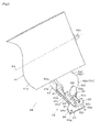
Fig. 4 is a cross-sectional view showing the second reflector and a required portion of a housing according to the same embodiment. - Fag. 5 is a perspective view showing a power transmitted member and a power transmission device according to the same embodiment.
-
Fig. 6 is a cross - sectional view showing the positional relationship among drive means, a moving member, and the power transmitting member in the power transmission device according so the same embodiment. - Referring now to the attached drawings, an embodiment in which a transmitting device in the present invention is applied to a second reflector provided, for example, in a head-up display apparatus a vehicle will be described.
- The head-up display apparatus is an apparatus configured to display a virtual image V by causing display light L which is projected by a
display apparatus 12 as a display unit disposed in the interior of aninstrument panel 11 of avehicle 10 to reflect in the direction a driver (user) 14 of thevehicle 10 using afront glass 13 of thevehicle 10, which is a projecting member, as shown inFig 1 . In other words, the head-up display apparatus is configured to emit (project) the display light L emitted from a liquid crystal display, described later, of thedisplay apparatus 12 to (on) the front glass 13 (the projecting member) to allow theuser 14 to visually recognize the displayed image (virtual image) V obtained by this emission. Accordingly, theuser 14 is able to observe the virtual image V and the landscape in superimposed manner. - The
display apparatus 12 mainly includes aliquid crystal display 20, afirst reflector 30, asecond reflector 40, and ahousing 50 as shown inFig. 2 . - The
liquid crystal display 20 mainly includes alight source 21 having a light-emitting diode mounted on a wiring substrate R, and a TFT-type liquid crystal display element (display element) 22 positioned on the front side (right above) of thelight source 21 so as to allow passage of an illuminating light emitted from thelight source 21 to form the display light L. This means that thelight source 21 is disposed behind (wight below) the liquidcrystal display element 22, and the liquidcrystal display element 22 displays predetermined information (information to be displayed, described later) by the illuminating light emitted from thelight source 21. Theliquid crystal display 20 as described above is provided in thehousing 50 in such a manner that the surface thereof on the side where the display light L is emitted opposes a cold mirror, described later, of thefirst reflector 30, and is fixed and held at the position and orientation so that the optical axis of the display light L intersects the cold mirror. - The liquid
crystal display element 22 displays the information to be displayed (for example, the vehicle speed or the number of revolutions of an engine) by an element drive circuit, not shown, in numerical values or the like by emitting light. Theliquid crystal display 20 is configured to output the display light L made up of a light in a visible wavelength band, and thelight source 21 which emits, for example, red light (mainly, the wavelength band of emitted light; 610 to 640 nm) can be applied thereto. The information to be displayed is not limited to the vehicle speed and the number of revolutions of the engine, but it is needless to say that any display modes can be employed. - The
first reflector 30 includes acold mirror 31, and amounting member 32 configured to mount and fix thecold mirror 31 using predetermined mounting means. Thecold mirror 31 includes a substantiallyrectangular glass substrate 31a, and a first reflectinglayer 31b formed on one surface (the surface opposing a concave mirror of thesecond reflector 40, described later) of theglass substrate 31a. The first reflectinglayer 31b as described above includes a number of layers of interference films having different film thicknesses, and is formed using a method such as deposition. Thecold mirror 31 is disposed in an inclined state at a position to reflect the display light L emitted from theliquid crystal display 20 toward the second reflector 40 (above-described concave mirror). - The
cold mirror 31 reflects the light in the visible wavelength band (450 to 750 nm) including the wavelength band of the emitted light from theliquid crystal display 20 at a high reflectance ratio (for example, 80% or more), and reflects the light other than the light in the above-described visible wavelength band at a low reflectance ratio. Thecold mirror 31 applied in this case reflects lights out of the visible wavelength band, specifically, lights in infrared wavelength band (caloric ray or heat ray of sunlight) at the low reflectance ratio (for example, 15% or less). The light, which is not reflected by the first reflectinglayer 31b, is allowed to pass through thecold mirror 31. - In the case of this embodiment, the
cold mirror 31 and theliquid crystal display 20 are disposed at positions which cannot be viewed directly from a translucent cover, described later, of thehousing 50, so as not to be directly exposed to light from the outside (outside light) such as the sunlight. Themounting member 32 is formed of synthetic resin in, for example, black color, and is fixed to thehousing 50. - The
second reflector 40 includes a concave mirror (reflecting member) 41 configured to reflect the display light L from the cold mirror 31 (that is, the liquid crystal display element 22), amirror holder 42 configured to hold theconcave mirror 41, and apower transmission device 43 configured to transmit a power to a suspending portion, described later, of themirror holder 42 so as to adjust the angular position (disposed position) of themirror holder 42, as shown inFig 2 to Fig 4 . - The
concave mirror 41 is formed by depositing a second reflectinglayer 41a on a resin substrate formed of polycarbonate having a depressed surface. Theconcave mirror 41 as described above is disposed in an inclined state at a position where the second reflectinglayer 41a thereof opposes thecold mirror 31 and the translucent cover and can be viewed from the translucent cover. - The
concave mirror 41 is configured to reflect (project) the display light L from thecold mirror 31 toward the translucent cover (thefront glass 13 of the vehicle 10) while enlarging the scale thereof. This means that theconcave mirror 41 enlarges the display light L reflected by thecold mirror 31 and projects the enlarged display light L to thefront glass 13 via the translucent cover. - The
mirror holder 42 is formed of synthetic resin material, and includes ashaft member 42a in a substantially column shape axially supported by a bearing portion (not shown) provided in thehousing 50. Themirror holder 42 as described above includes holdingportions 42b each having a wall portion for holding theconcave mirror 41. In this case, double coated tapes (not shown) are interposed between theconcave mirror 41 and theholding portions 42b so that theconcave mirror 41 is fixedly held by theholding portions 42b. Themirror holder 42 and theconcave mirror 41 held thereby have a configuration which is movable in angle (rotatable) about an axis of rotary movement RA as a center axis of theshaft member 42a. -
Reference numeral 42c designates a projecting strip formed under theconcave mirror 41 so as to project in a substantially L-shape from behind theconcave mirror 41 toward the second reflectinglayer 41a, and the projectingstrip 42c includes atongue strip 42d and a suspendingportion 42e, and is integrally formed with themirror holder 42. The suspendingportion 42e of the projectingstrip 42c provided on themirror holder 42 corresponds to a power transmitted member according toClaim 1 in the present application. - The
tongue strip 42d inFig. 4 is formed of a substantially rectangular flat panel extending from a bottom surface portion 42f, which constitutes the bottom wall of the holdingportions 42b of themirror holder 42 toward the second reflectinglayer 41a (that is, extending substantially along the direction of the axis of a lead screw portion, described later). - The suspending
portion 42e as the power transmitted member includes an upright wall portion of a substantially rectangular flat panel shape, which is formed continuously from thetongue strip 42d so as to be suspended downward from a distal end portion of thetongue strip 42d (the side of the lead screw portion). The suspendingportion 42e as described above is sandwiched between first and second projecting portions in such a manner that bothsurfaces Fig. 4 come into point contact with a pair of the first and second projecting portions of the power transmitting member, described later, provided on thepower transmission device 43. - The
power transmission device 43 mainly includes a drive means 61, a supportingmember 62, a movingmember 63, aguide shaft 64, apower transmitting member 65, and anoscillation preventing member 66, and is used for rotating themirror holder 42 about the axis of rotary movement RA to adjust the angular position of the mirror holder 42 (concave mirror 41) (that is, to adjust the direction of projection of the display light L) as shown inFig. 3 to Fig. 5 . - The drive means 61 includes a stepping motor (driving member) 61a as a known PM-type (Permanent Magnet type) stepping motor which generates a rotational drive force by energizing, and a revolving
shaft 61b extending from the steppingmotor 61a. In this case, the revolvingshaft 61b includes alead screw portion 61c having a thread groove formed on the peripheral surface thereof in a spiral shape, which is rotationally driven in association with the drive of the steppingmotor 61a. In other words, thelead screw portion 61c (revolvingshaft 61b) as described above is configured to be rotationally driven upon receipt of the rotational drive force from the steppingmotor 61a. - In
Fig. 5 ,reference numeral 70 designates a controller composed of a microcomputer including ROM, RAM, and CPU, and the steppingmotor 61a is driven on the basis of a command signal (drive signal) from thecontroller 70. The drive signal supplied from thecontroller 70 is supplied to amotor drive circuit 71 connected to thecontroller 70. - Upon receipt of an operation signal supplied from a push-button switch (operating means), not shown, operated by the
user 14 for example, thecontroller 70 supplies the drive signal to themotor drive circuit 71 in order to move thepower transmitting member 65 to a predetermined set position according to the operation signal. Then, themotor drive circuit 71 having received the drive signal supplies a signal to drive the steppingmotor 61a, whereby the steppingmotor 61a is driven and thelead screw portion 61c is rotationally driven in association with the drive of the steppingmotor 61a. - The supporting
member 62 is formed of a metallic motor case which fixedly supports the steppingmotor 61a in an immovable state, is formed into a substantially U-shape in cross-section, and includes a substantially plate-shapedflat panel portion 62a disposed so as to extend along an axial direction X of thelead screw portion 61c, and a pair of first andsecond flange portions flat panel portion 62a extending along the axial direction X so as to correspond to the steppingmotor 61a. - The
first flange portion 62b positioned on the side of the steppingmotor 61a is formed with a throughhole 62d which allows penetration of an end portion (terminal end portion) 61d oft thelead screw portion 61c and a firstfitting hole 62e which allows fitting of one end portion of theguide shaft 64. Thefirst flange portion 62b and the required portion of the steppingmotor 61a are fixed to each other with predetermined mounting means, whereby the steppingmotor 61a is fixedly supported by the supportingmember 62 in the immovable state. - In contrast, the side of the
second flange portion 62c which is paired with thefirst flange portion 62b is formed with a hole (not shown) corresponding to the throughhole 62d and a secondfitting hole 62f corresponding to the firstfitting hole 62e to allow fitting of the other end portion of theguide shaft 64. A bearing member G is fitted to the hole provided on thesecond flange portion 62c. Then, a portion ofdistal end portion 61e of thelead screw portion 61c which is positioned on the side of the distal end of the projecting portion projecting on the side of the bearing member G penetrating through the throughhole 62d is axially supported by the bearing member G so as to be rotatable. -
Reference numerals oscillation preventing member 66 for tightening threaded portions of screws S1 which penetrate through the first and second screw holes. The first and secondscrew tightening portions flat panel portion 62a so as to project into a substantially cylindrical shape on the side of the front surface of theflat panel portion 62a, and, more specifically, the firstscrew tightening portion 62g is provided in the vicinity of thefirst flange portion 62b and the secondscrew tightening portion 62h is provided in the vicinity of thesecond flange portion 62c. - The moving
member 63 is formed of a nut screwed onto (engaged with) a predetermined portion of thelead screw portion 61c of the revolvingshaft 61b, and is configured to move along the axial direction X of thelead screw portion 61c on thelead screw portion 61c by a thrust given by the rotation of thelead screw portion 61c. In this case, the movingmember 63 is configured to move (reciprocate) to thedistal end portion 61e or to theterminal end portion 61d of thelead screw portion 61c by thelead screw portion 61c being rotationally driven. - The
guide shaft 64 is formed of, for example, an elongated cylindrical metallic material, and is fitted at one end portion thereof into the firstfitting hole 62e of the supportingmember 62 and at the other end portion thereof into the secondfitting hole 62f of the supportingmember 62 so as to be substantially in parallel to thelead screw portion 61c (revolvingshaft 61b) . - The
power transmitting member 65 is formed of synthetic resin material such as polyacetal and includes abase portion 65a and a pair of first and secondopposed walls surface portion 65b of thebase portion 65a so as to oppose to each other. - The
base portion 65a includes an insertion portion 65e having a substantially circular through hole shape for allowing insertion of theguide shaft 64, and a pair of first and second abuttingportions second side surfaces Fig 6 ) In this case, the first and second abuttingportions base portion 65a so as to partially sandwich the first andsecond side surfaces member 63. - In this case, the surface of the moving
member 63 on the side of thefirst flange portion 62b is thefirst side surface 63a, and the surface of the same on the side of thesecond flange portion 62c is thesecond side surface 63b. The firstabutting portion 65f is in abutment with thefirst side surface 63a and the second abuttingportion 65g is in abutment with thesecond side surface 63b, whereby the movingmember 63 is sandwiched between the first and second abuttingportions - The first and second
opposed walls portions 65h, 65i which come respectively into point contact with the suspendingportion 42e (bothsurfaces strip 42c of themirror holder 42 on the distal end sides thereof. - The first and second projecting
portions 65h, 65i as described above each have a substantially semicircular shape, and are formed so as to sandwich the suspendingportion 42e so as to allow vertex portions thereof to come into point contact with the bothsurfaces portion 42e. In other words, the first projectingportion 65h and the second projecting portion 65i are arranged so as to oppose to each other with a predetermined gap provided therebetween, and the suspending portion (power transmitted member) 42e is interposed in the gap so that the first and second projectingportions 65h, 65i and the bothsurfaces - The
oscillation preventing member 66 is formed of soft synthetic resin material (for example, polypropylene resin), and includes a substantially rectangular flat-panel shapedbase portion 66a provided so as to correspond to theflat panel portion 62a of the supportingmember 62. Theoscillation preventing member 66 as described above is provided with an oscillation attenuating function which attenuates oscillation generated when the steppingmotor 61a is driven while it is transmitted from the supportingmember 62 to thehousing 50. - A
first lug portion 66b is formed so as to project sideward of thebase portion 66a at a first corner C1 provided at a position corresponding to a first boss portion, described later, of thehousing 50 from among four corners of thebase portion 66a of theoscillation preventing member 66 so as to have the substantially same thickness as that of thebase portion 66a. Asecond lug portion 66c is formed so as to project sideward of thebase portion 66a at a second corner C2 provided in the direction of the diagonal line with respect to the first corner C1 and at a position corresponding to a second boss portion, described later, of thehousing 50 so as to have the substantially same thickness as that of thebase portion 66a. -
Reference numerals screw tightening portions member 62, respectively, and are formed of through holes for allowing penetration of the threaded portions of the screws S1 therethrough from the back side of thebase portion 66a. The first andsecond screw holes base portion 66a, thefirst screw hole 66d is provided on the side of thefirst flange portion 62b and thesecond screw hole 66e is provided on the side of thesecond flange portion 62c. - Then, the fixation between the
oscillation preventing member 66 and the supportingmember 62 is completed by penetrating the threaded portions of the screws S1 through the first andsecond screw holes base portion 66a, and tightening the required portions of the threaded portions of the screws S1 penetrated through therespective screw holes screw tightening portions member 62 and theoscillation preventing member 66 are fixed with the screws S1 -
Reference numeral 66f designates a third screw hole provided so as to be connected with a third screw tightening portion, described later, provided on the first boss portion, and is formed of a through hole for allowing penetration of a threaded portion of a screw S2 therethrough from the front side of thebase portion 66a, and thethird screw hole 66f as described above is formed at a predetermined position of thefirst lug portion 66b. - In the same manner,
reference numeral 66g designates a fourth screw hole provided so as to be connected with a fourth screw tightening portion, described later, provided on the first boss portion, and is formed of a through hole for allowing penetration of the threaded portion of the screw S2 therethrough from the front side of thebase portion 66a, and thefourth screw hole 66g as described above is formed at a predetermined position of thesecond lug portion 66c. - In the
power transmission device 43 configured as described above, when thelead screw portion 61c is rotationally driven upon receipt of the rotational drive force from the steppingmotor 61a, the movingmember 63 engaged with thelead screw portion 61c reciprocates along the axial direction X. Then, for example, when the movingmember 63 is moved toward thefirst flange portion 62b, a thrust to move the first abuttingportion 65f which is in surface contact therewith toward thefirst flange portion 62b is applied to thefirst side surface 63a of the movingmember 63. - With the action of the thrust as described above, the
power transmitting member 65 moves toward thefirst flange portion 62b in parallel along the axial direction X synchronously with the movement of the movingmember 63 in a state of being guided by theguide shaft 64. Then, in association with the parallel movement of thepower transmitting member 65, a power to rotate themirror holder 42 is transmitted to the suspendingportion 42e, which is the power transmitted member interposed between the respective projectingportions 65h, 65i of thepower transmitting member 65. In this case, with the power transmission to the suspendingportion 42e, themirror holder 42 rotates in the direction indicated by an arrow inFig. 4 about the axis of rotary movement - In other words, the
power transmitting member 65 in this example is intended to be moved along the axial direction X of thelead screw portion 61c by the rotational driving of thelead screw portion 61c, and transmit the power to the suspending portion (power transmitted member) 42e of themirror holder 42. Then, by moving the angular position of the mirror holder 42 (concave mirror 41) about the axis of rotary movement RA by the power transmission to the suspendingportion 42e, the direction of projection of the displays light L with respect to thefront glass 13 is adjusted and, in association with this, the position of the display image V which is visible for theuser 14 can be moved up and down (vertical direction) on thefront glass 13. - In addition, in this example, when the stepping
motor 61a is driven on the basis of the drive signal, thelead screw portion 61c is rotationally driven, and thepower transmitting member 65 moves along the axial direction X and, at a time point when the movement (positional adjustment) of thepower transmitting member 65 is completed, thecontroller 70 does not output the drive signal to the steppingmotor 61a. In other words, thecontroller 70 is configured to control the output of the drive signal to the steppingmotor 61a to be stopped when thepower transmitting member 65 is not moved along the axial direction X. It is needless to say that thepower transmitting member 65 is strongly held by thelead screw portion 61c while the output of the drive signal is stopped because the movingmember 63 formed of a nut is tightened onto thelead screw portion 61c formed with the screw groove. - therefore, since the
power transmitting member 65 is strongly held by thelead screw portion 61c and the drive signal is not supplied to the steppingmotor 61a (that is, no electric current is supplied to the exciting coil, not shown, provided of the steppingmotor 61a) after having adjusted the disposed position of thepower transmitting member 65 to the predetermined position, the heat radiation value that generated by the steppingmotor 61a can be reduced in comparison with that in the related art. - It is needless to say that the
power transmitting member 65 moves toward thesecond flange portion 62c in parallel when the movingmember 63 moves toward thesecond flange portion 62c instead of thefirst flange portion 62b, whereby a power to rotate themirror holder 42 about the axis of rotary movement RA in the direction opposite from the direction of the arrow indicated inFig. 4 on the suspendingportion 42e. - The
housing 50 is formed using, for example, an aluminum die casting and includes anupper case member 51 and alower case member 52 both having a substantially depressed shape in cross-section, and is configured to accommodate theliquid crystal display 20, thefirst reflector 30, and thesecond reflector 40 in aspace 53 as an internal space defined by theupper case member 51 and the lower case member 52 (seeFig. 2 ) . - The
upper case member 51 is formed with anopening window 51a opening above the position where theconcave mirror 41 is disposed (on the side of thefront glass 13 of the vehicle 10) , and atranslucent cover 54 which corresponds to an light-output portion is disposed on theopening window 51a so as to close theopening window 51a. - The
translucent cover 54 as described above is formed of translucent synthetic resin material (for example, acrylic resin), and has a function as a light-translucent member which allows transmission (passage) of the display light L reflected by theconcave mirror 41. In other words, the display light L reflected by theconcave mirror 41 is projected on thefront glass 13 through thetranslucent cover 54 formed on thehousing 50, whereby the display of the virtual image V is achieved. - In contrast, a pair of first and
second boss portions oscillation preventing member 66 as shown inFig. 4 are provided on the bottom portion of thelower case member 52. - The
first boss portion 52a includes a third screw tightening portion 52c for tightening the screw S2 therein, and the third screw tightening portion 52c as described above is in communication with thethird screw hole 66f provided through theoscillation preventing member 66. In contrast, thesecond boss portion 52b includes a fourthscrew tightening portion 52d for tightening the screw S2 therein, and the fourthscrew tightening portion 52d as described above is in communication with thefourth screw hole 66g provided through theoscillation preventing member 66. - Then, the fixation between the
oscillation preventing member 66 and the housing 50 (respective boss portions fourth screw holes base portion 66a, and tightening the required portions of the threaded portions of the screws S2 penetrated through therespective screw holes screw tightening portions 52c, 52d provided in therespective boss portions oscillation preventing member 66 and the housing 50 (respective boss portions - As described above, in this embodiment, the stepping
motor 61a configured to be driven on the basis of the drive signal from thecontroller 70, thelead screw portion 61c configured to be rotationally driven in association with the drive of the steppingmotor 61a, and thepower transmitting member 65 configured to be moved along the axial direction X of thelead screw portion 61c by the rotation of thelead screw portion 61c and transmit the power to the suspendingportion 42e as the power transmitted member, and thecontroller 70 is configured to control the output of the drive signal to the steppingmotor 61a to be stopped when thepower transmitting member 65 is not moved along the axial direction X. - Therefore, since the power transmitting member. 65 is strongly held by the
lead screw portion 61c and the drive signal is not supplied to the steppingmotor 61a (that is, no electric current is supplied to the exciting coil provided on the steppingmotor 61a) after having adjusted the disposed position of thepower transmitting member 65 to the predetermined position, the heating value that the steppingmotor 61a by itself generates can be reduced in comparison with that in the related art. Therefore, according to the present invention, since the heat radiation value that generated by the steppingmotor 61a can be reduced in comparison with that in the related art, the possibility of breakage of the stepping motor due to the heat generation of the stepping motor is eliminated. - In this embodiment, an example in which the moving
member 63 which is engaged with thelead screw portion 61c and is configured to move along the axial direction X of thelead screw portion 61c by the rotation of thelead screw portion 61c is provided, and thepower transmitting member 65 moves along the axial direction X synchronously with the movement of the movingmember 63 to transmit the power to the suspending portion (power transmitted member) 42e has been described. However, for example, a configuration in which the movingmember 63 is eliminated, and the required portion of thepower transmitting member 65 and thelead screw portion 61c are engaged with each other, and thepower transmitting member 65 moves along the axial direction X of thelead screw portion 61c by the rotation of thelead screw portion 61c to transmit the power to the suspendingportion 42e is also applicable. - In this embodiment, an example in which the power is transmitted to the suspending
portion 42e using thepower transmission device 43 to adjust the angular position of the mirror holder 42 (concave mirror 41) is described. However, a configuration in which thepower transmission device 43 is employed in the above-describedliquid crystal display 20, for example, is also applicable. - Specifically, although the detailed illustration in the drawings is omitted, a configuration in which a window portion which allows passage of the illuminating light emitted from the
light source 21 is provided, a predetermined portion of a movable supporting member on which the liquidcrystal display element 22 is placed (supported) (for example, a flange portion having an upright shape extending outward of the movable supporting member) is positioned between the first and second projectingportions 65h, 65i of thepower transmitting member 65 described above, the power is transmitted to the predetermined portion (the flange portion) as the power transmitted member by the movement of thepower transmitting member 65, and the movable supporting member (liquid crystal display element 22) is rotated clockwise or counterclockwise with reference to the predetermined position to adjust the disposed position of the liquidcrystal display element 22 in theliquid crystal display 20 is also applicable. In this configuration, the inclination of the virtual image V with respect to the front glass 13 (that is, the inclination of the virtual image V that is visually recognizable by theuser 14 with respect to a virtual horizontal line) can be adjusted. - The present invention can be applied to the power transmission device which is configured to transmit the power to the mirror holder which holds the reflecting member such as the concave mirror provided on the head-up display apparatus for a vehicle and adjust the angular positions of the reflecting member.
-
- 40
- second reflector
- 41
- concave mirror (reflecting member)
- 42
- mirror holder
- 42e
- suspending portion (power transmitted member)
- 43
- power transmission device
- 61
- drive means
- 61a
- stepping motor (driving member)
- 61c
- lead screw portion
- 62
- supporting member
- 63
- moving member
- 64
- guide shaft
- 65
- power transmitting member
- 66
- oscillation preventing member
- 70
- controller
- RA
- of rotary movement
- X
- direction
Claims (3)
- A power transmission device comprising:a driving member configured to be driven on the basis of a command signal from a controller;a lead screw portion configured to be rotationally driven in association with the drive of the driving member; anda power transmitting member configured to move along an axial direction of the lead screw portion in accordance with the rotation of the lead screw portion to transmit the power to a power transmitted member,characterized in that the controller is configured to control the output of the command signal to the driving member to be stopped when the power transmitting member is not moved along the axial direction.
- The power transmission device according to Claim 1, comprising a moving member configured to be engaged with the lead screw portion and move along the axial direction in accordance with a thrust given by the rotation of the lead screw portion,
characterized in that the power transmitting member moves along the axial direction synchronously with the movement of the moving member. - The power transmission device according to Claim 1, characterized in that the power transmitting member is formed with an insertion portion configured to allow insertion of a guide shaft, which extends in substantially parallel to the lead screw portion.
Applications Claiming Priority (2)
| Application Number | Priority Date | Filing Date | Title |
|---|---|---|---|
| JP2008136476A JP5348459B2 (en) | 2008-05-26 | 2008-05-26 | Power transmission device used for vehicle head-up display device |
| PCT/JP2009/058614 WO2009145036A1 (en) | 2008-05-26 | 2009-05-07 | Power transmission device |
Publications (2)
| Publication Number | Publication Date |
|---|---|
| EP2287496A1 true EP2287496A1 (en) | 2011-02-23 |
| EP2287496A4 EP2287496A4 (en) | 2016-10-12 |
Family
ID=41376922
Family Applications (1)
| Application Number | Title | Priority Date | Filing Date |
|---|---|---|---|
| EP09754544.6A Withdrawn EP2287496A4 (en) | 2008-05-26 | 2009-05-07 | Power transmission device |
Country Status (6)
| Country | Link |
|---|---|
| US (1) | US8864325B2 (en) |
| EP (1) | EP2287496A4 (en) |
| JP (1) | JP5348459B2 (en) |
| KR (1) | KR101698609B1 (en) |
| CN (1) | CN102047006B (en) |
| WO (1) | WO2009145036A1 (en) |
Cited By (6)
| Publication number | Priority date | Publication date | Assignee | Title |
|---|---|---|---|---|
| WO2013089276A3 (en) * | 2011-12-15 | 2014-03-13 | Yazaki Corporation | Head-up display device |
| WO2017077035A1 (en) * | 2015-11-06 | 2017-05-11 | Continental Automotive Gmbh | Head up display |
| FR3050040A1 (en) * | 2016-04-12 | 2017-10-13 | Valeo Comfort & Driving Assistance | IMAGE PROJECTION DEVICE FOR HIGH HEAD DISPLAY, ASSOCIATED HIGH HEAD DISPLAY AND METHOD FOR MANUFACTURING SUCH IMAGE PROJECTION DEVICE |
| EP3232250A4 (en) * | 2014-12-09 | 2018-09-12 | Nippon Seiki Co., Ltd. | Head-up display device |
| EP3683615A1 (en) * | 2019-01-18 | 2020-07-22 | Continental Automotive GmbH | A head-up display device for a vehicle and vehicle |
| DE102019132417B4 (en) | 2018-12-05 | 2023-08-17 | Nidec Sankyo Corporation | DRIVE DEVICE AND HEAD-UP DISPLAY DEVICE |
Families Citing this family (27)
| Publication number | Priority date | Publication date | Assignee | Title |
|---|---|---|---|---|
| JP5064192B2 (en) * | 2007-12-04 | 2012-10-31 | スタンレー電気株式会社 | Optical axis adjustment device for vehicle headlamp |
| JP2009168098A (en) * | 2008-01-15 | 2009-07-30 | Jtekt Corp | Ball screw device |
| JP5348459B2 (en) * | 2008-05-26 | 2013-11-20 | 日本精機株式会社 | Power transmission device used for vehicle head-up display device |
| CN103119497B (en) * | 2010-09-17 | 2015-04-29 | 约翰逊控股公司 | Arrangement for mounting carriers for projection screens of head-up-displays |
| KR101259032B1 (en) * | 2011-03-17 | 2013-04-29 | 삼성중공업 주식회사 | Apparatus for controlling rectitude position for gantry machines |
| JP5890164B2 (en) * | 2011-12-15 | 2016-03-22 | 矢崎総業株式会社 | Head-up display device |
| JP5464222B2 (en) | 2012-02-08 | 2014-04-09 | 株式会社デンソー | Head-up display device for vehicle |
| JP5917257B2 (en) * | 2012-04-19 | 2016-05-11 | 矢崎総業株式会社 | Head-up display device |
| JP6107047B2 (en) * | 2012-10-24 | 2017-04-05 | 日本精機株式会社 | Head-up display device |
| JP6107380B2 (en) * | 2013-04-25 | 2017-04-05 | 日本精機株式会社 | Head-up display device |
| KR102253005B1 (en) | 2014-11-19 | 2021-05-17 | 현대모비스 주식회사 | Driving Module for Head-UP Display Device |
| KR102466609B1 (en) * | 2015-09-15 | 2022-11-14 | 엘지이노텍 주식회사 | Motor |
| KR102293579B1 (en) * | 2015-12-10 | 2021-08-26 | 현대모비스 주식회사 | Rotating drive apparatus |
| US20190146218A1 (en) * | 2016-05-10 | 2019-05-16 | Nippon Seiki Co., Ltd. | Head-up display device |
| KR102606984B1 (en) * | 2016-08-11 | 2023-11-29 | 엘지이노텍 주식회사 | Actuator and vehicle steering system having the same |
| CN107870421A (en) * | 2016-09-27 | 2018-04-03 | 上海蔚兰动力科技有限公司 | The adjustable reflector of head-up display device and include its head-up display device |
| KR101912648B1 (en) | 2017-06-02 | 2018-10-29 | 콘티넨탈 오토모티브 게엠베하 | Operating device foe head up display |
| DE102017116415B4 (en) | 2017-07-20 | 2024-03-28 | Valeo Schalter Und Sensoren Gmbh | Head-up display device for a motor vehicle with a coupling element of a rotatable mirror guided in a guide slot of a displaceable carriage, and motor vehicle |
| JP7053201B2 (en) * | 2017-09-15 | 2022-04-12 | 日本電産サンキョー株式会社 | Drive |
| CN109955794B (en) * | 2017-12-22 | 2021-10-15 | 光宝电子(广州)有限公司 | Inclination angle adjusting mechanism of head-up display device |
| US10684473B2 (en) * | 2017-12-22 | 2020-06-16 | Lite-On Electronics (Guangzhou) Limited | Angle-adjusting mechanism of head-up display |
| TWI675162B (en) * | 2018-06-22 | 2019-10-21 | 泓記精密股份有限公司 | Screw axial clearance adjustment mechanism |
| DE102018125709A1 (en) * | 2018-10-17 | 2020-04-23 | Dr. Ing. H.C. F. Porsche Aktiengesellschaft | Fastening system of a head-up display of a motor vehicle, head-up display for a motor vehicle, assembly template for a head-up display of a motor vehicle and teaching method for a head-up display of a motor vehicle |
| CN113330354B (en) * | 2019-01-25 | 2023-09-19 | 日本精机株式会社 | Head-up display device |
| JP2020117106A (en) * | 2019-01-25 | 2020-08-06 | 日本精機株式会社 | Driving device used in head-up display device and head-up display device |
| JP7172707B2 (en) * | 2019-02-20 | 2022-11-16 | 日本精機株式会社 | Mirror unit and head-up display device |
| JP7205284B2 (en) * | 2019-02-20 | 2023-01-17 | 日本精機株式会社 | Mirror device and head-up display device |
Family Cites Families (33)
| Publication number | Priority date | Publication date | Assignee | Title |
|---|---|---|---|---|
| JPS59132787A (en) * | 1983-01-17 | 1984-07-30 | Fuji Electric Co Ltd | Start/stop control circuit for motor |
| KR900006452B1 (en) * | 1988-06-03 | 1990-08-31 | 유재풍 | Rear view mirror |
| JPH0347662Y2 (en) * | 1989-03-28 | 1991-10-11 | ||
| JP2645487B2 (en) * | 1989-09-28 | 1997-08-25 | 株式会社 島津製作所 | Head-up display |
| JP2970051B2 (en) * | 1991-05-31 | 1999-11-02 | 日本精工株式会社 | Linear motion guide unit with integrated ball screw |
| US5499547A (en) * | 1991-09-04 | 1996-03-19 | Smc Kabushiki Kaisha | Actuator |
| WO1995006545A1 (en) * | 1993-09-02 | 1995-03-09 | Smc Kabushiki Kaisha | Actuator structure |
| US5649451A (en) * | 1994-06-30 | 1997-07-22 | Ruland; Frederick W. | Compact mechanism for creating simultaneous rotary and linear motion |
| US5910192A (en) * | 1996-01-16 | 1999-06-08 | Tri-Tech., Inc. | Low-cost linear positioning device |
| JP3927285B2 (en) * | 1997-07-08 | 2007-06-06 | 日本トムソン株式会社 | Slide device |
| US5980052A (en) * | 1997-07-29 | 1999-11-09 | Thor; Leifur Hayden | Sun reflecting device |
| US5957798A (en) * | 1997-09-10 | 1999-09-28 | Gec-Marconi Aerospace Inc. | Fail-free actuator assembly |
| JPH11119147A (en) * | 1997-10-14 | 1999-04-30 | Asahi Optical Co Ltd | Head up display |
| US6038127A (en) * | 1998-02-27 | 2000-03-14 | Comarco Wireless Technologies, Inc. | Keypad assembly using a lead screw assembly for moving a curved member |
| JP2000098925A (en) * | 1998-07-22 | 2000-04-07 | Yazaki Corp | Reflection display device for vehicle |
| US6325518B1 (en) * | 1999-03-12 | 2001-12-04 | Donnelly Corporation | Extendable exterior rearview mirror assembly |
| JP3649667B2 (en) * | 2000-12-06 | 2005-05-18 | 株式会社椿本チエイン | Stopper type linear actuator |
| US6497539B2 (en) * | 2001-01-12 | 2002-12-24 | Vincent P. Marroncelli | Clamping device for a machine tool |
| JP2002303320A (en) * | 2001-04-06 | 2002-10-18 | Smc Corp | Manufacturing method of frame with guide |
| US6478436B1 (en) * | 2001-05-22 | 2002-11-12 | Eaton Corporation | Sensing mirror position in a powered mirror positioning system |
| JP2003335148A (en) * | 2002-05-20 | 2003-11-25 | Nippon Seiki Co Ltd | Vehicular display device |
| JP4436031B2 (en) * | 2002-05-31 | 2010-03-24 | 日産自動車株式会社 | Vehicle steering control device |
| DE10252443A1 (en) * | 2002-11-12 | 2004-05-27 | Trumpf Lasertechnik Gmbh | Laser beam deflection arrangement has drive element movable along second pivot axis, along which holder, connecting element can be moved relative to each other, coupled to holder or connecting element |
| CN2609201Y (en) * | 2003-03-14 | 2004-03-31 | 深圳市新峰凌实业有限公司 | Automatic telescopic device for car antenna |
| JP2005036899A (en) * | 2003-07-15 | 2005-02-10 | Smc Corp | Electric actuator |
| JP2005069323A (en) * | 2003-08-22 | 2005-03-17 | Sharp Corp | Feed screw method and feed screw mechanism |
| CN1260083C (en) * | 2003-12-12 | 2006-06-21 | 上海沪工汽车电器有限公司 | Pick-up head actuating unit for reversion |
| JP3871334B2 (en) * | 2003-12-26 | 2007-01-24 | 株式会社ツバキエマソン | Push-stop electric cylinder |
| JP4404715B2 (en) * | 2004-07-27 | 2010-01-27 | 矢崎総業株式会社 | Head-up display device and mirror-integrated cover unit used therefor |
| CN1945944A (en) * | 2005-10-09 | 2007-04-11 | 精工电子有限公司 | Step motor and electronic equipment |
| JP4675824B2 (en) * | 2006-05-15 | 2011-04-27 | カルソニックカンセイ株式会社 | Vehicle display device |
| JP5029880B2 (en) * | 2007-03-09 | 2012-09-19 | 日本精機株式会社 | Head-up display device |
| JP5348459B2 (en) * | 2008-05-26 | 2013-11-20 | 日本精機株式会社 | Power transmission device used for vehicle head-up display device |
-
2008
- 2008-05-26 JP JP2008136476A patent/JP5348459B2/en active Active
-
2009
- 2009-05-07 US US12/992,249 patent/US8864325B2/en active Active
- 2009-05-07 WO PCT/JP2009/058614 patent/WO2009145036A1/en active Application Filing
- 2009-05-07 CN CN200980119114.5A patent/CN102047006B/en not_active Expired - Fee Related
- 2009-05-07 KR KR1020107025931A patent/KR101698609B1/en active IP Right Grant
- 2009-05-07 EP EP09754544.6A patent/EP2287496A4/en not_active Withdrawn
Non-Patent Citations (1)
| Title |
|---|
| See references of WO2009145036A1 * |
Cited By (9)
| Publication number | Priority date | Publication date | Assignee | Title |
|---|---|---|---|---|
| WO2013089276A3 (en) * | 2011-12-15 | 2014-03-13 | Yazaki Corporation | Head-up display device |
| CN103998971A (en) * | 2011-12-15 | 2014-08-20 | 矢崎总业株式会社 | Head-up display device |
| US9244276B2 (en) | 2011-12-15 | 2016-01-26 | Yazaki Corporation | Head-up display device |
| EP3232250A4 (en) * | 2014-12-09 | 2018-09-12 | Nippon Seiki Co., Ltd. | Head-up display device |
| WO2017077035A1 (en) * | 2015-11-06 | 2017-05-11 | Continental Automotive Gmbh | Head up display |
| FR3050040A1 (en) * | 2016-04-12 | 2017-10-13 | Valeo Comfort & Driving Assistance | IMAGE PROJECTION DEVICE FOR HIGH HEAD DISPLAY, ASSOCIATED HIGH HEAD DISPLAY AND METHOD FOR MANUFACTURING SUCH IMAGE PROJECTION DEVICE |
| WO2017178566A1 (en) * | 2016-04-12 | 2017-10-19 | Valeo Comfort And Driving Assistance | Image projection device for a head-up display, associated head-up display and method for producing such an image projection device. |
| DE102019132417B4 (en) | 2018-12-05 | 2023-08-17 | Nidec Sankyo Corporation | DRIVE DEVICE AND HEAD-UP DISPLAY DEVICE |
| EP3683615A1 (en) * | 2019-01-18 | 2020-07-22 | Continental Automotive GmbH | A head-up display device for a vehicle and vehicle |
Also Published As
| Publication number | Publication date |
|---|---|
| CN102047006A (en) | 2011-05-04 |
| KR101698609B1 (en) | 2017-01-20 |
| WO2009145036A1 (en) | 2009-12-03 |
| KR20110010730A (en) | 2011-02-07 |
| US8864325B2 (en) | 2014-10-21 |
| JP5348459B2 (en) | 2013-11-20 |
| EP2287496A4 (en) | 2016-10-12 |
| JP2009281557A (en) | 2009-12-03 |
| US20110061482A1 (en) | 2011-03-17 |
| CN102047006B (en) | 2015-12-02 |
Similar Documents
| Publication | Publication Date | Title |
|---|---|---|
| EP2287496A1 (en) | Power transmission device | |
| JP4973961B2 (en) | Power transmission device used for vehicle head-up display device | |
| US8743296B2 (en) | On-vehicle display apparatus | |
| US6654177B2 (en) | Vehicle-use head-up display system | |
| US9551875B2 (en) | Headup display device | |
| JP5088683B2 (en) | Head-up display device | |
| JP5741251B2 (en) | Virtual image display device | |
| JP2015102700A (en) | Display device | |
| JP2015182635A (en) | Head-up display device | |
| JP2019066527A (en) | Virtual image display device | |
| JP5257159B2 (en) | Head-up display device | |
| WO2019208423A1 (en) | Head-up display device and method for assembling same | |
| JP6780524B2 (en) | Head-up display device | |
| JP2008224791A (en) | Head-up display device | |
| JP7377443B2 (en) | power transmission device | |
| JP7040989B2 (en) | Vehicle display system | |
| CN112433370B (en) | Driving device and head-up display device | |
| JP2019139128A (en) | Head-up display device | |
| US20150229195A1 (en) | Stepper motor | |
| WO2016027418A1 (en) | Vehicular head-up display device | |
| US20240012235A1 (en) | Display device for vehicle | |
| US20240012264A1 (en) | Display device for vehicle | |
| WO2016175032A1 (en) | Headup display device and method for assembling headup display device | |
| WO2021256456A1 (en) | Head-up display device | |
| WO2019163655A1 (en) | Headup display |
Legal Events
| Date | Code | Title | Description |
|---|---|---|---|
| PUAI | Public reference made under article 153(3) epc to a published international application that has entered the european phase |
Free format text: ORIGINAL CODE: 0009012 |
|
| 17P | Request for examination filed |
Effective date: 20101214 |
|
| AK | Designated contracting states |
Kind code of ref document: A1 Designated state(s): AT BE BG CH CY CZ DE DK EE ES FI FR GB GR HR HU IE IS IT LI LT LU LV MC MK MT NL NO PL PT RO SE SI SK TR |
|
| AX | Request for extension of the european patent |
Extension state: AL BA RS |
|
| DAX | Request for extension of the european patent (deleted) | ||
| RA4 | Supplementary search report drawn up and despatched (corrected) |
Effective date: 20160913 |
|
| RIC1 | Information provided on ipc code assigned before grant |
Ipc: F16H 25/20 20060101AFI20160907BHEP Ipc: G02B 27/01 20060101ALI20160907BHEP Ipc: H02P 8/24 20060101ALI20160907BHEP |
|
| 17Q | First examination report despatched |
Effective date: 20190425 |
|
| STAA | Information on the status of an ep patent application or granted ep patent |
Free format text: STATUS: THE APPLICATION IS DEEMED TO BE WITHDRAWN |
|
| 18D | Application deemed to be withdrawn |
Effective date: 20200603 |