WO2009128287A1 - 電動機 - Google Patents
電動機 Download PDFInfo
- Publication number
- WO2009128287A1 WO2009128287A1 PCT/JP2009/052780 JP2009052780W WO2009128287A1 WO 2009128287 A1 WO2009128287 A1 WO 2009128287A1 JP 2009052780 W JP2009052780 W JP 2009052780W WO 2009128287 A1 WO2009128287 A1 WO 2009128287A1
- Authority
- WO
- WIPO (PCT)
- Prior art keywords
- magnetic
- electric motor
- armature
- rotor
- phase
- Prior art date
Links
Images


Classifications
-
- H—ELECTRICITY
- H02—GENERATION; CONVERSION OR DISTRIBUTION OF ELECTRIC POWER
- H02K—DYNAMO-ELECTRIC MACHINES
- H02K21/00—Synchronous motors having permanent magnets; Synchronous generators having permanent magnets
- H02K21/12—Synchronous motors having permanent magnets; Synchronous generators having permanent magnets with stationary armatures and rotating magnets
-
- H—ELECTRICITY
- H02—GENERATION; CONVERSION OR DISTRIBUTION OF ELECTRIC POWER
- H02K—DYNAMO-ELECTRIC MACHINES
- H02K16/00—Machines with more than one rotor or stator
- H02K16/02—Machines with one stator and two or more rotors
-
- H—ELECTRICITY
- H02—GENERATION; CONVERSION OR DISTRIBUTION OF ELECTRIC POWER
- H02K—DYNAMO-ELECTRIC MACHINES
- H02K41/00—Propulsion systems in which a rigid body is moved along a path due to dynamo-electric interaction between the body and a magnetic field travelling along the path
- H02K41/02—Linear motors; Sectional motors
- H02K41/03—Synchronous motors; Motors moving step by step; Reluctance motors
-
- H—ELECTRICITY
- H02—GENERATION; CONVERSION OR DISTRIBUTION OF ELECTRIC POWER
- H02P—CONTROL OR REGULATION OF ELECTRIC MOTORS, ELECTRIC GENERATORS OR DYNAMO-ELECTRIC CONVERTERS; CONTROLLING TRANSFORMERS, REACTORS OR CHOKE COILS
- H02P21/00—Arrangements or methods for the control of electric machines by vector control, e.g. by control of field orientation
Definitions
- the present invention relates to an electric motor that has a plurality of movers or stators, converts supplied electric power into power, and outputs the power from the movers.
- This electric motor is a so-called rotating machine, and includes a first rotor and a second rotor connected to a first rotating shaft and a second rotating shaft, respectively, and a single stator.
- the first and second rotating shafts are arranged concentrically with each other, and the first rotor, the second rotor, and the stator are arranged in this order from the inside in the radial direction of the first rotating shaft.
- the first rotor has a plurality of first permanent magnets and second permanent magnets, each of which is aligned in the circumferential direction, and the first and second permanent magnets are aligned in parallel with each other in the axial direction of the first rotor. It is out.
- the stator is configured to generate a first rotating magnetic field and a second rotating magnetic field that rotate in the circumferential direction by the supply of electric power, and the first rotating magnetic field is a portion of the first rotor on the first permanent magnet side.
- the second rotating magnetic field is generated between the first rotor and the second permanent magnet side portion of the first rotor.
- the second rotor has a plurality of first cores and second cores that are arranged in the circumferential direction.
- the first and second cores are made of a soft magnetic material, the first core is disposed between the first permanent magnet side portion of the first rotor and the stator, and the second core is The first rotor is disposed between the second permanent magnet side portion and the stator.
- the magnetic poles of the first and second permanent magnets, the magnetic poles of the first and second rotating magnetic fields, and the numbers of the first and second cores are set to be the same.
- the first and second rotating magnetic fields and the first and second permanent magnets generate the first and second rotating magnetic fields as the first and second rotating magnetic fields are generated by supplying power to the stator.
- the first and second cores are magnetized, magnetic field lines are generated between these elements.
- the first and second rotors are driven by the action of the magnetic force of the magnetic field lines, and as a result, power is output from the first and second rotating shafts.
- the second soft magnetic body row made up of a plurality of second cores is indispensable, avoiding an increase in the size of the motor and an increase in manufacturing costs. I can't.
- the difference between the rotation speed of the first and second rotating magnetic fields and the rotation speed of the second rotor is the same as the difference between the rotation speed of the second rotor and the rotation speed of the first rotor. Therefore, the degree of freedom of design is low.
- the present invention has been made to solve the above-described problems, and an object of the present invention is to provide an electric motor that can reduce the size and the manufacturing cost and can increase the degree of design freedom.
- the electric motors 1 and 31 according to claim 1 are configured by a plurality of predetermined magnetic poles (permanent magnets 4a and 34a) arranged in a predetermined direction, and two adjacent magnetic poles have different polarities.
- armatures iron core 3a, U-phase
- first structure first rotor 4, first rotating shaft 6, second stator 34
- second structure second rotor 5, second rotating shaft 7
- magnetic body core 5 a, core 35 b
- soft magnetic body row disposed so as to be positioned between the magnetic pole row and the armature row.
- the soft magnetic material rows of the third structure are arranged so as to be positioned between the magnetic pole rows of the first structure and the armature rows of the second structure facing each other.
- a plurality of magnetic poles, armatures, and soft magnetic bodies that respectively constitute the magnetic pole array, the armature array, and the soft magnetic body array are arranged in a predetermined direction.
- a plurality of armature magnetic poles are generated with the supply of power to the armature array, and a moving magnetic field generated by these armature magnetic poles is generated between the armature magnetic pole array and moves in a predetermined direction.
- each two adjacent magnetic poles have different polarities, and there is a gap between each two adjacent soft magnetic bodies.
- the moving magnetic field is generated by the plurality of armature magnetic poles and the soft magnetic body row is arranged between the magnetic pole row and the armature row, the soft magnetic body is separated by the armature magnetic pole and the magnetic pole. Magnetized. Due to this and the gap between each two adjacent soft magnetic bodies as described above, magnetic lines of force connecting the magnetic pole, the soft magnetic body, and the armature magnetic pole are generated. Moreover, the electric power supplied to the armature is converted into power by the action of the magnetic force generated by the magnetic lines of force, and is output from the first structure, the second structure, and the third structure.
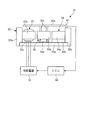
- FIG. 1 An equivalent circuit corresponding to the electric motor is shown as in FIG. (A)
- the motor is a rotating machine, and the armature has a U-phase, V-phase, and W-phase three-phase coil.
- B Two armature magnetic poles and four magnetic poles, that is, N poles of the armature magnetic pole And the number of pole pairs with one set of S poles is value 1, the number of pole pairs with one set of N poles and S poles of magnetic poles is value 2, and there are three soft magnetic bodies.
- “Pole pair” used in writing refers to a set of N and S poles.
- the magnetic flux ⁇ k1 of the magnetic pole passing through the first soft magnetic body among the soft magnetic bodies is expressed by the following formula (1).
- ⁇ f is the maximum value of the magnetic flux of the magnetic pole
- ⁇ 1 and ⁇ 2 are the rotation angle position of the magnetic pole and the rotation angle position of the soft magnetic material with respect to the U-phase coil.
- the ratio of the number of pole pairs of the magnetic poles to the number of pole pairs of the armature poles is 2.0, the magnetic flux of the poles rotates (changes) with a period twice that of the moving magnetic field.
- ( ⁇ 2 ⁇ 1) is multiplied by a value of 2.0 in order to express this.
- the magnetic flux ⁇ u1 of the magnetic pole passing through the U-phase coil via the first soft magnetic body is expressed by the following equation (2) obtained by multiplying equation (1) by cos ⁇ 2.
- the magnetic flux ⁇ k2 of the magnetic pole passing through the second soft magnetic body of the soft magnetic bodies is expressed by the following formula (3). Since the rotational angle position of the second soft magnetic body with respect to the armature is advanced by 2 ⁇ / 3 with respect to the first soft magnetic body, in the above equation (3), in order to express that, 2 ⁇ / 3 is added.
- the magnetic flux ⁇ u2 of the magnetic pole passing through the U-phase coil via the second soft magnetic body is expressed by the following equation (4) obtained by multiplying equation (3) by cos ( ⁇ 2 + 2 ⁇ / 3). .
- the magnetic flux ⁇ u3 of the magnetic pole passing through the U-phase coil via the third soft magnetic body of the soft magnetic bodies is expressed by the following equation (5).
- the magnetic flux ⁇ u of the magnetic poles passing through the U-phase coil via the soft magnetic material is the magnetic flux ⁇ u1 to ⁇ u3 expressed by the above equations (2), (4), and (5). Since it becomes what was added, it is represented by following Formula (6).
- the magnetic flux ⁇ u of the magnetic pole passing through the U-phase coil via the soft magnetic material is expressed by the following equation (7).
- a, b, and c are the number of pole pairs of the magnetic poles, the number of soft magnetic bodies, and the number of pole pairs of the armature magnetic poles, respectively.
- the second term on the right-hand side of the equation (10) is 0 as shown in the following equation (11) when arranged based on the sum of the series and Euler's formula on condition that ac ⁇ 0.
- the third term on the right side of the above equation (10) can be reduced to a value of 0 as shown in the following equation (12) when arranged based on the sum of the series and Euler's formula on condition that ac ⁇ 0. Obviously, the third term on the right side of the above equation (10) can be reduced to a value of 0 as shown in the following equation (12) when arranged based on the sum of the series and Euler's formula on condition that ac ⁇ 0. Become.
- ⁇ e2 represents the electrical angular position of the soft magnetic material with respect to the U-phase coil, as is apparent from multiplying the rotation angle position ⁇ 2 of the soft magnetic material with respect to the U-phase coil by the pole pair number c of the armature magnetic pole.
- ⁇ e1 represents the electrical angle position of the magnetic pole with respect to the U-phase coil, as is apparent from the fact that the rotation angle position ⁇ 1 of the magnetic pole with respect to the U-phase coil is multiplied by the pole pair number c of the armature magnetic pole.
- the magnetic flux ⁇ v of the magnetic pole passing through the V-phase coil through the soft magnetic material is advanced by the electrical angle 2 ⁇ / 3 with respect to the U-phase coil by the electrical angle position of the V-phase coil. 16). Further, the magnetic flux ⁇ w of the magnetic pole passing through the W-phase coil via the soft magnetic material is delayed by an electrical angle of 2 ⁇ / 3 with respect to the U-phase coil from the electrical angle position of the W-phase coil. ).
- ⁇ e1 is a time differential value of ⁇ e1, that is, a value obtained by converting an angular velocity of the first structure relative to the second structure into an electrical angular velocity
- ⁇ e2 is a time differential value of ⁇ e2, that is, the second structure. Is a value obtained by converting the angular velocity of the third structure to the electrical angular velocity.
- the magnetic flux that passes directly through the U-phase to W-phase coils without using a soft magnetic material is extremely small, and its influence can be ignored. Therefore, the time differential values d ⁇ u / dt to d ⁇ w / dt of the magnetic fluxes ⁇ u to ⁇ w (formulas (18) to (20)) of the magnetic poles passing through the U-phase to W-phase coils via the soft magnetic material are The counter electromotive voltages (inductive electromotive voltages) generated in the U-phase to W-phase coils as the magnetic poles and the soft magnetic material rotate (move) with respect to the child row are shown.
- Iu, Iv, and Iw flowing through the U-phase, V-phase, and W-phase coils are expressed by the following equations (21), (22), and (23), respectively.
- I is the amplitude (maximum value) of the current flowing through the U-phase to W-phase coils.
- the electric power supplied to the armature train and the torque equivalent to the electric angular velocity ⁇ mf of the moving magnetic field are the driving equivalent torque Te
- the power supplied to the armature train and the mechanical output W are equal to each other (however, the loss And the equivalent driving torque Te is expressed by the following equation (31).
- the following equation (32) is obtained.
- the relationship between the torque expressed by the equation (32) and the relationship between the electrical angular velocities expressed by the equation (25) are exactly the same as the relationship between the rotational speed and torque in the sun gear, ring gear, and carrier of the planetary gear device. .
- the relationship between the electrical angular velocity and the torque is not limited to the case where the above-described second structure is made immovable, and is established under any conditions regarding whether the first to third structures can be moved. .
- it is also established when electric power is supplied in a state where power is input to the second structure without configuring the second structure to be immovable.
- the first or third structure This is also true when the body is configured to be immovable or when power is supplied to the armature train in a state where power is input to the first or third structure.
- the second structure is configured to be movable, and the first and / or third structure is configured to be immovable, or power is input to the first and / or third structure. This is also true when power is supplied.
- the number of armature magnetic poles The ratio between the number of magnetic poles and the number of soft magnetic materials is 1: m: (1 + m) / 2.
- the fact that the above condition of ac ⁇ 0 is satisfied indicates that m ⁇ 1.0.
- the ratio of the number of armature magnetic poles, the number of magnetic poles, and the number of soft magnetic bodies is 1: m: (1 + m) / 2 (m ⁇ 1. 0)
- the relationship between the electrical angular velocities shown in the equation (25) and the torque relationship shown in the equation (32) are established, and it can be seen that the electric motor operates properly.
- the motor can be operated with only a single soft magnetic material row, so that the motor can be downsized and the manufacturing cost can be reduced.
- ⁇ a / c, that is, by setting the ratio of the number of pole pairs of the magnetic poles to the number of pole pairs of the armature magnetic poles, The relationship between the electrical angular velocities among the three structures and the relationship between the torques between the first to third structures can be freely set, so that the degree of freedom in designing the motor can be increased.
- relative positional relationship detecting means (first rotational position sensor 21, 1) for detecting the relative positional relationship of the first to third structures.
- Control means (ECU 16) for controlling the moving magnetic field based on the relative positional relationship between the second rotational position sensor 22, the electrical angle converter 16b, and the position sensor 41) and the detected first to third structures. And further comprising.
- the relative positional relationship detecting means detects the relative positional relationship between the three members of the first to third structures, and the detected three members of the first to third structures. Based on the relative positional relationship, the moving magnetic field is controlled by the control means. Thereby, since a magnetic force line can be appropriately generated between the magnetic pole, the soft magnetic material, and the armature magnetic pole, and the magnetic force by this magnetic force line can be appropriately applied, an appropriate operation of the electric motor can be ensured.
- the relative positional relationship detecting means (the first rotational position sensor 21, the second rotational position sensor 22, and the electrical angle converter 16b) is the first As the relative positional relationship of the third structure, the electrical angle positions of the first structure and the third structure with respect to the second structure are detected, respectively, and the control means detects the electrical structure of the detected third structure. Based on the difference between the value obtained by multiplying the angular position (second rotor electrical angle ⁇ ER2) by (1 + m) and the value obtained by multiplying the detected electrical angle position (first rotor electrical angle ⁇ ER1) of the first structure by m. The moving magnetic field is controlled.
- the moving magnetic field is controlled.
- m represents the ratio of the number of magnetic poles to the number of armature magnetic poles.
- ⁇ represents the ratio (a / c) of the number of magnetic pole pairs to the number of pole pairs of the armature magnetic poles, that is, the ratio of the number of magnetic poles to the number of armature magnetic poles, and is equal to m. Therefore, according to the configuration described above, a more appropriate operation of the electric motor can be ensured.
- the invention according to claim 4 is the electric motor 1, 31 according to any one of claims 1 to 3, characterized in that the magnetic pole is a magnetic pole of the permanent magnets 4a, 34a.
- a magnetic pole of a permanent magnet is used as a magnetic pole
- an electric circuit and a coil for supplying power to the electromagnet are not required unlike the case of using a magnetic pole of an electromagnet.
- the electric motor can be further reduced in size and the configuration can be simplified.
- a slip ring for supplying power when the magnetic poles of the electromagnet are used as the magnetic poles becomes unnecessary, and accordingly, the motor can be reduced in size. , Can increase efficiency.
- the invention according to claim 5 is the electric motor 1 according to claim 1, wherein the electric motor is a rotating machine.
- the invention according to claim 6 is the electric motor 31 according to claim 1, wherein the electric motor is a linear motor.
- FIG. 1 is a cross-sectional view schematically showing an electric motor according to a first embodiment of the present invention. It is a block diagram which shows the electric motor and ECU of FIG. It is a figure which expand
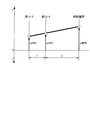
- FIG. 3 is a collinear diagram illustrating an example of a relationship between a magnetic field electrical angular velocity and first and second rotor electrical angular velocities in the electric motor of FIG. 1. It is a figure for demonstrating operation
- FIG. 6 is a diagram for explaining an operation subsequent to FIG. 5.
- FIG. 7 is a diagram for explaining an operation subsequent to FIG. 6. It is a figure for demonstrating the positional relationship of an armature magnetic pole and a core when an armature magnetic pole rotates only 2 electrical angle from the state shown in FIG. It is a figure for demonstrating operation
- FIG. 10 is a diagram for explaining an operation subsequent to FIG. 9. It is a figure for demonstrating the operation
- FIG. 17 is a plan view schematically showing a part of the electric motor of FIG. 16. It is a figure for demonstrating the relationship of the number of armature magnetic poles, cores, and magnet magnetic poles in the electric motor of FIG. It is a figure which shows the equivalent circuit of the electric motor of this invention.
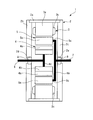
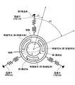
- FIG. 1 shows an electric motor 1 according to a first embodiment of the present invention.
- the electric motor 1 is configured as a rotating machine, and its operation is controlled by the ECU 16 shown in FIG.
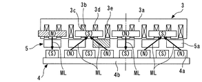
- the electric motor 1 includes a stationary case 2, a stator 3 provided in the case 2, a first rotor 4 provided in the case 2 so as to face the stator 3, and both 3 , 4, a second rotor 5, a first rotating shaft 6 and a second rotating shaft 7 are provided.
- some elements such as the first rotating shaft 6 are drawn in a skeleton diagram for convenience of illustration. Further, in FIG. 1 and other drawings described later, hatching of a portion showing a cross section is omitted.
- the case 2 has a cylindrical peripheral wall 2a and a pair of disk-shaped side walls 2b and 2c provided integrally at both ends of the peripheral wall 2a. Mounting holes 2d and 2e are formed in the center of these side walls 2b and 2c, respectively, and bearings 8 and 9 are mounted in these mounting holes 2d and 2e, respectively.
- the first and second rotating shafts 6 and 7 are rotatably supported by bearings 8 and 9, respectively, and are arranged concentrically with each other. Further, a part of each of the first and second rotating shafts 6 and 7 is accommodated in the case 2, and the rest protrudes outward of the case 2. Further, the stator 3, the second rotor 5 and the first rotor 4 are arranged in this order from the outside in the radial direction of the first rotating shaft 6 (hereinafter simply referred to as “radial direction”), and are concentrically arranged. Has been placed.
- the stator 3 generates a rotating magnetic field.
- the stator 3 includes an iron core 3a and U-phase, V-phase, and W-phase coils 3c, 3d, and 3e provided on the iron core 3a. is doing.
- the U-phase coil 3c is shown for convenience.
- the iron core 3 a has a cylindrical shape in which a plurality of steel plates are laminated, extends in the axial direction of the first rotating shaft 6 (hereinafter simply referred to as “axial direction”), and the inner peripheral surface of the peripheral wall 2 a of the case 2. Is attached.
- twelve slots 3b are formed on the inner peripheral surface of the iron core 3a, and these slots 3b extend in the axial direction and are connected to the circumferential direction of the first rotating shaft 6 (hereinafter simply referred to as “circumferential direction”). ”) At equal intervals.
- the U-phase to W-phase coils 3c to 3e are wound around the slot 3b by distributed winding (wave winding) and connected to the variable power source 15 (see FIG. 2).
- the variable power source 15 is a combination of an electric circuit including an inverter and a battery, and is connected to the ECU 16.
- stator 3 when power is supplied from the variable power source 15, four magnetic poles are generated at equal intervals in the circumferential direction at the end of the iron core 3a on the first rotor 4 side (FIG. 5).
- the rotating magnetic field generated by these magnetic poles rotates in the circumferential direction.
- the magnetic pole generated in the iron core 3a is referred to as “armature magnetic pole”.
- the polarities of the two armature magnetic poles adjacent to each other in the circumferential direction are different from each other.
- the armature magnetic poles are represented by (N) and (S) on the iron core 3a and the U-phase to W-phase coils 3c to 3e.
- the first rotor 4 has a magnetic pole row composed of eight permanent magnets 4a. These permanent magnets 4 a are arranged at equal intervals in the circumferential direction, and this magnetic pole row faces the iron core 3 a of the stator 3. Each permanent magnet 4 a extends in the axial direction, and the length in the axial direction is set to be the same as that of the iron core 3 a of the stator 3.
- the permanent magnet 4a is attached to the outer peripheral surface of the ring-shaped fixing portion 4b.
- the fixed portion 4b is made of a soft magnetic material, for example, iron or a laminate of a plurality of steel plates, and the inner peripheral surface of the fixed portion 4b is a disc-like shape that is concentrically provided integrally with the first rotating shaft 6. It is attached to the outer peripheral surface of the flange 4c. Thereby, the 1st rotor 4 containing the permanent magnet 4a can rotate integrally with the 1st rotating shaft 6.
- FIG. since the permanent magnet 4a is attached to the outer peripheral surface of the fixed portion 4b made of a soft magnetic material as described above, each permanent magnet 4a has (N) or (N One magnetic pole of S) appears. In FIG. 3 and other drawings to be described later, the magnetic poles of the permanent magnet 4a are represented by (N) and (S). The polarities of the two permanent magnets 4a adjacent to each other in the circumferential direction are different from each other.
- the second rotor 5 has a row of soft magnetic bodies composed of six cores 5a.
- the cores 5a are arranged at equal intervals in the circumferential direction, and the soft magnetic material rows are arranged at predetermined intervals between the iron core 3a of the stator 3 and the magnetic pole rows of the first rotor 4 respectively.
- Each core 5a is a soft magnetic material, for example, a laminate of a plurality of steel plates, and extends in the axial direction. Further, the length of the core 5a in the axial direction is set to be the same as that of the iron core 3a of the stator 3 like the permanent magnet 4a.
- the core 5a is attached to the outer end portion of the disc-shaped flange 5b via a cylindrical connecting portion 5c that extends slightly in the axial direction.
- the flange 5b is integrally and concentrically provided on the second rotating shaft 7.
- the second rotor 5 including the core 5a is rotatable integrally with the second rotating shaft 7.
- the connection part 5c and the flange 5b are abbreviate
- the electric motor 1 is provided with an electromagnetic induction type first rotational position sensor 21 and a second rotational position sensor 22.
- the first rotational position sensor 21 is a rotational angle position (hereinafter referred to as “first rotor rotational angle ⁇ R1”) of a specific permanent magnet 4a of the first rotor 4 with respect to a specific U-phase coil 3c (hereinafter referred to as “reference coil”) of the stator 3. )
- the second rotational position sensor 22 outputs to the ECU 16 a detection signal indicating the rotational angular position of the specific core 5a of the second rotor 5 with respect to the reference coil (hereinafter referred to as “second rotor rotational angle ⁇ R2”).
- the electric motor 1 is provided with a first current sensor 23 and a second current sensor 24.
- These first and second current sensors 23 and 24 respectively represent currents flowing through the U-phase and V-phase coils 3c and 3d (hereinafter referred to as “U-phase current Iu” and “V-phase current Iv”, respectively).
- a detection signal is output to the ECU 16.
- the ECU 16 is composed of a microcomputer composed of an I / O interface, CPU, RAM, ROM, and the like, and controls the operation of the electric motor 1 in accordance with detection signals from the various sensors 21 to 24 described above.
- the permanent magnet 4a corresponds to the magnetic pole in the present invention
- the first rotor 4 and the first rotating shaft 6 correspond to the first structure in the present invention
- the iron core 3a and the U-phase to W-phase coils 3c to 3e correspond to the armature in the present invention
- the stator 3 corresponds to the second structure in the present invention
- the core 5a corresponds to the soft magnetic body in the present invention
- the second rotor 5 and the second rotating shaft 7 correspond to the third structure in the present invention.
- the ECU 16 corresponds to the control means in the present invention
- the first and second rotational position sensors 21 and 22 correspond to the relative positional relationship detection means in the present invention.
- the electric motor 1 has four armature magnetic poles, eight magnetic poles of the permanent magnet 4a (hereinafter referred to as “magnet magnetic pole”), and six cores 5a. That is, the ratio of the number of armature magnetic poles, the number of magnet magnetic poles, and the number of cores 5a (hereinafter referred to as “pole number ratio”) is set to 1: 2.0: (1 + 2.0) / 2. As is clear from this and the equations (18) to (20) described above, the U-phase to W-phase coils 3c to 3c are rotated as the first rotor 4 and the second rotor 5 rotate with respect to the stator 3.
- I is the amplitude (maximum value) of the current flowing through the U-phase to W-phase coils 3c to 3e
- ⁇ F is the maximum value of the magnetic pole magnetic flux.
- ⁇ ER1 is a value obtained by converting the first rotor rotation angle ⁇ R1 that is a so-called mechanical angle into an electrical angle position (hereinafter referred to as “first rotor electrical angle”). Specifically, the first rotor rotation angle ⁇ R1 is set to an armature. This is a value obtained by multiplying the number of pole pairs of the magnetic poles, that is, the value 2.
- ⁇ ER2 is a value obtained by converting the second rotor rotation angle ⁇ R2, which is a mechanical angle, into an electrical angle position (hereinafter, referred to as “second rotor electrical angle”).
- the second rotor rotation angle ⁇ R2 includes an armature magnetic pole. It is a value obtained by multiplying the number of pole pairs (value 2).
- ⁇ ER1 is a time differential value of ⁇ ER1, that is, a value obtained by converting the angular velocity of the first rotor 4 with respect to the stator 3 into an electrical angular velocity (hereinafter referred to as “first rotor electrical angular velocity”).
- ⁇ ER2 is the second rotor electrical angular velocity, and is a time differential value of ⁇ ER2, that is, a value obtained by converting the angular velocity of the second rotor 5 with respect to the stator 3 into an electrical angular velocity (hereinafter referred to as “second rotor electrical angular velocity”). .
- the U-phase current Iu, the V-phase current Iv, and the current flowing through the W-phase coil 3e are expressed by the following equations (36), (37), and (38), respectively.
- magnetic field electric angle position ⁇ MFR The electrical angular velocity of the rotating magnetic field with respect to the stator 3 (hereinafter referred to as “magnetic field electrical angular velocity ⁇ MFR”) is represented by the following equation (40).
- the relationship between the magnetic field electrical angular velocity ⁇ MFR, the first rotor electrical angular velocity ⁇ ER1 and the second rotor electrical angular velocity ⁇ ER2 is represented by a so-called collinear diagram, for example, as shown in FIG.
- the electric power supplied to the stator 3 and the torque equivalent to the magnetic field electrical angular velocity ⁇ MFR is the driving equivalent torque TSE
- the driving equivalent torque TSE and the torque transmitted to the first rotor 4 hereinafter referred to as “first rotor”.
- transmission torque the torque transmitted to the second rotor 5
- second rotor transmission torque the torque transmitted to the second rotor 5
- the relationship between the electrical angular velocity represented by the above formula (40) and the torque represented by the above formula (41) are as follows: the sun gear, the ring gear and the sun gear of the planetary gear device in which the gear ratio of the sun gear and the ring gear is 1: 2.
- the relationship between the rotational speed and torque in the carrier is exactly the same.
- the ECU 16 controls energization of the U-phase to W-phase coils 3c to 3e based on the above equation (39), thereby controlling the rotating magnetic field.
- the ECU 16 includes a target current calculator 16a, an electrical angle converter 16b, a current coordinate converter 16c, a deviation calculator 16d, a current controller 16e, and a voltage coordinate converter 16f.
- the rotating magnetic field is controlled by controlling U-phase to W-phase currents Iu, Iv, and Iw by so-called vector control.
- the electrical angle converter 16b corresponds to a relative positional relationship detection unit.
- the target current calculation unit 16a calculates and calculates target values of a d-axis current Id and a q-axis current Iq, which will be described later (hereinafter referred to as “target d-axis current Id_tar” and “target q-axis current Iq_tar”, respectively).
- the target d-axis current Id_tar and the target q-axis current Iq_tar are output to the deviation calculating unit 16d.
- the target d-axis current Id_tar and the target q-axis current Iq_tar are calculated according to, for example, the load of the electric motor 1.
- the first and second rotor rotation angles ⁇ R1 and ⁇ R2 detected by the first and second rotational position sensors 21 and 22 are input to the electrical angle converter 16b.
- the electrical angle converter 16b multiplies the input first and second rotor rotation angles ⁇ R1 and ⁇ R2 by the number of pole pairs (value 2) of the armature magnetic poles, thereby causing the first and second rotor electrical functions described above.
- the angles ⁇ ER1 and ⁇ ER2 are calculated.
- the calculated first and second rotor electrical angles ⁇ ER1, ⁇ ER2 are output to the current coordinate converter 16c and the voltage coordinate converter 16f.
- the current coordinate converter 16c in addition to the first and second rotor electrical angles ⁇ ER1 and ⁇ ER2, U-phase and V-phase currents Iu and Iv detected by the first and second current sensors 23 and 24, respectively. Entered.
- the current coordinate converter 16c is based on the input U-phase and V-phase currents Iu and Iv and the first and second rotor electrical angles ⁇ e1 and ⁇ e2, and from the U-phase to the three-phase AC coordinates on the occasion.
- the W-phase currents Iu to Iw are converted into a d-axis current Id and a q-axis current Iq on the dq coordinate.
- the dq coordinates rotate at (3 ⁇ ⁇ ER2-2 ⁇ ⁇ ER1) with (3 ⁇ ⁇ ER2-2 ⁇ ⁇ ER1) as the d axis and an axis orthogonal to the d axis as the q axis.
- the d-axis current Id and the q-axis current Iq are calculated by the following equation (42).
- the current coordinate converter 16c outputs the calculated d-axis current Id and q-axis current Iq to the deviation calculating unit 16d.
- the deviation calculating unit 16d calculates a deviation between the input target d-axis current Id_tar and the d-axis current Id (hereinafter referred to as “d-axis current deviation dId”), and the input target q-axis current Iq_tar and q-axis current. A deviation from Iq (hereinafter referred to as “q-axis current deviation dIq”) is calculated. Further, the calculated d-axis current deviation dId and q-axis current deviation dIq are output to the current controller 16e.
- the current controller 16e calculates the d-axis voltage Vd and the q-axis voltage Vq by a predetermined feedback control algorithm such as a PI control algorithm based on the input d-axis current deviation dId and q-axis current deviation dIq.
- a predetermined feedback control algorithm such as a PI control algorithm based on the input d-axis current deviation dId and q-axis current deviation dIq.
- the d-axis voltage Vd is calculated so that the d-axis current Id becomes the target d-axis current Id_tar
- the q-axis voltage Vq is calculated so that the q-axis current Iq becomes the target q-axis current Iq_tar.
- the calculated d-axis and q-axis voltages Vd and Vq are output to the voltage coordinate converter 16f.
- the voltage coordinate converter 16f converts the input d-axis voltage Vd and q-axis voltage Vq from the U-phase to the three-phase AC coordinates on the three-phase AC coordinates based on the input first and second rotor electrical angles ⁇ ER1 and ⁇ ER2.
- the values are converted into W-phase voltage Vu, Vv, and Vw command values (hereinafter referred to as “U-phase voltage command value Vu_cmd”, “V-phase voltage command value Vv_cmd”, and “W-phase voltage command value Vw_cmd”, respectively).
- U-phase to W-phase voltage command values Vu_cmd to Vw_cmd are calculated by the following equation (43).
- the voltage coordinate converter 16f outputs the calculated U-phase to W-phase voltage command values Vu_cmd to Vw_cmd to the variable power supply 15 described above.
- variable power source 15 applies the U-phase to W-phase voltages Vu to Vw to the electric motor 1 so as to become the U-phase to W-phase voltage command values Vu_cmd to Vw_cmd, respectively.
- U-phase to W-phase currents Iu to Iw are controlled.
- these currents Iu to Iw are represented by the above-described equations (36) to (38), respectively.
- the current amplitude I is determined based on the target d-axis current Id_tar and the target q-axis current Iq_tar.
- the magnetic field electrical angle position ⁇ MFR is controlled so that the above formula (39) is satisfied, and the magnetic field electrical angular velocity ⁇ MFR is controlled so that the above formula (40) is satisfied.
- the electric motor 1 having the above configuration is used as follows, for example. That is, in a state where one of the first and second rotors 4 and 5 is fixed or power is input to one of them, the power supplied to the stator 3 is converted into power and output from the other. Further, when power is simultaneously output from both the first and second rotors 4, 5, a load torque that satisfies Equation (41) is applied to the first and second rotors 4, 5 simultaneously. For example, it is used as a power source for a counter rotating propeller.
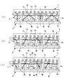
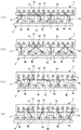
- the center of one core 5a and the center of one permanent magnet 4a coincide with each other in the circumferential direction, and the third core 5a from the core 5a From the state where the center and the center of the fourth permanent magnet 4a from the permanent magnet 4a coincide with each other in the circumferential direction, a rotating magnetic field is generated to rotate leftward in the figure.
- the position of every other armature magnetic pole having the same polarity is made to coincide with the center of each permanent magnet 4a whose center coincides with the core 5a in the circumferential direction.
- the polarity of the magnetic pole is made different from that of the permanent magnet 4a.
- the rotating magnetic field generated by the stator 3 is generated between the first rotor 4 and the second rotor 5 having the core 5 a is disposed between the stator 3 and the first rotor 4.
- Each core 5a is magnetized by the child magnetic pole and the magnet magnetic pole. Since this and the space
- the magnetic lines of force ML connect the armature magnetic pole, the core 5a, and the magnet magnetic pole, whose positions in the circumferential direction coincide with each other, and the armature magnetic pole, the core 5a, and the magnet magnetic pole. It is generated so as to connect the armature magnetic pole, the core 5a, and the magnet magnetic pole adjacent to each other in each circumferential direction.
- the magnetic lines of force ML are linear, no magnetic force that rotates in the circumferential direction acts on the core 5a.
- the magnetic line of force ML is bent, and accordingly, the magnetic line of force ML becomes a straight line.
- Magnetic force acts on the core 5a so as to form a shape.
- the magnetic force line ML protrudes in the direction opposite to the rotating direction of the rotating magnetic field (hereinafter referred to as “magnetic field rotating direction”) in the core 5a. Therefore, the magnetic force acts to drive the core 5a in the magnetic field rotation direction.
- the core 5a is driven in the magnetic field rotation direction by the action of the magnetic force by the magnetic field lines ML, and rotates to the position shown in FIG. 5C, and the second rotor 5 and the second rotating shaft 7 provided with the core 5a. Also rotate in the direction of magnetic field rotation.
- the broken lines in FIGS. 5B and 5C indicate that the magnetic flux amount of the magnetic field lines ML is extremely small and the magnetic connection between the armature magnetic pole, the core 5a, and the magnet magnetic pole is weak. The same applies to other drawings described later.
- the magnetic force line ML bends in the direction opposite to the magnetic field rotating direction in the core 5a ⁇ the core 5a has a linear shape so that the magnetic force line ML becomes linear.
- the operation that the magnetic force acts ⁇ the core 5a, the second rotor 5, and the second rotating shaft 7 rotate in the magnetic field rotating direction is shown in FIGS. 6 (a) to 6 (d), 7 (a) and (a). Repeated as shown in b).
- the electric power supplied to the stator 3 is converted into motive power by the action of the magnetic force due to the magnetic field lines ML as described above, and is output from the second rotating shaft 7.
- FIG. 8 shows a state in which the armature magnetic pole has been rotated by an electrical angle of 2 ⁇ from the state of FIG. 5A.
- FIGS. 9 to 11 the same one armature magnetic pole and permanent magnet 4a are hatched for easy understanding.
- FIG. 9A as in the case of FIG. 5A described above, the center of one core 5a and the center of one permanent magnet 4a coincide with each other in the circumferential direction. From the state where the center of the third core 5a from the core 5a and the center of the fourth permanent magnet 4a from the permanent magnet 4a coincide with each other in the circumferential direction, the rotating magnetic field is moved to the left in the figure. Generate to rotate.
- the position of every other armature magnetic pole having the same polarity is made to coincide with the center of each permanent magnet 4a whose center coincides with the core 5a in the circumferential direction.
- the polarity of the magnetic pole is made different from that of the permanent magnet 4a.
- the magnetic force lines ML connect the armature magnetic pole, the core 5a, and the magnetic magnetic pole whose circumferential positions coincide with each other, and The armature magnetic pole, the core 5a, and the magnet magnetic pole are generated so as to connect the adjacent armature magnetic pole, the core 5a, and the magnet magnetic pole on both sides in the circumferential direction. Further, in this state, since the magnetic lines of force ML are linear, no magnetic force that rotates in the circumferential direction acts on the permanent magnet 4a.
- the permanent magnet 4a is driven in the direction opposite to the magnetic field rotation direction by the action of the magnetic force by the magnetic field lines ML, and rotates to the position shown in FIG. 9C, and the first rotor 4 provided with the permanent magnet 4a and The first rotation shaft 6 also rotates in the direction opposite to the magnetic field rotation direction.
- the rotating magnetic field further rotates, the above-described series of operations, that is, “the magnetic field ML is bent and the permanent magnet 4a is more magnetic than the armature magnetic pole and the extension line of the core 5a connected to each other by the magnetic field line ML.
- the magnetic force acts on the permanent magnet 4a so that the magnetic lines of force ML are linear.
- the permanent magnet 4a, the first rotor 4 and the first rotating shaft 6 are opposite to the magnetic field rotating direction.
- the operation of “rotating to” is repeatedly performed as shown in FIGS. 10 (a) to 10 (d), FIGS. 11 (a) and 11 (b).
- the electric power supplied to the stator 3 is converted into power by the action of the magnetic force generated by the magnetic lines of force ML as described above, and is output from the first rotating shaft 6.
- FIG. 11B shows a state in which the armature magnetic pole has been rotated by an electrical angle of 2 ⁇ from the state of FIG. 9A, which is apparent from a comparison between FIG. 11B and FIG. 9A.
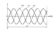
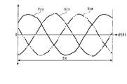
- FIG. 12 shows an example of the transition of the U-phase to W-phase back electromotive voltages Vcu to Vcw while the second rotor electrical angle ⁇ ER2 varies from 0 to 2 ⁇ .
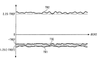
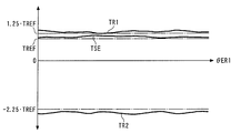
- FIG. 13 shows an example of transition of the driving equivalent torque TSE and the first and second rotor transmission torques TR1 and TR2.
- the number of pole pairs of the armature magnetic pole and the magnet magnetic pole is 8 and 10, respectively, and from the above equation (32), the driving equivalent torque TSE, the first and second rotor transmission torques TR1, TR2
- the driving equivalent torque TSE is approximately ⁇ TREF
- the first rotor transmission torque TR1 is approximately 1.25 ⁇ ( ⁇ TREF)
- the second rotor transmission torque TR2 is approximately 2.25. ⁇ It is TREF.
- This TREF is a predetermined torque value (for example, 200 Nm).
- FIG. 14 shows an example of the transition of the U-phase to W-phase back electromotive voltages Vcu to Vcw while the first rotor electrical angle ⁇ ER1 changes from 0 to 2 ⁇ .
- FIG. 15 shows an example of transition of the driving equivalent torque TSE and the first and second rotor transmission torques TR1 and TR2.
- the driving equivalent torque TSE is approximately TREF
- the first rotor transmission torque TR1 is approximately 1.25 ⁇ TREF
- the second rotor transmission torque TR2 is approximately ⁇ 2.25 ⁇ TREF. It has become.
- the electric motor 1 can be operated only by a single soft magnetic material row constituted by the cores 5a, the electric motor 1 can be reduced in size and manufacturing cost can be reduced. Can do. Further, by setting the ratio of the number of pole pairs of the magnetic poles to the number of pole pairs of the armature poles, the relationship between the magnetic field electrical angular velocity ⁇ MFR, the first and second rotor electrical angular velocities ⁇ ER1, ⁇ ER2, and the drive equivalent torque TSE, The relationship between the first and second rotor transmission torques TR1 and TR2 can be freely set, and therefore the degree of freedom in designing the electric motor 1 can be increased.
- the magnetic field electrical angle position ⁇ MFR is controlled so that the formula (40) is satisfied, an appropriate operation of the electric motor 1 can be ensured.
- the magnetic pole of the permanent magnet 4a since the magnetic pole of the permanent magnet 4a is used, an electric circuit and a coil for supplying electric power to the electromagnet are not required unlike the case of using the magnetic pole of the electromagnet. Thereby, the electric motor 1 can be further reduced in size and the configuration can be simplified. Further, the slip ring for supplying power when the magnetic pole of the electromagnet is used as the magnetic pole becomes unnecessary, and accordingly, the electric motor 1 can be reduced in size and the efficiency can be increased.
- the first and second rotors 4 and 5 are configured to be rotatable.
- one of the both rotors 4 and 5 is configured to be non-rotatable and only the other is rotatable. You may comprise, and you may output motive power from the other.
- one of the first and second rotors 4 and 5 is configured to be non-rotatable, it is obvious from the equation (39) that one of the electrical angular positions of the both rotors 4 and 5 has a value of 0.
- the other electrical angle position of the both 4 and 5 is detected by a sensor or the like, and the rotating magnetic field may be controlled in accordance with the detected other electrical angle position.
- stator 3 rotatably, in that case, an electric motor is used as follows, for example. That is, in a state where power is input to one of the first and second rotors 4, 5 and the stator 3, power is supplied to the stator 3, and this power is converted into power, and the other of the rotors 4, 5 is Output from.
- the formula (41) It is used as a power source for a counter-rotating propeller such that a load torque that satisfies the above conditions acts on the stator 3 and the other simultaneously.
- the rotation angle positions of the specific permanent magnet 4a and the core 5a with respect to the reference coil are detected as the first and second rotor rotation angles ⁇ R1 and ⁇ R2, respectively.
- the rotational angle positions of other parts may be detected.
- the rotation angle position of a specific portion of the fixed portion 4b or the first rotating shaft 6 with respect to a specific portion of the specific V-phase coil 3d, specific W-phase coil 3e, or case 2 is defined as the first rotor rotation angle ⁇ R1.
- the rotation angle position of a specific part of the flange 5b or the second rotation shaft 7 may be detected as the second rotor rotation angle ⁇ R2.
- the magnetic field electrical angle position ⁇ MFR used for controlling the rotating magnetic field is used as the first and second rotor rotation angles ⁇ R1 and ⁇ R2 detected by the first and second rotational position sensors 21 and 22.
- it is used and calculated by the equation (39), it may be obtained by the technique described in Japanese Patent Application No. 2007-280916.
- a planetary gear device in which the ratio of the number of teeth of the sun gear and the ring gear is the same value as the ratio of the other number to the number of one of the armature magnetic pole and the magnet magnetic pole, and a single rotational position sensor are prepared, One of the sun gear and the ring gear is connected to the first rotor 4 and the carrier is connected to the second rotor 5, and the other rotation angle position of the sun gear and the ring gear with respect to the specific U-phase coil 3 c is detected by a rotation position sensor.
- a sun gear is connected to the first rotor 4.
- the rotational angle position detected by the rotational position sensor represents (1 + ⁇ ) ⁇ R2- ⁇ ⁇ ⁇ R1, where the ratio of the number of magnet magnetic poles to the number of armature magnetic poles is ⁇ .
- the rotational magnetic field is controlled by the planetary gear unit and the single rotational position sensor without separately detecting the rotational angular positions of the first and second rotors 4 and 5 by the two sensors. Magnetic field electrical angle position ⁇ MFR used in the above can be obtained.
- the stator 3 and the first rotor 4 are respectively arranged on the outer side and the inner side in the radial direction. On the contrary, they may be arranged on the inner side and the outer side in the radial direction. . Further, the stator 3, the first and second rotors 4, 5 are arranged so as to be aligned in the radial direction, and the electric motor 1 is configured as a so-called radial type, but the stator 3, the first and second rotors 4, 4 are configured. 5 may be arranged so as to be aligned in the axial direction, and the electric motor 1 may be configured as a so-called axial type.
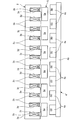
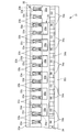
- an electric motor 31 according to a second embodiment of the present invention will be described with reference to FIGS. 16 and 17.
- the electric motor 31 shown in the figure is configured as a linear motor, and is applied to a conveying device.
- the same constituent elements as those in the first embodiment are denoted by the same reference numerals.
- a description will be given focusing on differences from the first embodiment.
- the electric motor 31 includes a stationary case 32, a first stator 33 provided in the case 32, and a first stator provided in the case 32 so as to face the first stator 33. 2 and a mover 35 provided between the stators 33 and 34.
- the case 32 has a plate-like bottom wall 32a whose longitudinal direction is the front-rear direction (depth direction in FIG. 16, vertical direction in FIG. 17), and side walls that extend upward from both ends of the bottom wall 32a and face each other. 32b and 32c are integrated.
- the first stator 33 generates a moving magnetic field, and as shown in FIG. 17, the iron core 33a and the U-phase, V-phase, and W-phase coils 33c, 33d, and 33e provided on the iron core 33a. have.
- the iron core 33a has a rectangular parallelepiped shape in which a plurality of steel plates are stacked, extends in the front-rear direction over the entire case 32, and is attached to the side wall 32b of the case 32.
- a large number of slots 33b are formed on the surface of the iron core 33a on the second stator 34 side, and these slots 33b extend in the vertical direction and are arranged at equal intervals in the front-rear direction.
- the U-phase to W-phase coils 33c to 33e are wound around the slot 33b by distributed winding (wave winding) and connected to the variable power source 15 described above.
- the magnetic poles generated in the iron core 33a are referred to as “armature magnetic poles” as in the first embodiment.
- the armature magnetic poles are represented by (N) and (S) on the iron core 33a and the U-phase to W-phase coils 33c to 33e, as in FIG.
- the number of armature magnetic poles in a predetermined section INT along the front-rear direction is a value 4.
- the second stator 34 has a magnetic pole array composed of a large number of permanent magnets 34a. These permanent magnets 34 a are arranged at equal intervals in the front-rear direction, and this magnetic pole row faces the iron core 33 a of the first stator 33. Each permanent magnet 34a is formed in a rectangular parallelepiped shape, and its vertical length is set to be the same as that of the iron core 33a. In addition, the permanent magnet 34a is attached to the right end portion of the upper surface of the bottom wall 32a (the right side in FIG. 16 is “right”) via the fixing portion 34b and is attached to the side wall 32c.
- the fixed portion 34b is made of a soft magnetic material such as iron.
- each permanent magnet 34a Since the permanent magnet 34a is attached to the fixed portion 34b made of iron in this way, each permanent magnet 34a has one magnetic pole (N) or (S) at the end on the first stator 33 side. Appears. 17 and 18, the magnetic poles of the permanent magnet 34a (hereinafter referred to as “magnet magnetic poles” as in the first embodiment) are denoted by (N) and (S), as in FIG. Further, as shown in FIG. 18, the polarities of the two permanent magnets 34a adjacent to each other in the front-rear direction are different from each other, and the number of permanent magnets 34a in the predetermined section INT is 8.
- the mover 35 has a soft magnetic body row composed of a top plate 35a provided above the first and second stators 33, 34 and six cores 35b provided on the top plate 35a. .
- the size of the top plate 35a in the front-rear direction and the left-right direction is smaller than that of the case 32 and covers a part of the first and second stators 33 and 34.
- Each core 35b is a soft magnetic material, for example, a rectangular parallelepiped shape in which a plurality of steel plates are laminated, and the length in the vertical direction is set to be the same as that of the iron core 33a. Moreover, the six cores 35b are connected by the top plate 35a via the connection part 35c provided in each upper end part, and are located in a line at equal intervals in the front-back direction. Further, the soft magnetic material row composed of the cores 35b is disposed between the iron core 33a of the first stator 33 and the magnetic pole row of the second stator 34 with a predetermined distance therebetween. A wheel 35d is provided at the bottom of each core 35b.
- the core 35b is placed on a rail (not shown) on the upper surface of the bottom wall 32a via the wheel 35d, whereby the mover 35 including the core 35b is movable in the front-rear direction. It cannot move left and right.
- the connecting portion 35c is omitted for convenience.
- the second stator 34 corresponds to the first structure in the present invention
- the permanent magnet 34a corresponds to the magnetic pole in the present invention
- the first stator 33 corresponds to the second structure in the present invention
- the iron core 33a and the U-phase to W-phase coils 33c to 33e correspond to the armature in the present invention
- the mover 35 corresponds to the third structure in the present invention
- the core 35b corresponds to the soft magnetic body in the present invention.
- the electric motor 31 is provided with an optical position sensor 41 (relative positional relationship detecting means), and this position sensor 41 is a specific mover 35 for a specific U-phase coil 33c of the first stator 33.
- a detection signal indicating the position of the core 35 b (hereinafter referred to as “mover position”) is output to the ECU 16.
- the ECU 16 obtains the relative positional relationship between the movable element 35 and the first and second stators 33 and 34 according to the detected movable element position, and based on this positional relationship, the U phase to the W phase.
- the energization to the coils 33c to 33e is controlled, thereby controlling the moving magnetic field. More specifically, this control is performed as follows.
- the predetermined section INT there are four armature magnetic poles, eight magnet magnetic poles, and six cores 35b. That is, the ratio of the number of armature magnetic poles, the number of magnet magnetic poles, and the number of cores 35b is set to 1: 2: (1 + 2) / 2.
- This ⁇ EM is a value obtained by converting the mover position into an electrical angle position (hereinafter referred to as “mover electrical angle position”). Specifically, the detected mover position has the number of pole pairs of the armature magnetic poles, that is, the value. It is a value obtained by multiplying two. Note that this control is performed by controlling the current flowing through the U-phase to W-phase coils 33c to 33e by vector control, as in the first embodiment.
- This ⁇ EM is a time differential value of the mover electrical angular position ⁇ EM, and is a value obtained by converting the moving speed of the mover 35 into an electrical angular speed (hereinafter referred to as “mover electrical angular speed”).
- the driving equivalent thrust FSE the driving equivalent thrust FSE
- this driving equivalent thrust FSE and the thrust transmitted to the mover 35 (hereinafter “movable”).
- the electric motor 31 can be operated only by a single soft magnetic material row composed of the six cores 35b. In addition, the manufacturing cost can be reduced. Further, by setting the ratio of the number of pole pairs of the magnetic poles to the number of pole pairs of the armature poles in the predetermined section INT, the relationship between the magnetic field electrical angular velocity ⁇ MFM and the mover electrical angular velocity ⁇ EM, the driving equivalent thrust FSE, and the mover transmission The relationship of the thrust FM can be set freely, and therefore the degree of freedom in designing the electric motor 31 can be increased.
- the magnetic pole of the permanent magnet 34a is used similarly to 1st Embodiment, the further size reduction of the electric motor 31 and simplification of a structure can be achieved.
- the second mover is configured by connecting a plurality of permanent magnets 34 a of the second stator 34 with a top plate different from the top plate 35 a, and the second mover is moved in the front-rear direction with respect to the case 32. It can be moved freely. And like 1st Embodiment, you may make it output motive power from at least one of the needle
- the third mover may be configured by attaching the iron core 33a of the first stator 33 to the top plate, and the third mover may be configured to be movable in the front-rear direction with respect to the case 32. . As described in the first embodiment, power may be output from the mover 35, the second mover, or the third mover.
- the position of the specific permanent magnet 34a of the second mover with respect to the specific U-phase coil 33c is detected by a sensor or the like in addition to the position of the mover 35.
- the magnetic field electrical angle position ⁇ MFM is calculated based on the equation (39) according to the mover position and the detected position of the second mover.
- the calculated magnetic field electrical angle position ⁇ MFM is used for controlling the rotating magnetic field.
- the position of the specific core 35a with respect to the specific U-phase coil 33c is detected as the mover position.
- the position of the part may be detected.
- the position of a specific part such as the top plate 35a with respect to a specific part of the specific V-phase coil 33d, the specific W-phase coil 33e, or the case 32 may be detected as the mover position.
- one magnetic pole is constituted by the magnetic poles of a single permanent magnet 4a, 34a, but may be constituted by magnetic poles of a plurality of permanent magnets.
- these two permanent magnets are arranged in an inverted V shape so that the magnetic poles of the two permanent magnets approach each other on the side of the stator 3 (first stator 33), magnetic field lines are formed. ML directivity can be increased.
- an electromagnet or an armature capable of generating a moving magnetic field may be used instead of the permanent magnets 4a and 34a in the embodiment.
- the U-phase to W-phase coils 3c to 3e and 33c to 33e are wound around the slots 3b and 33b by distributed winding, but the present invention is not limited to this, and concentrated winding may be used.
- the coils 3c to 3e and 33c to 33e are constituted by U-phase to W-phase three-phase coils. However, if a moving magnetic field (rotating magnetic field) can be generated, the number of phases of this coil is equal to this. It is not limited and is arbitrary.
- slots 3b and 33b it is needless to say that any number other than that shown in the embodiment may be adopted.
- the slots 3b and 33b, the permanent magnets 4a and 34a, and the cores 5b and 35b are arranged at equal intervals, but may be arranged at unequal intervals.
- the first rotational position sensor 21, the second rotational position sensor 22, and the position sensor 41 are electromagnetic induction types, but may be optical types.
- the ECU 16 is used as the control means in the present invention, but a combination of a microcomputer and an electric circuit may be used. In addition, it is possible to appropriately change the detailed configuration within the scope of the gist of the present invention.
- the electric motor of the present invention can be reduced in size and manufacturing cost, and is extremely useful for increasing the degree of freedom in design.
Landscapes
- Engineering & Computer Science (AREA)
- Power Engineering (AREA)
- Physics & Mathematics (AREA)
- Chemical & Material Sciences (AREA)
- Combustion & Propulsion (AREA)
- Electromagnetism (AREA)
- Permanent Magnet Type Synchronous Machine (AREA)
- Linear Motors (AREA)
- Control Of Linear Motors (AREA)
Priority Applications (7)
| Application Number | Priority Date | Filing Date | Title |
|---|---|---|---|
| US12/920,689 US8169116B2 (en) | 2008-04-14 | 2009-02-18 | Electric motor |
| RU2010146130/07A RU2454774C9 (ru) | 2008-04-14 | 2009-02-18 | Электродвигатель |
| CN200980112913XA CN101999203B (zh) | 2008-04-14 | 2009-02-18 | 电动机 |
| CA2720974A CA2720974C (en) | 2008-04-14 | 2009-02-18 | Electric motor |
| EP20090733208 EP2273657B1 (en) | 2008-04-14 | 2009-02-18 | Electric motor |
| BRPI0911654A BRPI0911654A2 (pt) | 2008-04-14 | 2009-02-18 | motor elétrico |
| ES09733208T ES2385286T3 (es) | 2008-04-14 | 2009-02-18 | Motor eléctrico |
Applications Claiming Priority (2)
| Application Number | Priority Date | Filing Date | Title |
|---|---|---|---|
| JP2008105058A JP4747184B2 (ja) | 2008-04-14 | 2008-04-14 | 電動機 |
| JP2008-105058 | 2008-04-14 |
Publications (1)
| Publication Number | Publication Date |
|---|---|
| WO2009128287A1 true WO2009128287A1 (ja) | 2009-10-22 |
Family
ID=41198988
Family Applications (1)
| Application Number | Title | Priority Date | Filing Date |
|---|---|---|---|
| PCT/JP2009/052780 WO2009128287A1 (ja) | 2008-04-14 | 2009-02-18 | 電動機 |
Country Status (11)
| Country | Link |
|---|---|
| US (1) | US8169116B2 (pt) |
| EP (1) | EP2273657B1 (pt) |
| JP (1) | JP4747184B2 (pt) |
| CN (1) | CN101999203B (pt) |
| BR (1) | BRPI0911654A2 (pt) |
| CA (1) | CA2720974C (pt) |
| ES (1) | ES2385286T3 (pt) |
| MY (1) | MY154172A (pt) |
| RU (1) | RU2454774C9 (pt) |
| TW (1) | TWI385898B (pt) |
| WO (1) | WO2009128287A1 (pt) |
Cited By (8)
| Publication number | Priority date | Publication date | Assignee | Title |
|---|---|---|---|---|
| WO2011013589A1 (ja) * | 2009-07-29 | 2011-02-03 | 本田技研工業株式会社 | 動力装置 |
| WO2011036938A1 (ja) * | 2009-09-25 | 2011-03-31 | 本田技研工業株式会社 | 移動装置 |
| JP2011079408A (ja) * | 2009-10-06 | 2011-04-21 | Honda Motor Co Ltd | 動力システム |
| WO2011045963A1 (ja) * | 2009-10-13 | 2011-04-21 | 本田技研工業株式会社 | 動力装置 |
| JP2011084117A (ja) * | 2009-10-13 | 2011-04-28 | Honda Motor Co Ltd | ハイブリッド車両 |
| JP2011130661A (ja) * | 2009-12-18 | 2011-06-30 | General Electric Co <Ge> | 二重反転可能発電機 |
| US8375695B2 (en) | 2009-06-30 | 2013-02-19 | General Electric Company | Aircraft gas turbine engine counter-rotatable generator |
| TWI703793B (zh) * | 2018-06-18 | 2020-09-01 | 日商三菱電機股份有限公司 | 線性馬達的定子、線性馬達及線性馬達系統 |
Families Citing this family (24)
| Publication number | Priority date | Publication date | Assignee | Title |
|---|---|---|---|---|
| JP4759589B2 (ja) * | 2008-04-24 | 2011-08-31 | 本田技研工業株式会社 | 動力装置 |
| JP4505524B2 (ja) * | 2008-07-22 | 2010-07-21 | 本田技研工業株式会社 | 動力装置 |
| JP5421709B2 (ja) * | 2009-09-30 | 2014-02-19 | Thk株式会社 | リニアモータの駆動システム及び制御方法 |
| US20120194108A1 (en) * | 2009-10-06 | 2012-08-02 | Honda Motor Co., Ltd. | Motor system |
| JP5354687B2 (ja) | 2010-09-29 | 2013-11-27 | 山洋電気株式会社 | 移動磁場発生装置 |
| JP5511713B2 (ja) * | 2011-02-28 | 2014-06-04 | 三菱電機株式会社 | リニアモータ |
| EP2578438B1 (en) * | 2012-01-10 | 2017-04-26 | Volvo Car Corporation | Dual shaft motor |
| JP5621794B2 (ja) * | 2012-01-30 | 2014-11-12 | 株式会社デンソー | 磁気変調式複軸モータ |
| JP5964633B2 (ja) * | 2012-03-29 | 2016-08-03 | 山洋電気株式会社 | 筒形リニアモータ |
| TWI455448B (zh) * | 2012-05-16 | 2014-10-01 | Ting Hung Su | High torque planetary magnetic motors |
| US11353084B2 (en) * | 2013-03-15 | 2022-06-07 | Clearmotion Acquisition I Llc | Rotary actuator driven vibration isolation |
| US9431884B2 (en) * | 2013-03-26 | 2016-08-30 | Caterpillar Inc. | Dual rotor switched reluctance machine |
| JP5842852B2 (ja) * | 2013-04-02 | 2016-01-13 | トヨタ自動車株式会社 | 回転電機制御システム及び回転電機の制御方法 |
| AT514240B1 (de) * | 2013-04-22 | 2015-02-15 | Hitzinger Gmbh | Energiespeicher und Vorrichtung zur unterbrechungsfreien Energieversorgung |
| GB201308270D0 (en) * | 2013-05-08 | 2013-06-12 | Magnomatics Ltd | Methods and apparatus for rotor position estimation |
| JP5695711B2 (ja) * | 2013-08-22 | 2015-04-08 | 山洋電気株式会社 | 回転型モータ |
| CN104201859B (zh) * | 2014-08-28 | 2016-08-17 | 浙江大学 | 一种不对称双边型混合励磁直线同步电动机 |
| US10840791B2 (en) * | 2015-04-21 | 2020-11-17 | Mitsubishi Electric Corporation | Linear motor |
| TR201807226T4 (tr) * | 2015-10-01 | 2018-06-21 | Tetra Laval Holdings & Finance | Elektromanyetik enerji transferine sahip tahrik sistemi. |
| GB201520131D0 (en) | 2015-11-16 | 2015-12-30 | Rolls Royce Plc | Variable gear ratio electrical machine |
| CN106655673B (zh) * | 2016-11-18 | 2019-02-01 | 东南大学 | 一种定子分离式直线旋转两自由度永磁作动器 |
| EP3700068A1 (de) * | 2019-02-22 | 2020-08-26 | Siemens Aktiengesellschaft | Elektrische maschine |
| US10897166B1 (en) * | 2019-12-19 | 2021-01-19 | Michael Hanagan | Method and apparatus to control an armature rotating within a magnetic circuit |
| CN114123697B (zh) * | 2021-11-04 | 2022-08-26 | 新亚东方电能科技有限公司 | 新能源发电机转子双驱动装置 |
Citations (5)
| Publication number | Priority date | Publication date | Assignee | Title |
|---|---|---|---|---|
| JP2006288012A (ja) * | 2005-03-31 | 2006-10-19 | Fujitsu General Ltd | アキシャルギャップ型電動機 |
| JP2007280916A (ja) | 2006-03-17 | 2007-10-25 | Taiyo Yuden Co Ltd | ランプ点灯装置 |
| JP2008017543A (ja) * | 2006-07-03 | 2008-01-24 | Daikin Ind Ltd | モータの着磁方法 |
| JP2008043138A (ja) * | 2006-08-09 | 2008-02-21 | Honda Motor Co Ltd | 補機駆動装置 |
| JP2008067592A (ja) | 2006-08-09 | 2008-03-21 | Honda Motor Co Ltd | 電動機 |
Family Cites Families (13)
| Publication number | Priority date | Publication date | Assignee | Title |
|---|---|---|---|---|
| RU2025870C1 (ru) * | 1991-07-31 | 1994-12-30 | Владик Завенович Туманян | Электрический двигатель |
| BR9804426A (pt) * | 1998-10-16 | 2000-05-16 | Elevadores Atlas S A | Máquina elétrica de relutância subsìncrona. |
| JP2000350309A (ja) * | 1999-06-04 | 2000-12-15 | Denso Corp | 動力変換装置ならびに車両用駆動装置 |
| JP3951524B2 (ja) * | 1999-11-24 | 2007-08-01 | 株式会社デンソー | ハイブリッド車用回転電機装置 |
| JP4269544B2 (ja) * | 2000-09-14 | 2009-05-27 | 株式会社デンソー | 複数ロータ型同期機 |
| JP3531622B2 (ja) * | 2001-04-18 | 2004-05-31 | トヨタ自動車株式会社 | 動力出力装置 |
| RU2280940C1 (ru) * | 2005-03-22 | 2006-07-27 | Владимир Георгиевич Комаров | Электромеханический силовой агрегат |
| KR100631572B1 (ko) * | 2005-06-16 | 2006-10-09 | 엘지전자 주식회사 | 역회전 방지장치를 구비한 전동기 |
| JP4539528B2 (ja) * | 2005-10-20 | 2010-09-08 | 株式会社豊田中央研究所 | 回転電機及びそれを備えるハイブリッド駆動装置 |
| RU2313885C2 (ru) * | 2005-12-21 | 2007-12-27 | Алексей Владимирович Булычев | Электрическая машина (варианты) |
| CN101322303B (zh) * | 2006-04-20 | 2010-12-29 | 松下电器产业株式会社 | 电机 |
| RU2321140C1 (ru) * | 2006-11-02 | 2008-03-27 | Казанский государственный технический университет им. А.Н. Туполева | Синхронный электродвигатель |
| JP4505524B2 (ja) * | 2008-07-22 | 2010-07-21 | 本田技研工業株式会社 | 動力装置 |
-
2008
- 2008-04-14 JP JP2008105058A patent/JP4747184B2/ja active Active
-
2009
- 2009-02-18 RU RU2010146130/07A patent/RU2454774C9/ru not_active IP Right Cessation
- 2009-02-18 BR BRPI0911654A patent/BRPI0911654A2/pt not_active IP Right Cessation
- 2009-02-18 CA CA2720974A patent/CA2720974C/en not_active Expired - Fee Related
- 2009-02-18 MY MYPI2010004790A patent/MY154172A/en unknown
- 2009-02-18 WO PCT/JP2009/052780 patent/WO2009128287A1/ja active Application Filing
- 2009-02-18 ES ES09733208T patent/ES2385286T3/es active Active
- 2009-02-18 EP EP20090733208 patent/EP2273657B1/en active Active
- 2009-02-18 CN CN200980112913XA patent/CN101999203B/zh active Active
- 2009-02-18 US US12/920,689 patent/US8169116B2/en active Active
- 2009-04-08 TW TW98111714A patent/TWI385898B/zh not_active IP Right Cessation
Patent Citations (5)
| Publication number | Priority date | Publication date | Assignee | Title |
|---|---|---|---|---|
| JP2006288012A (ja) * | 2005-03-31 | 2006-10-19 | Fujitsu General Ltd | アキシャルギャップ型電動機 |
| JP2007280916A (ja) | 2006-03-17 | 2007-10-25 | Taiyo Yuden Co Ltd | ランプ点灯装置 |
| JP2008017543A (ja) * | 2006-07-03 | 2008-01-24 | Daikin Ind Ltd | モータの着磁方法 |
| JP2008043138A (ja) * | 2006-08-09 | 2008-02-21 | Honda Motor Co Ltd | 補機駆動装置 |
| JP2008067592A (ja) | 2006-08-09 | 2008-03-21 | Honda Motor Co Ltd | 電動機 |
Non-Patent Citations (1)
| Title |
|---|
| See also references of EP2273657A4 |
Cited By (12)
| Publication number | Priority date | Publication date | Assignee | Title |
|---|---|---|---|---|
| US8375695B2 (en) | 2009-06-30 | 2013-02-19 | General Electric Company | Aircraft gas turbine engine counter-rotatable generator |
| WO2011013589A1 (ja) * | 2009-07-29 | 2011-02-03 | 本田技研工業株式会社 | 動力装置 |
| WO2011036938A1 (ja) * | 2009-09-25 | 2011-03-31 | 本田技研工業株式会社 | 移動装置 |
| US8647230B2 (en) | 2009-09-25 | 2014-02-11 | Honda Motor Co., Ltd. | Moving apparatus |
| JP2011079408A (ja) * | 2009-10-06 | 2011-04-21 | Honda Motor Co Ltd | 動力システム |
| WO2011045963A1 (ja) * | 2009-10-13 | 2011-04-21 | 本田技研工業株式会社 | 動力装置 |
| JP2011084117A (ja) * | 2009-10-13 | 2011-04-28 | Honda Motor Co Ltd | ハイブリッド車両 |
| JP5256351B2 (ja) * | 2009-10-13 | 2013-08-07 | 本田技研工業株式会社 | 動力装置 |
| US8564146B2 (en) | 2009-10-13 | 2013-10-22 | Honda Motor Co., Ltd. | Power plant |
| JP2011130661A (ja) * | 2009-12-18 | 2011-06-30 | General Electric Co <Ge> | 二重反転可能発電機 |
| EP2337192A3 (en) * | 2009-12-18 | 2012-06-06 | General Electric Company | Counter-rotatable generator |
| TWI703793B (zh) * | 2018-06-18 | 2020-09-01 | 日商三菱電機股份有限公司 | 線性馬達的定子、線性馬達及線性馬達系統 |
Also Published As
| Publication number | Publication date |
|---|---|
| CN101999203A (zh) | 2011-03-30 |
| CA2720974A1 (en) | 2009-10-22 |
| MY154172A (en) | 2015-05-15 |
| EP2273657B1 (en) | 2012-05-23 |
| ES2385286T3 (es) | 2012-07-20 |
| JP4747184B2 (ja) | 2011-08-17 |
| EP2273657A4 (en) | 2011-04-20 |
| RU2454774C1 (ru) | 2012-06-27 |
| CA2720974C (en) | 2012-07-10 |
| BRPI0911654A2 (pt) | 2015-10-13 |
| RU2454774C9 (ru) | 2012-12-27 |
| TWI385898B (zh) | 2013-02-11 |
| JP2009261071A (ja) | 2009-11-05 |
| US20110001364A1 (en) | 2011-01-06 |
| EP2273657A1 (en) | 2011-01-12 |
| US8169116B2 (en) | 2012-05-01 |
| CN101999203B (zh) | 2013-03-06 |
| TW201006097A (en) | 2010-02-01 |
Similar Documents
| Publication | Publication Date | Title |
|---|---|---|
| JP4747184B2 (ja) | 電動機 | |
| JP4576406B2 (ja) | 電動機 | |
| JP4654289B2 (ja) | 補機駆動装置 | |
| US8232701B2 (en) | Magnetic machine | |
| WO2018054282A1 (zh) | 低振动转矩的永磁无刷直流电动机系统 | |
| JP4902494B2 (ja) | 回転角度位置検出装置 | |
| JP5708566B2 (ja) | 電磁カップリング | |
| JP5171782B2 (ja) | 動力システム | |
| JP2777714B2 (ja) | ブラシレスモータの制御装置 | |
| JP2008141908A (ja) | ブラシレスモータおよびそれを備えた電動パワーステアリング装置 | |
| JP5306958B2 (ja) | 電動機システム | |
| JP5362513B2 (ja) | 動力システム | |
| WO2021079577A1 (ja) | モータとその制御装置 | |
| JP5139820B2 (ja) | リニアモータ | |
| JP2013198325A (ja) | 電動機 | |
| JP5105428B2 (ja) | 電動機及び電動機の制御装置 | |
| JP2013198326A (ja) | 電動機及びその制御装置 |
Legal Events
| Date | Code | Title | Description |
|---|---|---|---|
| WWE | Wipo information: entry into national phase |
Ref document number: 200980112913.X Country of ref document: CN |
|
| 121 | Ep: the epo has been informed by wipo that ep was designated in this application |
Ref document number: 09733208 Country of ref document: EP Kind code of ref document: A1 |
|
| WWE | Wipo information: entry into national phase |
Ref document number: 12920689 Country of ref document: US |
|
| WWE | Wipo information: entry into national phase |
Ref document number: 2720974 Country of ref document: CA |
|
| WWE | Wipo information: entry into national phase |
Ref document number: 6545/CHENP/2010 Country of ref document: IN |
|
| WWE | Wipo information: entry into national phase |
Ref document number: 2009733208 Country of ref document: EP |
|
| NENP | Non-entry into the national phase |
Ref country code: DE |
|
| WWE | Wipo information: entry into national phase |
Ref document number: 2010146130 Country of ref document: RU |
|
| ENP | Entry into the national phase |
Ref document number: PI0911654 Country of ref document: BR Kind code of ref document: A2 Effective date: 20101011 |