WO2009119035A1 - コンバインの脱穀装置 - Google Patents
コンバインの脱穀装置 Download PDFInfo
- Publication number
- WO2009119035A1 WO2009119035A1 PCT/JP2009/001164 JP2009001164W WO2009119035A1 WO 2009119035 A1 WO2009119035 A1 WO 2009119035A1 JP 2009001164 W JP2009001164 W JP 2009001164W WO 2009119035 A1 WO2009119035 A1 WO 2009119035A1
- Authority
- WO
- WIPO (PCT)
- Prior art keywords
- teeth
- handling
- spiral
- combine
- threshing
- Prior art date
- Legal status (The legal status is an assumption and is not a legal conclusion. Google has not performed a legal analysis and makes no representation as to the accuracy of the status listed.)
- Ceased
Links
Images


Classifications
-
- A—HUMAN NECESSITIES
- A01—AGRICULTURE; FORESTRY; ANIMAL HUSBANDRY; HUNTING; TRAPPING; FISHING
- A01F—PROCESSING OF HARVESTED PRODUCE; HAY OR STRAW PRESSES; DEVICES FOR STORING AGRICULTURAL OR HORTICULTURAL PRODUCE
- A01F12/00—Parts or details of threshing apparatus
- A01F12/18—Threshing devices
- A01F12/22—Threshing cylinders with teeth
Definitions
- the present invention relates to a threshing device included in a combine, and more particularly, to a tooth handling of a barrel that the threshing device has.
- Patent Document 1 discloses such a handling cylinder.
- the handling cylinder of this Patent Document 1 divides a plurality of teeth to be implanted on the circumferential surface of the handling cylinder on a screw-like line so as to give a transfer action to the cereal from the supply side to the discharge side,
- the tooth handling from the starting end side portion to the terminal end side portion of the handling cylinder is configured such that a transfer angle is variable and is arranged in a straight line in the same direction as the axial direction of the handling cylinder.
- Japanese Patent No. 2578075 Japanese Patent No. 2578075
- patent document 1 can adjust the action of the threshing process according to the condition of the threshing object by changing the transfer angle of the tooth handling, this avoids the momentary increase in load due to the simultaneous action of the tooth handling described above. I can't.
- all of the harvested cereal straws are input to the threshing apparatus, so that the influence of the load caused by the threshing process is increased.
- threshing objects are easily entangled with each other during transportation, such as soybeans, and are discharged outside the combine machine without threshing properly, There was a possibility that the threshing object in the form of a rope would be clogged in the threshing device or the waste transporting device.
- the present invention has been made in view of the above circumstances, and its purpose is to prevent tooth handling from colliding with an object to be threshed at the same time, and to properly handle teeth even in threshing that tends to become rope-like.
- An object of the present invention is to provide a combine threshing device capable of acting on the slush.
- a threshing device for a full-volume combine combine that threshs cereal with a handling cylinder having a plurality of teeth on the peripheral surface. That is, the teeth are arranged along a first helix that matches the axis of the handle cylinder. Further, the tooth-handling and the tooth-handling adjacent to the tooth-handling in the axial direction of the barrel are arranged so as to have different phases and partially overlap when viewed in the axial direction.
- a series of tooth handling teeth in which adjacent teeth are partially overlapped with each other in the axial direction of the handle cylinder is a second axis which is coaxial with the first spiral and has the same winding direction and a larger pitch than the first spiral. Arranged along a spiral.
- this threshing device includes a chaff sheave and a cutting blade.
- a plurality of chaff sheaves are arranged below the handling cylinder in order to select the grains falling from the handling cylinder.
- the cutting blade includes at least a position from the vicinity of the teeth disposed on the most upstream side in the handling cylinder to a position corresponding to a downstream end portion of the chaff sheave disposed on the most upstream side among the chaff sheaves. Placed in.
- the said cutting blade is arrange
- the cutting blade acts on the threshing object, the threshing work can be performed more effectively in combination with the continuous action of the tooth handling. Moreover, since a cutting blade is arrange
- an angle-adjustable dust feeding valve disposed in the vicinity of the handling cylinder.
- the peripheral surface of the treatment drum is configured by connecting a plurality of plate-like members curved in an arc shape, and a part of the plurality of teeth-handling is the plate-like shape. It is preferable to arrange so as to straddle the joints of the members.
- the peripheral surface of the handling cylinder can be configured by joining the divided plate-like members, the manufacture of the handling cylinder becomes easy.
- the tooth handling is arrange
- the side view which showed the mode of the combine of this embodiment The side view which showed the mode of the principal part of the threshing apparatus.
- the enlarged front view of a threshing apparatus The side view and expanded view which showed the plate-shaped member which comprises the surrounding surface of a handling cylinder.
- the principal part top view of a threshing apparatus The expanded sectional view which showed the treatment cylinder and tooth treatment of the modification.
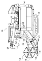
- FIG. 1 is a side view of a combine according to an embodiment of the present invention.
- “left side”, “right side”, and the like simply mean the left side and the right side in the direction in which the combine moves forward.
- a full-volume combine combine 10 is provided with a cutting unit 12 for cutting soybean, rice, wheat and other stock sources at the front of the machine body, and a crawler unit 11 as an advancing unit. It is configured for the lower part of the fuselage.
- a threshing device 14 for threshing the harvested culm is provided on the upper left side of the combine 10.
- a Glen tank 15 is provided on the upper right side of the combine 10 so as to be juxtaposed with the threshing device 14.
- An operation unit 17 for operating the combine 10 is disposed in front of the Glen tank 15.
- the driving unit 17 is provided with a driving operation unit 52 and a driving seat. By operating the driving operation unit 52, various operations of the combine 10 such as cutting and traveling are performed.
- An unillustrated engine as a drive source for the combine 10 is disposed below the operation unit 17.
- the left and right crawler portions 11 are controlled by a traveling mission device (not shown), so that the traveling direction and speed of the combine 10 can be adjusted.
- the mowing unit 12 includes a divider 18 disposed at the front for separating a crop to be harvested and a crop not to be harvested, a cutting blade unit 13 disposed at the rear of the divider 18, and a reel unit disposed above the divider 18. 16.
- the divider 18 is formed in a substantially pyramid shape, and is arranged on both the left and right sides of the body of the combine 10 so that the tip portion protrudes in front of the combine.
- the cutting blade part 13 is provided with the cutting blade and the receiving blade, and cuts the stock of a crop by driving both to the left and right.
- the reel portion 16 is formed in a substantially hexagonal column shape by a frame member, and is provided horizontally in the body width direction of the combine 10.
- the reel portion 16 is rotatably supported and a plurality of unillustrated reel tines are arranged side by side on the frame member. With this configuration, when the reel unit 16 is rotationally driven, the crop harvested by the cutting blade unit 13 can be taken in by the reel tine and the frame member, and can be sent to the transport unit 21 described later.
- the conveyance unit 21 includes a screw conveyor 46 that is arranged with its axis line directed in the left-right direction of the combine 10, and a feeder house 47 that is arranged in front of the threshing device 14.
- the screw conveyor 46 conveys the culm from the right side to the left side of the combine (from the back side to the front side in FIG. 1) and feeds it into the feeder house 47.
- the feeder house 47 includes a chain conveyor 48 inside, and the cereal straw is conveyed to the threshing device 14 by the chain conveyor 48.
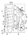
- FIG. 2 is a side view showing the main part of the threshing device 14.
- FIG. 3 is an enlarged front view of the threshing apparatus 14 showing the handling barrel 30 and the surroundings.
- the threshing apparatus 14 includes a handling cylinder 30 for threshing and threshing, and the handling cylinder 30 is arranged over substantially the entire longitudinal direction in the threshing apparatus 14.
- the handling cylinder 30 is configured in a cylindrical shape with a chamfered tip, and a spiral impeller 54 for taking in the culm is provided at the tip.
- a plurality of teeth 41 are implanted on the peripheral surface of the barrel 30 on the downstream side of the impeller 54.
- the teeth 41 are arranged according to a predetermined rule, details of which will be described later.
- a cone cave 34 is provided at a position below the handling cylinder 30.
- the cone cave 34 is formed in a circular arc shape so as to cover the lower portion of the handling cylinder 30.
- the cereals conveyed from the feeder house 47 to the threshing device 14 are shed by the impact action caused by the rotation of the handling drum 30, the ironing action caused by the tooth handling 41, and the kneading action caused by the corn cave.
- the threshing device 14 includes an oscillating sorting device 32 that is laterally arranged below the handling cylinder 30, and a tang fan 38 is further provided below the oscillating sorting device 32.
- the swing sorting device 32 and the red pepper fan 38 constitute a sorting device in the threshing device 14.
- the rocking sorter 32 will be described.
- the swing sorting device 32 includes a first chaff sheave 36 and a second chaff sheave 37 in order from upstream to downstream in the grain conveyance direction.
- the first chaff sheave 36 and the second chaff sheave 37 are for performing rough sorting of grains and swarf, and include a plurality of chaff fins that are horizontally mounted in the width direction of the swing sorting device 32.
- the angle of the chaff fin is configured to be changeable, and the amount of grain leakage can be adjusted by adjusting the angle.
- the tang fan 38 is installed in the width direction of the swing sorting device 32.
- the first conveyor rod 26 and the second conveyor rod 27 are provided laterally at a position downstream of the tang fan 38.
- the first conveyor rod 26 is disposed below the first chaff sheave 36 so as to be able to collect the first item.
- the sorting wind generated by the Kara fan 38 is applied to the threshing object falling from the swing sorting device 32. Then, a heavy object having a specific gravity falling almost vertically regardless of the sorting wind is sent to the first conveyor bowl 26, and a lighter specific gravity article is sent to the second conveyor bowl 27 as a second article.
- the processed product after threshing can be selected by specific gravity.
- the strength of the sorting wind and the like are adjusted so that an item having a slightly lower specific gravity falls on the second conveyor rod 27. Due to the interaction between the swing sorting device 32 and the wind sorting device, the processed product after threshing is transported from the front side to the back side of the machine body to which the cereal straw is transported. Selected.
- the downstream end of the first conveyor 23 in the transport direction protrudes from the wall on the right side (the back side of the paper in FIG. 2) of the threshing device 14, and the threshing cylinder arranged in the vertical direction on this protruding portion. 19 is connected.
- the first thing that has been sorted by the sorting device and dropped onto the first conveyor bowl 26 is conveyed to the Glen tank 15 through the first conveyor 23 and the cereal cylinder 19.
- the downstream end of the second conveyor 24 in the transport direction protrudes from the wall on the right side (the back side in FIG. 2) of the threshing device 14, and the reduction cylinder 20 is connected to the protruding portion.
- the reduction cylinder 20 is disposed so as to extend toward the lower portion of the upstream portion of the handling cylinder 30, and a second processing device 44 that processes the second product and discharges it to the swing sorting device 32 at the tip thereof. Is connected.
- the second item dropped on the second conveyor cage 27 is conveyed by the second conveyor 24 from the front side to the back side in FIG. Then, the second product is conveyed from the terminal end of the second conveyor 24 to the second processing device 44 through the reduction cylinder 20 and is returned to the swing sorting device 32 after appropriate processing.
- the grain threshed from the culm harvested by the combine 10 is sorted into the first and second by the sorting device. Then, the sorted first item is accumulated in the Glen tank 15 via the first conveyor 23 and the whipping cylinder 19. The first thing stored in the Glen tank 15 is discharged out of the machine via a discharge auger 51 shown in FIG. On the other hand, the second product is returned to the swing sorting device 32 via the second conveyor 24, the reducing cylinder 20, and the second processing device 44, and sorted again.
- each tooth-treating tooth 41 is disposed on the intersection of two types of spirals 81 and 82 indicated by chain lines in FIG.
- the two types of spirals 81 and 82 both have the same axis as the rotation axis of the handling cylinder 30 and have the same winding direction but different pitches.
- the spiral 81 having the smaller pitch is referred to as a first spiral
- the spiral 82 having the larger pitch is referred to as a second spiral.
- the first spiral 81 circulates around the peripheral surface of the handling cylinder 30 a plurality of times, and intersects the second spiral 82 in the path.
- the teeth 41 are arranged along the first spiral 81 at equal intervals.
- the tooth handling 41 arranged at the beginning of the first turn of the first spiral 81 and the tooth handling 41 arranged at the beginning of the second turn are adjacent to each other in the axial direction of the handling cylinder 30.
- Adjacent teeth 41 are not arranged on a straight line parallel to the axis of the cylinder 30, but are slightly shifted in the circumferential direction of the cylinder 30 (that is, slightly different in phase). Due to this displacement, the adjacent teeth 41 are arranged so as to partially overlap each other when viewed in the axial direction of the barrel 30. Then, the above-described deviation is repeated every time the first spiral 81 makes one round, so that a series of teeth 41 adjacent to each other in the axial direction of the cylinder 30 are arranged along the second spiral 82.
- the second spiral 82 Since the second spiral 82 has a large pitch, the second spiral 82 reaches the end portion of the handling cylinder 30 without rotating around the entire circumference of the handling cylinder 30. Further, a plurality of second spirals 82 are formed, and each intersects only with the first spiral 81 without intersecting each other. The second spirals 82 are formed in a number equal to the number of teeth 41 arranged on one circumference of the first spiral 81.
- FIG. 4A is a side view of the plate-like member 70 constituting the peripheral surface of the handling cylinder 30, and FIG. 4B is a development view of the plate-like member 70. That is, as shown in FIG. 4A, the peripheral surface portion of the handling cylinder 30 of the present embodiment is bent so that the elongated rectangular plate-like member 70 becomes semicircular when viewed in the longitudinal direction. Thus, the halved part is formed, and the two halved parts are joined. In this joined portion, the end portions of the plate-like member 70 are overlapped in the thickness direction of the plate-like member 70.
- the plate-like member 70 is formed with a through-hole attachment hole 71 for attaching the tooth handling teeth 41.
- the teeth 41 are formed by bending a round bar as appropriate, and two mounting holes 71 are formed for each tooth 41 in order to fix both ends of the round bar.
- the mounting holes 71 are arranged at equal intervals on a plurality of straight lines 91 slightly inclined from the short direction of the plate-like member 70. Further, the mounting holes 71 are not arranged in the longitudinal direction of the plate-like member 70 but are arranged at equal intervals while forming a slight shift in the short-side direction of the plate-like member 70. In other words, the mounting holes 71 are arranged at equal intervals on a straight line 92 that is slightly inclined from the longitudinal direction of the plate-like member 70.
- FIG. 4B shows a state before the plate-like member 70 is bent, and the plate-like member 70 is bent into a cylindrical shape so that the front side of the sheet of FIG.
- the straight line 91 becomes the first spiral 81
- the straight line 92 becomes the second spiral 82. Then, by fixing the tooth handling 41 to the mounting hole 71, the tooth handling 41 is arranged on the two spirals 81 and 82.
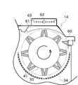
- FIG. 5 is a plan view of the main part of the threshing apparatus 14 showing the state of the handling cylinder 30, the cutting blade 60, and the dust feed valve 61.
- the cutting blades 60 are for cutting the cereals, and a plurality of cutting blades 60 are arranged on the left side of the handling cylinder 30 as shown in FIG. These cutting blades 60 are arranged side by side at predetermined intervals along the axial direction of the handling cylinder 30 from the vicinity of the upstream end of the handling cylinder 30 to the central portion in the axial direction. Further, as shown in FIG.
- the range in which the cutting blade 60 is disposed ranges from a position in the vicinity of the tooth handling teeth 41 arranged on the most upstream side in the handling cylinder 30 to the vicinity of the downstream end portion of the first chaff sheave 36. It has become.
- Each of the cutting blades 60 is disposed between paths around which the teeth 41 rotate due to the rotation of the cylinder 30. With this configuration, the grain can be threshed while cutting the cereal with the cutting blade 60, and the processed product can be effectively selected with the first chaff sheave 36.
- the dust feeding valves 61 are for adjusting the residence time of the processed material in the handling chamber, and a plurality of the dust feeding valves 61 are arranged above the handling cylinder 30 as shown in FIG.
- the dust supply valve 61 is rotatably supported on the ceiling surface of the handling chamber, and ends thereof are connected to each other by a bar member 64. When one dust supply valve 61 rotates, another dust supply valve is provided. 61 is also configured to rotate in conjunction.
- a work lever 62 is connected to the dust feed valve 61 arranged on the most upstream side, and by operating this work lever 62, the directions of the plurality of dust feed valves 61 can be changed all at once. .
- the threshing device 14 includes a lever guide 63 for holding the work lever 62 at a desired position. By locking the work lever 62 with the lever guide 63, the dust feeding valve 61 is set at an appropriate angle. Can be held in.
- the combine 10 is configured as a full-load type. Moreover, in the threshing apparatus 14 with which this combine 10 is provided, the teeth 41 of the handling cylinder 30 with which the said threshing apparatus 14 are arranged along the 1st spiral 81 which makes the handling cylinder 30 and an axis line correspond. Further, the tooth handling 41 and the tooth handling 41 adjacent to the tooth handling 41 in the axial direction of the handling cylinder 30 are arranged so as to have different phases and partially overlap when viewed in the axial direction.
- a series of teeth 41 in which adjacent teeth 41 partially overlap in the axial direction of the barrel 30 are the same as the first spiral 81, have the same winding direction, and have a second pitch larger than that of the first spiral 81. They are arranged along the spiral 82.
- a series of teeth 41 arranged along the second spiral 82 act on the threshing object being conveyed in order with a time difference. Therefore, it is possible to prevent a plurality of teeth 41 from colliding with a threshing object at the same time to generate instantaneous overload, noise and vibration, and to provide a combine 10 having excellent threshing performance and comfortable ride. it can.
- the tooth handling 41 is arrange
- the threshing apparatus 14 of the present embodiment includes a first chaff sheave 36 and a second chaff sheave 37 that are arranged below the handling cylinder 30 in order to select the grains falling from the handling cylinder 30. Further, the threshing device 14 is disposed in a range including at least a position from the vicinity of the tooth handling teeth 41 arranged on the most upstream side in the handling cylinder 30 to a position corresponding to the downstream end of the first chaff sheave 36. A blade 60 is provided. The cutting blade 60 is disposed between a path around which the plurality of teeth 41 are rotated by the rotation of the cylinder 30.
- the cutting blade 60 acts on the threshing object, so that the threshing work can be performed more effectively in combination with the continuous action of the tooth handling 41. Moreover, since a cutting blade is arrange
- the threshing device 14 of the present embodiment includes a dust feed valve 61 that is arranged in the vicinity of the handling cylinder 30 and that is adjustable in angle.
- This configuration allows the stagnation time in the handling cylinder 30 to be adjusted according to the conditions of the crop by adjusting the angle of the dust feed valve 61, so that the threshing performance can be exhibited more effectively.
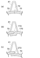
- FIG. 6 is an enlarged cross-sectional view showing a treatment cylinder and tooth treatment of a modified example.
- the peripheral surface of the handling cylinder in the modified example shown in FIG. 6 (a) is configured by connecting two plate-like members 70 (the halved portion) curved in a semicircular shape. At this time, the two plate-like members 70 are joined so that the end faces of the plate-like members 70 abut each other. Thereby, the unevenness
- the tooth handling 41 is formed by bending a round bar in the same manner as in the above embodiment, and one end thereof is fixed to the plate member 70 on one side and the other end is fixed to the plate member 70 on the other side. . Thereby, it can suppress that a processed material is clogged or caught in the said joint 72, and can reduce the frequency
- a joint 172 in which a part of the plate member 170 on the other side is bent and enters inside the plate member 70 on the one side can be formed.
- the unevenness formed on the peripheral surface of the handling cylinder 30 can be reduced, and the coupling force of the joint 172 can be easily enhanced.
- a part of the plurality of teeth 41 is arranged so as to straddle the joint 172 between the plate member 70 and the plate member 170.
- the plate-like member 70 on the other side enters the inside of the plate-like member 70 on the one side as shown in FIG. 6C.
- a seam 272 can also be formed.
- the tooth handling 41 can be arranged so as to straddle the joint 272.
- the peripheral surface of the handling drum is configured by connecting a plurality of plate-like members 70 curved in an arc shape. A part of the plurality of teeth 41 is arranged so as to straddle the joint 72 of the plate-like member 70.
- the peripheral surface of the handling cylinder 30 can be configured by joining the divided plate-like members 70, so that the handling cylinder 30 can be easily manufactured. Moreover, since the tooth handling 41 is arrange
- the teeth 41 arranged on the handling cylinder 30 are arranged on the first helix 81 and the second helix 82, but are not limited to this configuration, for example, two helix 81. , 82 can be additionally disposed at an appropriate place off one or both of the teeth. Further, it is not always necessary that the interval between the teeth 41 on the first helix 81 is constant, and the teeth 41 having a different interval may be disposed or a portion of the teeth 41 may be omitted. Can do.
- the pitch of the first spiral 81 and the second spiral 82 is constant, but the present invention is not limited to this configuration.
- the pitch of the first spiral 81 or the second spiral 82 can be changed near the downstream side of the handling cylinder 30.
- the cutting blade 60 is disposed up to the vicinity of the downstream end portion of the first chaff sheave 36, but this configuration can be changed.
- the range in which the cutting blade 60 is disposed can be extended to the vicinity of the downstream end portion of the second chaff sheave 37.
Landscapes
- Threshing Machine Elements (AREA)
- Life Sciences & Earth Sciences (AREA)
- Environmental Sciences (AREA)
Abstract
Description
30 扱胴
41 扱歯
60 切刃
61 送塵弁
81 第1螺旋
82 第2螺旋
Claims (4)
- 周面に複数の扱歯を有する扱胴によって穀稈を脱穀する全量投入型コンバインの脱穀装置において、
前記扱歯は、前記扱胴と軸線を一致させる第1の螺旋に沿って並べられるとともに、
前記扱歯と、その扱歯に対して前記扱胴の軸方向で隣り合う扱歯とが、その位相を異ならせるとともに当該軸方向に見て一部のみ重複するように配置され、隣り合う扱歯同士が前記扱胴の軸方向で一部重複する一連の扱歯が、前記第1の螺旋と同軸かつ巻き方向が同じで当該第1の螺旋よりピッチが大きい第2の螺旋に沿って並べられることを特徴とするコンバインの脱穀装置。 - 請求項1に記載のコンバインの脱穀装置であって、
前記扱胴から落下する穀粒を選別するために当該扱胴の下方に複数配置されるチャフシーブと、
扱胴において最も上流側に配置される前記扱歯の近傍位置から、前記チャフシーブのうち最も上流側に配置されるチャフシーブの下流側端部に相当する位置までを少なくとも含む範囲に配置される切刃と、
を備え、
前記切刃は、前記扱胴の回転によって複数の前記扱歯が周回する経路の間に配置されることを特徴とするコンバインの脱穀装置。 - 請求項1又は2に記載のコンバインの脱穀装置であって、
前記扱胴の近傍に配置された角度調節自在の送塵弁を備えることを特徴とするコンバインの脱穀装置。 - 請求項1から3までの何れか一項に記載のコンバインの脱穀装置であって、
前記扱胴の周面は、円弧状に湾曲された複数の板状部材を繋ぎ合わせて構成されており、複数の前記扱歯の一部は、前記板状部材の繋ぎ目を跨ぐように配置されることを特徴とするコンバインの脱穀装置。
Priority Applications (1)
| Application Number | Priority Date | Filing Date | Title |
|---|---|---|---|
| CN2009801099312A CN101977495A (zh) | 2008-03-24 | 2009-03-16 | 联合收割机的脱粒装置 |
Applications Claiming Priority (2)
| Application Number | Priority Date | Filing Date | Title |
|---|---|---|---|
| JP2008075623A JP5063429B2 (ja) | 2008-03-24 | 2008-03-24 | コンバインの脱穀装置 |
| JP2008-075623 | 2008-03-24 |
Publications (1)
| Publication Number | Publication Date |
|---|---|
| WO2009119035A1 true WO2009119035A1 (ja) | 2009-10-01 |
Family
ID=41113248
Family Applications (1)
| Application Number | Title | Priority Date | Filing Date |
|---|---|---|---|
| PCT/JP2009/001164 Ceased WO2009119035A1 (ja) | 2008-03-24 | 2009-03-16 | コンバインの脱穀装置 |
Country Status (4)
| Country | Link |
|---|---|
| JP (1) | JP5063429B2 (ja) |
| KR (1) | KR101604644B1 (ja) |
| CN (1) | CN101977495A (ja) |
| WO (1) | WO2009119035A1 (ja) |
Cited By (1)
| Publication number | Priority date | Publication date | Assignee | Title |
|---|---|---|---|---|
| CN104396460A (zh) * | 2014-11-24 | 2015-03-11 | 重庆五谷通用设备有限公司 | 一种防溅的小型水稻联合收割机脱粒筒 |
Families Citing this family (3)
| Publication number | Priority date | Publication date | Assignee | Title |
|---|---|---|---|---|
| CN103718744A (zh) * | 2014-01-02 | 2014-04-16 | 山东理工大学 | 一种绿豆联合作业收获机 |
| JP2018068145A (ja) * | 2016-10-25 | 2018-05-10 | 株式会社クボタ | 脱穀装置 |
| CN109121731A (zh) * | 2018-08-30 | 2019-01-04 | 绩溪袁稻农业产业科技有限公司 | 一种小型水稻脱粒机 |
Citations (7)
| Publication number | Priority date | Publication date | Assignee | Title |
|---|---|---|---|---|
| JPS5139063U (ja) * | 1974-09-18 | 1976-03-23 | ||
| JPS62164744U (ja) * | 1986-04-11 | 1987-10-20 | ||
| JPS63167722A (ja) * | 1986-12-27 | 1988-07-11 | 株式会社クボタ | 脱穀装置 |
| JPH10313656A (ja) * | 1997-05-20 | 1998-12-02 | Kubota Corp | コンバイン |
| JP2001352825A (ja) * | 2000-06-14 | 2001-12-25 | Yanmar Agricult Equip Co Ltd | コンバイン |
| JP2005253388A (ja) * | 2004-03-12 | 2005-09-22 | Kubota Corp | 脱穀装置の扱胴 |
| JP2005304427A (ja) * | 2004-04-23 | 2005-11-04 | Kubota Corp | 全稈投入型脱穀機 |
Family Cites Families (1)
| Publication number | Priority date | Publication date | Assignee | Title |
|---|---|---|---|---|
| JPH09187152A (ja) * | 1996-01-10 | 1997-07-22 | Kubota Corp | 排ワラ細断装置 |
-
2008
- 2008-03-24 JP JP2008075623A patent/JP5063429B2/ja active Active
-
2009
- 2009-03-16 KR KR1020107020511A patent/KR101604644B1/ko not_active Expired - Fee Related
- 2009-03-16 CN CN2009801099312A patent/CN101977495A/zh active Pending
- 2009-03-16 WO PCT/JP2009/001164 patent/WO2009119035A1/ja not_active Ceased
Patent Citations (7)
| Publication number | Priority date | Publication date | Assignee | Title |
|---|---|---|---|---|
| JPS5139063U (ja) * | 1974-09-18 | 1976-03-23 | ||
| JPS62164744U (ja) * | 1986-04-11 | 1987-10-20 | ||
| JPS63167722A (ja) * | 1986-12-27 | 1988-07-11 | 株式会社クボタ | 脱穀装置 |
| JPH10313656A (ja) * | 1997-05-20 | 1998-12-02 | Kubota Corp | コンバイン |
| JP2001352825A (ja) * | 2000-06-14 | 2001-12-25 | Yanmar Agricult Equip Co Ltd | コンバイン |
| JP2005253388A (ja) * | 2004-03-12 | 2005-09-22 | Kubota Corp | 脱穀装置の扱胴 |
| JP2005304427A (ja) * | 2004-04-23 | 2005-11-04 | Kubota Corp | 全稈投入型脱穀機 |
Cited By (1)
| Publication number | Priority date | Publication date | Assignee | Title |
|---|---|---|---|---|
| CN104396460A (zh) * | 2014-11-24 | 2015-03-11 | 重庆五谷通用设备有限公司 | 一种防溅的小型水稻联合收割机脱粒筒 |
Also Published As
| Publication number | Publication date |
|---|---|
| JP2009225726A (ja) | 2009-10-08 |
| KR20100126383A (ko) | 2010-12-01 |
| CN101977495A (zh) | 2011-02-16 |
| JP5063429B2 (ja) | 2012-10-31 |
| KR101604644B1 (ko) | 2016-03-18 |
Similar Documents
| Publication | Publication Date | Title |
|---|---|---|
| WO2009154030A1 (ja) | コンバインの脱穀部 | |
| JP5063429B2 (ja) | コンバインの脱穀装置 | |
| JP6995132B2 (ja) | 扱胴 | |
| JP6472357B2 (ja) | コンバイン | |
| JP5179974B2 (ja) | コンバインの脱穀部 | |
| JP5336113B2 (ja) | コンバインの脱穀部 | |
| JP5355943B2 (ja) | コンバインの脱穀部 | |
| JP6215145B2 (ja) | コンバイン | |
| JP5797940B2 (ja) | コンバインの扱胴 | |
| JP6667230B2 (ja) | コンバイン | |
| JP6335514B2 (ja) | 脱穀装置 | |
| JP5796621B2 (ja) | 脱穀装置の扱胴 | |
| JP2014014330A (ja) | 脱穀装置 | |
| JP5355944B2 (ja) | コンバインの脱穀部 | |
| JP4651027B2 (ja) | 再脱穀処理装置,脱穀装置及びコンバイン | |
| JP5622115B2 (ja) | 脱穀装置の扱胴 | |
| JP2010011780A (ja) | コンバインの脱穀部 | |
| JP2016059315A (ja) | 脱穀装置 | |
| JP5843714B2 (ja) | 脱穀装置 | |
| JP7039445B2 (ja) | コンバイン | |
| JP2017029113A (ja) | 脱穀装置 | |
| JP5797952B2 (ja) | コンバインの扱胴 | |
| JP2017139985A (ja) | 排稈切断処理装置 | |
| JP6109384B2 (ja) | 脱穀装置 | |
| JP4646004B2 (ja) | 再脱穀処理装置,脱穀装置及びコンバイン |
Legal Events
| Date | Code | Title | Description |
|---|---|---|---|
| WWE | Wipo information: entry into national phase |
Ref document number: 200980109931.2 Country of ref document: CN |
|
| 121 | Ep: the epo has been informed by wipo that ep was designated in this application |
Ref document number: 09726310 Country of ref document: EP Kind code of ref document: A1 |
|
| DPE1 | Request for preliminary examination filed after expiration of 19th month from priority date (pct application filed from 20040101) | ||
| ENP | Entry into the national phase |
Ref document number: 20107020511 Country of ref document: KR Kind code of ref document: A |
|
| NENP | Non-entry into the national phase |
Ref country code: DE |
|
| 122 | Ep: pct application non-entry in european phase |
Ref document number: 09726310 Country of ref document: EP Kind code of ref document: A1 |