WO2009119028A1 - 画像記録装置 - Google Patents
画像記録装置 Download PDFInfo
- Publication number
- WO2009119028A1 WO2009119028A1 PCT/JP2009/001117 JP2009001117W WO2009119028A1 WO 2009119028 A1 WO2009119028 A1 WO 2009119028A1 JP 2009001117 W JP2009001117 W JP 2009001117W WO 2009119028 A1 WO2009119028 A1 WO 2009119028A1
- Authority
- WO
- WIPO (PCT)
- Prior art keywords
- cut
- recording medium
- introduction
- speed
- pair
- Prior art date
- Legal status (The legal status is an assumption and is not a legal conclusion. Google has not performed a legal analysis and makes no representation as to the accuracy of the status listed.)
- Ceased
Links
Images

Classifications
-
- B—PERFORMING OPERATIONS; TRANSPORTING
- B41—PRINTING; LINING MACHINES; TYPEWRITERS; STAMPS
- B41J—TYPEWRITERS; SELECTIVE PRINTING MECHANISMS, i.e. MECHANISMS PRINTING OTHERWISE THAN FROM A FORME; CORRECTION OF TYPOGRAPHICAL ERRORS
- B41J11/00—Devices or arrangements of selective printing mechanisms, e.g. ink-jet printers or thermal printers, for supporting or handling copy material in sheet or web form
- B41J11/66—Applications of cutting devices
- B41J11/70—Applications of cutting devices cutting perpendicular to the direction of paper feed
-
- Y—GENERAL TAGGING OF NEW TECHNOLOGICAL DEVELOPMENTS; GENERAL TAGGING OF CROSS-SECTIONAL TECHNOLOGIES SPANNING OVER SEVERAL SECTIONS OF THE IPC; TECHNICAL SUBJECTS COVERED BY FORMER USPC CROSS-REFERENCE ART COLLECTIONS [XRACs] AND DIGESTS
- Y10—TECHNICAL SUBJECTS COVERED BY FORMER USPC
- Y10T—TECHNICAL SUBJECTS COVERED BY FORMER US CLASSIFICATION
- Y10T83/00—Cutting
- Y10T83/444—Tool engages work during dwell of intermittent workfeed
- Y10T83/4529—With uninterrupted flow of work from supply source
-
- Y—GENERAL TAGGING OF NEW TECHNOLOGICAL DEVELOPMENTS; GENERAL TAGGING OF CROSS-SECTIONAL TECHNOLOGIES SPANNING OVER SEVERAL SECTIONS OF THE IPC; TECHNICAL SUBJECTS COVERED BY FORMER USPC CROSS-REFERENCE ART COLLECTIONS [XRACs] AND DIGESTS
- Y10—TECHNICAL SUBJECTS COVERED BY FORMER USPC
- Y10T—TECHNICAL SUBJECTS COVERED BY FORMER US CLASSIFICATION
- Y10T83/00—Cutting
- Y10T83/444—Tool engages work during dwell of intermittent workfeed
- Y10T83/4539—Means to change tool position, or length or datum position of work- or tool-feed increment
- Y10T83/4541—With means to vary magnitude of work-feed increment
-
- Y—GENERAL TAGGING OF NEW TECHNOLOGICAL DEVELOPMENTS; GENERAL TAGGING OF CROSS-SECTIONAL TECHNOLOGIES SPANNING OVER SEVERAL SECTIONS OF THE IPC; TECHNICAL SUBJECTS COVERED BY FORMER USPC CROSS-REFERENCE ART COLLECTIONS [XRACs] AND DIGESTS
- Y10—TECHNICAL SUBJECTS COVERED BY FORMER USPC
- Y10T—TECHNICAL SUBJECTS COVERED BY FORMER US CLASSIFICATION
- Y10T83/00—Cutting
- Y10T83/465—Cutting motion of tool has component in direction of moving work
- Y10T83/474—With work feed speed regulator
-
- Y—GENERAL TAGGING OF NEW TECHNOLOGICAL DEVELOPMENTS; GENERAL TAGGING OF CROSS-SECTIONAL TECHNOLOGIES SPANNING OVER SEVERAL SECTIONS OF THE IPC; TECHNICAL SUBJECTS COVERED BY FORMER USPC CROSS-REFERENCE ART COLLECTIONS [XRACs] AND DIGESTS
- Y10—TECHNICAL SUBJECTS COVERED BY FORMER USPC
- Y10T—TECHNICAL SUBJECTS COVERED BY FORMER US CLASSIFICATION
- Y10T83/00—Cutting
- Y10T83/647—With means to convey work relative to tool station
- Y10T83/6475—With means to regulate work-feed speed
Definitions
- the present invention relates to an image recording apparatus for recording an image by fixing ink on a recording medium such as paper or film.
- An image recording apparatus that records a color image by discharging ink onto a continuous recording medium in which paper or film is wound into a roll or a recording medium (cut paper) that has been cut into a predetermined size is known. It has been.
- such an image recording apparatus records, for example, images having different contents for each recording medium forming each page while transporting the recording medium at a high speed of several tens to several hundreds m / min. Further, in the case of a continuous medium on which an image is recorded, it is cut and discharged for each page.
- various methods are known as sorting methods for each job using cut paper cut to a predetermined length.
- the paper discharged to the stacker is offset and discharged, or the end of the cut paper is marked.
- Patent Document 1 discloses a technique that enables easy paper sorting by reversing the direction of printed data.
- Patent Document 1 when cut sheets of a predetermined length are stacked and continuously stacked, the sizes of the sheets are all the same, so that it is difficult to identify each job, for example. Also, a method of marking an identification mark on the end face of the paper has been proposed, but depending on the position of the stacker guide, it may be difficult to identify.
- Japanese Patent Application Laid-Open No. 2004-260260 it seems easy to identify each job at first glance. However, in actuality, it is difficult to identify each job when sheets are stacked. Japanese Patent Laid-Open No. 5-64925
- the present invention provides an image recording apparatus capable of recognizing job breaks at first glance.
- the image recording apparatus of the present invention comprises: A transport unit that transports the continuous medium recorded by the image recording unit at a predetermined tension and speed; A cutting part having a cut-side rotating body and a receiving-side rotating body, which are arranged to face each other so as to cut the continuous medium and are rotated at a constant rotation speed; An introduction unit having a pair of introduction rotators disposed between the conveyance unit and the cutting unit and sandwiching the continuous medium and introducing the continuous medium into the cutting unit with a tension smaller than the tension in the conveyance unit; Temporarily stopping or decelerating the pair of introduction rotors, temporarily reducing the introduction amount of the continuous medium into the cutting portion, introducing it with a cut dimension shorter than the normal cut dimension, and then Control means for starting or accelerating the introduction rotating body at a timing to increase the introduction amount of the continuous medium into the cutting portion and to introduce the continuous medium longer than a normal cut size.
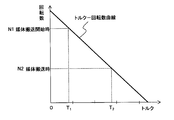
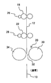
- FIG. 1 is a diagram illustrating an overall configuration of an image recording apparatus according to an embodiment. It is a figure which shows the torque-rotation speed curve of the drive motor which drives an introduction roller pair. It is explanatory drawing for outputting the paper cut into the normal length.
- FIG. 10 is an explanatory diagram for outputting a sheet cut shorter than a predetermined for identification for each job.
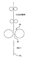
- FIG. 10 is an explanatory diagram for outputting a sheet cut longer than a predetermined length for identification for each job. It is a figure which shows each length of the cut paper discharged
- (A)-(f) is a figure which shows the time chart of this embodiment.
- FIG. 3 is a diagram illustrating sheets stacked on a sheet stacker. It is a figure which shows the state which attached
- FIG. 1 shows the overall configuration of the image recording apparatus in the present embodiment.
- the image recording apparatus 10 includes a medium supply unit 14 that accommodates a continuous roll-shaped recording medium 12, an image recording unit 16 that records an image on the recording medium 12, and a recording medium on which an image is recorded by the image recording unit 16. 12, a conveying unit 17 that conveys the recording medium 12 at a predetermined tension and speed, a cutting unit 20 that cuts the recording medium 12 into a predetermined length, an introduction unit 21 disposed between the conveying unit 17 and the cutting unit 20, and the entire apparatus And a control unit 25 as a control means for controlling the above.
- a paper stacker 24 for stacking the cut sheets 13 cut by the cutting unit 20 is provided at the subsequent stage of the cutting unit 20.
- the transport unit 17 includes nip roller pairs 18 and 18 that sandwich the continuous recording medium 12 and transport it toward the transport downstream side.
- the nip roller pair 18, 18 is driven by a drive motor 26.
- the recording medium 12 is conveyed downstream of the conveyance with a predetermined tension by the nip roller pairs 18 and 18.
- the cutting unit 20 includes a cut roller 30 serving as a cut-side rotating body that is disposed so as to be capable of cutting the recording medium 12 and is rotating at a constant rotation speed, and an anvil roller 34 serving as a receiving-side rotating body. .
- a cut blade 32 is provided on the outer peripheral surface of the cut roller 30, and the recording medium 12 is cut by the cut blade 32.
- the introduction unit 21 is disposed between the conveyance unit 17 and the cutting unit 20 and serves as a pair of introduction rotators that sandwich the recording medium 12 and introduce the recording medium 12 to the cutting unit 20 with a tension smaller than the tension in the conveyance unit 17.
- Introducing roller pair 22, 22 The introduction roller pair 22, 22 is driven by a drive motor 28.
- the control unit 25 temporarily stops or decelerates the introduction roller pair 22, 22 to temporarily reduce the introduction amount of the recording medium 12 to the cutting unit 20, and introduces the cut size shorter than the normal cut size. Thereafter, the introduction roller pair 22, 22 is activated or accelerated at a predetermined timing, and the amount of introduction of the recording medium 12 into the cutting portion 20 is increased so as to be introduced longer than the normal cut size.
- the recording medium 12 is accommodated in the medium supply unit 14 in a state of being wound in a roll shape. Back tension is applied to the roll-shaped recording medium 12 by a friction applying mechanism (not shown).
- the nip roller pairs 18 and 18 convey the recording medium 12 while keeping the conveyance speed of the recording medium 12 constant.
- the image recording unit 16 records an image on the recording medium 12 thus conveyed.
- the rotary cutting unit 20 is used as a method of cutting continuous paper for each predetermined printing unit.
- the cutting unit 20 rotates the cut roller 30 and the anvil roller 34 at a constant speed synchronized with the conveyance speed of the recording medium 12, whereby the cutting blade 32 is pressed against the anvil roller 34, and the recording medium 12 is moved to a predetermined level. Cut to paper size.
- the control unit 25 performs drive control of the image recording unit 16, the conveyance unit 17, the cutting unit 20, and the like in response to an image recording command from a host device (not shown) such as a personal computer.
- FIG. 2 shows a torque-rotation speed curve during constant current driving of the drive motor 28 that drives the introduction roller pair 22, 22.
- the drive method of the drive motor 28 is called constant torque drive (or constant current drive), and only a constant current is passed through the motor, speed control is not performed, and therefore a servo circuit is not required.
- the torque that generates a lower tension than the tension generated by the transport unit 17 and the rotational speed in the no-load state are set to characteristics that provide a transport speed that exceeds the normal transport speed of the recording medium 12. .
- the tension generated by the pair of nip rollers 18 and 18 and the transport unit 17 during medium transport causes a high load (high torque T2).
- high torque T2 high torque
- the drive motor 28 has a high rotational speed N1 (no-load rotational speed) and rapidly conveys the recording medium 12 to the cutting unit 20.
- N1 no-load rotational speed
- the drive motor 28 that drives the introduction roller pair 22 and 22 is a constant torque drive, but a constant voltage drive may be used as long as the motor can obtain predetermined characteristics with no-load rotation speed and torque.
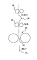
- Figure 3A ⁇ 3C are respectively is a description diagram for outputting a normal sheet 13 is cut to length, the paper 13 1 that is shorter cut than a predetermined paper 13 2 which is longer cut than the predetermined .
- the drive motor 28 that drives the introduction roller pair 22, 22 is a nip roller pair.
- the recording medium 12 is rotated in accordance with the conveyance speed of the recording medium 12 defined by 18. This is because the rotational torque of the drive motor 28 that drives the introduction roller pair 22, 22 is weaker than the rotational torque of the drive motor 26 that drives the nip roller pair 18, 18 on the upstream side of conveyance.
- the cut roller 30 and the anvil roller 34 have a larger inertia force than the nip roller pair 18 and the like, and rotate at a constant speed at a predetermined speed.
- the recording medium 12 is cut by being introduced between the cut roller 30 and the anvil roller 34. At this time, the recording medium 12 is cut by the length of the distance that the cut roller 30 moves during the time required for one rotation.
- the introduction roller pair 22 and 22 is subjected to rotation stoppage or deceleration control for a predetermined time. Then, the supply amount of the recording medium 12 introduced into the cutting unit 20 is reduced during the stop or deceleration time.
- the cut roller 30 and the anvil roller 34 rotate at a constant speed during this period. As a result, the recording medium 12 is cut as a short-cut sheet 13 1 is shorter than a predetermined length, to be output from the cutting section 20.
- the conveyance of the recording medium 12 by the nip roller pairs 18 and 18 continues.
- the recording medium 12 stagnates in a state where a slack portion 36 that is curved is formed between the nip roller pair 18, 18 and the introduction roller pair 22, 22.
- the stop or deceleration of the introduction roller pair 22, 22 is released. Then, the recording medium 12 that has been bent and slackened is not affected by the nip roller pair 18, 18, and the drive motor 28 of the introduction roller pair 22, 22 is temporarily in a very light load state. Therefore, the drive motor 28 rotates at a high speed until the slack of the recording medium 12 is eliminated based on the rotation speed-torque characteristic of FIG. Thus, the introduction roller pair 22, 22 supplies the recording medium 12 to the cutting portion 20 side by an extra length corresponding to the slack portion 36.
- the recording medium 12 is cut as long a length cut sheet 13 2 than a predetermined length, to be output from the cutting section 20.
- L 200 mm
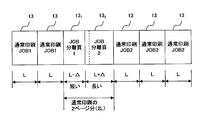
- FIG. 4 is a diagram illustrating the lengths of the cut sheets 13 discharged to the sheet stacker 24.
- short-cut sheet 13 1 and the long cut sheet 13 2 as a separation page is discharged between the job 1 and (JOB1) and job 2 (JOB2).
- the short-cut sheet 13 1 and the long cut sheet 13 2 by the process described above, when the length of a normal cut sheet 13 is L, the length of the short cut sheet 13 1 is shorter L-delta than normal , and the length of the major cutting sheet 13 2 is long L + delta than usual.
- These short-cut sheet 13 1 and the long cut sheet 13 2 is composed of a set.
- the short-cut sheet 13 1 and the long cut sheet 13 2 identifies the boundary between job 1 and job 2.
- the conveyance speed of the recording medium 12 is defined by the nip roller pair 18. Therefore, the rotational speeds of the cut roller 30 and the anvil roller 34 are determined in synchronization with the speed of the nip roller pair 18, 18. For this reason, normally, the recording medium 12 on which image recording has been performed based on the job information is cut to a predetermined length. Further, even in a short-cut sheet 13 1 and the long cut sheet 13 2 output period, the linear velocity of the nip roller pair 18 (i.e., the conveying speed of the recording medium 12) the linear speed of the cut roller 30 and anvil roller 34, normal The same as when recording a job image.
- the time during which the rotation of the introduction roller pair 22 is stopped or decelerated is shorter than the conveyance time for one sheet of normal printing, and the time required for starting or accelerating the introduction roller pair 22 is also one sheet of normal printing paper. is shorter than the transport time is shorter short cut sheet 13 1 and long length cut sheet 13 2 total length of a set corresponds to two pages of the length of the normal printing paper (2L).
- the ratio of short-cut sheet 13 1 and the long cut sheet 13 second length can be adjusted by changing the time to stop or decelerate the introduction roller pair 22. In this way, the sum of the short-cut sheet 13 1 and the long cut sheet 13 second length, can be cut 2L, 3L, the length of ....
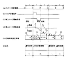
- FIGS. 5A to 5F show time charts of the present embodiment.
- FIG. 5A shows the rotation period t of the cut roller 30 that rotates at a constant speed. That is, every time the cut roller 30 makes one rotation, the recording medium 12 is cut by the cut blade 32 provided on the outer periphery thereof.
- the amount of the recording medium 12 introduced into the cutting unit 20 is reduced (L ⁇ ), but the cut roller 30 rotates at a constant speed. Is cut to a length (L ⁇ ) shorter than the normal length L.
- the drive motor 28 of the introduction roller pair 22 and 22 starts to start. At this time, a slack portion 36 of the recording medium 12 exists on the upstream side of the introduction roller pair 22, 22. For this reason, since the load on the drive motor 28 becomes extremely light, the drive motor 28 rotates at a high speed (see FIG. 5D).
- the amount of the recording medium 12 introduced into the cutting unit 20 increases (L + ⁇ ), and the cutting roller 30 rotates at a constant speed, so that the recording medium 12 is cut with a longer length (L + ⁇ ) than usual. (See FIG. 5 (e)).
- the slack portion 36 of the recording medium 12 disappears, the recording medium 12 is cut with a normal length L thereafter.
- FIG. 5F shows a state in which the discharged cut sheets 13 are arranged in time series. That is, the conventional cut sheet 13 is cleaved at the period t, the job separation period is cut into a short-cut sheet 13 1 and the long cut sheet 13 2 at a period 2t.
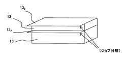
- FIG. 6 shows the sheets that are discharged and stacked in large quantities on the sheet stacker 24.
- Long cut sheet 13 2 is seen that projects around the transport direction from a plurality of stacked media.
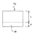
- Figure 7 shows a state in which a mark 38 for marker to the short portion of the conveying direction of the long cut sheet 13 2.
- the mark 38 is recorded, for example, M-color, it may be recorded on the entire area of the long cut sheet 13 2. In this way, not only by changing the length of the sheet but also by coloring the predetermined area, it is possible to reliably recognize the breaks in the job.
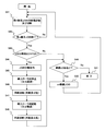
- FIG. 8 shows a flowchart of the present embodiment.
- step 41 when an image recording command and a disconnection command for the nth job (JOB) are issued from the host device, in S42, whether or not the nth job has ended. Judging. If No (not finished), the process returns to S41, and if Yes (end), the process proceeds to S43.
- S43 it is determined whether or not to output a job separation page. If No, the process proceeds to S49, and if Yes, the process proceeds to S44. That is, if the information from the host device indicates that a separation page should be added, the process proceeds to S44, and if not, the process proceeds to S49.
- the cut roller 30 and the anvil roller 34 have a structure with a high moment of inertia.
- the introduction roller pair 22 temporarily decreases the introduction amount of the stop or deceleration to the recording medium 12 by being conveyed to the cutting disconnectable part recording medium 12 in a short-cut sheet 13 1 is shorter than the normal 20 was introduced. Furthermore, the subsequent predetermined timing the introduction roller pair 22 is started or accelerated, and as to introduce the recording medium 12 to be able to cut the cut portion 20 to the long length cut sheet 13 2 than usual. Thus, it was possible to output the long cut sheet 13 2 than usual break of jobs, it is possible to recognize a break of jobs at a glance.
Landscapes
- Handling Of Sheets (AREA)
- Ink Jet (AREA)
Priority Applications (2)
| Application Number | Priority Date | Filing Date | Title |
|---|---|---|---|
| CN2009801102654A CN101977776A (zh) | 2008-03-28 | 2009-03-12 | 图像记录装置 |
| US12/885,689 US8231290B2 (en) | 2008-03-28 | 2010-09-20 | Apparatus and method for controlling cutting length in an image recording apparatus |
Applications Claiming Priority (2)
| Application Number | Priority Date | Filing Date | Title |
|---|---|---|---|
| JP2008087265A JP5020877B2 (ja) | 2008-03-28 | 2008-03-28 | 画像記録装置 |
| JP2008-087265 | 2008-03-28 |
Related Child Applications (1)
| Application Number | Title | Priority Date | Filing Date |
|---|---|---|---|
| US12/885,689 Continuation US8231290B2 (en) | 2008-03-28 | 2010-09-20 | Apparatus and method for controlling cutting length in an image recording apparatus |
Publications (1)
| Publication Number | Publication Date |
|---|---|
| WO2009119028A1 true WO2009119028A1 (ja) | 2009-10-01 |
Family
ID=41113242
Family Applications (1)
| Application Number | Title | Priority Date | Filing Date |
|---|---|---|---|
| PCT/JP2009/001117 Ceased WO2009119028A1 (ja) | 2008-03-28 | 2009-03-12 | 画像記録装置 |
Country Status (4)
| Country | Link |
|---|---|
| US (1) | US8231290B2 (enExample) |
| JP (1) | JP5020877B2 (enExample) |
| CN (1) | CN101977776A (enExample) |
| WO (1) | WO2009119028A1 (enExample) |
Families Citing this family (4)
| Publication number | Priority date | Publication date | Assignee | Title |
|---|---|---|---|---|
| US9296197B2 (en) * | 2012-07-17 | 2016-03-29 | Kabushiki Kaisha Tokyo Kikai Seisakusho | Print product production device |
| EP2687378B1 (en) | 2012-07-18 | 2015-02-11 | Kabushiki Kaisha Tokyo Kikai Seisakusho | Print product production device |
| CN104139615A (zh) * | 2014-08-06 | 2014-11-12 | 常州汉威信电子科技有限公司 | 切纸和打印同步工作的打印机 |
| CN112192629A (zh) * | 2020-09-23 | 2021-01-08 | 周桂琴 | 一种止血带截取装置 |
Citations (3)
| Publication number | Priority date | Publication date | Assignee | Title |
|---|---|---|---|---|
| JPH04251074A (ja) * | 1990-06-07 | 1992-09-07 | Roll Syst Inc | 印刷された連続的な紙ウェブの出力された積み重ね体の折り丁を分類しかつ分離し更に標識を付する方法並びにその装置 |
| JPH1028198A (ja) * | 1996-07-10 | 1998-01-27 | Canon Inc | 画像形成装置および方法 |
| JP2003237193A (ja) * | 2002-02-21 | 2003-08-27 | Olympus Optical Co Ltd | プリントシステムおよびプリント仕分け方法 |
Family Cites Families (8)
| Publication number | Priority date | Publication date | Assignee | Title |
|---|---|---|---|---|
| US2315976A (en) * | 1941-04-14 | 1943-04-06 | Inland Steel Co | Apparatus for operating on sheet material |
| US3083602A (en) * | 1961-01-13 | 1963-04-02 | West Virginia Pulp & Paper Co | Precise web metering device |
| GB2036700B (en) * | 1978-11-14 | 1983-05-11 | Gd Spa | Web feeding and cutting device |
| US4809573A (en) * | 1987-10-26 | 1989-03-07 | Marquip. Inc. | Adaptive torque control of cutoff knife pull roll |
| JP2542255B2 (ja) * | 1989-05-01 | 1996-10-09 | ナスコ株式会社 | シャ―ライン |
| JPH0564925A (ja) | 1991-09-09 | 1993-03-19 | Ricoh Co Ltd | 画像形成装置 |
| DE10011006A1 (de) * | 2000-03-07 | 2001-09-27 | Boewe Systec Ag | Vorrichtung zum Schneiden von Papierbahnen |
| JP2010155388A (ja) * | 2008-12-26 | 2010-07-15 | Olympus Corp | 画像記録装置、及び画像記録装置の制御方法 |
-
2008
- 2008-03-28 JP JP2008087265A patent/JP5020877B2/ja not_active Expired - Fee Related
-
2009
- 2009-03-12 WO PCT/JP2009/001117 patent/WO2009119028A1/ja not_active Ceased
- 2009-03-12 CN CN2009801102654A patent/CN101977776A/zh active Pending
-
2010
- 2010-09-20 US US12/885,689 patent/US8231290B2/en not_active Expired - Fee Related
Patent Citations (3)
| Publication number | Priority date | Publication date | Assignee | Title |
|---|---|---|---|---|
| JPH04251074A (ja) * | 1990-06-07 | 1992-09-07 | Roll Syst Inc | 印刷された連続的な紙ウェブの出力された積み重ね体の折り丁を分類しかつ分離し更に標識を付する方法並びにその装置 |
| JPH1028198A (ja) * | 1996-07-10 | 1998-01-27 | Canon Inc | 画像形成装置および方法 |
| JP2003237193A (ja) * | 2002-02-21 | 2003-08-27 | Olympus Optical Co Ltd | プリントシステムおよびプリント仕分け方法 |
Also Published As
| Publication number | Publication date |
|---|---|
| US8231290B2 (en) | 2012-07-31 |
| US20110008092A1 (en) | 2011-01-13 |
| JP5020877B2 (ja) | 2012-09-05 |
| JP2009241262A (ja) | 2009-10-22 |
| CN101977776A (zh) | 2011-02-16 |
Similar Documents
| Publication | Publication Date | Title |
|---|---|---|
| US8935980B2 (en) | Systems and methods of printing to a web substrate | |
| US8657436B2 (en) | Media conveyance device, printing device, and media conveyance method | |
| JP5020877B2 (ja) | 画像記録装置 | |
| US20210276349A1 (en) | Printing apparatus, control method, and non-transitory computer-readable storage medium | |
| CN102896917B (zh) | 输送装置、印刷装置及输送方法 | |
| JP2017024248A (ja) | インクジェットプリンター、それを用いた印字方法及び自動紙通し方法 | |
| JP2010155388A (ja) | 画像記録装置、及び画像記録装置の制御方法 | |
| JP2005089057A (ja) | シート状記録材料の搬送方法及び装置 | |
| JP2012000815A (ja) | 画像記録装置、及び画像記録装置の制御方法 | |
| CN101778788B (zh) | 具有并行传送胶带的印刷机折页器 | |
| US6517200B1 (en) | Transport buffer having force limiting drive means and method | |
| JP6071339B2 (ja) | 熱転写記録装置 | |
| CN211994698U (zh) | 印刷装置 | |
| CN112208222B (zh) | 印刷装置及印刷方法 | |
| JP5834614B2 (ja) | 搬送装置、印刷装置、及び搬送方法 | |
| CN114375260B (zh) | 打印装置 | |
| JP2006056643A (ja) | 記録媒体の給送方法、および記録装置 | |
| JP5791417B2 (ja) | 記録装置 | |
| JP6618088B2 (ja) | 印字方法及び自動紙通し方法 | |
| JP2023081713A (ja) | 記録装置及び記録方法 | |
| JP2025146094A (ja) | プリンタ装置 | |
| JP2024155200A (ja) | 記録装置 | |
| JP6618285B2 (ja) | シート搬送装置および処理装置 | |
| JP2022166741A (ja) | 表示物作成装置 | |
| JP2013170024A (ja) | 搬送装置、印刷装置、及び搬送方法 |
Legal Events
| Date | Code | Title | Description |
|---|---|---|---|
| WWE | Wipo information: entry into national phase |
Ref document number: 200980110265.4 Country of ref document: CN |
|
| 121 | Ep: the epo has been informed by wipo that ep was designated in this application |
Ref document number: 09724114 Country of ref document: EP Kind code of ref document: A1 |
|
| NENP | Non-entry into the national phase |
Ref country code: DE |
|
| 122 | Ep: pct application non-entry in european phase |
Ref document number: 09724114 Country of ref document: EP Kind code of ref document: A1 |