WO2009113421A1 - エンジン - Google Patents
エンジン Download PDFInfo
- Publication number
- WO2009113421A1 WO2009113421A1 PCT/JP2009/053880 JP2009053880W WO2009113421A1 WO 2009113421 A1 WO2009113421 A1 WO 2009113421A1 JP 2009053880 W JP2009053880 W JP 2009053880W WO 2009113421 A1 WO2009113421 A1 WO 2009113421A1
- Authority
- WO
- WIPO (PCT)
- Prior art keywords
- decrease rate
- increase
- appropriate
- speed
- fuel injection
- Prior art date
Links
Images


Classifications
-
- F—MECHANICAL ENGINEERING; LIGHTING; HEATING; WEAPONS; BLASTING
- F02—COMBUSTION ENGINES; HOT-GAS OR COMBUSTION-PRODUCT ENGINE PLANTS
- F02D—CONTROLLING COMBUSTION ENGINES
- F02D41/00—Electrical control of supply of combustible mixture or its constituents
- F02D41/0002—Controlling intake air
- F02D41/0007—Controlling intake air for control of turbo-charged or super-charged engines
-
- F—MECHANICAL ENGINEERING; LIGHTING; HEATING; WEAPONS; BLASTING
- F02—COMBUSTION ENGINES; HOT-GAS OR COMBUSTION-PRODUCT ENGINE PLANTS
- F02D—CONTROLLING COMBUSTION ENGINES
- F02D23/00—Controlling engines characterised by their being supercharged
- F02D23/02—Controlling engines characterised by their being supercharged the engines being of fuel-injection type
-
- F—MECHANICAL ENGINEERING; LIGHTING; HEATING; WEAPONS; BLASTING
- F02—COMBUSTION ENGINES; HOT-GAS OR COMBUSTION-PRODUCT ENGINE PLANTS
- F02D—CONTROLLING COMBUSTION ENGINES
- F02D41/00—Electrical control of supply of combustible mixture or its constituents
- F02D41/24—Electrical control of supply of combustible mixture or its constituents characterised by the use of digital means
- F02D41/2406—Electrical control of supply of combustible mixture or its constituents characterised by the use of digital means using essentially read only memories
- F02D41/2425—Particular ways of programming the data
- F02D41/2429—Methods of calibrating or learning
- F02D41/2451—Methods of calibrating or learning characterised by what is learned or calibrated
- F02D41/2464—Characteristics of actuators
- F02D41/2467—Characteristics of actuators for injectors
-
- F—MECHANICAL ENGINEERING; LIGHTING; HEATING; WEAPONS; BLASTING
- F02—COMBUSTION ENGINES; HOT-GAS OR COMBUSTION-PRODUCT ENGINE PLANTS
- F02D—CONTROLLING COMBUSTION ENGINES
- F02D41/00—Electrical control of supply of combustible mixture or its constituents
- F02D41/30—Controlling fuel injection
- F02D41/38—Controlling fuel injection of the high pressure type
- F02D41/40—Controlling fuel injection of the high pressure type with means for controlling injection timing or duration
-
- F—MECHANICAL ENGINEERING; LIGHTING; HEATING; WEAPONS; BLASTING
- F02—COMBUSTION ENGINES; HOT-GAS OR COMBUSTION-PRODUCT ENGINE PLANTS
- F02B—INTERNAL-COMBUSTION PISTON ENGINES; COMBUSTION ENGINES IN GENERAL
- F02B37/00—Engines characterised by provision of pumps driven at least for part of the time by exhaust
- F02B37/12—Control of the pumps
-
- Y—GENERAL TAGGING OF NEW TECHNOLOGICAL DEVELOPMENTS; GENERAL TAGGING OF CROSS-SECTIONAL TECHNOLOGIES SPANNING OVER SEVERAL SECTIONS OF THE IPC; TECHNICAL SUBJECTS COVERED BY FORMER USPC CROSS-REFERENCE ART COLLECTIONS [XRACs] AND DIGESTS
- Y02—TECHNOLOGIES OR APPLICATIONS FOR MITIGATION OR ADAPTATION AGAINST CLIMATE CHANGE
- Y02T—CLIMATE CHANGE MITIGATION TECHNOLOGIES RELATED TO TRANSPORTATION
- Y02T10/00—Road transport of goods or passengers
- Y02T10/10—Internal combustion engine [ICE] based vehicles
- Y02T10/12—Improving ICE efficiencies
-
- Y—GENERAL TAGGING OF NEW TECHNOLOGICAL DEVELOPMENTS; GENERAL TAGGING OF CROSS-SECTIONAL TECHNOLOGIES SPANNING OVER SEVERAL SECTIONS OF THE IPC; TECHNICAL SUBJECTS COVERED BY FORMER USPC CROSS-REFERENCE ART COLLECTIONS [XRACs] AND DIGESTS
- Y02—TECHNOLOGIES OR APPLICATIONS FOR MITIGATION OR ADAPTATION AGAINST CLIMATE CHANGE
- Y02T—CLIMATE CHANGE MITIGATION TECHNOLOGIES RELATED TO TRANSPORTATION
- Y02T10/00—Road transport of goods or passengers
- Y02T10/10—Internal combustion engine [ICE] based vehicles
- Y02T10/40—Engine management systems
Definitions
- the present invention relates to an engine provided with a supercharger.
- JP2000-328999A discloses a configuration in which a Q shift is corrected based on an engine output from a ⁇ sensor.
- the ⁇ sensor is provided in the exhaust system, a response delay occurs in an engine having a supercharger.
- the operating range for correcting the Q shift is limited only to idling and constant speed running with a relatively low load.
- the engine disclosed in JP2000-328999 is disadvantageous in that the region for improving the variation in fuel injection amount is limited.
- An engine according to the present invention includes an engine body having a supercharger, engine speed detection means for detecting engine speed, supercharger speed detection means for detecting turbocharger speed, and supercharging pressure. And a control means for correcting the fuel injection amount.
- the control means determines the engine speed, the supercharging pressure, the supercharger speed, and the fuel injection amount. Recognize and correct the fuel injection amount.
- the control means calculates an appropriate supercharger speed and an appropriate supercharger speed range based on the engine speed, the supercharging pressure, and the fuel injection amount, and When the turbocharger rotational speed is not in the appropriate supercharger rotational speed range, it is preferable to correct the fuel injection amount so that the supercharger rotational speed is within the proper supercharger rotational speed range.
- the control means determines the fuel injection amount when the supercharger rotational speed is detected as the appropriate supercharger. It is preferable to rewrite the fuel injection amount corresponding to the rotational speed.
- control means calculates an appropriate supercharging pressure and an appropriate supercharging pressure range based on the engine speed, the supercharger speed, and the fuel injection amount, and the supercharging pressure Is not within the proper supercharging pressure range, it is preferable to correct the fuel injection amount so that the supercharging pressure falls within the proper supercharging pressure range.
- control means rewrites the supercharging pressure to the proper supercharging pressure when the supercharging pressure is in the proper supercharging pressure range.
- control means calculates an appropriate engine speed and an appropriate engine speed range based on the engine speed, the supercharger speed, and the fuel injection amount, and the engine speed Is not within the proper engine speed range, it is preferable to correct the fuel injection amount so that the engine speed falls within the proper engine speed range.
- control means rewrites the engine speed to the appropriate engine speed when the engine speed is in the appropriate engine speed range.
- the control means calculates an appropriate fuel injection amount correction range based on the fuel injection amount, and corrects the corrected fuel injection amount when the corrected fuel injection amount is not within the appropriate fuel injection amount correction range. It is preferable that the fuel injection amount be a maximum value or a minimum value of the appropriate fuel injection amount correction range.
- control means sets the upper limit value of the supercharger speed determined for each engine speed as the upper limit supercharger speed, and the supercharger speed sets the upper limit supercharger speed. When it exceeds, it is preferable to stop the fuel injection amount from increasing.
- control means determines that the fuel injection is abnormal when the supercharger rotational speed exceeds the upper limit supercharger rotational speed a predetermined number of times.
- the control means calculates an engine speed increase / decrease rate based on the engine speed, calculates a boost pressure increase / decrease rate based on the supercharging pressure, and determines the turbocharger speed. And calculating a fuel injection amount increase / decrease rate based on the engine speed increase / decrease rate, the boost pressure increase / decrease rate, the appropriate turbocharger increase / decrease rate, and It is preferable to recognize the fuel injection amount increase / decrease rate and correct the fuel injection amount.
- control means is configured to change the appropriate turbocharger speed increase / decrease rate and the appropriate turbocharger speed based on the engine speed increase / decrease rate, the boost pressure increase / decrease rate, and the fuel injection amount increase / decrease rate.
- the turbocharger rotational speed increase / decrease rate is not within the appropriate turbocharger rotational speed increase / decrease rate range, the supercharger rotational speed increase / decrease rate is calculated as the appropriate turbocharger rotational speed increase / decrease rate. It is preferable to correct the fuel injection amount so as to fall within the range.
- control unit may change the supercharger rotation speed increase / decrease rate when the supercharger rotation speed increase / decrease ratio is in the appropriate turbocharger rotation speed increase / decrease ratio range. It is preferable to rewrite the rotational speed increase / decrease rate.
- the control means includes a range of an appropriate boost pressure increase / decrease rate and an appropriate boost pressure increase / decrease rate range based on the engine speed increase / decrease rate, the boost pressure increase / decrease rate, and the fuel injection amount increase / decrease rate.
- the boost pressure increase / decrease rate is not within the appropriate boost pressure increase / decrease rate range, the fuel injection amount is corrected so that the boost pressure increase / decrease rate falls within the appropriate boost pressure increase / decrease rate range. It is preferable to do.
- control means may rewrite the boost pressure increase / decrease rate to the appropriate boost pressure increase / decrease rate when the boost pressure increase / decrease rate is in the appropriate boost pressure increase / decrease rate range. preferable.
- control means is configured to determine an appropriate engine speed increase / decrease rate and an appropriate engine speed increase / decrease rate based on the engine speed increase / decrease rate, the boost pressure increase / decrease rate, and the fuel injection amount increase / decrease rate.
- the fuel injection amount is corrected so that the engine speed increase / decrease rate falls within the engine speed increase / decrease rate range. It is preferable.
- control means may rewrite the engine speed increase / decrease rate to the appropriate engine speed increase / decrease rate when the engine speed increase / decrease rate is in the appropriate engine speed increase / decrease rate range. preferable.
- the variation in the fuel injection amount can be reduced in the entire operation region.
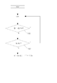
- FIG. 3 is a flowchart showing a flow of fuel injection amount correction control that is also the first embodiment.
- FIG. 6 is a flowchart showing a flow of fuel injection amount correction control that is also the second embodiment.
- FIG. 6 is a flowchart showing a flow of fuel injection amount abnormality detection control that is also Embodiment 3.
- FIG. 9 is a flowchart showing a flow of fuel injection amount correction control that is also the fourth embodiment.
- FIG. 9 is a flowchart showing a flow of fuel injection amount correction control that is also Embodiment 5.
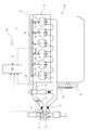
- the engine 1 includes an engine body 5 having a turbocharger 7 as a supercharger, an engine control unit (hereinafter referred to as ECU) 20 as a control means, an engine speed sensor 21 as an engine speed detection means, A turbo sensor 22 as a machine rotation speed detection means and a boost sensor 23 as a boost pressure detection means are provided.
- ECU engine control unit
- the engine body 5 includes a cylinder head 15 and a cylinder block 16.
- an intake pipe 8 is connected to an intake manifold (not shown), and an exhaust pipe 9 is connected to an exhaust manifold (not shown).
- an exhaust pipe 9 is connected to an exhaust manifold (not shown).
- the crankshaft 3 is pivotally supported by the cylinder block 16.
- the turbocharger 7 is composed of a turbine disposed in the exhaust pipe 9 and a compressor disposed in the intake pipe 8.
- the fuel injection device includes a common rail 10 and injectors 11.
- the common rail 10 is a pressure vessel that accumulates fuel sent by a fuel injection pump (not shown).
- the injector 11 is a device that injects fuel accumulated in the common rail 10 into each cylinder.
- the ECU 20 is connected with an engine speed sensor 21, a turbo sensor 22, a boost sensor 23, an accelerator opening sensor 24, and injectors 11. Note that the throttle lever opening sensor may be used instead of the accelerator opening sensor 24.
- the engine speed sensor 21 is provided in the vicinity of the crankshaft 3 and detects the engine speed Ne.
- the turbo sensor 22 is provided on the compressor 6 side of the turbocharger 7, generates a rotation pulse according to the number of blades of the compressor 6, and detects the turbocharger rotation speed (turbo rotation speed) Nc.
- the turbo sensor 22 is, for example, an eddy current type or a hall sensor. Further, the turbo rotation speed Nc may be a value divided by a predetermined ratio in order to reduce the calculation burden on the ECU 20.
- the boost sensor 23 is provided in the intake pipe 8 and detects a supercharging pressure (boost pressure) Pb.
- the accelerator opening sensor 24 is provided at the accelerator rotation base, and detects the accelerator opening Ac.
- the ECU 20 has a function of calculating the fuel injection amount Q from the fuel injection amount map f3q (Ne, Ac, Q) based on the engine speed Ne and the accelerator opening degree Ac.
- the fuel injection amount map f3q (Ne, Ac, Q) is a three-dimensional map stored in advance in the storage device of the ECU 20.
- the ECU 20 has a function of calculating an appropriate turbo speed Nemap from an appropriate engine speed map f3e (Nmap, Nc, Q) based on the turbo speed Nc and the fuel injection amount Q.
- the appropriate engine speed map f3e (Nmap, Nc, Q) is a three-dimensional map representing the correlation between the turbo speed, the appropriate engine speed Nemap, and the fuel injection amount Q, and is stored in advance in the storage device of the ECU 20. ing.
- the ECU 20 has a function of calculating an appropriate turbo speed Ncmap from an appropriate turbo speed map f3c (Ne, Ncmap, Q) based on the engine speed Ne and the fuel injection amount Q.
- the appropriate turbo speed map f3c (Ne, Ncmap, Q) is a three-dimensional map showing the correlation between the engine speed Ne, the appropriate turbo speed Ncmap, and the fuel injection amount Q, and is stored in advance in the storage device of the ECU 20. Has been.
- the ECU 20 acquires each physical quantity necessary for this control. That is, the ECU 20 acquires the engine speed Ne by the engine speed sensor 21, the turbo speed Nc by the turbo sensor 22, and the accelerator opening Ac by the accelerator opening sensor 24. Further, the ECU 20 calculates the fuel injection amount Q from the fuel injection amount map f3q (Ne, Ac) based on the engine speed Ne and the accelerator opening degree Ac.
- the ECU 20 calculates an appropriate turbo speed Ncmap as an appropriate turbo speed from the appropriate turbo speed map f3c (Ne, Ncmap, Q) based on the engine speed Ne and the fuel injection amount Q, A threshold value ⁇ ⁇ Nc allowed for the appropriate turbo rotation speed Ncmap is calculated.
- the threshold value ⁇ ⁇ Nc is determined for each appropriate turbo rotation speed Ncmap value, and is different depending on the engine rotation speed Ne and the fuel injection amount Q.
- the ECU 20 calculates the appropriate engine speed Nemap from the appropriate engine speed map f3e (Nmap, Nc, Q) based on the turbo speed Nc and the fuel injection amount Q, and sets the appropriate engine speed Nemap.
- An allowable threshold value ⁇ ⁇ Ne is calculated. The threshold value ⁇ ⁇ Ne is determined for each appropriate engine speed Nemap value, and is different depending on the turbo speed Nc and the fuel injection amount Q.
- the ECU 20 determines whether the absolute value of the difference between the turbo rotational speed Nc and the appropriate turbo rotational speed Ncmap is smaller than the threshold value ⁇ Nc.
- the ECU 20 determines whether or not the absolute value of the difference between the engine speed Ne and the appropriate engine speed Nemap is smaller than the threshold value ⁇ Ne. If No in S114, the ECU 20 returns to S111.
- the ECU 20 determines the fuel injection amount Q in the appropriate turbo speed map f3c (Ne, Ncmap, Q) and the appropriate engine speed map f3e (Nmap, Nc, Q) in S115. To the current fuel injection amount Q.
- ECU20 acquires each physical quantity required in this control. That is, the ECU 20 acquires the engine speed Ne, the turbo speed Nc, and the accelerator opening degree Ac. Further, the ECU 20 calculates the fuel injection amount Q from the fuel injection amount map f3q (Ne, Ac, Q) based on the engine speed Ne and the accelerator opening degree Ac. Further, the ECU 20 calculates an appropriate turbo speed Ncmap from the appropriate turbo speed map f3c (Ne, Ncmap, Q) based on the engine speed Ne and the fuel injection amount Q.
- the ECU 20 calculates an allowable increase / decrease amount ⁇ ⁇ Q of the fuel injection amount Q.
- the threshold value ⁇ ⁇ Q is determined for each fuel injection amount Q, and is different depending on the engine speed Ne and the turbo speed Nc. Further, the ECU 20 calculates a turbo speed upper limit value Ncl determined by the engine speed Ne.
- the ECU 20 determines whether the difference between the corrected fuel injection amount Q ′ and the fuel injection amount Q is within a threshold value ⁇ ⁇ Q. If Yes in S122, the process returns to S121.
- the difference between the corrected fuel injection amount Q ′ and the fuel injection amount Q is within the appropriate fuel injection amount correction range, it is possible to prevent the corrected fuel injection amount Q ′ from being excessive or insufficient. Further, since the difference between the fuel injection amount Q ′ corrected based on the turbo rotation speed Nc and the fuel injection amount Q is limited, it is possible to prevent the corrected fuel injection amount Q ′ from becoming excessive.
- the ECU 20 stops increasing the fuel injection amount Q if the turbo rotational speed Nc is larger than the turbo rotational speed upper limit value Ncl.
- the ECU 20 determines whether the fuel injection abnormality determination counter value N is N ⁇ 5. If Yes in S136, the process returns to S131.
- the ECU 20 determines that the engine has failed in the case of No in S136. After the engine failure is confirmed, derating control is performed to decelerate in steps and stop the engine 1.
- the ECU 20 has a function of calculating the appropriate engine speed Nemap from the appropriate engine speed map f4e (Nmap, Nc, Pb, Q) based on the turbo speed Nc, the boost pressure Pb, and the fuel injection amount Q.
- the appropriate engine speed map f4e (Nmap, Nc, Pb, Q) is a four-dimensional map representing the correlation among the appropriate engine speed Nemap, the boost pressure Pb, the turbo speed Nc, and the fuel injection amount Q. Is stored in advance in the storage device.
- the ECU 20 has a function of calculating an appropriate turbo speed Ncmap from an appropriate turbo speed map f4c (Ne, Ncmap, Pb, Q) based on the engine speed Ne, the boost pressure Pb, and the fuel injection amount Q.
- the appropriate turbo speed map f4c (Ne, Ncmap, Pb, Q) is a four-dimensional map representing the correlation among the engine speed Ne, the boost pressure Pb, the appropriate turbo speed Ncmap, and the fuel injection amount Q. Is stored in advance in the storage device.
- the ECU 20 has a function of calculating the appropriate boost pressure Pbmap from the appropriate boost pressure map f4p (Ne, Nc, Pbmap, Q) based on the engine speed Ne, the turbo speed Nc, and the fuel injection amount Q.
- the appropriate boost pressure map f4p (Ne, Nc, Pbmap, Q) is a four-dimensional map showing the correlation among the engine speed Ne, the appropriate boost pressure Pbmap, the turbo speed Nc, and the fuel injection amount Q. Pre-stored in the storage device.
- the ECU 20 acquires each physical quantity necessary for this control. That is, the ECU 20 acquires the engine speed Ne, the turbo speed Nc, the boost pressure Pb, and the accelerator opening degree Ac. Further, the ECU 20 calculates the fuel injection amount Q from the fuel injection amount map f3q (Ne, Ac, Q) based on the engine speed Ne and the accelerator opening degree Ac.
- the ECU 20 calculates an appropriate turbo speed Ncmap from the appropriate turbo speed map f4c (Ne, Ncmap, Pb, Q) based on the engine speed Ne, the fuel injection amount Q, and the boost pressure Pb. Then, an allowable threshold value ⁇ ⁇ Nc of the appropriate turbo rotation speed Ncmap is calculated. The threshold value ⁇ ⁇ Nc is determined for each appropriate turbo speed Ncmap, and is different depending on the engine speed Ne, the boost pressure Pb, and the fuel injection amount Q. Further, the ECU 20 calculates an allowable threshold value ⁇ ⁇ Pb of the appropriate boost pressure Pbmap. The threshold value ⁇ ⁇ Pb is determined for each appropriate boost pressure Pbmap, and is different depending on the engine speed Ne, the turbo speed Nc, and the fuel injection amount Q.
- the ECU 20 determines whether the absolute value of the difference between the turbo speed Nc and the appropriate turbo speed Ncmap is smaller than the threshold value ⁇ Nc, and whether the absolute value of the difference between the boost pressure Pb and the appropriate boost pressure Pbmap is smaller than the threshold value ⁇ Pb. Determine.
- the ECU 20 performs the following processing. That is, if the difference between the turbo rotation speed Nc and the appropriate turbo rotation speed Ncmap is smaller than 0 and the difference between the boost pressure Pb and the appropriate boost pressure Pbmap is smaller than 0, the ECU 20 determines that the turbo rotation speed Nc is the appropriate turbo rotation.
- the fuel injection amount Q is increased until it becomes larger than the sum of several Ncmap and the threshold value ⁇ Nc.
- the ECU 20 determines whether the absolute value of the difference between the engine speed Ne and the appropriate engine speed Nemap is smaller than the threshold value ⁇ Ne. If No, the ECU 20 returns to S141.
- the ECU 20 determines in S146 that the appropriate engine speed map f4e (Nmap, Nc, Pb, Q), the appropriate turbo speed map f4c (Ne, Ncmap, Pb, Q), and the appropriate The value of the fuel injection amount Q in the boost pressure map f4p (Ne, Nc, Pbmap, Q) is rewritten to the current fuel injection amount Q.
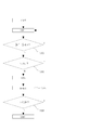
- the fuel injection amount correction control according to the fifth embodiment will be described with reference to FIG.
- the ECU 20 has a function of calculating an engine speed increase / decrease rate TNe, which is an increase / decrease rate of the engine speed Ne during a predetermined time. Further, the ECU 20 has a function of calculating a turbo rotation speed increase / decrease rate TNc, which is an increase / decrease rate of the turbo rotation speed Nc in a predetermined time. Further, the ECU 20 has a function of calculating a boost pressure increase / decrease rate TPb that is an increase / decrease rate of the boost pressure Pb in a predetermined time.
- the ECU 20 includes a fuel injection amount increase / decrease rate map fT3q (TNe, Ac, TQ).
- the fuel injection amount increase / decrease rate map f3Tq (TNe, Ac, TQ) is a three-dimensional map showing the correlation among the engine speed increase / decrease rate TNe, the accelerator opening degree Ac, and the fuel injection amount increase / decrease rate TQ.
- the fuel injection amount increase / decrease rate TQ is determined to be a single value if the engine speed increase / decrease rate TNe and the accelerator opening degree Ac are determined by the fuel injection amount increase / decrease rate map fT3q (TNe, Ac).
- the ECU 20 uses the appropriate engine speed increase / decrease rate map f4Te (TNMap, TNc, TPb, TQ) to increase / decrease the appropriate engine speed. It has a function to calculate the rate TNMap.
- the appropriate engine speed increase / decrease rate map f4Te (TNMap, TNc, TPb, TQ) is a correlation between the appropriate engine speed increase / decrease rate TNe, the boost pressure increase / decrease rate TPb, the turbo speed increase / decrease rate TNc, and the fuel injection amount increase / decrease rate TQ. Is stored in advance in a storage device of the ECU 20.
- the ECU 20 uses the appropriate turbo speed map f4c (TNe, TNcmap, TPb, TQ) to determine the appropriate turbo speed increase / decrease rate TNcmap. It has the function to calculate.
- the appropriate turbo speed map f4c (TNe, TNcmap, TPb, TQ) represents the correlation between the engine speed increase / decrease rate TNe, the boost pressure increase / decrease rate TPb, the appropriate turbo speed increase / decrease rate TNcmap, and the fuel injection amount increase / decrease rate TQ. It is a four-dimensional map and is stored in advance in the storage device of the ECU 20.
- the ECU 20 increases or decreases the appropriate boost pressure based on the appropriate boost pressure increase / decrease rate map f4Tp (TNe, TNc, TPbmap, TQ) based on the engine speed increase / decrease rate TNe, the turbo speed increase / decrease rate TNc, and the fuel injection amount increase / decrease rate TQ. It has a function of calculating the rate TPbmap.
- the appropriate boost pressure increase / decrease rate map f4Tp (TNe, TNc, TPbmap, TQ) is a correlation between the engine speed increase / decrease rate TNe, the appropriate boost pressure increase / decrease rate TPbmap, the turbo speed increase / decrease rate TNcmap, and the fuel injection amount increase / decrease rate TQ. This is a four-dimensional map that is stored in advance in the storage device of the ECU 20.
- the ECU 20 acquires an increase / decrease rate of each physical quantity. That is, the ECU 20 calculates the engine speed increase / decrease rate TNe, the turbo speed increase / decrease rate RNc, and the boost pressure increase / decrease rate RPb. Further, the ECU 20 acquires the accelerator opening degree Ac by the accelerator opening degree sensor 24. Further, the ECU 20 calculates the fuel injection amount increase / decrease rate TQ from the fuel injection amount increase / decrease rate map f3Tq (TNe, Ac, TQ) based on the engine speed increase / decrease rate TNe and the accelerator opening degree Ac.
- the ECU 20 determines from the appropriate engine speed increase / decrease rate map f4Te (TNMap, TNc, TPb, TQ) based on the turbo speed increase / decrease rate TNc, the boost pressure increase / decrease rate TPb, and the fuel injection amount increase / decrease rate TQ.
- An appropriate engine speed increase / decrease rate TNMap is calculated.
- the ECU 20 calculates an allowable threshold value ⁇ ⁇ TNe for the appropriate engine speed increase / decrease rate TNnemap.
- the threshold value ⁇ ⁇ TNe is determined for each appropriate engine speed increase / decrease rate TNmap value, and is different depending on the turbo speed increase / decrease rate TNc, the boost pressure increase / decrease rate TPb, and the fuel injection amount increase / decrease rate TQ.
- the ECU 20 determines from the appropriate turbo speed increase / decrease rate map f4Tc (TNe, TNcmap, TPb, TQ) based on the engine speed increase / decrease rate TNe, the boost pressure increase / decrease rate TPb, and the fuel injection amount increase / decrease rate TQ.
- An appropriate turbo rotational speed increase / decrease rate TNcmap is calculated, and an allowable threshold value ⁇ ⁇ TNc of the appropriate turbo rotational speed increase / decrease rate TNcmap is calculated.
- the threshold value ⁇ ⁇ TNc is determined for each appropriate turbo rotational speed increase / decrease rate TNcmap, and is different depending on the engine rotational speed increase / decrease rate TNe, the boost pressure increase / decrease rate TPb, and the fuel injection amount increase / decrease rate TQ.
- the ECU 20 determines from the appropriate boost pressure increase / decrease rate map f4Tp (TNe, TNc, TPbmap, TQ) based on the engine speed increase / decrease rate TNe, the turbo speed increase / decrease rate TNc, and the fuel injection amount increase / decrease rate TQ.
- An appropriate turbo rotational speed increase / decrease rate TPbmap is calculated, and an allowable threshold value ⁇ ⁇ TPb of the appropriate boost pressure increase / decrease rate TPbmap is calculated.
- the threshold value ⁇ ⁇ TPb is determined for each appropriate turbo rotation speed increase / decrease rate TPbmap, and is different depending on the engine speed increase / decrease rate TNe, the turbo speed increase / decrease rate TNc, and the fuel injection amount increase / decrease rate TQ.
- the ECU 20 determines that the absolute value of the difference between the turbo rotational speed increase / decrease rate TNc and the appropriate turbo rotational speed increase / decrease rate TNcmap is smaller than the threshold ⁇ TNc, and the difference between the boost pressure increase / decrease rate Pba and the appropriate boost pressure increase / decrease rate TPbmap. It is determined whether the absolute value is smaller than the threshold value ⁇ TPb.
- the ECU 20 performs the following control in the case of No in S152. That is, if the difference between the turbo speed increase / decrease rate TNc and the appropriate turbo speed increase / decrease rate TNcmap is smaller than 0 and the difference between the boost pressure increase / decrease rate TPb and the appropriate boost pressure increase / decrease rate TPbmap is smaller than 0,
- the injection characteristic feedback control is performed so that the turbo rotational speed increase / decrease rate TNc is larger than the sum of the appropriate turbo rotational speed increase / decrease rate TNcmap and the threshold value ⁇ TNc.
- the ECU 20 determines that the turbo rotation speed increases if the turbo rotation speed increase / decrease rate TNc is greater than the appropriate turbo rotation speed increase / decrease rate TNcmap and the difference between the boost pressure increase / decrease rate TPb and the appropriate boost pressure increase / decrease rate TPbmap is greater than 0.
- the injection characteristic feedback control is performed so that the number increase / decrease rate TNca is smaller than the difference between the appropriate turbo rotation speed increase / decrease rate TNcmap and the threshold value ⁇ TNc.
- the ECU 20 returns to S151 after completing the above-described processing.
- the ECU 20 determines whether the absolute value of the difference between the engine speed increase / decrease rate TNe and the appropriate engine speed increase / decrease rate TNMap is smaller than the threshold value ⁇ TNe. If No, the ECU 20 returns to S151.
- the ECU 20 determines that the appropriate turbo speed increase / decrease rate map f4Tc (TNcmap, TNe, TPb, TQ), the appropriate boost increase / decrease rate map f4Tp (TNe, TNc, TPbmap, TQ), and the appropriate engine.
- the value of the fuel injection amount TQ in the rotation speed increase / decrease rate map f4Te (TNMap, TNc, TPb, TQ) is rewritten to the current fuel injection amount increase / decrease rate TQ.
- the variation in the fuel injection amount in the acceleration / deceleration operation state of the engine 1 based on the turbo speed increase / decrease rate TNc, the boost pressure increase / decrease rate TPb, and the engine speed increase / decrease rate TNe Can be corrected. Further, since the turbo speed increase / decrease rate TNc, the boost increase / decrease rate TPb, and the engine speed increase / decrease rate TNe are rewritten, the fuel injection amount correction corresponding to the secular change of the fuel injection device can be performed.
- the present invention can be used for an engine.
Landscapes
- Engineering & Computer Science (AREA)
- Chemical & Material Sciences (AREA)
- Combustion & Propulsion (AREA)
- Mechanical Engineering (AREA)
- General Engineering & Computer Science (AREA)
- Output Control And Ontrol Of Special Type Engine (AREA)
- Electrical Control Of Air Or Fuel Supplied To Internal-Combustion Engine (AREA)
- Supercharger (AREA)
Priority Applications (5)
| Application Number | Priority Date | Filing Date | Title |
|---|---|---|---|
| CN200980108778.1A CN101970838B (zh) | 2008-03-13 | 2009-03-02 | 发动机 |
| US12/921,746 US8423266B2 (en) | 2008-03-13 | 2009-03-02 | Engine |
| BRPI0909626A BRPI0909626A2 (pt) | 2008-03-13 | 2009-03-02 | motor |
| EP09719598.6A EP2282035A4 (de) | 2008-03-13 | 2009-03-02 | Motor |
| CA2716569A CA2716569C (en) | 2008-03-13 | 2009-03-02 | Engine |
Applications Claiming Priority (2)
| Application Number | Priority Date | Filing Date | Title |
|---|---|---|---|
| JP2008-064574 | 2008-03-13 | ||
| JP2008064574A JP2009221881A (ja) | 2008-03-13 | 2008-03-13 | エンジン |
Publications (1)
| Publication Number | Publication Date |
|---|---|
| WO2009113421A1 true WO2009113421A1 (ja) | 2009-09-17 |
Family
ID=41065089
Family Applications (1)
| Application Number | Title | Priority Date | Filing Date |
|---|---|---|---|
| PCT/JP2009/053880 WO2009113421A1 (ja) | 2008-03-13 | 2009-03-02 | エンジン |
Country Status (8)
| Country | Link |
|---|---|
| US (1) | US8423266B2 (de) |
| EP (1) | EP2282035A4 (de) |
| JP (1) | JP2009221881A (de) |
| CN (1) | CN101970838B (de) |
| BR (1) | BRPI0909626A2 (de) |
| CA (1) | CA2716569C (de) |
| RU (1) | RU2451808C1 (de) |
| WO (1) | WO2009113421A1 (de) |
Families Citing this family (8)
| Publication number | Priority date | Publication date | Assignee | Title |
|---|---|---|---|---|
| JP4859718B2 (ja) * | 2007-03-15 | 2012-01-25 | 本田技研工業株式会社 | ターボ過給機の異常判定装置 |
| DE112013000519T5 (de) * | 2012-01-31 | 2014-10-02 | Cummins Emission Solutions Inc. | Sensoren und Sensorschnittstellensysteme |
| JP2013194682A (ja) * | 2012-03-22 | 2013-09-30 | Yanmar Co Ltd | 多気筒エンジン |
| JP2013234591A (ja) * | 2012-05-08 | 2013-11-21 | Yanmar Co Ltd | エンジン |
| JP6163914B2 (ja) * | 2013-06-27 | 2017-07-19 | いすゞ自動車株式会社 | ディーゼルエンジン及びその制御方法 |
| JP6326910B2 (ja) | 2014-03-28 | 2018-05-23 | マツダ株式会社 | ターボ過給器付きエンジンの制御装置 |
| JP2016089708A (ja) * | 2014-11-04 | 2016-05-23 | ヤンマー株式会社 | エンジン |
| JP7230715B2 (ja) * | 2019-07-09 | 2023-03-01 | トヨタ自動車株式会社 | ハイブリッド車両の制御装置 |
Citations (7)
| Publication number | Priority date | Publication date | Assignee | Title |
|---|---|---|---|---|
| JPH1193747A (ja) * | 1997-09-17 | 1999-04-06 | Toyota Motor Corp | 内燃機関におけるアイドル回転数制御装置 |
| JPH11324777A (ja) * | 1998-05-15 | 1999-11-26 | Denso Corp | 過給機付内燃機関の燃料噴射装置 |
| JP2000328999A (ja) | 1999-05-21 | 2000-11-28 | Horiba Ltd | 走行車両における軸平均有効圧簡易測定方法 |
| JP2005220761A (ja) * | 2004-02-03 | 2005-08-18 | Denso Corp | ディーゼル機関の制御装置 |
| JP2007263127A (ja) * | 2007-07-23 | 2007-10-11 | Hitachi Ltd | エンジンの燃料制御装置,エンジンの燃料制御方法 |
| JP2007303382A (ja) * | 2006-05-11 | 2007-11-22 | Yanmar Co Ltd | エンジンのトルク検知手段 |
| JP2007332793A (ja) * | 2006-06-12 | 2007-12-27 | Yanmar Co Ltd | 過給器を備えるエンジン |
Family Cites Families (35)
| Publication number | Priority date | Publication date | Assignee | Title |
|---|---|---|---|---|
| SU1332052A1 (ru) * | 1985-08-02 | 1987-08-23 | Харьковский политехнический институт им.В.И.Ленина | Электронный регул тор частоты вращени дизель-генератора с турбокомпрессором |
| JPS6275087A (ja) | 1985-09-26 | 1987-04-06 | Tokico Ltd | 耐溶媒性ベ−ンポンプ翼弁用組成物 |
| SU1348549A1 (ru) * | 1986-02-10 | 1987-10-30 | Ленинградский институт инженеров железнодорожного транспорта им.акад.В.Н.Образцова | Система регулировани подачи топлива транспортного дизел |
| JPH0511316Y2 (de) * | 1987-05-18 | 1993-03-19 | ||
| JPH05248301A (ja) * | 1992-03-04 | 1993-09-24 | Toyota Motor Corp | ディーゼルエンジンのファーストアイドル制御装置 |
| DE19541774A1 (de) * | 1995-11-09 | 1997-05-15 | Bosch Gmbh Robert | Verfahren und Vorrichtung zur Erkennung eines Lecks in einem Kraftstoffversorgungssystem einer Brennkraftmaschine mit Hochdruckeinspritzung |
| US5724949A (en) * | 1996-11-06 | 1998-03-10 | Caterpillar Inc. | Hydraulic drive for a pressure wave supercharger utilized with an internal combustion engine |
| US5987888A (en) * | 1997-07-15 | 1999-11-23 | Detroit Diesel Corporation | System and method for controlling a turbocharger |
| DE19751977C2 (de) * | 1997-11-25 | 2001-02-01 | Daimler Chrysler Ag | Steuerung für den Ladedruck einer aufgeladenen Brennkraftmaschine |
| JP3588999B2 (ja) * | 1997-12-15 | 2004-11-17 | 日産自動車株式会社 | ディーゼルエンジンの冷間・暖機中の制御装置 |
| JP3680528B2 (ja) * | 1997-12-19 | 2005-08-10 | 日産自動車株式会社 | エンジンのアイドル回転学習制御装置 |
| US6944532B2 (en) * | 1998-06-18 | 2005-09-13 | Cummins, Inc. | System for controlling an internal combustion engine in a fuel efficient manner |
| JP4024423B2 (ja) * | 1999-03-31 | 2007-12-19 | 日産ディーゼル工業株式会社 | ターボチャージャ付内燃機関の燃料噴射量制御装置 |
| RU2191912C2 (ru) * | 1999-10-18 | 2002-10-27 | ОАО Ярославский завод дизельной аппаратуры | Система управления топливоподачей с помощью электромагнитных клапанов |
| US6360541B2 (en) * | 2000-03-03 | 2002-03-26 | Honeywell International, Inc. | Intelligent electric actuator for control of a turbocharger with an integrated exhaust gas recirculation valve |
| ITTO20010041A1 (it) * | 2001-01-19 | 2002-07-19 | Iveco Motorenforschung Ag | Sistema di controllo per turbocompressore a geometria variabile. |
| JP4082486B2 (ja) * | 2002-01-22 | 2008-04-30 | 富士重工業株式会社 | 電子制御スロットル式エンジンの制御装置 |
| US6665604B2 (en) * | 2002-02-05 | 2003-12-16 | Honeywell International Inc. | Control method for variable geometry turbocharger and related system |
| US6681573B2 (en) * | 2002-02-05 | 2004-01-27 | Honeywell International Inc | Methods and systems for variable geometry turbocharger control |
| US6698203B2 (en) * | 2002-03-19 | 2004-03-02 | Cummins, Inc. | System for estimating absolute boost pressure in a turbocharged internal combustion engine |
| EP1363008B1 (de) * | 2002-05-14 | 2007-01-10 | Robert Bosch Gmbh | Verfahren und Vorrichtung zur Steuerung der einzuspritzenden Kraftstoffmenge einer selbstzündenden Brennkraftmaschine |
| JP2004060479A (ja) * | 2002-07-26 | 2004-02-26 | Hitachi Ltd | エンジンの燃料制御装置,エンジンの燃料制御方法 |
| US6725659B1 (en) * | 2002-12-16 | 2004-04-27 | Cummins, Inc. | Apparatus and method for limiting turbocharger speed |
| KR100559423B1 (ko) * | 2003-11-07 | 2006-03-10 | 현대자동차주식회사 | 연료 분사시기 제어 방법 및 시스템 |
| KR100787484B1 (ko) * | 2004-04-02 | 2007-12-21 | 가부시키가이샤 고마쓰 세이사쿠쇼 | 내연기관의 배기가스 정화장치 |
| US7165403B2 (en) * | 2004-07-28 | 2007-01-23 | Ford Global Technologies, Llc | Series/parallel turbochargers and switchable high/low pressure EGR for internal combustion engines |
| JP4453538B2 (ja) * | 2004-12-16 | 2010-04-21 | トヨタ自動車株式会社 | 内燃機関の燃料噴射制御装置 |
| US7591135B2 (en) * | 2004-12-29 | 2009-09-22 | Honeywell International Inc. | Method and system for using a measure of fueling rate in the air side control of an engine |
| KR100749620B1 (ko) * | 2005-03-02 | 2007-08-14 | 가부시키가이샤 덴소 | 과급기 부착 내연 기관용 제어 장치 |
| US8484968B2 (en) * | 2005-03-31 | 2013-07-16 | General Electric Company | System and method for operating a compression-ignition engine |
| US7246005B2 (en) * | 2005-06-07 | 2007-07-17 | Arvin Technologies, Inc. | Method and apparatus for controlling a component by feed-forward closed-loop controller state modification |
| US8307645B2 (en) * | 2005-11-02 | 2012-11-13 | General Electric Company | Apparatus and method for avoidance of turbocharger surge on locomotive diesel engines |
| JP2007231821A (ja) * | 2006-03-01 | 2007-09-13 | Toyota Motor Corp | 過給器を備える内燃機関の制御 |
| JP4539991B2 (ja) * | 2006-06-02 | 2010-09-08 | ヤンマー株式会社 | セタン価検出手段及び該セタン価検出手段を設けるエンジン |
| US7721539B2 (en) * | 2007-05-01 | 2010-05-25 | Cummins Inc. | System for controlling engine fueling to limit engine output power |
-
2008
- 2008-03-13 JP JP2008064574A patent/JP2009221881A/ja active Pending
-
2009
- 2009-03-02 US US12/921,746 patent/US8423266B2/en active Active
- 2009-03-02 WO PCT/JP2009/053880 patent/WO2009113421A1/ja active Application Filing
- 2009-03-02 RU RU2010141831/06A patent/RU2451808C1/ru not_active IP Right Cessation
- 2009-03-02 CA CA2716569A patent/CA2716569C/en not_active Expired - Fee Related
- 2009-03-02 CN CN200980108778.1A patent/CN101970838B/zh not_active Expired - Fee Related
- 2009-03-02 EP EP09719598.6A patent/EP2282035A4/de not_active Withdrawn
- 2009-03-02 BR BRPI0909626A patent/BRPI0909626A2/pt not_active IP Right Cessation
Patent Citations (7)
| Publication number | Priority date | Publication date | Assignee | Title |
|---|---|---|---|---|
| JPH1193747A (ja) * | 1997-09-17 | 1999-04-06 | Toyota Motor Corp | 内燃機関におけるアイドル回転数制御装置 |
| JPH11324777A (ja) * | 1998-05-15 | 1999-11-26 | Denso Corp | 過給機付内燃機関の燃料噴射装置 |
| JP2000328999A (ja) | 1999-05-21 | 2000-11-28 | Horiba Ltd | 走行車両における軸平均有効圧簡易測定方法 |
| JP2005220761A (ja) * | 2004-02-03 | 2005-08-18 | Denso Corp | ディーゼル機関の制御装置 |
| JP2007303382A (ja) * | 2006-05-11 | 2007-11-22 | Yanmar Co Ltd | エンジンのトルク検知手段 |
| JP2007332793A (ja) * | 2006-06-12 | 2007-12-27 | Yanmar Co Ltd | 過給器を備えるエンジン |
| JP2007263127A (ja) * | 2007-07-23 | 2007-10-11 | Hitachi Ltd | エンジンの燃料制御装置,エンジンの燃料制御方法 |
Non-Patent Citations (1)
| Title |
|---|
| See also references of EP2282035A4 |
Also Published As
| Publication number | Publication date |
|---|---|
| BRPI0909626A2 (pt) | 2018-04-10 |
| CA2716569C (en) | 2012-08-07 |
| US20110023828A1 (en) | 2011-02-03 |
| JP2009221881A (ja) | 2009-10-01 |
| EP2282035A4 (de) | 2015-12-16 |
| CA2716569A1 (en) | 2009-09-17 |
| EP2282035A1 (de) | 2011-02-09 |
| US8423266B2 (en) | 2013-04-16 |
| CN101970838B (zh) | 2014-07-09 |
| RU2010141831A (ru) | 2012-04-20 |
| CN101970838A (zh) | 2011-02-09 |
| RU2451808C1 (ru) | 2012-05-27 |
Similar Documents
| Publication | Publication Date | Title |
|---|---|---|
| WO2009113421A1 (ja) | エンジン | |
| US7509210B2 (en) | Abnormality determination apparatus and method for blow-by gas feedback device, and engine control unit | |
| US7051725B2 (en) | Cylinder-by-cylinder air-fuel ratio calculation apparatus for multi-cylinder internal combustion engine | |
| JP4583038B2 (ja) | 過給機付き内燃機関の過給圧推定装置 | |
| US9062596B2 (en) | Wastegate valve control device for internal combustion engine and wastegate valve control method for internal combustion engine | |
| US7243532B2 (en) | Misfire detector for internal combustion engines | |
| WO2007141964A1 (ja) | セタン価検出手段及び該セタン価検出手段を設けるエンジン | |
| US9228515B2 (en) | Controller and control method for internal combustion engine | |
| US20110100326A1 (en) | Engine Control Unit | |
| WO2013129149A1 (ja) | エンジン | |
| US20110320105A1 (en) | Electronically Controlled Diesel Engine | |
| JP2010163950A (ja) | 内燃機関の制御装置 | |
| US5623905A (en) | Method and arrangement for controlling an internal combustion engine | |
| JP2011001822A (ja) | 電制スロットル特性学習制御装置及び方法 | |
| JP2007009877A (ja) | 過給圧制御システムの異常診断装置 | |
| JP2007303294A (ja) | 過給機付き内燃機関の制御装置 | |
| US10982628B2 (en) | Controller for internal combustion engine and control method for internal combustion engine | |
| JP5294527B2 (ja) | 内燃機関の動作のための方法、コンピュータプログラム及び開ループ及び/又は閉ループ制御装置 | |
| JP2010048125A (ja) | 内燃機関のセンサ故障判定装置 | |
| JP5640776B2 (ja) | 燃料噴射制御装置 | |
| JP2004019539A (ja) | 内燃機関用燃料噴射制御装置 | |
| JP2006009674A (ja) | 内燃機関の制御装置 | |
| JP2006328970A (ja) | スワール制御系の異常判定装置 | |
| JP2008069693A (ja) | 内燃機関の故障診断システム | |
| JP6367045B2 (ja) | 燃料噴射制御装置及び燃料噴射制御方法 |
Legal Events
| Date | Code | Title | Description |
|---|---|---|---|
| WWE | Wipo information: entry into national phase |
Ref document number: 200980108778.1 Country of ref document: CN |
|
| 121 | Ep: the epo has been informed by wipo that ep was designated in this application |
Ref document number: 09719598 Country of ref document: EP Kind code of ref document: A1 |
|
| WWE | Wipo information: entry into national phase |
Ref document number: 2716569 Country of ref document: CA |
|
| REEP | Request for entry into the european phase |
Ref document number: 2009719598 Country of ref document: EP |
|
| WWE | Wipo information: entry into national phase |
Ref document number: 2009719598 Country of ref document: EP |
|
| WWE | Wipo information: entry into national phase |
Ref document number: 6191/DELNP/2010 Country of ref document: IN |
|
| WWE | Wipo information: entry into national phase |
Ref document number: 12921746 Country of ref document: US |
|
| NENP | Non-entry into the national phase |
Ref country code: DE |
|
| WWE | Wipo information: entry into national phase |
Ref document number: 2010141831 Country of ref document: RU |
|
| ENP | Entry into the national phase |
Ref document number: PI0909626 Country of ref document: BR Kind code of ref document: A2 Effective date: 20100910 |