WO2009104553A1 - 永久磁石式回転電機、永久磁石式回転電機の組立方法、永久磁石式回転電機の分解方法及び永久磁石電動機ドライブシステム - Google Patents
永久磁石式回転電機、永久磁石式回転電機の組立方法、永久磁石式回転電機の分解方法及び永久磁石電動機ドライブシステム Download PDFInfo
- Publication number
- WO2009104553A1 WO2009104553A1 PCT/JP2009/052536 JP2009052536W WO2009104553A1 WO 2009104553 A1 WO2009104553 A1 WO 2009104553A1 JP 2009052536 W JP2009052536 W JP 2009052536W WO 2009104553 A1 WO2009104553 A1 WO 2009104553A1
- Authority
- WO
- WIPO (PCT)
- Prior art keywords
- permanent magnet
- magnetic
- magnetic flux
- rotor
- current
- Prior art date
Links
Images


Classifications
-
- H—ELECTRICITY
- H02—GENERATION; CONVERSION OR DISTRIBUTION OF ELECTRIC POWER
- H02K—DYNAMO-ELECTRIC MACHINES
- H02K1/00—Details of the magnetic circuit
- H02K1/06—Details of the magnetic circuit characterised by the shape, form or construction
- H02K1/22—Rotating parts of the magnetic circuit
- H02K1/27—Rotor cores with permanent magnets
- H02K1/2706—Inner rotors
- H02K1/272—Inner rotors the magnetisation axis of the magnets being perpendicular to the rotor axis
- H02K1/274—Inner rotors the magnetisation axis of the magnets being perpendicular to the rotor axis the rotor consisting of two or more circumferentially positioned magnets
- H02K1/2753—Inner rotors the magnetisation axis of the magnets being perpendicular to the rotor axis the rotor consisting of two or more circumferentially positioned magnets the rotor consisting of magnets or groups of magnets arranged with alternating polarity
- H02K1/276—Magnets embedded in the magnetic core, e.g. interior permanent magnets [IPM]
- H02K1/2766—Magnets embedded in the magnetic core, e.g. interior permanent magnets [IPM] having a flux concentration effect
-
- H—ELECTRICITY
- H02—GENERATION; CONVERSION OR DISTRIBUTION OF ELECTRIC POWER
- H02P—CONTROL OR REGULATION OF ELECTRIC MOTORS, ELECTRIC GENERATORS OR DYNAMO-ELECTRIC CONVERTERS; CONTROLLING TRANSFORMERS, REACTORS OR CHOKE COILS
- H02P21/00—Arrangements or methods for the control of electric machines by vector control, e.g. by control of field orientation
- H02P21/06—Rotor flux based control involving the use of rotor position or rotor speed sensors
-
- H—ELECTRICITY
- H02—GENERATION; CONVERSION OR DISTRIBUTION OF ELECTRIC POWER
- H02P—CONTROL OR REGULATION OF ELECTRIC MOTORS, ELECTRIC GENERATORS OR DYNAMO-ELECTRIC CONVERTERS; CONTROLLING TRANSFORMERS, REACTORS OR CHOKE COILS
- H02P27/00—Arrangements or methods for the control of AC motors characterised by the kind of supply voltage
- H02P27/04—Arrangements or methods for the control of AC motors characterised by the kind of supply voltage using variable-frequency supply voltage, e.g. inverter or converter supply voltage
-
- H—ELECTRICITY
- H02—GENERATION; CONVERSION OR DISTRIBUTION OF ELECTRIC POWER
- H02K—DYNAMO-ELECTRIC MACHINES
- H02K1/00—Details of the magnetic circuit
- H02K1/02—Details of the magnetic circuit characterised by the magnetic material
-
- H—ELECTRICITY
- H02—GENERATION; CONVERSION OR DISTRIBUTION OF ELECTRIC POWER
- H02P—CONTROL OR REGULATION OF ELECTRIC MOTORS, ELECTRIC GENERATORS OR DYNAMO-ELECTRIC CONVERTERS; CONTROLLING TRANSFORMERS, REACTORS OR CHOKE COILS
- H02P21/00—Arrangements or methods for the control of electric machines by vector control, e.g. by control of field orientation
-
- H—ELECTRICITY
- H02—GENERATION; CONVERSION OR DISTRIBUTION OF ELECTRIC POWER
- H02P—CONTROL OR REGULATION OF ELECTRIC MOTORS, ELECTRIC GENERATORS OR DYNAMO-ELECTRIC CONVERTERS; CONTROLLING TRANSFORMERS, REACTORS OR CHOKE COILS
- H02P2207/00—Indexing scheme relating to controlling arrangements characterised by the type of motor
- H02P2207/05—Synchronous machines, e.g. with permanent magnets or DC excitation
Definitions
- the present invention relates to a permanent magnet type rotating electrical machine, a method for assembling a permanent magnet type rotating electrical machine, a method for disassembling a permanent magnet type rotating electrical machine, and a permanent magnet motor drive system.
- an embedded permanent magnet type rotating electric machine is suitable.
- FIG. 20 shows a four-pole rotor 1, in which four cavities are provided and a permanent magnet 4 is inserted into each of them.
- the permanent magnet 4 is magnetized in the direction perpendicular to the radial direction of the rotor 1 or the side (long side in FIG. 20) facing the air gap surface in the rectangle of the cross section of the permanent magnet 4.
- a NdFeB permanent magnet having a high coercive force is mainly applied so as not to be demagnetized by a load current.
- the rotor core 2 is formed by laminating electromagnetic steel plates punched out of cavities. Such a rotor 1 is accommodated in the stator 20.
- the stator 20 is configured by housing the armature winding 21 in a slot formed inside the stator core 22.
- the inner peripheral surface of the stator 20 and the outer peripheral surface of the rotor 1 are opposed to each other through an air gap 23.
- Non-Patent Document 1 Design and Control of Embedded Magnet Synchronous Motor”, Yoji Takeda et al., Ohm Corporation (Non-Patent Document 1), Japanese Patent Application Laid-Open No. 07-336919 (Patent Document 1). )It has been known. Further, as a rotating electric machine having excellent variable speed characteristics and high output, there is a permanent magnet type reluctance type electric motor. As known examples thereof, JP-A-11-27913 (Patent Document 2) and JP-A-11-136912 (Patent Document 3) are known. Further, as a rotating electrical machine that changes the magnetic force of an AlNiCo magnet by an AlNiCo magnet embedded permanent magnet motor, U.S. Pat. No. 3, pp. 79-84 (1985) (Non-Patent Document 2) is known.
- the amount of magnetic flux of the AlNiCo magnet is changed by a permanent magnet motor using an AlNiCo magnet and a ferrite magnet.
- the rotating electrical machine described in Patent Document 4 is a magnetic flux concentration type embedded permanent magnet motor, and an AlNiCo magnet is used as the permanent magnet.
- This rotating electrical machine is a modification of the rotating electrical machine described in Non-Patent Document 2, and similarly to the rotating electrical machine of Non-Patent Document 2, a magnetic field is applied to change the amount of magnetic flux of the AlNiCo magnet.
- the induced voltage by the permanent magnet increases in proportion to the rotational speed. Therefore, when variable speed operation is performed from low speed to high speed, the induced voltage (back electromotive voltage) by the permanent magnet becomes extremely high at high speed rotation.
- the induced voltage by the permanent magnet is applied to the electronic component of the inverter and exceeds its withstand voltage, the electronic component breaks down. For this reason, it is conceivable to perform a design in which the amount of magnetic flux of the permanent magnet is reduced so as to be equal to or lower than the withstand voltage, but in that case, the output and efficiency in the low speed region of the permanent magnet type rotating electrical machine are reduced.
- variable speed operation When performing variable speed operation close to constant output from low speed to high speed, the flux linkage of the permanent magnet is constant, so the rotating electrical machine voltage reaches the upper limit of the power supply voltage in the high-speed rotation range and the current required for output does not flow. . As a result, the output is greatly reduced in the high-speed rotation region, and further, variable speed operation cannot be performed over a wide range up to high-speed rotation.
- the total amount of interlinkage magnetic flux of the armature winding is composed of a magnetic flux caused by a d-axis current and a magnetic flux caused by a permanent magnet.
- a total flux linkage is reduced by generating a magnetic flux due to a negative d-axis current.
- the permanent magnet having a high coercive force changes the operating point of the magnetic characteristics (BH characteristics) within a reversible range. For this reason, the NdFeB magnet having a high coercive force is applied to the permanent magnet so as not to be irreversibly demagnetized by the demagnetizing field of the weak magnetic flux control.
- the linkage flux decreases due to the negative d-axis current flux, so the decrease in linkage flux creates a voltage margin relative to the upper voltage limit. And since the electric current which becomes a torque component can be increased, the output in a high speed region increases. Further, the rotational speed can be increased by the voltage margin, and the range of variable speed operation is expanded.
- Patent Document 5 discloses a stator provided with windings in connection with a permanent magnet type rotating electrical machine that enables variable speed operation in a wide range from low speed to high speed with high output and realizes improvement in efficiency and reliability.
- the low coercivity permanent magnet is magnetized with a magnetic field by current so that the total interlinkage magnetic flux by the low coercivity permanent magnet and high coercivity permanent magnet is reduced. And a technique for adjusting the total flux linkage is described.
- a brushless DC motor described in Japanese Patent Application Laid-Open No. 07-336980 (Patent Document 6) is also known as a permanent magnet type electric motor.
- the rotor core has a first magnet part having a small coercive force and a second magnet part having a large coercive force, and the magnetic flux of the magnetic poles of the rotor core is reduced by energizing the armature winding.
- a configuration in which only the magnetization direction of the first magnet portion having a small coercive force is reversed is made possible to reduce the magnetic flux without causing an inverse field current to flow through the armature winding during demagnetization.
- the type of magnet employed in the first magnet part and the second magnet part is unknown, and the magnetic characteristics cannot be specified because the numerical values are unknown from FIG.
- the first magnet portion having a small coercive force is a ferrite permanent magnet
- the second magnet portion having a large coercive force is seen as an NdFeB permanent magnet.
- the coercive force is small and the magnets are easily demagnetized. There are problems such as demagnetization due to the magnetic field due to the shaft torque current, large current required for demagnetization, and insufficient torque.
- the permanent magnet having a coercive force exceeding 300 kA / m when adopted as a permanent magnet, a large current needs to flow to demagnetize the permanent magnet, which increases the power supply. There is a problem that the surrounding members are saturated by the magnetic field generated by the demagnetizing current and the permanent magnet cannot be demagnetized.
- the residual magnetic flux density of the permanent magnet also has a problem that if the residual magnetic flux density is smaller than 0.6T as in the case of a ferrite permanent magnet, the change amount of the magnetic flux becomes small and the output change width becomes small. .
- Patent Document 1 Japanese Patent Application Laid-Open No. 07-336919
- Patent Document 2 Japanese Patent Application Laid-Open No. 11-27913
- Patent Document 3 Japanese Patent Application Laid-Open No. 11-136912
- Patent Document 4 US Pat.
- Patent Document 6 Japanese Patent Laid-Open No. 07-336980
- Non-patent Document 1 “Design and Control of Embedded Magnet Synchronous Motor”, Yoji Takeda et al., Ohm Corporation
- Non-patent Document 2 Weschta, “Schachung des Erregerfelds bei für dauermagneterregten Synchronmaschine ”, ETZ Archiv Vol.7, No3, 79-84 (1985)
- An object of the present invention is to provide a permanent magnet type rotating electrical machine and a permanent magnet motor drive system capable of increasing output, improving efficiency, improving reliability, improving manufacturability, reducing materials, and reducing rare materials.
- One feature of the present invention is that a rotor in which a first permanent magnet and a second permanent magnet having different magnetic properties are embedded symmetrically with respect to the center of rotation in a rotor core, and the rotor is A permanent magnet type rotating electric machine having a stator arranged so as to be surrounded by a magnetic gap and an armature winding formed on an inner peripheral portion of the stator facing the magnetic gap.
- the magnetic characteristics of the first permanent magnet in the rotor are such that the coercive force is 100 kA / m to 300 kA / m, the residual magnetic flux density is 0.6 T or more, and the hysteresis characteristic shifts from the reversible magnetization range to the irreversible magnetization range.
- the magnetic property of the second permanent magnet in the rotor is larger than the first permanent magnet, the coercive force is larger than the first permanent magnet, the residual magnetic flux density is 0.6 T or more, and In the first permanent magnet, The product of the coercive force and the magnetization direction thickness of the second permanent magnet is equal to or greater than the product of the magnetic field strength and the magnetization direction thickness at the operating point when no load is applied to the second permanent magnet.
- This is a permanent magnet type rotating electrical machine in which the amount of magnetic flux of the first permanent magnet can be irreversibly changed by magnetizing the first permanent magnet with a magnetic field generated by the current.
- Another feature of the present invention is a method of assembling a permanent magnet type rotating electrical machine having the above-described configuration, wherein when the rotor is inserted and assembled inside the stator, the magnetic flux generated by the first permanent magnet, This is a method of assembling a permanent magnet type rotating electrical machine that is assembled in a state in which the magnetic flux generated by the second permanent magnet is magnetized so as to be opposite to each other on the magnetic pole or magnetic gap surface.
- Another feature of the present invention is a method for disassembling a permanent magnet type rotating electrical machine having the above-described configuration, wherein when the rotor is extracted from the inside of the stator, the magnetic flux generated by the first permanent magnet, and the second
- This is a method for disassembling a permanent magnet type rotating electrical machine that is extracted in a state where the magnetic fluxes of the permanent magnets are magnetized so as to be opposite to each other on the magnetic poles or the magnetic gap surfaces.
- a permanent magnet motor using a permanent magnet an inverter for driving the permanent magnet motor, and a magnetizing means for passing a magnetizing current for controlling the magnetic flux of the permanent magnet
- the permanent magnet motor includes a rotor in which a first permanent magnet and a second permanent magnet having different magnetic characteristics are embedded in a rotor core symmetrically with respect to the center of rotation, and the rotor is magnetized around the rotor.
- a stator disposed so as to surround the air gap; and an armature winding formed on an inner peripheral portion of the stator facing the magnetic air gap, wherein the magnetizing means includes the permanent magnet motor.
- the first permanent magnet is magnetized at each magnetic pole by a magnetic field generated by flowing a d-axis current of the armature winding for a short time, and the amount of magnetic flux of the permanent magnet is irreversibly changed.
- the coercive force is 100 kA / m to 300 kA / m
- the residual magnetic flux density is 0.6 T or more
- the reversible magnetization range from the reversible magnetization range to the irreversible magnetization range is 0.6 T or more
- the magnetic characteristics of the second permanent magnet in the rotor are larger than the first permanent magnet
- the residual magnetic flux The density is 0.6 T or more
- the product of the coercive force and the magnetization direction thickness of the first permanent magnet is the strength and magnetization direction of the magnetic field at the operating point when the second permanent magnet is unloaded
- the first permanent magnet and the second permanent magnet forming the magnetic pole are arranged and magnetized so that their magnetic fluxes are added together, and the current of the armature winding is
- the first permanent magnet is magnetized by a magnetic field to irreversibly decrease the interlinkage magnetic flux by the permanent magnet, and the magnetic field generated by the current of the armature winding after the decrease is generated in the reverse direction.
- This is a permanent magnet motor drive system that irreversibly increases the amount of flux linkage by magnetizing a permanent magnet.
- variable speed operation is possible in a wide range from low speed to high speed.
- high torque in the low speed rotation range and high output in the medium / high speed rotation range improvement in efficiency, improvement in reliability.
- the assembly method and the disassembly method of the permanent magnet type rotating electrical machine of the present invention in the above permanent magnet type rotating electrical machine, when the rotor is inserted and assembled inside the stator, or the rotor is removed from the stator.
- the rotor on the stator side is assembled or disassembled with the magnetic flux generated by the first permanent magnet and the magnetic flux generated by the second permanent magnet magnetized so that they are opposite to each other on the magnetic pole or the magnetic gap surface.
- the above permanent magnet type rotating electrical machine is operated as a permanent magnet motor and is operated at a variable speed in a wide range from a low speed to a high speed, and is operated at a high torque in a low speed rotation area.
- a permanent magnet motor drive system that can be operated with high output and high efficiency.
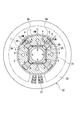
- FIG. 1 is a sectional view of a permanent magnet type rotating electric machine according to a first embodiment of the present invention.
- FIG. 2 is a graph of magnetic characteristics of a low coercivity permanent magnet and a high coercivity permanent magnet employed in the rotor permanent magnet in the above embodiment.
- FIG. 3 illustrates the magnetic flux (linkage magnetic flux is maximum) of the permanent magnet when the permanent magnet is irreversibly magnetized with a d-axis current energized for a short time to be in a magnetized state in the rotor of the above embodiment.
- FIG. 4 is an explanatory diagram of the magnetic flux of the demagnetizing magnetic field due to the d-axis current energized for a short time in the rotor of the above embodiment.
- FIG. 1 is a sectional view of a permanent magnet type rotating electric machine according to a first embodiment of the present invention.
- FIG. 2 is a graph of magnetic characteristics of a low coercivity permanent magnet and a high coercivity permanent magnet
- FIG. 5 shows the magnetic flux of the permanent magnet after the demagnetizing magnetic field due to the d-axis current energized for a short time (after the disappearance of the magnetic field due to the d-axis current) in the rotor of the above embodiment (the interlinkage magnetic flux is minimum).
- FIG. FIG. 6 is an explanatory diagram of a magnetic field caused by a positive d-axis current and a magnetic field caused by a load current (q-axis current) in the rotor according to the embodiment.
- FIG. 7 is a block diagram of the permanent magnet motor drive system according to the first embodiment of the present invention.
- FIG. 8 is a simplified model diagram of a variable magnetic flux permanent magnet motor.
- FIG. 9 is a BH characteristic diagram of the permanent magnet type rotating electrical machine according to the embodiment.
- FIG. 10 is a block diagram showing an internal configuration of a magnetization request generation unit in the permanent magnet motor drive system of the embodiment.
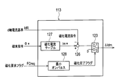
- FIG. 11 is a block diagram showing an internal configuration of a variable magnetic flux control unit in the permanent magnet motor drive system of the embodiment.
- FIG. 12 is a timing chart of motor control by the permanent magnet motor drive system of the above embodiment.
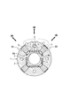
- FIG. 13 is an explanatory view of a cross section of a rotor and magnetic fluxes in a permanent magnet type rotating electric machine according to a fourth embodiment of the present invention.
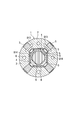
- FIG. 14 is a cross-sectional view of a rotor in a permanent magnet type rotating electric machine according to a fifth embodiment of the present invention.
- FIG. 10 is a block diagram showing an internal configuration of a magnetization request generation unit in the permanent magnet motor drive system of the embodiment.
- FIG. 11 is a block diagram showing an internal configuration of a variable magnetic flux control
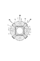
- FIG. 15 is a sectional view of a rotor in a permanent magnet type rotating electric machine according to an eighth embodiment of the present invention.
- FIG. 16 is a cross-sectional view of a permanent magnet type rotating electric machine according to a ninth embodiment of the present invention.
- FIG. 17 is a block diagram of a permanent magnet motor drive system according to an eleventh embodiment of the present invention.
- FIG. 18 is a block diagram showing an internal configuration of a variable magnetic flux control unit in the permanent magnet motor drive system of the embodiment.
- FIG. 19 is a timing chart of motor control by the permanent magnet motor drive system of the above embodiment.
- FIG. 20 is a cross-sectional view of a conventional embedded permanent magnet motor.
- FIG. 1 shows a structure of a permanent magnet type rotating electrical machine according to the present embodiment, in which a rotor 1 is accommodated inside a stator 20 so as to face each other through an air gap 23.
- the stator 20 is the same as that of the conventional example and is the same as that shown in FIG.
- the rotor 1 in the permanent magnet type rotating electrical machine of the present embodiment includes a rotor core 2, a first permanent magnet 3 having a small product of coercive force and magnetization direction thickness, coercive force and It is comprised from the 2nd permanent magnet 4 from which the product of a magnetization direction thickness becomes large.
- the rotor core 2 is formed by laminating silicon steel plates.
- the first permanent magnet 3 having a small product of the coercive force and the magnetization direction thickness is an AlNiCo magnet, and four embedded in the radial cross section of the rotor core 2. ing.
- An FeCrCo magnet may be applied to the first permanent magnet 3.
- the second permanent magnets 4 having a large product of the coercive force and the magnetization direction thickness are NdFeB magnets, and four are embedded in the radial cross section of the rotor core 2.
- the first permanent magnet 3 made of an AlNiCo magnet is disposed substantially along the radial direction of the rotor 1 and has a trapezoidal cross section.
- the magnetization direction of the first permanent magnet 3 is substantially the circumferential direction, and the average thickness of the magnetization direction is 6 mm in this embodiment (depending on the specifications).
- the 2nd permanent magnet 4 which consists of a NdFeB magnet is arrange
- the magnetization direction of the second permanent magnet 4 is substantially the radial direction, and the thickness in the magnetization direction is 2 mm in the present embodiment.
- FIG. 2 shows the magnetic characteristics of an Alnico magnet for the first permanent magnet 3 (AlNiCo magnet), an FeCrCo magnet, and an NdFeB magnet for the second permanent magnet 4 applied to the present embodiment.
- the coercive force of the AlNiCo magnet (magnetic field at which the magnetic flux density becomes 0) is 60 to 120 kA / m, which is 1/15 to 1/8 of the 950 kA / m of the NdFeB magnet.
- the coercive force of the FeCrCo magnet is about 60 kA / m, which is 1/15 of 950 kA / m of the NdFeB magnet.
- AlNiCo magnets and FeCrCo magnets have a much lower coercivity than NdFeB magnets.
- a break point where a magnetic flux density changes reversibly by applying an external magnetic field to a irreversible magnetization region where magnetic flux density changes irreversibly by applying an external magnetic field that is, a knick point is the first point.
- the AlNiCo magnet (AlNiCo) for the permanent magnet 3 is at a position of 0.6 T or more, and the FeCrCo magnet is at a position of 0.8 T or more.
- the NdFeB magnet for the second permanent magnet 4 no knick point is seen in the second quadrant and the fourth quadrant, and the magnetic flux density is reversibly changed by applying an external magnetic field.
- the magnetic flux due to the d-axis current passes through the two NdFeB permanent magnets 4 (two adjacent NdFeB permanent magnets 4 of different polarities).
- the magnetic field acts on one NdFeB permanent magnet 4 per pole.
- the AlNiCo permanent magnet 3 since the magnetic flux due to the d-axis current passes through one AlNiCo permanent magnet 3 between the magnetic poles, the magnetic field due to the d-axis current is 1 ⁇ 2 of the NdFeB permanent magnet 4 per pole.
- the thickness of the AlNiCo permanent magnet 3 may be evaluated as 1/2.
- an AlNiCo magnet having a coercive force of 120 kA / m is applied to the first permanent magnet 3 in which the product of the coercive force and the magnetization direction thickness is small.
- An NdFeB magnet having a coercive force of 1000 kA / m is applied to the second permanent magnet 4 having a large product of the coercive force and the magnetization direction thickness.
- the product of the coercive force and the magnetization direction thickness of the NdFeB permanent magnet 4 is 5.6 times as large as that of the AlNiCo permanent magnet 3.
- the low coercivity AlNiCo permanent magnet 3 is embedded in the rotor core 2, and cavities 5 are provided at both ends of the AlNiCo permanent magnet 3.
- the AlNiCo permanent magnet 3 is disposed along the radial direction of the rotor 1 that coincides with the q axis that is the central axis between the magnetic poles.
- the direction of easy magnetization of the AlNiCo permanent magnet 3 is substantially the circumferential direction, and the direction perpendicular to the radius (in FIG. 1, the trapezoidal section of the AlNiCo permanent magnet 3 is equally divided into two and perpendicular to the line passing through the rotation center). .
- a high coercive force NdFeB permanent magnet 4 is also embedded in the rotor core 2, and cavities 5 are provided at both ends of the NdFeB permanent magnet 4.
- the NdFeB permanent magnet 4 is disposed substantially in the circumferential direction of the rotor 1 so as to be sandwiched between the two AlNiCo permanent magnets 3 on the inner peripheral side of the rotor 1.
- the direction of easy magnetization of the NdFeB permanent magnet 4 is substantially perpendicular to the circumferential direction of the rotor 1 (in FIG. 1, perpendicular to the long side of the rectangular cross section of the NdFeB permanent magnet 4).
- the magnetic pole core portion 7 of the rotor core 2 is formed so as to be surrounded by two AlNiCo permanent magnets 3 and one NdFeB permanent magnet 4.
- the central axis direction of the magnetic core part 7 of the rotor core 2 is the d axis
- the central axis direction between the magnetic poles is the q axis. Therefore, the AlNiCo permanent magnet 3 is disposed in the q-axis direction that is the central axis between the magnetic poles
- the magnetization direction of the AlNiCo permanent magnet 3 is 90 ° or ⁇ 90 ° with respect to the q-axis.
- the magnetic pole faces facing each other are the same.
- the NdFeB permanent magnet 4 is disposed in a direction perpendicular to the d-axis that is the central axis of the magnetic core 6, and the magnetization direction is 0 ° or 180 ° with respect to the d-axis. In the adjacent NdFeB permanent magnets 4, the directions of the magnetic poles are opposite to each other.
- FIG. 7 is a control block diagram of a permanent magnet motor drive system 100 for rotationally driving the permanent magnet type rotating electric machine according to the first embodiment of the present invention as an electric motor.
- a variable magnetic flux motor as a permanent magnet synchronous motor (PM motor) will be described.
- An image of the variable magnetic flux motor 101 is shown in FIG.
- the stator side is the same as the conventional electric motor.
- On the rotor 151 side as permanent magnets, there are a fixed magnet FMG whose magnetic flux density is fixed and a variable magnet VMG whose magnetic flux density is variable.
- the conventional PM motor has only the former fixed magnet FMG, whereas the variable magnetic flux motor 1 is characterized in that the variable magnet VMG is provided.
- a permanent magnet maintains a magnetized state in the state where no current flows from the outside, and the magnetic flux density does not change strictly under any condition. Even a conventional PM motor may be demagnetized by passing an excessive current through an inverter or the like. Therefore, the permanent magnet means that the amount of magnetic flux is not constant and the magnetic flux density is not substantially changed by a current supplied from an inverter or the like in a state close to normal rated operation.
- the above-described permanent magnet having a variable magnetic flux density that is, a variable magnet refers to a magnet whose magnetic flux density changes due to a current that can be passed through an inverter or the like even under the above operating conditions.
- Such a variable magnet VMG can be designed within a certain range depending on the material and structure of the magnetic material.
- recent PM motors often use NdFeB magnets (neodymium magnets) with high residual magnetic flux density Br.
- the residual magnetic flux density Br is as high as about 1.2 T, it is possible to output a large torque with a small device size, and it is suitable for a hybrid vehicle (HEV) or a train that requires a high-output miniaturization of the electric motor. It is.
- HEV hybrid vehicle
- a train that requires a high-output miniaturization of the electric motor. It is.
- it is a requirement that the magnet is not demagnetized by a normal current.
- this NdFeB magnet (neodymium magnet) has a very high coercive force Hc of about 1000 kA / m. It is the most suitable magnetic material. This is because a magnet having a large residual magnetic flux density and a large coercive force is selected for the PM motor.
- the magnetic flux density (magnetic flux amount) of the NdFeB magnet is substantially constant due to the normal amount of current (meaning the amount of current flowing when the conventional PM motor is driven by the inverter), and the magnetic flux of the variable magnet VMG such as an AlNiCo magnet is constant.
- the density (magnetic flux amount) is variable.
- the NdFeB magnet as the fixed magnet FMG is also used in the reversible region, the magnetic flux density fluctuates in a very small range, but returns to the original value when the inverter current disappears.
- the variable magnet VMG is used up to the irreversible region, even if the inverter current disappears, the initial value is not obtained.
- the amount of magnetic flux of the AlNiCo magnet, which is the variable magnet VMG is almost zero in the q-axis direction only by the amount in the d-axis direction varying.
- FIG. 9 illustrates the BH characteristics (magnetic flux density-magnetization characteristics) of the fixed magnet FMG and the variable magnet VMG.
- FIG. 10 shows only the second quadrant of FIG. 9 in a quantitatively correct relationship.
- the Hc1 of the AlNiCo magnet is 1/15 to 1/1/0 of the Hd of the NdFeB magnet.
- Hc1 of FeCrCo magnet is 1/15.
- the magnetization region due to the output current of the inverter is sufficiently smaller than the coercive force of the NdFeB magnet and is used in the reversible range of its magnetization characteristics.
- the coercive force of the variable magnet is small as described above, it can be used in the irreversible region (even if the current is zero, it does not return to the magnetic flux density B before the current application) in the inverter output current range.
- the magnetic flux density can be made variable.
- Equation (1) An equivalent simple model of the dynamic characteristics of the variable magnetic flux motor 1 is shown in Equation (1).
- the model is a model on the dq axis rotational coordinate system in which the d axis is a magnet magnetic flux direction and the q axis is a direction perpendicular to the d axis.
- R1 is a winding resistance
- Ld is a d-axis inductance
- Lq is a q-axis inductance
- ⁇ fix is a magnetic flux amount of a fixed magnet
- ⁇ var is a magnetic flux amount of a variable magnet
- ⁇ 1 is an inverter frequency.
- FIG. 7 shows a main circuit 100A and a control circuit 100B of the permanent magnet motor drive system 100 according to the first embodiment.
- the main circuit 100A includes a DC power source 103, an inverter 104 that converts DC power into AC power, and a variable magnetic flux permanent magnet motor 101 that is driven by AC power of the inverter 104.
- the main circuit 100A is provided with an alternating current detector 102 for detecting electric motor power and a speed detector 118 for detecting electric motor speed.
- the inputs here are the operation command Run * and the torque command Tm *.
- the gate command generation unit 115 receives the operation state flag Run, and generates and outputs a gate command Gst to the switching element included in the inverter 104.
- ⁇ min is the minimum amount of magnetic flux (> 0) that can be taken as the variable magnetic flux motor 101
- ⁇ max is the maximum amount of magnetic flux that can be taken as the variable magnetic flux motor 101
- ⁇ A is a predetermined rotational frequency. The setting of the magnetic flux amounts ⁇ min and ⁇ max will be described later at the variable magnetic flux control unit 113.
- the current reference calculation unit 111 receives the torque command Tm * and the magnetic flux command ⁇ * and calculates the d-axis current reference IdR and the q-axis current reference IqR as in the following equations (3) and (4).
- the expressions (3) and (4) are arithmetic expressions assuming that the reluctance torque of the motor is not used and the number of motor poles is zero. Even a salient pole type motor having a difference ⁇ L between the d-axis inductance Ld and the q-axis inductance Lq may be a non-salient pole type motor having no difference.
- K is the ratio between the d-axis current and the q-axis current, and is a value that varies depending on the application, such as the aforementioned efficiency optimization and maximum output. To optimize, it takes a function form and uses torque, speed, etc. as its arguments. In addition, simple approximation or a table can be used. Further, the magnetic flux command ⁇ * in the equation (5) can be operated even when a magnetic flux estimated value ⁇ h described later is used.
- the detailed configuration of the magnetization request generator 129 is shown in FIG.
- the block in FIG. 10 is controlled at predetermined intervals by the control microcomputer.
- the magnetic flux command ⁇ * is input to the previous value holding unit 131 and the value is held.
- the output of the previous value holding unit 131 is the previously stored magnetic flux command ⁇ * and is input to the change determination unit 130 together with the current magnetic flux command value ⁇ *.
- the change determination unit 130 outputs 1 when there are two input changes, and 0 when there is no change. That is, 1 is set only when the magnetic flux command ⁇ * changes.
- the same circuit as described above is provided for the operation state flag Run instead of the magnetic flux command ⁇ *, and is input to the previous value holding unit 133 to hold the value.
- the output of the previous value holding unit 133 is the operation state flag Run stored last time, and is input to the change determination unit 134 together with the current operation state flag Run.
- the outputs of the two change determination units 130 and 134 are input to the logical sum operation unit (OR) 132, and the logical sum of these is output as the magnetization request flag FCreq.
- the state in which the operation state flag Run changes is when the inverter starts, stops, or stops due to protection.
- the magnetization request FCreq may be generated by a change in a magnetization current command Im * (output of the magnetization current table 127) of the variable magnetic flux control unit 113 described later.
- FIG. 11 shows a detailed configuration of the variable magnetic flux control unit 113.
- the variable magnetic flux control unit 113 receives the magnetic flux command ⁇ * that is the output of the magnetic flux command calculation unit 112, and outputs a d-axis magnetization current difference amount ⁇ Idm * that corrects the d-axis current reference IdR.
- the generation of the magnetizing current difference amount ⁇ Idm * is performed by the following arithmetic processing.
- a predetermined magnetizing current command Im * may be obtained in accordance with the BH characteristics of the variable magnet shown in FIG.
- the magnitude of the magnetization current command Im * is set to be equal to or greater than H1sat in FIG. 9, that is, the magnetization saturation region of the variable magnet.
- the amount of magnetic flux ⁇ min and ⁇ max to be set by the magnetic flux command calculation unit 112 is added to the maximum (saturation) value of the variable magnet's magnetic flux (magnetic flux density) plus or minus. Set as the value. If the positive maximum value of the magnetic flux amount of the variable magnet VMG is ⁇ varmax (assuming that the absolute value of the negative maximum value is equal to the positive maximum value) and the magnetic flux amount of the fixed magnet FMG is ⁇ fix, the following equation is obtained.
- the magnetic flux command ⁇ * is input, and the magnetizing current command Im * for obtaining the magnetic flux command ⁇ * is output from the magnetizing current table 127 storing the corresponding magnetizing current.
- the magnetizing current command Im * is given to the d-axis current command Id *.
- the d-axis current reference IdR which is an output from the current reference calculation unit 111, is corrected with the d-axis magnetization current command difference ⁇ Idm * to obtain the d-axis current command Id *.
- the d-axis magnetizing current command ⁇ Idm * is obtained by the following equation.
- the magnetization request flag FCreq In order to make the magnetic flux variable, the magnetization request flag FCreq is input to the minimum on-pulse device 128.
- the voltage command calculation unit 110 Based on the dq-axis current commands Id * and Iq * generated as described above, the voltage command calculation unit 110 generates dq-axis voltage commands Vd * and Vq * including a current controller so that a current matching the command flows. To do.
- the dq axis voltage commands Vd * and Vq * of the voltage command calculation unit 110 are converted into three-phase voltage commands Vu *, Vv * and Vw * by the coordinate conversion unit 105, and the PWM circuit 106 is converted by this three-phase voltage command.
- a gate signal is generated by PWM, and the inverter 104 is PWM-controlled.
- the coordinate conversion unit 107 converts the AC detection currents Iu and Iw of the current detector 102 into two-axis dq axes, converts them into dq-axis current detection values Id and Iq, and inputs them to the voltage command calculation unit 110.
- the pseudo-differentiator 108 obtains the inverter frequency ⁇ 1 from the signal from the speed detector 118.
- the voltage command calculation unit 110, the coordinate conversion units 105 and 107, and the PWM circuit 106 employ known techniques similar to those in the prior art.
- FIG. 12 shows an example of a timing chart of the operation of each signal.
- the magnetization request flag is raised by the change of the operation state flag Run and the change of the magnetic flux command ⁇ *
- the magnetization completion flag for securing the predetermined time width is raised.
- the magnetization current command Im * has a value only during the period of the magnetization completion flag.
- the magnetomotive force required for magnetization per pole is approximated by the product of the magnetic field required for magnetization and the thickness of the permanent magnet per pole.
- the first permanent magnet 3 of the AlNiCo magnet can be magnetized to nearly 100% with a magnetic field of 250 kA / m.
- the second permanent magnet 4 of the NdFeB magnet can be magnetized to nearly 100% with a magnetic field of 1500 to 2500 kA / m.
- the NdFeB permanent magnet 4 is in a reversible demagnetized state, and the NdFeB permanent magnet 4 can maintain the magnetic flux in the state before magnetization even after magnetization.
- a magnetic field is formed by applying a pulsed current having an energization time of an extremely short time (about 1 ms to 10 ms) to the armature winding 21 of the stator 20, and the magnetic field is applied to the AlNiCo permanent magnet 3.
- the energization time varies depending on the winding inductance of the rotating electrical machine and the current waveform.
- a pulse current that forms a magnetic field for magnetizing the permanent magnet is a d-axis current component of the armature winding 21 of the stator 20.
- the magnetizing magnetic field is 250 kA / m, ideally, a sufficient magnetizing magnetic field acts on the AlNiCo permanent magnet 3, and the NdFeB permanent magnet 4 does not undergo irreversible demagnetization due to magnetization.
- FIG. 3 shows the magnetic flux of each permanent magnet when a magnetic field is applied so that the magnetic fluxes of the AlNiCo permanent magnet 3 and the NdFeB permanent magnet 4 are added together at the magnetic pole and the air gap surface.
- the flux linkage between the first permanent magnet 3 of the AlNiCo magnet and the second permanent magnet 4 of the NdFeB magnet is increased to be in a magnetized state.
- the magnetizing magnetic field is formed by passing a pulse-like current for a very short time through the armature winding 21 of the stator 20.
- the current that is energized at this time is a d-axis current component.
- the pulse current immediately becomes 0 and the magnetizing magnetic field disappears, but the first permanent magnet 3 of the AlNiCo magnet changes irreversibly and generates a magnetic flux B3 in the magnetizing direction.
- B4 is a magnetic flux generated by the second permanent magnet 4 of the NdFeB magnet.
- the magnetic flux distributions in FIGS. 3, 4 and 5 show only one pole.
- FIG. 4 shows the action when the flux linkage is reduced.
- a magnetic field Bd formed by applying a negative d-axis current to the armature winding 21 generates a magnetic flux in the direction opposite to that in FIG.
- a magnetic field Bd created by the negative d-axis current of the armature winding 21 acts on the AlNiCo permanent magnet 3 and the NdFeB permanent magnet 4 from the center of the magnetic pole of the rotor 1 in a direction almost opposite to the magnetization direction.
- the AlNiCo permanent magnet 3 Since the AlNiCo permanent magnet 3 has a small product of the coercive force and the magnetization direction thickness, the magnetic flux of the AlNiCo permanent magnet 3 is irreversibly reduced by this reverse magnetic field.
- the NdFeB permanent magnet 4 since the NdFeB permanent magnet 4 has a large product of coercive force and magnetization direction thickness, the magnetic characteristics are in a reversible range even when subjected to a reverse magnetic field, and the magnetized state after the magnetization magnetic field Bd caused by the negative d-axis current disappears. There is no change and the amount of magnetic flux does not change. Therefore, only the AlNiCo permanent magnet 3 is demagnetized, and the amount of flux linkage can be reduced.
- the flux linkage can be greatly reduced, and in particular, the flux linkage can be reduced to zero.
- FIG. 5 shows a state after magnetization (magnetization) by a negative d-axis current.
- the magnetic flux B3 of the AlNiCo permanent magnet 3 generated in the opposite direction to the magnetic flux B4 of the NdFeB permanent magnet 4 is canceled out, and the magnetic flux of the air gap 23 is almost zero when the magnetic flux amounts B3 and B4 of the permanent magnets 3 and 4 are the same. it can.
- the magnetic flux B4 of the NdFeB permanent magnet 4 is canceled and a magnetic circuit with the AlNiCo permanent magnet 3 can be formed, so that a large amount of magnetic flux is distributed in the rotor 1.
- the magnetic flux distribution of the air gap magnetic flux density can be uniformly distributed to zero.
- the magnetic flux B3 of the AlNiCo permanent magnet 3 is caused by the magnetic field due to the d-axis current in the AlNiCo permanent magnet 3 having the opposite polarity in the linkage flux 0. Decrease.
- the AlNiCo permanent magnet 3 has a reverse polarity, the magnetic field applied to the AlNiCo permanent magnet 3 is in the same direction as the original magnetization direction of the AlNiCo permanent magnet 3 shown in FIG. That is, the direction is opposite to the magnetic field Bd due to the d-axis current shown in FIG.
- the AlNiCo permanent magnet 3 When the linkage flux is further increased to return to the original maximum linkage flux state, the AlNiCo permanent magnet 3 reverses the polarity again (returns to the original polarity) and returns to the state of FIG. Therefore, in the case of the permanent magnet type rotating electrical machine of the present embodiment, the AlNiCo permanent magnet 3 has a magnetic characteristic (BH curve which is a characteristic relating to magnetic flux density and magnetic field) in the entire range from the first quadrant to the fourth quadrant. It can be operated.
- BH curve which is a characteristic relating to magnetic flux density and magnetic field
- the permanent magnet in the conventional permanent magnet type rotating electric machine is operated only in the second quadrant. Further, the conventional permanent magnet type rotating electrical machine generates a magnetic flux due to the negative d-axis current of the armature winding 21 in order to reduce the interlinkage magnetic flux, thereby canceling the magnetic flux of the permanent magnet 4 of the rotor 1. .
- the fundamental interlinkage magnetic flux can be reduced only to about 50%, and the harmonic magnetic flux increases considerably, which causes a problem in that a harmonic voltage and a harmonic iron loss are generated. Therefore, it is extremely difficult to set the interlinkage magnetic flux to 0. Even if the fundamental wave can be reduced to 0, the harmonic magnetic flux has a considerably large value.
- the rotor 1 can be uniformly reduced by the magnetic flux of only the permanent magnets 3 and 4, so that the harmonic magnetic flux is small and the loss is not increased.
- the magnetic field due to the d-axis current acts on the NdFeB permanent magnet 4 for two permanent magnets (two permanent magnets of N pole and S pole).
- the magnetic field acting on the NdFeB permanent magnet 4 is about half of the magnetic field acting on the AlNiCo permanent magnet 3 even at this point alone. Therefore, in the rotating electrical machine of the present embodiment, the first permanent magnet 3 having a small product of the coercive force and the magnetization direction thickness is easily magnetized by the magnetic field due to the d-axis current.
- the NdFeB permanent magnet 4 has a product of the magnetizing magnetic field and the thickness of the magnet four times that of the AlNiCo permanent magnet 3, and further, in terms of the arrangement configuration, the magnetic field due to the d-axis current acting on the NdFeB permanent magnet 4 is AlNiCo permanent magnet 3. 1/2 of this. Therefore, in order to magnetize the NdFeB permanent magnet 4, a magnetomotive force 8 times that of the AlNiCo permanent magnet 3 is required. That is, if the magnetic field is sufficient to magnetize the AlNiCo permanent magnet 3, the NdFeB permanent magnet 4 is in a reversible demagnetization state, and the NdFeB permanent magnet 4 can maintain the magnetic flux in the state before magnetization even after magnetization.
- the magnetic field of the NdFeB permanent magnet 4 acts as a bias magnetic field on the AlNiCo permanent magnet 3, and the magnetic field due to the negative d-axis current and the magnetic field due to the NdFeB permanent magnet 4 act on the AlNiCo permanent magnet 3. It becomes easy to magnetize.
- the product of the coercive force and the magnetization direction thickness of the AlNiCo permanent magnet 3 is equal to or greater than the product of the magnetic field strength and the magnetization direction thickness at the operating point of the NdFeB permanent magnet 4 when no load is applied.
- the magnetic field of the NdFeB permanent magnet 4 is overcome and a magnetic flux amount is generated.
- the amount of interlinkage magnetic flux of the AlNiCo permanent magnet 3 can be greatly changed from the maximum to 0 by the d-axis current, and the magnetization direction can be changed in both forward and reverse directions.
- the linkage flux B4 of the NdFeB permanent magnet 4 is the positive direction
- the linkage flux B3 of the AlNiCo permanent magnet 3 can be adjusted over a wide range from the maximum value in the positive direction to 0, and further to the maximum value in the reverse direction.
- the amount of total interlinkage magnetic flux combining the AlNiCo permanent magnet 3 and the NdFeB permanent magnet 4 is adjusted over a wide range by magnetizing the AlNiCo permanent magnet 3 with the d-axis current. be able to.
- the AlNiCo permanent magnet 3 is magnetized with a d-axis current so as to have a maximum value in the same direction as the interlinkage magnetic flux of the NdFeB permanent magnet 4 (magnetization state shown in FIG. 3 described above).
- the torque by the permanent magnet is maximized, the torque and output of the rotating electrical machine can be maximized.
- the magnetic flux amount of the AlNiCo permanent magnet 3 is irreversibly lowered by the magnetic field Bd by the d-axis current of FIG.
- the voltage of the rotating electrical machine is lowered, so that there is a margin with respect to the upper limit value of the power supply voltage, and the rotational speed (frequency) can be further increased.
- the maximum speed is remarkably increased (the variable speed range is further expanded, for example, the range of variable speed operation more than three times the base speed)
- the AlNiCo permanent magnet 3 is in the opposite direction to the flux linkage of the NdFeB permanent magnet 4. Magnetization (the direction of the magnetic flux B3 of the AlNiCo permanent magnet 3 is the state shown in FIG.
- the total interlinkage magnetic flux of the permanent magnets 3 and 4 is the difference of the interlinkage magnetic flux between the NdFeB permanent magnet 4 and the AlNiCo permanent magnet 3 and can be made the smallest. Since the voltage of the rotating electrical machine is also minimized, the rotational speed (frequency) can be increased to the maximum value.
- the permanent magnet type rotating electrical machine of the present embodiment and the permanent magnet motor drive system that rotationally drives it, a wide range of variable speed operation from low speed rotation to high speed rotation can be realized with high output. Further, according to the permanent magnet type rotating electrical machine of the present embodiment, since the magnetizing current when changing the flux linkage is passed for an extremely short time, the loss can be remarkably reduced, and the efficiency is high over a wide operation range.
- the AlNiCo permanent magnet 3 is disposed in the vicinity of the q axis so that the magnetization direction is a direction perpendicular to the q axis direction.
- the magnetization direction of the AlNiCo permanent magnet 3 and the magnetic field due to the q-axis current are ideally orthogonal to each other, and the magnetic field due to the q-axis current is not greatly affected.
- the magnetic field generated by the q-axis current as the load current becomes considerably large.
- the magnetic field due to the excessive q-axis current irreversibly demagnetizes the permanent magnet on the q-axis. That is, when the torque is generated by the q-axis current, the permanent magnet is demagnetized and the torque is reduced.
- FIG. 6 schematically shows the action of a magnetic field when a positive d-axis current is superimposed when torque is generated.
- B3i represents a magnetic field due to a positive d-axis current
- B5i represents a magnetic field due to a load current (q-axis current)
- B6 represents magnetization of the first permanent magnet 3 having a small product of coercive force and magnetization direction thickness. Shows direction.
- the two types of permanent magnets 3 and 4 in each magnetic pole are in the direction of addition, and in this state, the positive d-axis current is in the same direction as the magnetization direction of the permanent magnet 3. Therefore, as shown in FIG. 6, the magnetic field B3i produced by the positive d-axis current acts in the permanent magnet 3 so as to cancel the demagnetizing field due to the q-axis current. For this reason, if this embodiment is applied, even if the first permanent magnet 3 having a small product of the coercive force and the thickness is used, the aforementioned irreversible demagnetization of the permanent magnet 3 is suppressed even in a state where a large torque is generated. Thus, a decrease in torque due to the magnetic field B5i of the load current can be suppressed, and a large torque can be generated.
- the cavity 5 relaxes stress concentration and demagnetizing field on the rotor core 2 when centrifugal force by the permanent magnets 3 and 4 acts on the rotor core 2.
- the rotor core 2 can have a curved shape, and the stress is relieved.
- the magnetic field due to the current is concentrated on the corners of the permanent magnets 3 and 4 and a demagnetizing field acts, and the corners are irreversibly demagnetized.
- the cavity 5 is provided at each end of the permanent magnets 3 and 4, the demagnetizing field due to the current at the end of the permanent magnet is alleviated.
- the structural strength of the rotor 1 in this embodiment will be described.
- the AlNiCo permanent magnet 3 and the NdFeB permanent magnet 4 are embedded in the rotor core 2, and the permanent magnets 3 and 4 are fixed by the rotor core 2.
- a bolt hole 6 is provided in the center of the magnetic core part 7 so that the rotor core 2 can be fastened with bolts and fixed to the rotor end plate and the shaft. I have to.
- the linkage flux of the NdFeB permanent magnet 4 is the positive direction
- the linkage flux of the AlNiCo permanent magnet 3 is changed from the maximum value in the positive direction to 0, and further, the polarity is reversed and adjusted in a wide range up to the maximum value in the reverse direction. can do.
- the AlNiCo permanent magnet 3 is operated in the entire range from the first quadrant to the fourth quadrant in terms of magnetic characteristics.
- the amount of total interlinkage magnetic flux combining the AlNiCo permanent magnet 3 and the NdFeB permanent magnet 4 can be adjusted over a wide range by magnetizing the AlNiCo permanent magnet 3 with the d-axis current.
- adjustment of the total interlinkage magnetic flux of the permanent magnet makes it possible to adjust the voltage of the rotating electrical machine over a wide range, and since magnetization is performed with a pulse-like current for a very short time, the flux current is constantly weakened and continues to flow. There is no need, and loss can be greatly reduced. Further, since it is not necessary to perform the flux-weakening control as in the prior art, harmonic iron loss due to harmonic magnetic flux does not occur.
- the permanent magnet type rotating electrical machine and the permanent magnet motor drive system of the present embodiment can perform variable speed operation over a wide range from high speed to low speed and high speed, and become highly efficient in a wide operating range.
- the AlNiCo permanent magnet 3 can be magnetized by the d-axis current to reduce the total interlinkage magnetic flux of the permanent magnets 3 and 4, so that the inverter electronic component is damaged by the induced voltage of the permanent magnet. And the reliability is improved.
- the total interlinkage magnetic flux of the permanent magnets 3 and 4 can be reduced by magnetizing the AlNiCo permanent magnet 3 with a negative d-axis current.
- the voltage is remarkably lowered, and it is almost unnecessary to constantly apply a weak magnetic flux current for lowering the induced voltage, and the overall efficiency is improved.
- the permanent magnet type rotating electrical machine of the present embodiment is mounted and driven on a commuter train with a long coasting operation time, the overall driving efficiency is greatly improved.
- the second permanent magnet 4 having a large product of the coercive force and the magnetization direction thickness is an NdFeB magnet, and the product of the coercive force and the magnetization direction thickness is
- the small first permanent magnet 3 is composed of an AlNiCo magnet, and the magnetic flux density ⁇ PM2 of the second permanent magnet 4 is determined by the second permanent magnet 4 when the rotational speed of the rotor 1 reaches the maximum rotational speed ⁇ .
- the magnitude of the back electromotive force is equal to or lower than the withstand voltage E of the inverter electronic component that is the power source of the rotating electric machine, that is, ⁇ PM2 ⁇ E / ⁇ ⁇ N (where N is the number of turns of the armature winding 21).
- This has the following effects. That is, the counter electromotive voltage by the permanent magnet increases in proportion to the rotation speed. This counter electromotive voltage is suppressed below the withstand voltage of the inverter electronic component or the power supply voltage by continuously flowing the d-axis current. However, when the control is impossible, the counter electromotive voltage becomes excessive and the electronic components of the inverter are broken down.
- the counter electromotive voltage of the permanent magnet is limited by the withstand voltage at the time of design, the amount of magnetic flux of the permanent magnet is reduced, and the output and efficiency in the low speed region of the motor are reduced.
- a magnetic field in the demagnetizing direction is generated by a short d-axis current to magnetize the permanent magnet irreversibly to reduce the interlinkage magnetic flux of the permanent magnets 3 and 4. Therefore, even if control becomes impossible during high-speed rotation, an excessive back electromotive voltage does not occur.
- the AlNiCo permanent magnet 3 is demagnetized or the polarity is reversed by the short circuit current, so the interlinkage magnetic flux by the permanent magnets 3 and 4 is the NdFeB permanent magnet. Only by 4 or 0 when polarity is reversed. Therefore, the short circuit current can be instantaneously reduced by the rotating electrical machine itself. Thus, it is possible to prevent the braking force due to the short circuit current and the heating due to the short circuit current.
- the permanent magnet type rotating electrical machine and the permanent magnet motor drive system generate high torque (high output) at low speed rotation, and can perform variable speed operation in a wide range from high speed to low speed to high speed. It is possible and high-efficiency operation is possible in a wide operation range. Furthermore, the back electromotive voltage during high-speed rotation can be suppressed, and the reliability of the drive system including the inverter can be improved.
- the first permanent magnet 3 of the AlNiCo magnet has a shape in which the magnetization direction thickness is not constant, and the cross section has a trapezoidal shape as shown in FIG.
- the AlNiCo magnet Since the AlNiCo magnet has a high residual magnetic flux density and a small coercive force, the magnetic flux density changes suddenly with respect to the magnetic field in a region where the magnetic flux density is low. Therefore, in order to finely adjust the magnetic flux density only by the magnetic field strength, high accuracy is required for the control of the magnetic field strength. Therefore, in the present embodiment, it is applied that the magnetizing force necessary for magnetization of the permanent magnet varies greatly depending on the thickness in the magnetization direction of the permanent magnet. In the present embodiment, since the AlNiCo permanent magnet 3 is trapezoidal, the thickness in the magnetization direction is not constant. Therefore, it is possible to change the amount of magnetic flux generated in the permanent magnet portion of each thickness when a magnetizing magnetic field is applied.
- the strength of the magnetizing magnetic field can largely depend on the influence of the thickness of the permanent magnet. This facilitates adjustment of the amount of magnetic flux with respect to the magnetic field due to the d-axis current, and can reduce variations in the amount of magnetic flux due to fluctuations in external conditions.
- the AlNiCo permanent magnet 3 is irreversibly applied to the permanent magnet rotating electric machine 101 shown in FIG. 1 by a permanent magnetic motor drive system shown in FIG. To change the amount of flux linkage. Furthermore, by always generating a magnetic flux due to a negative d-axis current in a medium-speed rotation region or a high-speed rotation region, the interlinkage magnetic flux composed of the magnetic flux due to the negative d-axis current and the magnetic flux due to the permanent magnets 3 and 4 is Fine adjustment can be made by the magnetic flux due to the negative d-axis current.
- the amount of flux linkage is greatly changed by irreversibly changing the magnetization state of the AlNiCo permanent magnet 3 with a pulsed magnetic field caused by a short d-axis current. Fine-tune the flux linkage with the d-axis current. At this time, since the amount of interlinkage magnetic flux that is finely adjusted by the negative d-axis current that is always energized is small, the negative d-axis current that is constantly flowing is small and no significant loss occurs.
- the amount of flux linkage which is the basis of the voltage can be varied and finely adjusted, and can be varied with high efficiency.
- FIG. 20 A permanent magnet type rotating electrical machine according to a fourth embodiment of the present invention will be described with reference to FIG.
- the structure of the stator 20 is the same as that of the first embodiment shown in FIG. 1 and the conventional example shown in FIG.
- an inverted U-shaped NdFeB permanent magnet 4 is embedded in the rotor core 2 so as to protrude toward the outer peripheral side, and the inverted U-shaped
- the central axis is a position that coincides with the d-axis.
- an AlNiCo permanent magnet 3 is arranged in the rotor core 2 in the radial direction.
- the inverted U-shaped NdFeB permanent magnet 4 is disposed so as to prevent the magnetic path Bq of the q-axis magnetic flux by using an inverted U-shape, the q-axis inductance can be reduced. Power factor can be improved from this. Further, the interval Wp between the outer peripheral side tip (center portion) of the inverted U-shaped NdFeB permanent magnet 4 and the outer periphery (air gap surface) of the rotor core 2 is almost magnetically saturated with the magnetic flux of the AlNiCo permanent magnet 3 and the NdFeB permanent magnet 4. Don't do it. If the magnetic flux density at the center of the magnetic pole core 7 is about 1.9 T at the maximum, the magnetic flux distribution in the air gap is not distorted and the magnetic flux of the permanent magnet can be used effectively.
- FIG. 20 A permanent magnet type rotating electrical machine according to a fifth embodiment of the present invention will be described with reference to FIG.
- the structure of the stator 20 in the permanent magnet type rotating electrical machine of the present embodiment is the same as that of the first embodiment shown in FIG. 1 and the conventional example shown in FIG.
- the first permanent magnet 3 of the AlNiCo magnet is disposed in the rotor core 2 in the radial direction about the q axis, and the second permanent magnet of the NdFeB magnet.
- the magnet 4 is disposed in the rotor core 2 at right angles to the d-axis so as to contact the circumferential direction.
- the rotor 1 is configured to be fitted into an iron shaft 9 on the inner peripheral side of the rotor core 2.
- the shaft 9 has a shape in which four surfaces are cut, and an air layer 8 is formed between the rotor core 2 and the shaft 9.
- the shaft 9 can be made of a nonmagnetic material such as stainless steel.
- the magnetic field due to the current of the armature winding 21 for magnetizing the permanent magnet acts on the AlNiCo permanent magnet 3 and the NdFeB permanent magnet 4, and a magnetic flux due to the current flows as indicated by arrows B13 and B14 in FIG. Since the air layer 8 is present, the magnetic flux caused by the current does not pass through the shaft 9 but tends to pass through the narrow core portion on the inner peripheral side between the NdFeB permanent magnets 4 and 4. However, since this narrow iron core portion is easily magnetically saturated, the magnetic flux passing through the NdFeB permanent magnet 4 generated by the magnetic field due to the armature current can be reduced.
- the magnetic flux due to the current of the AlNiCo permanent magnet 3 to be magnetized increases, and at the same time, the magnetic flux due to the current passing through the NdFeB permanent magnet 4 decreases, thereby relaxing the magnetic saturation of the rotor magnetic pole core portion 7 and the stator core 22. Is done. Therefore, the d-axis current for magnetizing the AlNiCo permanent magnet 3 can be reduced.
- the shaft 9 is made of a non-magnetic material, the magnetic flux leaking to the shaft 9 is reduced, the magnetic flux passing through the NdFeB permanent magnet 4 is further reduced, and the magnetic saturation of the rotor magnetic pole core portion 7 and the stator core 22 is further alleviated. Is done.
- FIG. 1 A sixth embodiment of the present invention will be described.
- This embodiment is an NdFeB magnet having a small amount of Dy element as the second permanent magnet 4 having a large product of the coercive force and the magnetization direction thickness in the rotor 1 in the permanent magnet type rotating electrical machine of the first to fifth embodiments. Consists of. Since there are few Dy elements, a residual magnetic flux density becomes high and the residual magnetic flux density of 1.3 T or more is obtained at 20 degreeC.
- the amount of interlinkage magnetic flux that is a voltage is adjusted by irreversibly magnetizing the AlNiCo permanent magnet 3. Therefore, the flux weakening control in which an excessive reverse magnetic field acts on the NdFeB permanent magnet 4 is not used. In some cases, weakening control for fine adjustment is used. However, since the current is small, the reverse magnetic field can be extremely small. As a result, the rotating electrical machine of the present embodiment can be applied with an NdFeB magnet having a low coercive force and a high residual magnetic flux density that could not be used for a conventional rotating electrical machine due to demagnetization. The air gap magnetic flux density becomes high and high output is obtained.
- a magnet having a small coercive force but a magnetic flux density of 1.17 times can be applied, and a high output can be expected about 1.17 times.
- the thickness of the magnet is increased for resistance to demagnetization without contributing to the output.
- the rotating electric machine of the present embodiment has a small demagnetizing field, the amount of NdFeB magnet used can be reduced. .
- it becomes possible to apply an NdFeB magnet with little Dy element added it can be manufactured stably in the future.
- the second permanent magnet 4 having a large product of the coercive force and the magnetization direction thickness in the rotor 1 is an NdFeB magnet, and the product of the coercive force and the magnetization direction thickness.
- the first permanent magnet 3 having a small diameter is composed of an AlNiCo magnet.
- the back electromotive force generated by the NdFeB permanent magnet 4 is set to be equal to or lower than the withstand voltage of the inverter electronic component that is the power source of the rotating electrical machine.
- the back electromotive force generated by the permanent magnet increases in proportion to the rotation speed.
- this counter electromotive voltage is applied to the electronic component of the inverter and exceeds the withstand voltage of the electronic component, the electronic component breaks down. Therefore, in the conventional permanent magnet rotating electrical machine, the counter electromotive voltage of the permanent magnet is limited by the withstand voltage at the time of design, the amount of magnetic flux of the permanent magnet is reduced, and the output and efficiency in the low speed region of the motor are reduced.
- the permanent magnet when rotating at high speed, the permanent magnet is irreversibly magnetized by a magnetic field in the demagnetization direction by a negative d-axis current, and the magnetic flux of the AlNiCo permanent magnet 3 is reduced to near zero. Since the counter electromotive voltage caused by the AlNiCo permanent magnet 3 can be made substantially zero, the counter electromotive voltage caused by the NdFeB permanent magnet 4 whose magnetic flux amount cannot be adjusted may be made lower than the withstand voltage at the maximum rotation speed. That is, the amount of magnetic flux of only the NdFeB permanent magnet 4 is reduced until it reaches the withstand voltage or less. On the other hand, at the time of low speed rotation, the amount of interlinkage magnetic flux by the AlNiCo permanent magnet 3 and the NdFeB permanent magnet 4 magnetized so as to have the maximum magnetic flux amount can be increased.
- the AlNiCo permanent magnet 3 is magnetized in the opposite direction to that at low speed in the maximum speed range, so the total flux linkage is smaller than the flux linkage of the NdFeB permanent magnet 4 alone. . That is, in the rotating electrical machine of the present embodiment, the counter electromotive voltage at high speed is smaller than the counter electromotive voltage generated only by the NdFeB permanent magnet 4, and the withstand voltage and the allowable maximum rotational speed can be sufficiently afforded. .
- the rotating electrical machine of the present embodiment can suppress the back electromotive voltage during high-speed rotation while maintaining high output and high efficiency during low-speed rotation, and can improve the reliability of the system including the inverter. it can.
- FIG. 1 A permanent magnet type rotating electrical machine according to an eighth embodiment of the present invention will be described with reference to FIG.
- the structure of the stator 20 in the permanent magnet type rotating electrical machine of the present embodiment is the same as that of the first embodiment shown in FIG. 1 and the conventional example shown in FIG.
- the AlNiCo permanent magnet 3 is arranged in the rotor core in the radial direction of the rotor 1 that coincides with the q axis that is the central axis between the magnetic poles.
- the air gap side rotor core 2 in the vicinity of the q axis excluding the iron core at the end of the AlNiCo permanent magnet 3 has a shape 10 that is recessed from the outermost periphery of the rotor core.
- the magnetic flux of the current in the d-axis direction crosses the AlNiCo permanent magnet 3 and the NdFeB permanent magnet 4, and since the permanent magnet is almost equal to the permeability of air, the d-axis inductance becomes small.
- the magnetic flux in the q-axis direction flows along the longitudinal direction of the AlNiCo permanent magnet 3 and the NdFeB permanent magnet 4 through the magnetic pole core 7 of the rotor core.
- the q-axis inductance Since the magnetic permeability of the magnetic core 6 of the iron core is 1000 to 10,000 times that of the permanent magnet, the q-axis inductance is large if the rotor core 2 in the q-axis direction has no depression and the outer diameter of the rotor core is uniform in the circumferential direction. Become. A q-axis current is supplied to generate torque by the magnetic action of the current and the magnetic flux. However, since the q-axis inductance is large, the voltage generated by the q-axis current increases. That is, as the q-axis inductance increases, the power factor deteriorates.
- the air gap side rotor core in the vicinity of the q-axis where the AlNiCo permanent magnet 3 is located has a core shape 10 that is recessed from the outermost periphery of the rotor core 2, and therefore passes through the recessed core portion 10. Magnetic flux decreases. That is, since the depressed core portion 10 is in the q-axis direction, the q-axis inductance can be reduced. Thereby, a power factor can be improved. Further, since the air gap length is equivalently increased in the vicinity of the end portion of the AlNiCo permanent magnet 3 due to the depressed iron core portion 10, the average magnetic field in the vicinity of the end portion of the AlNiCo permanent magnet 3 is lowered. Thus, the influence of the demagnetizing field on the AlNiCo permanent magnet 3 due to the q-axis current necessary for generating torque can be reduced.
- the central portion of the magnetic pole core 7 of the rotor which is the center of the d-axis, becomes the outermost peripheral portion of the rotor.
- the distance from the center of the rotor to the outer periphery of the rotor core is shortened from the center to the outer periphery of the end portion of the AlNiCo permanent magnet 3.
- the q-axis inductance can be reduced, and the demagnetization of the AlNiCo permanent magnet 3 due to the q-axis current can be suppressed. Since the recesses on the outer periphery are smoothly enlarged over the entire circumference, the harmonic component of the magnetic flux can be reduced, and torque ripple and cogging torque can be reduced.
- FIG. 16 shows the structure of the permanent magnet type rotating electrical machine according to the present embodiment, in which the rotor 1 is accommodated inside the stator 20 so as to face each other through the air gap 23.
- the stator 20 is the same as that of the conventional example and is the same as that shown in FIG.
- elements common to the permanent magnet type rotating electrical machine of the first embodiment shown in FIG. 1 are denoted by the same reference numerals, and redundant description is omitted.
- the permanent magnet type rotating electrical machine of the present embodiment is a first permanent in which the product of the coercive force embedded in the rotor 1 and the thickness in the magnetization direction is smaller than that of the first embodiment.
- the configuration of the magnet 3 is characteristic, and the first permanent magnet 3 is composed of two types, that is, a permanent magnet 3A disposed on the radially outer side and a permanent magnet 3B disposed on the radially inner side.
- the permanent magnet 3A has a magnetic characteristic that the product of the coercive force and the magnetization direction thickness is slightly larger than that of the permanent magnet 3B.
- the permanent magnet 3A is an AlNiCo magnet
- the permanent magnet 3B is an FeCrCo magnet.
- both the permanent magnets 3A and 3B are AlNiCo magnets
- the magnetic characteristics are slightly different as described above, and the outer permanent magnet 3A has a product of coercive force and magnetization direction thickness than the inner permanent magnet 3B. It is assumed that it has a slightly large magnetic property.
- Other configurations and the configuration of the drive system are all the same as those in the first embodiment.
- the magnetic flux Bs by the normal magnetic field for rotational driving is always the first.
- the permanent magnet 3 may act strongly on the radially outer shoulder portion (the circled portion S) on the magnetic pole side, and a phenomenon of demagnetization may occur even when no magnetizing current is passed. Therefore, in the permanent magnet type rotating electrical machine of the present embodiment, the first permanent magnet 3 that is demagnetized by flowing a magnetization current or reverses the magnetization direction is replaced with two types of permanent magnets 3A and 3B as shown in the figure.
- the permanent magnet that is mainly demagnetized by the magnetizing current or that reverses the magnetization direction is mainly the permanent magnet 3B.
- a permanent magnet 3B having a product of coercive force and magnetization direction thickness slightly larger than the permanent magnet 3A is arranged.
- the structure in which the first permanent magnet is divided by two or more types of permanent magnets having different coercive forces as in the above embodiment is the same as that employed in the first embodiment.
- the permanent magnet type rotating electrical machines having the respective structures shown in FIGS. 13 to 16 are not limited to the single permanent magnet 3, and the first permanent magnet 3 has a divided structure similar to that of the present embodiment. Can do.
- the permanent magnet type rotating electrical machine according to the tenth embodiment of the present invention has a magnetic flux generated by the AlNiCo permanent magnet 3 in each of the first to ninth embodiments when the rotor 1 is inserted into the stator for assembly.
- the NNiFeB permanent magnet 3 is magnetized so that the magnetic fluxes generated by the NdFeB permanent magnets 4 are opposite to each other on the magnetic pole core 7 or the air gap surface.
- the magnetic attractive force of the permanent magnet In the manufacturing process, it is necessary to take measures against the magnetic attractive force of the permanent magnet in order to perform assembly by inserting the magnetized rotor 1 into the stator.
- the magnetic flux of the AlNiCo permanent magnet 3 and the magnetic flux of the NdFeB permanent magnet 4 are magnetized in opposite directions, the amount of magnetic flux of the permanent magnet generated from the rotor 1 can be reduced. Therefore, the magnetic attractive force generated between the rotor and the stator is reduced, and the assembly workability is improved. Further, when the amount of magnetic flux generated by the AlNiCo permanent magnet 3 and the NdFeB permanent magnet 4 is set to 0, the magnetic attractive force is lost, and the work of incorporating the rotor into the stator can be performed very easily.
- the magnetic flux generated by the AlNiCo permanent magnet 3 and the magnetic flux generated by the NdFeB permanent magnet 4 are also changed when the rotor 1 is taken out of the stator for repair and inspection.
- the AlNiCo permanent magnet 3 is magnetized so that the air gap surfaces are in opposite directions. If the magnetic flux of the AlNiCo permanent magnet 3 and the magnetic flux of the NdFeB permanent magnet 4 are magnetized so as to be opposite to each other at the time of disassembly, the amount of magnetic flux of the permanent magnet generated from the rotor 1 can be reduced, and the rotor and stator The magnetic attractive force generated between the two can be reduced, and the disassembly workability is also improved. Further, when the amount of magnetic flux generated by the AlNiCo permanent magnet 3 and the NdFeB permanent magnet 4 is set to 0, the magnetic attractive force is lost, and the operation of extracting the rotor from the stator becomes extremely easy.
- a four-pole rotating electric machine is shown.
- the present invention can also be applied to a multi-pole rotating electric machine such as an eight-pole machine. This can be dealt with by appropriately changing the arrangement position and shape of the magnet, but the action and effect can be obtained in the same manner as in each embodiment.
- the permanent magnet is defined by the product of the coercive force and the thickness in the magnetization direction. Therefore, even if the magnetic poles are formed of the same type of permanent magnet and are formed so as to have different magnetization direction thicknesses, the same operation and effect can be obtained.
- a permanent magnet motor drive system 200 as an eleventh embodiment of the present invention will be described with reference to FIGS.
- the permanent magnet motor drive system of the present embodiment replaces the drive system of the first embodiment with the permanent magnet type rotating electrical machine of the first embodiment to the permanent magnet type rotation of the ninth embodiment. It can be applied to electric motor drive control.
- FIG. 17 elements common to the permanent magnet motor drive system of the first embodiment shown in FIG. 7 are denoted by the same reference numerals.
- the variable magnetic flux permanent magnet motor drive system 200 of the present embodiment is composed of a main circuit 200A and a control circuit 200B.
- the magnetic flux ⁇ h is estimated using the voltage commands Vd *, Vq * output from 110, the dq axis currents Id, Iq output from the coordinate converter 107 and the rotor rotational angular frequency ⁇ 1, and the magnetic flux is output to the variable magnetic flux controller 113.
- a portion 109 is additionally provided, and the variable magnetic flux control unit 113 has the configuration shown in FIG.
- the configuration of the main circuit 200A is the same as that of the main circuit 100A in FIG.
- the magnetic flux estimation unit 109 estimates the d-axis magnetic flux amount by the following equation based on the dq-axis voltage commands Vd * and Vq *, the dq-axis currents Id and Iq, and the rotor rotation angular frequency ⁇ 1 (inverter frequency).
- the estimated magnetic flux ⁇ h is input to the variable magnetic flux controller 113 together with the magnetic flux command ⁇ * from the magnetic flux command calculator 112.
- FIG. 18 shows a detailed configuration of the variable magnetic flux control unit 113 in the present embodiment.
- the subtractor 119 calculates a deviation between the magnetic flux command ⁇ * and the estimated magnetic flux ⁇ h, and the deviation is input to the PI controller 120.
- the magnetic flux command ⁇ * is input to the magnetizing current reference calculation unit 121.
- the magnetizing current reference calculation unit 121 calculates the magnetizing current command Im * by using a table so as to be magnetized by the magnetic flux corresponding to the magnetic flux command ⁇ *, or by applying it to a function formula. This characteristic is calculated based on the aforementioned BH characteristic.
- the adder 122 adds the output of the magnetizing current reference calculation unit 121 and the output of the PI control unit 120.
- This adder 122 becomes the magnetizing current command Im *.
- this magnetizing current command Im * is given as a d-axis current command Id *. Therefore, in the configuration of the present embodiment, the subtractor 126 subtracts the d-axis current reference IdR from the magnetization current command Im * so that Id * matches Im *, and the d-axis magnetization current command difference value ⁇ Idm *. Is calculated. Accordingly, since the adder 114 in FIG. 18 adds the d-axis current reference IdR, the d-axis current command Id * matches the magnetizing current Im *.
- the switch 123 in the variable magnetic flux controller 113 selects two inputs based on a magnetization completion flag, which will be described later, and selects and outputs it as a magnetization current command Idm *.
- a magnetization completion flag 0 (magnetization completion)
- the d-axis magnetization current command difference ⁇ Idm * 0.
- the output of the adder 122 is output as ⁇ Idm *.
- the deviation between the magnetic flux command ⁇ * and the magnetic flux estimated value ⁇ h, which is the output of the subtractor 119, is input to the magnetization completion determination unit 124.
- the magnetization completion determination unit 124 outputs 1 when the absolute value of the magnetic flux deviation is smaller than a predetermined value ⁇ , and outputs 0 when larger than ⁇ .
- the flip-flop (RS-FF) 125 inputs the magnetization request flag FCreq to the input to the set S and the output of the magnetization completion determination unit 124 to the reset R side.
- the output of the RS-FF 125 is a magnetization completion flag and is input to the PI control unit 120 and the switch 123. If the magnetization completion flag is 0, the magnetization is completed, and if it is 1, the magnetization is in progress.
- the estimated magnetic flux value ⁇ h that is the output of the magnetic flux estimating unit 109 is also input to the current reference calculating unit 111.
- dq-axis current references IdR and IqR are obtained by the following equations based on the estimated magnetic flux value ⁇ h instead of the magnetic flux command ⁇ * in the calculation formula in the first embodiment.
- the present embodiment has the following operational effects.
- the magnetization completion flag 1, that is, the magnetization is in progress.
- the switch 123 outputs the outputs from the PI controller 120 and the magnetizing current reference calculation unit 121 as the magnetizing current command Im *.
- the magnetizing current reference calculation unit 121 feeds a magnetizing current based on the BH characteristic grasped in advance so as to be magnetized by the magnetic flux command ⁇ *. Thereby, it is possible to instantaneously magnetize the vicinity of the command value, and the time required for magnetization is reduced, so that generation of unnecessary torque and loss can be suppressed.
- the BH characteristics can be obtained experimentally in advance.
- the magnetizing current Im * is corrected so that the deviation of the magnetic flux approaches 0 by the action of the PI controller 120 in the variable magnetic flux controller 113.
- the magnetic flux command ⁇ * and the magnetic flux estimated value ⁇ h eventually coincide. For this reason, the accuracy of repetition of the magnetic flux amount in the magnetization process is improved, and the torque accuracy can be improved.
- the magnetization completion determination unit 124 in the variable magnetic flux control unit 113 determines whether the magnetic flux is practically matched and magnetized. Is completed, the output is set to 1, and the RS-FF 125 receives this reset request and sets the output magnetization completion flag to 0. Therefore, the magnetization process can be completed when the estimated magnetic flux value surely matches the magnetic flux command ⁇ * that is the command. Thereby, according to this Embodiment, the repetition precision of the magnetic flux amount in a magnetization process improves, and the improvement of a torque precision can be anticipated.
- the estimated magnetic flux value ⁇ h estimated from the voltage current is used to generate the dq-axis current references IdR and IqR, even if the amount of magnetic flux varies due to magnetization processing, The dq axis current command is corrected. Since the dq-axis current flows in response to this command, it is possible to reduce the influence of the variation in the variable magnetic flux amount on the torque, and the torque accuracy is improved.
- the configuration is based on the estimated magnetic flux value, but the magnetic flux estimator includes motor inductances such as Ld and Lq. These values vary depending on the magnetic saturation. In particular, in a variable magnetic flux motor, the magnetic saturation varies greatly depending on the amount of variable magnetic flux. Therefore, providing a function or table for outputting the motor inductance with the estimated value of the variable magnetic flux as an input is useful for improving the accuracy of estimating the magnetic flux and thus the torque accuracy.
- motor inductances such as Ld and Lq.
- a magnetic flux detector constituted by a Hall element or the like is provided instead of estimating the magnetic flux, and the detected magnetic flux ⁇ r is used in place of the magnetic flux estimated value ⁇ h, thereby further improving the accuracy of magnetic flux estimation. As a result, torque accuracy can be improved.
- a rotor in which a first permanent magnet and a second permanent magnet having different magnetic characteristics are embedded symmetrically with respect to the center of rotation in a rotor core, and a magnetic gap is formed around the rotor.
- a permanent magnet type rotating electrical machine having a stator arranged so as to surround and an armature winding formed on an inner peripheral portion facing the magnetic gap of the stator, in the rotor
- the magnetic characteristics of the first permanent magnet are such that the coercive force is 100 kA / m to 300 kA / m, the residual magnetic flux density is 0.6 T or more, and the nick point at which the hysteresis characteristic shifts from the reversible magnetization range to the irreversible magnetization range is 0.
- the magnetic characteristics of the second permanent magnet in the rotor are 6T or higher, the coercive force is larger than that of the first permanent magnet, the residual magnetic flux density is 0.6T or higher, and the first permanent magnet In a magnet, its coercive force and magnetization
- the product of the direction thickness is equal to or greater than the product of the magnetic field strength and the magnetization direction thickness at the operating point of the second permanent magnet when no load is applied, and thereby the magnetic field generated by the current of the armature winding in the magnetic pole.
- the coercive force of the first permanent magnet is smaller than the product of the coercive force and the magnetization direction thickness of the second permanent magnet, and the magnetic field strength and the magnetization direction at the unloaded operating point of the second permanent magnet.
- Permanent magnet type rotating electrical machine with product greater than thickness.
- the first permanent magnet is magnetized by the magnetic field generated by the current of the armature winding at the magnetic pole, and the amount of magnetic flux changes irreversibly.
- a permanent magnet type rotating electric machine that changes until the amount of interlinkage magnetic flux of the armature winding by the magnet becomes zero.
- a permanent magnet type rotating electrical machine in which the first permanent magnet is arranged so that a bias magnetic field acts from the second permanent magnet.
- the angle between the magnetization direction of the first permanent magnet and the q axis is greater than the angle between the magnetization direction of the second permanent magnet and the q axis.
- Permanent magnet type rotating electrical machine placed at a larger position.
- the magnetic pole is embedded in the second permanent magnet in the rotor core, and the second permanent magnet has a central portion closer to the magnetic gap than an end portion.
- Permanent magnet type rotating electrical machine with a shape.
- the magnetic pole, the second permanent magnet, and the distance from the central portion to the magnetic air gap surface of the rotor core are set to the central portion of the second permanent magnet.
- a permanent magnet type rotating electrical machine arranged at a position where a nearby rotor core is not magnetically saturated with the magnetic flux of all permanent magnets.
- the magnetic flux density ⁇ PM2 of the second permanent magnet is set to a counter electromotive voltage generated by the second permanent magnet when the rotational speed of the rotor reaches the maximum rotational speed ⁇ .
- the rotor core has a small magnetic resistance in the d-axis direction serving as the magnetic pole central axis of the rotor, and a magnetic resistance in the q-axis direction serving as the central axis between the magnetic poles.
- a permanent magnet type rotating electrical machine with a large shape In the permanent magnet type rotating electrical machine described above, the rotor core has a small magnetic resistance in the d-axis direction serving as the magnetic pole central axis of the rotor, and a magnetic resistance in the q-axis direction serving as the central axis between the magnetic poles.
- the first permanent magnet is disposed in the vicinity of the q-axis, and the rotor core portion on the magnetic air gap side in the vicinity of the q-axis is positioned more than the outermost periphery of the rotor core.
- Permanent magnet type rotating electrical machine with a recessed shape.
- the first permanent magnet is disposed in the vicinity of the q axis, and the central portion of the magnetic pole of the rotor core that is the center of the d axis is the outermost peripheral portion of the rotor.
- a permanent magnet type rotating electrical machine having a shape in which a portion from the magnetic pole central portion of the d-axis center to the q-axis vicinity or a part of the rotor iron core is recessed from the outermost periphery of the rotor core.
- the first permanent magnet is composed of two types of permanent magnets having different coercive forces, and the permanent magnet having the larger coercive force is disposed on the outer side in the radial direction.
- a permanent magnet type rotating electrical machine in which a permanent magnet having a smaller magnetic force is arranged inside in a radial direction.
- the armature winding formed on the inner peripheral portion facing the magnetic gap of the stator, and the magnetizing means is an armature winding of the permanent magnet motor
- the first permanent magnet is magnetized at each magnetic pole by a magnetic field generated by flowing a d-axis current for a short time to irreversibly change the amount of magnetic flux of the permanent magnet, and the current phase of the current flowing through the armature winding is changed.
- the magnetizing current In the permanent magnet motor drive system, the magnetic characteristics of the first permanent magnet in the rotor are such that the coercive force is 100 kA / m to 300 kA / m, the residual magnetic flux density is 0.6 T or more, and the reversible magnetization range of hysteresis characteristics.
- the magnetic property of the second permanent magnet in the rotor is larger than that of the first permanent magnet, and the residual magnetic flux density is 0. 0 or more. 6T or more, and in the first permanent magnet, the product of the coercive force and the magnetization direction thickness is the product of the magnetic field strength and the magnetization direction thickness at the operating point when the second permanent magnet is unloaded.
- the first permanent magnet and the second permanent magnet forming the magnetic pole are arranged and magnetized so that their magnetic fluxes are added together, and the magnetic field generated by the current of the armature winding
- One permanent magnet is magnetized to irreversibly reduce the interlinkage magnetic flux by the permanent magnet, and after the reduction, a magnetic field generated by the current of the armature winding is generated in the reverse direction to magnetize the first permanent magnet.
- the amount of flux linkage is irreversibly increased, and the first permanent magnet and the second permanent magnet forming the magnetic pole are added to each other.
- the first permanent magnet is magnetized by the magnetic field in the first direction created by the current of the armature winding and reversed in polarity, and after the reversal, the current of the armature winding is
- a permanent magnet motor drive system in which a magnetic field to be generated is generated in a second direction opposite to the first direction, and the polarity of the first permanent magnet is reinverted to the original polarity.
- the first permanent magnet is magnetized by a magnetic field generated by the d-axis current to change the amount of magnetic flux irreversibly, or the magnetic field of the first permanent magnet is changed by the magnetic field.
- a permanent magnet motor drive system in which the polarity is reversed and a d-axis current for magnetizing the first permanent magnet is supplied, and at the same time, the torque is controlled by the q-axis current.
- the first permanent magnet when the maximum torque is applied, the first permanent magnet is magnetized so that the magnetic fluxes of the first permanent magnet and the second permanent magnet in each magnetic pole are added together, and the torque is increased.
- the first permanent magnet is magnetized by a magnetic field due to electric current to reduce its magnetic flux, or its polarity is reversed by the magnetic field in a medium-speed rotation range and a high-speed rotation range. Electric motor drive system.
Landscapes
- Engineering & Computer Science (AREA)
- Power Engineering (AREA)
- Permanent Field Magnets Of Synchronous Machinery (AREA)
- Control Of Ac Motors In General (AREA)
- Iron Core Of Rotating Electric Machines (AREA)
- Manufacture Of Motors, Generators (AREA)
- Permanent Magnet Type Synchronous Machine (AREA)
Abstract
本発明は、高出力で低速から高速までの広範囲での可変速運転を可能とし、広い運転範囲で効率向上、信頼性向上、製造性向上が図れる永久磁石式回転電機を提供することを目的とし、保磁力と磁化方向厚との積が小さい第1の永久磁石3と保磁力と磁化方向厚との積が大きい第2の永久磁石4とを用いて磁極を形成し、第1の永久磁石において、その保磁力と磁化方向厚との積が第2の永久磁石の無負荷時の動作点における磁界の強さと磁化方向厚との積以上であり、磁極において電機子巻線の電流が作る磁界により第1の永久磁石を磁化させることで当該第1の永久磁石の磁束量を不可逆的に変化させることができるようにした永久磁石式回転電機を特徴とする。
Description
本発明は、永久磁石式回転電機、永久磁石式回転電機の組立方法、永久磁石式回転電機の分解方法及び永久磁石電動機ドライブシステムに関する。
一般に、永久磁石式回転電機は大きく分けて2種類のタイプがある。回転子鉄心の外周に永久磁石を貼り付けた表面磁石型永久磁石式回転電機と、永久磁石を回転子鉄心の中に埋め込んだ埋込型永久磁石式回転電機である。可変速駆動用電動機としては、埋込型永久磁石式回転電機が適している。
図20を用いて、従来の埋込型永久磁石式回転電機の構成を説明する。回転子1の回転子鉄心2の外周部に長方形の空洞を等配で極数の数だけ設けている。図20は4極の回転子1であり、4個の空洞を設けてそれぞれに永久磁石4を挿入している。永久磁石4は回転子1の半径方向、又は、永久磁石4の断面の長方形におけるエアギャップ面に対向する辺(図20では長辺)に直角方向に磁化される。永久磁石4は負荷電流により減磁しないように保磁力の高いNdFeB永久磁石等が主に適用されている。回転子鉄心2は空洞を打抜いた電磁鋼板を積層して形成している。このような回転子1は、固定子20の内部に収容されている。この固定子20は、電機子巻線21を固定子鉄心22の内側に形成されたスロットに収容することで構成されている。そして固定子20の内周面と回転子1の外周面とは、エアギャップ23を介して対向させている。
このような永久磁石式回転電機の公知例としては、「埋込磁石同期電動機の設計と制御」、武田洋次他、オーム社(非特許文献1)、特開平07-336919号公報(特許文献1)が知られている。また、可変速特性に優れて高出力の回転電機としては、永久磁石式リラクタンス型電動機がある。その公知例としては、特開平11-27913号公報(特許文献2)、特開平11-136912号公報(特許文献3)が知られている。さらに、AlNiCo磁石の埋め込み永久磁石電動機でAlNiCo磁石の磁力を変化させる回転電機として、米国特許第6800977号公報(特許文献4)及びWeschta,“Schachung des Erregerfelds bei einer dauermagneterregten Synchronmaschine”,ETZ Archiv Vol.7,No3,79~84ページ(1985年)(非特許文献2)に記載されたものが知られている。
非特許文献2の回転電機の場合、AlNiCo磁石とフェライト磁石を用いた永久磁石電動機で、AlNiCo磁石の磁束量を変化させるようにしているが、この構成ではAlNiCo磁石を減磁できるが、磁化させて元の磁化状態に戻すことが困難である。特許文献4に記載された回転電機は、磁束集中型の埋め込み永久磁石電動機であり、永久磁石にはAlNiCo磁石を用いている。この回転電機は、非特許文献2に記載された回転電機の変形例であり、非特許文献2の回転電機と同様に磁界をかけてAlNiCo磁石の磁束量を変化させる。しかし、特許文献4の回転電機の場合、単なるAlNiCo磁石の電動機なので十分な出力が得られない。また、非特許文献2及び特許文献4の回転電機ではトルク発生時に負荷電流によるAlNiCo磁石の減磁があり、負荷電流による減磁によりトルクが低下する問題がある。そこで、エネルギー積の小さなAlNiCo磁石で十分なトルクを得ようとすると、AlNiCo磁石の磁化方向厚みが厚くなる。永久磁石が厚くなると、そのAlNiCo磁石を磁化するために必要な電流は大幅に増加するので永久磁石の磁化が困難となり、永久磁石の磁束量を変化させることはできなくなる。
永久磁石式回転電機では、永久磁石の鎖交磁束が常に一定で発生しているので、永久磁石による誘導電圧は回転速度に比例して高くなる。そのため、低速から高速まで可変速運転する場合、高速回転では永久磁石による誘導電圧(逆起電圧)が極めて高くなる。永久磁石による誘導電圧がインバータの電子部品に印加されてその耐電圧以上になると、電子部品が絶縁破壊する。そのため、永久磁石の磁束量が耐電圧以下になるように削減された設計を行うことが考えられるが、その場合には永久磁石式回転電機の低速域での出力及び効率が低下する。
低速から高速まで定出力に近い可変速運転を行う場合、永久磁石の鎖交磁束は一定であるので、高速回転域では回転電機の電圧が電源電圧上限に達して出力に必要な電流が流れなくなる。その結果、高速回転域では出力が大幅に低下し、さらには高速回転まで広範囲に可変速運転できなくなる。
最近では、可変速範囲を拡大する方法として、非特許文献1に記載されているような弱め磁束制御が適用され始めている。電機子巻線の総鎖交磁束量はd軸電流による磁束と永久磁石による磁束とから成る。弱め磁束制御では、負のd軸電流による磁束を発生させることによってこの負のd軸電流による磁束で全鎖交磁束量を減少させる。また、弱め磁束制御においても高保磁力の永久磁石は磁気特性(B-H特性)の動作点が可逆の範囲で変化するようにする。このため、永久磁石は弱め磁束制御の減磁界により不可逆的に減磁しないように高保磁力のNdFeB磁石を適用する。
弱め磁束制御を適用した運転では、負のd軸電流による磁束で鎖交磁束が減少するので、鎖交磁束の減少分が電圧上限値に対する電圧の余裕分を作る。そして、トルク成分となる電流を増加できるので高速域での出力が増加する。また、電圧余裕分だけ回転速度を上昇させることができ、可変速運転の範囲が拡大される。
しかし、出力には寄与しない負のd軸電流を常時流し続けるため銅損が増加して効率は悪化する。さらに、負のd軸電流による減磁界は高調波磁束を生じ、高調波磁束等で生じる電圧の増加は弱め磁束制御による電圧低減の限界を作る。これらより、埋込型永久磁石式回転電機に弱め磁束制御を適用しても基底速度の3倍以上の可変速運転は困難である。さらに、前述の高調波磁束により鉄損が増加し、中・高速域で大幅に効率が低下する問題がある。また、高調波磁束による電磁力で振動を発生することもある問題もある。
ハイブリッド自動車用駆動電動機に埋込型永久磁石電動機を適用した場合、エンジンのみで駆動される状態では電動機は連れ回される。中・高速回転では電動機の永久磁石による誘導電圧が上昇するので、電源電圧以内に抑制するため、弱め磁束制御で負のd軸電流を流し続ける。この状態では、電動機は損失のみを発生するので総合運転効率が悪化する。
他方、電車用駆動電動機に埋込型永久磁石電動機を適用した場合、電車は惰行運転する状態があり、上と同様に永久磁石による誘導電圧を電源電圧以下にするために弱め磁束制御で負のd軸電流を流し続ける。その場合、電動機は損失のみを発生するので総合運転効率が悪化する。
このような問題点を解決する技術が、特開2006-280195号公報(特許文献5)に記載されている。この特許文献5には、高出力で低速から高速までの広範囲での可変速運転を可能とし、効率向上、信頼性向上を実現する永久磁石式回転電機に関連し、巻線を設けた固定子と、固定子巻線の電流で作る磁界により不可逆的に磁束密度が変化する程度の低保磁力の永久磁石と低保磁力の2倍以上の保磁力を有する高保磁力の永久磁石を配置した回転子から構成され、電源電圧の最大電圧以上となる高速回転域では低保磁力の永久磁石と高保磁力の永久磁石による全鎖交磁束が減じるように電流による磁界で低保磁力の永久磁石を磁化させて全鎖交磁束量を調整する技術が記載されている。
さらに、永久磁石式電動機として特開平07-336980号公報(特許文献6)に記載されたブラシレスDCモータも知られている。このブラシレスDCモータは、回転子鉄心が小保磁力の第1磁石部と大保磁力の第2磁石部を有し、回転子鉄心の磁極の磁束量の削減を電機子巻線への通電により小保磁力の第1磁石部の磁化方向のみを反転させて行う構成にして、電機子巻線に減磁中ずっと逆界磁電流を流すことなく磁束低減を可能としたものである。
この従来のブラシレスDCモータの場合、第1磁石部、第2磁石部に採用している磁石の種類が不明であり、磁気特性もその図7からは数値が不明であるので特定することができないが、両者の磁気特性グラフの形状から推測すれば小保磁力の第1磁石部はフェライト系永久磁石であり、大保磁力の第2磁石部はNdFeB永久磁石のように見受けられる。しかしながら、このような図7に示す磁気特性の保磁力が大小に異なる2種類の永久磁石を採用した場合でも、フェライト系永久磁石の場合には保磁力が小さいので減磁されてしまいやすく、q軸トルク電流による磁界によっても減磁してしまう、減磁させるために必要な電流が大きい、トルクが十分に出ない等の問題点がある。
他方、保磁力が300kA/mを超えるような永久磁石を減磁させるための永久磁石として採用すると、それを減磁させるために大きな電流を流す必要があって電源が大きくなる、その永久磁石の周りの部材が減磁電流により発生する磁界により飽和してしまい永久磁石を減磁できなくなる問題点がある。また、永久磁石の残留磁束密度についても、フェライト系永久磁石のように残留磁束密度が0.6Tよりも小さいと磁束量の変化幅が小さくなり、出力変化幅が小さくなってしまう問題点がある。
特許文献1:特開平07-336919号公報
特許文献2:特開平11-27913号公報
特許文献3:特開平11-136912号公報
特許文献4:米国特許6800977号公報
特許文献5:特開2006-280195号公報
特許文献6:特開平07-336980号公報
非特許文献1:「埋込磁石同期電動機の設計と制御」、武田洋次他、オーム社
非特許文献2:Weschta,“Schachung des Erregerfelds bei einer dauermagneterregten Synchronmaschine”,ETZ Archiv Vol.7,No3,79~84ページ(1985年)
特許文献2:特開平11-27913号公報
特許文献3:特開平11-136912号公報
特許文献4:米国特許6800977号公報
特許文献5:特開2006-280195号公報
特許文献6:特開平07-336980号公報
非特許文献1:「埋込磁石同期電動機の設計と制御」、武田洋次他、オーム社
非特許文献2:Weschta,“Schachung des Erregerfelds bei einer dauermagneterregten Synchronmaschine”,ETZ Archiv Vol.7,No3,79~84ページ(1985年)
本発明は、上述した従来技術の課題を解決するためになされたものであり、低速から高速までの広範囲で可変速運転を可能とし、低速回転域の高トルク化と中・高速回転域での高出力化、効率の向上、信頼性向上、製造性向上、材料の削減、希少材料の削減が可能な永久磁石式回転電機及び永久磁石電動機ドライブシステムを提供することを目的とする。
本発明はさらに、上記永久磁石式回転電機の特性を利用し、容易に組立、分解できる永久磁石式回転電機の組立方法及び分解方法を提供することを目的とする。
本発明の1つの特徴は、異なった磁気特性の第1の永久磁石と第2の永久磁石とを回転子鉄心内にその回転中心に対して対称に埋め込んだ回転子と、前記回転子をその周囲に磁気空隙を介して囲繞するように配置された固定子と、前記固定子の前記磁気空隙に面する内周部に形成された電機子巻線とを有する永久磁石式回転電機であって、前記回転子における第1の永久磁石の磁気特性は、保磁力が100kA/m~300kA/m、残留磁束密度が0.6T以上であり、ヒシテリシス特性の可逆磁化域から不可逆磁化域へ移行するクニック点が0.6T以上にあり、前記回転子における第2の永久磁石の磁気特性は、前記第1の永久磁石よりも保磁力が大きく、残留磁束密度が0.6T以上であり、かつ、前記第1の永久磁石において、その保磁力と磁化方向厚との積が前記第2の永久磁石の無負荷時の動作点における磁界の強さと磁化方向厚との積以上であり、これにより、前記磁極において前記電機子巻線の電流が作る磁界により前記第1の永久磁石を磁化させることで当該第1の永久磁石の磁束量を不可逆的に変化させることができるようにした永久磁石式回転電機である。
本発明の別の特徴は、上記構成の永久磁石式回転電機の組立方法であって、前記回転子を前記固定子の内側に挿入して組み立てる時に、前記第1の永久磁石による磁束と、前記第2の永久磁石による磁束が前記磁極又は磁気空隙面で互いに逆方向となるように着磁した状態にして組み立てる永久磁石式回転電機の組立方法である。
また本発明の別の特徴は、上記構成の永久磁石式回転電機の分解方法であって、前記回転子を前記固定子の内側から抜き取る時に、前記第1の永久磁石による磁束と、前記第2の永久磁石による磁束が前記磁極又は磁気空隙面で互いに逆方向となるように着磁した状態にして抜き取る永久磁石式回転電機の分解方法である。
さらに本発明の別の特徴は、永久磁石を用いた永久磁石電動機と、前記永久磁石電動機を駆動するインバータと、前記永久磁石の磁束を制御するための磁化電流を流す磁化手段とを備え、前記永久磁石電動機は、異なった磁気特性の第1の永久磁石と第2の永久磁石とを回転子鉄心内にその回転中心に対して対称に埋め込んだ回転子と、前記回転子をその周囲に磁気空隙を介して囲繞するように配置された固定子と、前記固定子の前記磁気空隙に面する内周部に形成された電機子巻線とを有し、前記磁化手段は、前記永久磁石電動機の電機子巻線のd軸電流を短時間流して発生させる磁界により各磁極で前記第1の永久磁石を磁化させて永久磁石の磁束量を不可逆的に変化させ、さらに前記電機子巻線に流す電流の電流位相を変化させることにより磁化電流を流す永久磁石電動機ドライブシステムにおいて、前記回転子における第1の永久磁石の磁気特性は、保磁力が100kA/m~300kA/m、残留磁束密度が0.6T以上であり、ヒシテリシス特性の可逆磁化域から不可逆磁化域へ移行するクニック点が0.6T以上にあり、前記回転子における第2の永久磁石の磁気特性は、前記第1の永久磁石よりも保磁力が大きく、残留磁束密度が0.6T以上であり、かつ、前記第1の永久磁石において、その保磁力と磁化方向厚との積が前記第2の永久磁石の無負荷時の動作点における磁界の強さと磁化方向厚との積以上であり、前記磁極を形成する前記第1の永久磁石と第2の永久磁石とをそれらの磁束が加え合わせになるように配置及び磁化し、前記電機子巻線の電流が作る磁界により前記第1の永久磁石を磁化させて永久磁石による鎖交磁束を不可逆的に減少させ、また減少後に前記電機子巻線の電流が作る磁界を逆方向に発生させて前記第1の永久磁石を磁化させて鎖交磁束量を不可逆的に増加させる永久磁石電動機ドライブシステムである。
本発明によれば、低速から高速までの広範囲で可変速運転が可能であり、そのうえ、低速回転域の高トルク化と中・高速回転域での高出力化、効率の向上、信頼性の向上、製造性の向上、材料の削減、希少材料の削減が図れる永久磁石式回転電機を提供することができる。
また、本発明の永久磁石式回転電機の組立方法及び分解方法によれば、上記の永久磁石式回転電機において、回転子を固定子の内側に挿入して組み立てる時あるいは回転子を固定子から抜き取る時に、第1の永久磁石による磁束と第2の永久磁石による磁束が磁極又は磁気空隙面で互いに逆方向となるように着磁した状態にして組立あるいは分解することで、固定子側に回転子が磁気吸引力にて吸着される力が小さい状態で組立あるいは或いは分解することができ、組立作業、分解作業が磁気吸着力に抗する大きな治具を用いずとも容易に行える。
また、本発明によれば、上記の永久磁石式回転電機を永久磁石電動機して低速から高速までの広範囲で可変速運転し、かつ、低速回転域で高トルクで運転し、中・高速回転域で高出力、高効率に運転できる永久磁石電動機ドライブシステムを提供することができる。
以下、本発明の実施の形態を図に基づいて詳説する。尚、以下の各実施の形態では、4極の永久磁石式回転電機を例示しているが、他の極数でも同様に適用できる。
[第1の実施の形態]
(永久磁石式回転電機)図1~図6を用いて、本発明の第1の実施の形態の永久磁石式回転電機について説明する。図1は本実施の形態の永久磁石式回転電機の構造を示していて、固定子20の内部に回転子1をエアギャップ23を介して対向するように収容した構造である。尚、固定子20は、従来例と同様であり図20と同様のものである。
(永久磁石式回転電機)図1~図6を用いて、本発明の第1の実施の形態の永久磁石式回転電機について説明する。図1は本実施の形態の永久磁石式回転電機の構造を示していて、固定子20の内部に回転子1をエアギャップ23を介して対向するように収容した構造である。尚、固定子20は、従来例と同様であり図20と同様のものである。
図1に示すように、本実施の形態の永久磁石式回転電機における回転子1は、回転子鉄心2、保磁力と磁化方向厚みの積が小となる第1の永久磁石3、保磁力と磁化方向厚の積が大となる第2の永久磁石4から構成される。回転子鉄心2は珪素鋼板を積層して構成し、保磁力と磁化方向厚みの積が小となる第1の永久磁石3はAlNiCo磁石とし、回転子鉄心2の径方向断面に4個埋め込まれている。この第1の永久磁石3にはFeCrCo磁石を適用してもよい。保磁力と磁化方向厚の積が大となる第2の永久磁石4は、NdFeB磁石とし、回転子鉄心2の径方向断面に4個埋め込まれている。
AlNiCo磁石で成る第1の永久磁石3は回転子1のほぼ径方向に沿って配置され、その断面は台形状である。また、第1の永久磁石3の磁化方向はほぼ周方向であり、磁化方向の平均厚みは(仕様によるが)本実施の形態では6mmである。NdFeB磁石で成る第2の永久磁石4はほぼ周方向に配置され、その断面は長方形状である。また、第2の永久磁石4の磁化方向はほぼ径方向であり、磁化方向の厚みは本実施の形態では2mmである。
図2に本実施の形態に適用する第1の永久磁石3用のアルニコ磁石(AlNiCo磁石)、FeCrCo磁石、第2の永久磁石4用のNdFeB磁石の磁気特性を示す。AlNiCo磁石の保磁力(磁束密度が0になる磁界)は60~120kA/mであり、NdFeB磁石の950kA/mの1/15~1/8になる。また、FeCrCo磁石の保磁力は約60kA/mであり、NdFeB磁石の950kA/mの1/15になる。AlNiCo磁石とFeCrCo磁石は、NdFeB磁石と比較してかなり低保磁力である。
また、外部磁界をかけることで磁束密度が可逆的に変化する可逆磁化域から外部磁界をかけることで磁束密度が不可逆的に変化する不可逆磁化域に移行する折れ点、つまりクニック点は、第1の永久磁石3用のAlNiCo磁石(AlNiCo)で0.6T以上の位置にあり、FeCrCo磁石では0.8T以上の位置にある。そして第2の永久磁石4用のNdFeB磁石の場合、第2象限、第4象限にはクニック点は見られず、外部磁界をかけることで磁束密度が全域で可逆的に変化する。
本実施の形態の回転電機における永久磁石の磁化について述べる。d軸磁気回路上では、NdFeB永久磁石4に関しては、d軸電流による磁束が2個のNdFeB永久磁石4(隣り合う互いに異極の2個のNdFeB永久磁石4)を通るので、d軸電流による磁界は1極当たり1個のNdFeB永久磁石4に作用する。一方、AlNiCo永久磁石3に関しては、d軸電流による磁束は磁極間にある1個のAlNiCo永久磁石3を通るので、d軸電流による磁界は1極当たりNdFeB永久磁石4の1/2個分に作用する。すなわち1極分の磁気回路上で特性を評価するにはAlNiCo永久磁石3の磁石の厚みを1/2として評価すればよい。
本実施の形態では、保磁力と磁化方向厚みの積が小となる第1の永久磁石3には、保磁力が120kA/mのAlNiCo磁石を適用している。本実施の形態では、1極当りのAlNiCo磁石の保磁力と磁化方向厚みの積は120kA/m×(6×10-3/2)m=360Aとなる。保磁力と磁化方向厚の積が大となる第2の永久磁石4には、保磁力が1000kA/mのNdFeB磁石を適用している。本実施の形態では、1極当りのNdFeB磁石の保磁力と磁化方向厚みの積は1000kA/m×(2×10-3)m=2000Aとなる。本実施の形態においては、NdFeB永久磁石4の保磁力と磁化方向厚みの積は、AlNiCo永久磁石3の5.6倍も大となるようにしてある。
図1に示すように、低保磁力のAlNiCo永久磁石3は回転子鉄心2の中に埋め込まれ、AlNiCo永久磁石3の両端部には空洞5が設けられる。AlNiCo永久磁石3は磁極間の中心軸になるq軸と一致する回転子1の半径方向に沿って配置される。また、AlNiCo永久磁石3の磁化容易方向はほぼ周方向であり、半径に対して直角方向(図1ではAlNiCo永久磁石3の台形断面を2等分し回転中心を通る線に直角)方向とする。
高保磁力のNdFeB永久磁石4も回転子鉄心2内に埋め込まれ、NdFeB永久磁石4の両端部には空洞5が設けられている。NdFeB永久磁石4は、2個のAlNiCo永久磁石3により回転子1の内周側で挟まれるように回転子1のほぼ周方向に配置されている。NdFeB永久磁石4の磁化容易方向は回転子1の周方向に対してほぼ直角(図1ではNdFeB永久磁石4の長方形断面の長辺に対して直角)方向である。
そして、回転子鉄心2の磁極鉄心部7は、2個のAlNiCo永久磁石3と1個のNdFeB永久磁石4とで取り囲まれるようにして形成されている。図1と図3~図6に示すように、回転子鉄心2の磁極鉄心部7の中心軸方向がd軸、磁極間の中心軸方向がq軸となる。したがって、AlNiCo永久磁石3は磁極間の中心軸となるq軸方向に配置され、AlNiCo永久磁石3の磁化方向はq軸に対して90°又は-90°方向となる。隣り合うAlNiCo永久磁石3において、互いに向かい合う磁極面は同極にしてある。
NdFeB永久磁石4は磁極鉄心部7の中心軸となるd軸に対して直角方向に配置され、その磁化方向はd軸に対して0°又は180°の方向となる。隣り合うNdFeB永久磁石4において、互いに磁極の向きは逆極性にしてある。
(永久磁石電動機ドライブシステム)図7は、本発明の第1の実施の形態の永久磁石式回転電機を電動機として回転駆動するための永久磁石電動機ドライブシステム100の制御ブロック図である。同図を説明する前に、永久磁石同期電動機(PM電動機)としての可変磁束電動機について説明する。可変磁束電動機101のイメージを図8に示す。ステータ側は従来の電動機と同様である。ロータ151側には永久磁石として、磁性体の磁束密度が固定の固定磁石FMGと、磁性体の磁束密度が可変の可変磁石VMGとがある。従来のPM電動機は、前者の固定磁石FMGのみであるのに対して、本可変磁束電動機1の特徴は、可変磁石VMGが備わっていることにある。
ここで固定磁石や可変磁石について説明を加える。永久磁石とは、外部から電流などを流さない状態において磁化した状態を維持するものであって、いかなる条件においてもその磁束密度が厳密に変化しないというわけではない。従来のPM電動機であっても、インバータなどにより過大な電流を流すことで減磁する場合がある。よって、永久磁石とは、その磁束量が一定不変なものではなく、通常の定格運転中に近い状態ではインバータ等から供給される電流によって磁束密度が概ね変化しないもののことを指す。一方、前述の磁束密度が可変である永久磁石、つまり、可変磁石とは、上記のような運転条件においてもインバータ等で流し得る電流によって磁束密度が変化するものを指す。
このような可変磁石VMGは、磁性体の材質や構造に依存してある程度の範囲で設計が可能である。例えば、最近のPM電動機は、残留磁束密度Brの高いNdFeB磁石(ネオジム磁石)を用いることが多い。この磁石の場合、残留磁束密度Brが1.2T程度と高いため、大きなトルクを小さい装置サイズにて出力可能であり、電動機の高出力小型化が求められるハイブリッド車(HEV)や電車には好適である。従来のPM電動機の場合、通常の電流によって減磁しないことが要件であるが、このNdFeB磁石(ネオジム磁石)は約1000kA/mの非常に高い保磁力Hcを有しているので、PM電動機用に最適な磁性体である。PM電動機用には、残留磁束密度が大きく保磁力の大きい磁石が選定されるためである。
ここで、残留磁束密度が高く、保磁力Hcの小さいアルニコAlNiCo磁石(Hc=60~120kA/m)やFeCrCo磁石(Hc=約60kA/m)といった磁性体を可変磁石とする。通常の電流量(インバータによって従来のPM電動機を駆動する際に流す程度の電流量という意味)によって、NdFeB磁石の磁束密度(磁束量)はほぼ一定であり、AlNiCo磁石などの可変磁石VMGの磁束密度(磁束量)は可変となる。厳密に言えば、固定磁石FMGとしているNdFeB磁石も可逆領域で利用しているため、微小な範囲で磁束密度が変動するが、インバータ電流がなくなれば当初の値に戻る。他方、可変磁石VMGは不可逆領域まで利用するため、インバータ電流がなくなっても当初の値にならない。図8において、可変磁石VMGであるAlNiCo磁石の磁束量も、d軸方向の量が変動するだけで、q軸方向はほぼ0である。
図9は、固定磁石FMGと可変磁石VMGのBH特性(磁束密度-磁化特性)を例示している。また、図10は、図9の第2象限のみを定量的に正しい関係にて示したものである。NdFeB磁石とAlNiCo磁石の場合、それらの残留磁束密度Br1,Br2には有意差はないが、保磁力Hc1,Hc2については、NdFeB磁石のHc2に対し、AlNiCo磁石のHc1は1/15~1/8、FeCrCo磁石のHc1は1/15になる。
従来の永久磁石電動機ドライブシステムにおいて、インバータの出力電流による磁化領域は、NdFeB磁石の保磁力より十分に小さく、その磁化特性の可逆範囲で利用されている。しかしながら、可変磁石は、保磁力が上述のように小さいため、インバータの出力電流の範囲において、不可逆領域(電流を0にしても、電流印加前の磁束密度Bに戻らない)での利用が可能で、磁束密度(磁束量)を可変にすることができる。
可変磁束電動機1の動特性の等価簡易モデルを、(1)式に示す。同モデルは、d軸を磁石磁束方向、q軸をd軸に直行する方向として与えたdq軸回転座標系上のモデルである。

ここに、R1は巻線抵抗、Ldはd軸インダクタンス、Lqはq軸インダクタンス、Φfixは固定磁石の磁束量、Φvarは可変磁石の磁束量、ω1はインバータ周波数である。
図7は、第1の実施の形態の永久磁石電動機ドライブシステム100の主回路100A及び制御回路100Bを示している。主回路100Aは、直流電源103、直流電力を交流電力に変換するインバータ104、このインバータ104の交流電力にて駆動される可変磁束永久磁石電動機101にて構成されている。そして、主回路100Aには、電動機電力を検出するための交流電流検出器102、電動機速度を検出するための速度検出器118が設置されている。
次に、制御回路100Bについて説明する。ここでの入力は、運転指令Run*とトルク指令Tm*である。運転指令生成部116は、運転指令Run*と保護判定部117で判断された保護信号PROTとを入力とし、運転状態フラグRunを生成出力する。基本的には、運転指令が入った場合(Run*=1)に、運転状態フラグRunを運転状態(Run=1)にし、運転指令が停止を指示した場合(Run*=0)には、運転状態フラグRunを停止状態(Run=0)にする。さらに、保護検知の場合(PROT=1)には、運転指令Run*=1であっても、運転状態は停止状態Run=0にする。
ゲート指令生成部115は、運転状態フラグRunを入力し、インバータ104に内在するスイッチング素子へのゲート指令Gstを生成出力する。このゲート指令生成部115では、運転状態フラグRunが停止(Run=0)から運転(Run=1)に変わる場合、即時にゲートスタート(Gst=1)とし、運転状態フラグRunが運転(Run=1)から停止(Run=0)に変わる場合、所定時間が経過した後に、ゲートオフ(Gst=0)にするように作用する。
磁束指令演算部112は、運転状態フラグRunとインバータ周波数ω1、すなわち、ロータ回転周波数ωRを入力として、磁束指令Φ*を、例えば次の(2)式のように生成して出力する。すなわち、運転停止(Run=0)の場合には、磁束指令Φ*を最小Φminにして、運転状態(Run=1)であって、かつ、回転周波数ωRが所定値より低い場合には、磁束指令Φ*を最大Φmaxとし、また、速度が所定値より高い場合、磁束指令Φ*を最小Φminとする。
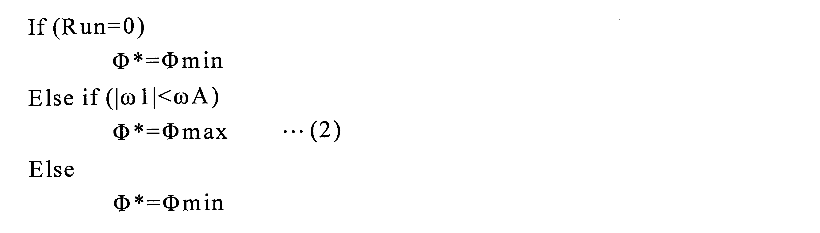
ここに、Φminは可変磁束電動機101として取り得る最小磁束量(>0)、Φmaxは可変磁束電動機101として取り得る最大磁束量、ωAは所定の回転周波数である。尚、磁束量のΦmin,Φmaxの設定については、後で可変磁束制御部113のところで説明する。
電流基準演算部111では、トルク指令Tm*と磁束指令Φ*とを入力として、d軸電流基準IdRとq軸電流基準IqRを次式(3),(4)のように演算する。

同(3),(4)式は、電動機のリラクタンストルクを用いないことを想定し、電動機極数も0とした演算式である。d軸インダクタンスLdとq軸インダクタンスLqの差異ΔLがある突極形電動機であっても、差異のない非突極形の電動機であってもよい。
しかしながら、効率の最適化や所定電流での最大出力を考える場合、リラクタンストルクを考慮することが有効である。この場合、例えば、次式のように演算する。

ここに、Kはd軸電流とq軸電流との比率であり、前述の効率最適化や最大出力等、用途によって変わる値である。最適化を図るためには関数形をとり、その引数としてトルク、速度等を用いる。また、簡易な近似やテーブル化して用いることもできる。また、(5)式の磁束指令Φ*は、後述する磁束推定値Φhを用いても、動作は可能である。
磁化要求生成部129の詳細な構成を図10に示す。この図10のブロックは、制御マイコンによって所定時間ごとに制御がなされる。磁束指令Φ*は、前回値の保持部131に入力され、その値が保持される。前回値の保持部131の出力は、前回に記憶した磁束指令Φ*であり、今回の磁束指令値Φ*と共に、変化判定部130に入力される。変化判定部130では、入力2つの変化があった場合には1を、変化がない場合には0を出力する。すなわち、磁束指令Φ*が変化した場合にのみ1が立つ。上記同様な回路を、磁束指令Φ*に代わり、運転状態フラグRunについても有し、前回値の保持部133に入力され、その値が保持される。前回値の保持部133の出力は、前回に記憶した運転状態フラグRunであり、今回の運転状態フラグRunと共に変化判定部134に入力される。2つの変化判定部130,134の出力が論理和演算部(OR)132に入力され、それらの論理和が磁化要求フラグFCreqとして出力される。
磁化要求生成部129の出力である磁化要求フラグFCreqは、磁束指令Φ*が変化した場合、あるいは、運転状態フラグRunが変化した場合に磁化要求(FCreq=1)となり、それ以外では要求なし(FCreq=0)となる。尚、運転状態フラグRunが変化する状態とは、インバータが始動するとき、停止するとき、保護で停止するときなどである。また、ここでは磁束指令Φ*を用いているが、後述する可変磁束制御部113の磁化電流指令Im*(磁化電流テーブル127の出力)の変化で磁化要求FCreqを生成してもよい。
可変磁束制御部113の詳細な構成を図11に示す。可変磁束制御部113は、磁束指令演算部112の出力である磁束指令Φ*を入力し、d軸電流基準IdRを補正するd軸磁化電流差分量ΔIdm*を出力する。この磁化電流差分量ΔIdm*の生成は、以下の演算処理による。
可変磁石VMGを磁化するためには、図9の可変磁石のBH特性に則り、所定の磁化電流指令Im*を求めればよい。特に、磁化電流指令Im*の大きさは、図9中のH1sat以上、すなわち、可変磁石の磁化飽和領域となるように設定する。
磁化飽和領域まで磁化電流を流すため、磁束指令演算部112で設定すべき磁束量ΦminやΦmaxは、可変磁石の磁束(磁束密度)がプラスないしはマイナスの最大(飽和)値に固定磁石分を加算した値として設定する。可変磁石VMGの磁束量の正の最大値をΦvarmax(負の最大値の絶対値は正の最大値と等しいとする)、固定磁石FMGの磁束量をΦfixとすれば、次式である。
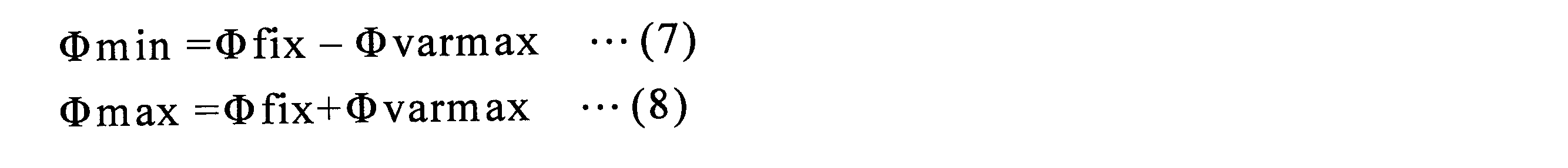
磁束指令Φ*を入力とし、対応する磁化電流を記憶した磁化電流テーブル127によって、磁束指令Φ*を得るための磁化電流指令Im*を出力する。
基本的に、磁石の磁化方向をd軸としているので、磁化電流指令Im*は、d軸電流指令Id*に与えるようにする。本実施の形態では、電流基準演算部111からの出力であるd軸電流基準IdRをd軸磁化電流指令差分ΔIdm*で補正し、d軸電流指令Id*とする構成にしているので、減算器126によってd軸磁化電流指令ΔIdm*を次式によって求める。

尚、磁束切り替えの際には、d軸電流指令Id*に磁化電流Im*を直接与えるような構成とすることも可能である。
一方、磁化要求フラグFCreqは、磁束を切り替えたい要求の際に、少なくとも一瞬切り替え要求(FCreq=1)が立つ。磁束を確実に可変とするために、磁化要求フラグFCreqを最小オンパルス器128へと入力する。この出力である磁化完了フラグ(=1:磁化中、=0:磁化完了)は、一旦オン(=1)が入力された場合、所定の時間の間はオフ(=0)にならない機能を有する。所定時間を越えて入力がオン(=1)である場合には、それがオフとなると同時に出力もオフとなる。
切り替え器123には、磁化完了フラグが入力され、磁化中(磁化完了フラグ=1)の場合には減算器126の出力を、磁化完了(磁化完了フラグ=0)の場合には0を出力する。
電圧指令演算部110は、以上により生成されたdq軸電流指令Id*,Iq*に基づき、当該指令に一致する電流が流れるように電流制御器を含むdq軸電圧指令Vd*,Vq*を生成する。
そして電圧指令演算部110のdq軸電圧指令Vd*,Vq*を、座標変換部105にて3相電圧指令Vu*,Vv*,Vw*に変換し、この3相電圧指令によってPWM回路106がPWMにてゲート信号を生成し、インバータ104をPWM制御する。尚、座標変換部107は電流検出器102の交流検出電流Iu,Iwを2軸dq軸変換してdq軸電流検出値Id,Iqに変換して電圧指令演算部110に入力する。また、擬似微分器108は速度検出器118の信号からインバータ周波数ω1を求める。尚、電圧指令演算部110、座標変換部105,107、PWM回路106には、従来同様の公知技術が採用されている。
図12には、各信号の動作のタイミングチャートの一例が示してある。ここでは保護信号は立っていない状況(PROT=0)だが、運転状態フラグRunの変化及び磁束指令Φ*の変化にて磁化要求フラグが立ち、それを所定時間幅確保する磁化完了フラグが立ち、この磁化完了フラグの期間だけ、磁化電流指令Im*が値を持つ。
次に、このように構成された本実施の形態の永久磁石式回転電機、そしてそのドライブシステムの作用を説明する。1極当りの磁化に要する起磁力は磁化に要する磁界と1極当りの永久磁石の厚みの積で概算する。AlNiCo磁石の第1の永久磁石3は250kA/mの磁界で100%近くまで着磁できる。着磁磁界と1極当りの磁石の厚みの積は、250kA/m×(6×10-3/2)m=750Aとなる。
一方、NdFeB磁石の第2の永久磁石4は1500~2500kA/mの磁界で100%近くまで着磁できる。着磁磁界と1極当りの磁石の厚みの積は、1500~2500kA/m×(2×10-3)m=3000~5000Aとなる。つまり、AlNiCo永久磁石3はNdFeB永久磁石4の約1/4~1/6の磁界で着磁できる。また、AlNiCo永久磁石3を着磁する程度の磁界であれば、NdFeB永久磁石4は可逆減磁状態であり、着磁後でもNdFeB永久磁石4は着磁前の状態の磁束を維持できる。
本実施の形態では、固定子20の電機子巻線21に通電時間が極短時間(1ms~10ms程度)となるパルス的な電流を流して磁界を形成し、AlNiCo永久磁石3に磁界を作用させる。但し、回転電機の巻線インダクタンスの大きさや電流波形により通電時間は変わる。永久磁石を磁化するための磁界を形成するパルス電流は固定子20の電機子巻線21のd軸電流成分とする。着磁磁界を250kA/mとすると、理想的にはAlNiCo永久磁石3には十分な着磁磁界が作用し、NdFeB永久磁石4には着磁による不可逆減磁はない。
図3はAlNiCo永久磁石3とNdFeB永久磁石4の磁束が磁極及びエアギャップ面で加え合せになるように着磁磁界を作用させたときの各永久磁石の磁束を示している。図3ではAlNiCo磁石の第1の永久磁石3とNdFeB磁石の第2の永久磁石4とによる鎖交磁束は増加して増磁状態となる。着磁磁界は固定子20の電機子巻線21に極短時間のパルス的な電流を流して形成する。このとき通電する電流はd軸電流成分である。パルス電流はすぐに0になり、着磁磁界はなくなるが、AlNiCo磁石の第1の永久磁石3は不可逆的に変化して着磁方向に磁束B3を発生する。B4はNdFeB磁石の第2の永久磁石4による磁束である。尚、図3、図4、図5での磁束分布は1極のみを示している。
図4では鎖交磁束を減少させるときの作用を示す。電機子巻線21に負のd軸電流を通電して形成する磁界Bdは図3と逆方向の磁束を発生する。電機子巻線21の負のd軸電流により作られる磁界Bdは、回転子1の磁極中心からAlNiCo永久磁石3とNdFeB永久磁石4とに対して磁化方向とほぼ逆方向に作用している。各永久磁石3,4には図3の磁化方向とは逆方向の磁界B3i,B4iが作用する。AlNiCo永久磁石3は保磁力と磁化方向厚の積を小さくしているため、この逆磁界によりAlNiCo永久磁石3の磁束は不可逆的に減少する。一方、NdFeB永久磁石4は保磁力と磁化方向厚の積が大きいため逆磁界を受けても磁気特性は可逆範囲であり、負のd軸電流による着磁磁界Bdが消えた後の磁化状態には変化がなく磁束量も変わらない。したがって、AlNiCo永久磁石3のみが減磁することになり、鎖交磁束量を減少できる。
本実施の形態ではさらに大きな電流を通電させて強い逆磁界によりAlNiCo永久磁石3の極性を反転させる。AlNiCo永久磁石3の極性を反転させることにより、鎖交磁束を大幅に減少でき、特に鎖交磁束を0にできる特徴がある。
一般にAlNiCo磁石の着磁磁界と1極当りの永久磁石の厚みとの積はNdFeB磁石の約1/4~1/6なので、AlNiCo永久磁石3のみ磁化できる磁界を作用させる。負のd軸電流による磁化(着磁)された後の状態を図5に示す。NdFeB永久磁石4の磁束B4と逆方向に発生するAlNiCo永久磁石3の磁束B3は相殺されて、各永久磁石3,4の磁束量B3,B4が同じ場合ではエアギャップ23の磁束をほぼ0にできる。このとき、NdFeB永久磁石4の磁束B4は相殺されるとともにAlNiCo永久磁石3との磁気回路を構成できるので多くの磁束は回転子1内に分布する。このような作用により、エアギャップ磁束密度の磁束分布は一様に0に分布させることができる。
前述の鎖交磁束が0の状態から鎖交磁束を増加する場合は、鎖交磁束0では逆の極性となっているAlNiCo永久磁石3において、d軸電流による磁界によりAlNiCo永久磁石3の磁束B3を減少させる。このときAlNiCo永久磁石3は逆極性になっているので、AlNiCo永久磁石3に作用させる磁界は図3に示すAlNiCo永久磁石3の元の磁化方向と同方向となる。すなわち、図4に示すd軸電流による磁界Bdとは逆方向になる。さらに鎖交磁束を増加させて元の最大鎖交磁束の状態に戻すときには、AlNiCo永久磁石3は再度極性を反転して(元の極性に戻って)図3の状態に戻る。したがって、本実施の形態の永久磁石式回転電機の場合、AlNiCo永久磁石3は磁気特性上(磁束密度と磁界に関する特性であるB-H曲線)を第1象限から第4象限までの全範囲で動作させることができることになる。
これに対して、従来の永久磁石式回転電機における永久磁石は第2象限のみで動作させている。また、従来の永久磁石式回転電機は、鎖交磁束を低下させるために電機子巻線21の負のd軸電流による磁束を発生させて回転子1の永久磁石4の磁束を相殺させている。しかし、埋め込み磁石電動機では基本波鎖交磁束は50%程度までしか低減できなく、また高調波磁束はかなり増加し、高調波電圧と高調波鉄損が生じて問題となる。したがって、鎖交磁束を0にすることは極めて困難であり、仮に基本波を0にできても高調波磁束は逆にかなり大きな値になる。これに対して、本実施の形態の永久磁石式回転電機では、回転子1において永久磁石3,4のみの磁束で一様に減少できるので高調波磁束は少なく、損失の増加はない。
永久磁石の磁化に関しては、本実施の形態の回転電機においては、d軸電流による磁界はNdFeB永久磁石4には永久磁石2個分(N極とS極の2個の永久磁石)に作用することになり、この点だけでもNdFeB永久磁石4に作用する磁界はAlNiCo永久磁石3に作用する磁界の約半分になる。したがって、本実施の形態の回転電機においては、保磁力と磁化方向厚みの積が小となる第1の永久磁石3は、d軸電流による磁界により磁化され易くなる。
NdFeB永久磁石4は、着磁磁界と磁石の厚みの積がAlNiCo永久磁石3の4倍であり、さらに配置構成の点では、NdFeB永久磁石4に作用するd軸電流による磁界はAlNiCo永久磁石3の1/2になる。したがって、NdFeB永久磁石4を着磁するにはAlNiCo永久磁石3の8倍の起磁力を必要とする。つまり、AlNiCo永久磁石3を着磁する程度の磁界であれば、NdFeB永久磁石4は可逆減磁状態であり、着磁後でもNdFeB永久磁石4は着磁前の状態の磁束を維持できる。
次に、第1の永久磁石であるAlNiCo永久磁石3と第2の永久磁石であるNdFeB永久磁石4の相互的な磁気の影響について述べる。図5の減磁状態ではNdFeB永久磁石4の磁界はAlNiCo永久磁石3にバイアス的な磁界として作用し、負のd軸電流による磁界とNdFeB永久磁石4による磁界がAlNiCo永久磁石3に作用して磁化し易くなる。また、AlNiCo永久磁石3の保磁力と磁化方向厚の積がNdFeB永久磁石4の無負荷時の動作点における磁界の強さと磁化方向厚の積に等しいか、それ以上にすることにより鎖交磁束の増磁状態においてNdFeB永久磁石4の磁界に打ち勝ち、磁束量を発生する。
以上より、本実施の形態の回転電機では、d軸電流によりAlNiCo永久磁石3の鎖交磁束量を最大から0まで大きく変化させることができ、また磁化方向も正逆方向の両方向にできる。NdFeB永久磁石4の鎖交磁束B4を正方向とすると、AlNiCo永久磁石3の鎖交磁束B3を正方向の最大値から0、さらには逆方向の最大値まで広範囲に調整することができる。
以上より、本実施の形態の回転電機では、d軸電流によりAlNiCo永久磁石3の鎖交磁束量を最大から0まで大きく変化させることができ、また磁化方向も正逆方向の両方向にできる。NdFeB永久磁石4の鎖交磁束B4を正方向とすると、AlNiCo永久磁石3の鎖交磁束B3を正方向の最大値から0、さらには逆方向の最大値まで広範囲に調整することができる。
したがって、本実施の形態の永久磁石式回転電機では、AlNiCo永久磁石3をd軸電流で磁化させることによりAlNiCo永久磁石3とNdFeB永久磁石4とを合わせた全鎖交磁束量を広範囲に調整することができる。低速域では、AlNiCo永久磁石3はNdFeB永久磁石4の鎖交磁束と同方向(前述の図3で示した増磁状態)で最大値になるようにd軸電流で磁化する。このとき、永久磁石によるトルクは最大になるので、回転電機のトルク及び出力は最大にすることができる。また、中・高速域では、図4のd軸電流による磁界BdでAlNiCo永久磁石3の磁束量を不可逆的に低下させ、全鎖交磁束量を下げる。これにより回転電機の電圧は下がるので、電源電圧の上限値に対して余裕ができ、回転速度(周波数)をさらに高くすることが可能となる。最高速度を著しく高くするとき(可変速範囲をさらに拡大、例えば基底速度の3倍以上の可変速運転の範囲)はAlNiCo永久磁石3はNdFeB永久磁石4の鎖交磁束と逆方向になるように磁化させる(AlNiCo永久磁石3の磁束B3の向きは図5の状態で磁化は最大とする)。永久磁石3,4の全鎖交磁束は、NdFeB永久磁石4とAlNiCo永久磁石3との鎖交磁束の差となり、最も小さくできる。回転電機の電圧も最小となるので回転速度(周波数)を最高値まで上げることができる。
これらにより、本実施の形態の永久磁石式回転電機及びそれを回転駆動する永久磁石電動機ドライブシステムによれば、高出力で低速回転から高速回転まで広範囲の可変速運転が実現できる。また、本実施の形態の永久磁石式回転電機によれば、鎖交磁束を変化させるときの着磁電流を極短時間だけ流すので損失を著しく低減でき、広い運転範囲で高効率となる。
次に、本実施の形態の永久磁石式回転電機及び永久磁石電動機ドライブシステムにおいて、トルク発生時の負荷電流(q軸電流)による永久磁石3,4の減磁について述べる。本実施の形態の永久磁石式回転電機がトルクを発生するときは、固定子20の電機子巻線21にq軸電流を流すことにより、q軸電流と永久磁石3,4の磁束との磁気作用でトルクを発生させる。このときq軸電流による磁界が発生する。そこで、本実施の形態の永久磁石式回転電機では、AlNiCo永久磁石3は、その磁化方向がq軸方向と直角方向となるようにq軸近傍に配置する。これよりAlNiCo永久磁石3の磁化方向とq軸電流による磁界とが理想的には直交する方向になり、q軸電流による磁界の影響を大きく受けることがなくなる。
しかし、最大トルク状態や小型・高出力化のため電機子巻線のアンペアターンを大きくした回転電機では、負荷電流であるq軸電流で生じる磁界はかなり大きくなる。保磁力と厚みの積が小さい第1の永久磁石を回転子に設けた場合、この過大なq軸電流による磁界はq軸にある永久磁石を不可逆減磁させる。すなわち、q軸電流でトルク発生時に永久磁石が減磁してトルクが低下する。
そこで、本実施の形態の永久磁石式回転電機では、大きなトルクを発生するときは、正のd軸電流をq軸電流に重畳させて流す。図6にトルク発生時に正のd軸電流を重畳させたときの磁界の作用を模式的に示す。図6において、B3iは正のd軸電流による磁界を示し、B5iは負荷電流(q軸電流)により磁界を示し、B6は保磁力と磁化方向厚みの積が小さい第1の永久磁石3の磁化方向を示している。トルクが大きな範囲では各磁極にある2種類の永久磁石3,4は加え合せの方向とするので、この状態では正のd軸電流は永久磁石3の磁化方向と同方向になる。したがって、図6に示すように永久磁石3内でもq軸電流による減磁界を相殺するように正のd軸電流が作る磁界B3iが作用する。このため、本実施の形態を適用すれば、保磁力と厚みの積が小さい第1の永久磁石3を用いても、大きなトルクを発生する状態においても前述の永久磁石3の不可逆減磁を抑制でき、負荷電流の磁界B5iによるトルクの低下を抑制でき、大トルクを発生することが可能となる。
次に、永久磁石3,4の両端部に形成した空洞5の作用について述べる。この空洞5は、永久磁石3,4による遠心力が回転子鉄心2に作用した時の回転子鉄心2への応力集中と減磁界を緩和する。図1に示したような空洞5を設けることにより、回転子鉄心2は曲率のついた形状にでき、応力が緩和される。また、電流による磁界が永久磁石3,4の角部に集中して減磁界が作用し、角部が不可逆減磁する場合がある。ところが本実施の形態では、永久磁石3,4の各端部に空洞5を設けているため、永久磁石端部での電流による減磁界が緩和される。
次に、本実施の形態における回転子1の構造的強度について述べる。本実施の形態における回転子1では、回転子鉄心2内にAlNiCo永久磁石3とNdFeB永久磁石4とを埋め込み、回転子鉄心2で永久磁石3,4を固定している。さらに高速回転時の遠心力に十分に耐え得るようにするため、磁極鉄心部7の中央にボルト穴6を設けて、ボルトで回転子鉄心2を締め付けて回転子端版とシャフトに固定できるようにしている。
これにより、本実施の形態の永久磁石式回転電機及び永久磁石電動機ドライブシステムによれば、次の効果が得られる。NdFeB永久磁石4の鎖交磁束を正方向とすると、AlNiCo永久磁石3の鎖交磁束を正方向の最大値から0まで変化させ、さらには極性を反転して逆方向の最大値まで広範囲に調整することができる。このようにAlNiCo永久磁石3は磁気特性上で第1象限から第4象限までの全範囲で動作させることになる。これらより、本実施の形態では、AlNiCo永久磁石3をd軸電流で磁化させることによりAlNiCo永久磁石3とNdFeB永久磁石4とを合わせた全鎖交磁束量を広範囲に調整することができる。さらに、永久磁石の全鎖交磁束量の調整は回転電機の電圧を広範囲に調整することを可能とし、また、着磁は極短時間のパルス的な電流で行うので常時弱め磁束電流を流し続ける必要がなく、損失を大幅に低減できる。また、従来のように弱め磁束制御を行う必要がないので、高調波磁束による高調波鉄損も発生しない。
以上より、本実施の形態の永久磁石式回転電機及び永久磁石電動機ドライブシステムは、高出力で低速から高速までの広範囲の可変速運転が可能であり、広い運転範囲において高効率なものになる。また、永久磁石による誘導電圧に関しては、AlNiCo永久磁石3をd軸電流で着磁して永久磁石3,4の全鎖交磁束量を小さくできるので、永久磁石の誘導電圧によるインバータ電子部品の破損がなくなり、信頼性が向上する。また、回転電機が無負荷で連れ回される状態では、AlNiCo永久磁石3を負のd軸電流で着磁することで永久磁石3,4の全鎖交磁束量を小さくでき、これより、誘導電圧は著しく低くなり、誘導電圧を下げるための弱め磁束電流を常時通電する必要がほとんどなくなり、総合効率が向上する。特に惰行運転時間が長くなる通勤電車に本実施の形態の永久磁石式回転電機を搭載して駆動すると、総合運転効率は大幅に向上する。
また、本実施の形態の永久磁石式回転電機及び永久磁石電動機ドライブシステムでは、保磁力と磁化方向厚の積が大きい第2の永久磁石4はNdFeB磁石とし、保磁力と磁化方向厚の積が小さい第1の永久磁石3はAlNiCo磁石で構成し、第2の永久磁石4の磁束密度ψPM2は、回転子1の回転速度が最高回転速度ωになったときの第2の永久磁石4による逆起電圧が当該回転電機の電源であるインバータ電子部品の耐電圧E以下になる大きさ、つまり、ψPM2≦E/ω・N(ただし、Nは電機子巻線21の巻数)としている。これにより、次のような効果がある。すなわち、永久磁石による逆起電圧は回転速度に比例して高くなる。この逆起電圧はd軸電流を常時流し続けることによりインバータ電子部品の耐電圧や電源電圧以下に押さえ込まれている。しかし、制御不能時にはこの逆起電圧が過大になりインバータの電子部品等を絶縁破壊する。そのため、従来の永久磁石式回転電機では設計時に耐電圧により永久磁石の逆起電圧が制限され、永久磁石の磁束量が削減され、電動機の低速域での出力及び効率が低下していた。ところが、本実施の形態の場合、高速回転時になると短時間のd軸電流により減磁方向の磁界を発生させて永久磁石を不可逆的に磁化させて永久磁石3,4の鎖交磁束を低減させるので、高速回転時において制御不能になっても、過大な逆起電圧が発生することはない。
また、電機子巻線21等の電気的な短絡が生じた場合は、短絡電流によりAlNiCo永久磁石3は減磁するか極性が反転するので、永久磁石3,4による鎖交磁束はNdFeB永久磁石4によるもののみか極性反転時には0にできる。したがって、短絡電流は瞬時に回転電機自身で小さくできる。これより、短絡電流によるブレーキ力や短絡電流による加熱を防ぐことができる。
以上より、本実施の形態の永久磁石式回転電機及び永久磁石電動機ドライブシステムは、低速回転時で高トルク(高出力)を発生し、また高出力で低速から高速までの広範囲の可変速運転が可能であり、広い運転範囲において高効率運転が可能である。さらに高速回転時の逆起電圧を抑制でき、インバータを含めたドライブシステムの信頼性を高めることができる。
[第2の実施の形態]
本発明の第2の実施の形態について、図1を用いて説明する。本実施の形態の永久磁石式回転電機において、AlNiCo磁石の第1の永久磁石3は磁化方向厚みが一定でない形状とし、図1に示すように断面は台形形状としている。
本発明の第2の実施の形態について、図1を用いて説明する。本実施の形態の永久磁石式回転電機において、AlNiCo磁石の第1の永久磁石3は磁化方向厚みが一定でない形状とし、図1に示すように断面は台形形状としている。
AlNiCo磁石は残留磁束密度が高く保磁力が小さいため磁束密度が低い領域では磁界に対して磁束密度が急変する。したがって、磁界の強さのみで磁束密度を微調整するには磁界の強さの制御は高い精度が要求される。そこで、本実施の形態では永久磁石の着磁に必要な磁化力は永久磁石の磁化方向厚みにより大きく変化することを応用する。本実施の形態では、AlNiCo永久磁石3は台形形状なので磁化方向厚みが一定でない。そのため、着磁磁界を作用させたときに各厚みの永久磁石部分で発生する磁束量を変えることができる。すなわち、着磁磁界の強さは永久磁石の厚みによる影響に大きく依存させることができる。これにより、d軸電流による磁界に対する磁束量の調整も容易になり、外部条件変動による磁束量のばらつきを少なくできる。
[第3の実施の形態]
本発明の第3の実施の形態の永久磁石式回転電機及び永久磁石電動機ドライブシステムについて説明する。本実施の形態は、図1に示した永久磁石式回転電機101に対して図7に示した永久磁石電動機ドライブシステムにより短時間のd軸電流によるパルス的な磁界でAlNiCo永久磁石3を不可逆的に磁化して鎖交磁束量を変化させる。さらに、中速度回転域や高速度回転域で負のd軸電流による磁束を常時発生させることにより、負のd軸電流による磁束と永久磁石3,4による磁束からなる鎖交磁束は、前述の負のd軸電流による磁束で微調整することができる。すなわち、中・高速度域では、短時間のd軸電流によるパルス的な磁界でAlNiCo永久磁石3の磁化状態を不可逆的に変化させることによって鎖交磁束量を大きく変化させ、常時通電させる負のd軸電流により鎖交磁束量を微調整する。このとき、常時通電する負のd軸電流が微調整する鎖交磁束量は僅かなので、常時流し続ける負のd軸電流は僅かとなり、大きな損失は発生しない。
本発明の第3の実施の形態の永久磁石式回転電機及び永久磁石電動機ドライブシステムについて説明する。本実施の形態は、図1に示した永久磁石式回転電機101に対して図7に示した永久磁石電動機ドライブシステムにより短時間のd軸電流によるパルス的な磁界でAlNiCo永久磁石3を不可逆的に磁化して鎖交磁束量を変化させる。さらに、中速度回転域や高速度回転域で負のd軸電流による磁束を常時発生させることにより、負のd軸電流による磁束と永久磁石3,4による磁束からなる鎖交磁束は、前述の負のd軸電流による磁束で微調整することができる。すなわち、中・高速度域では、短時間のd軸電流によるパルス的な磁界でAlNiCo永久磁石3の磁化状態を不可逆的に変化させることによって鎖交磁束量を大きく変化させ、常時通電させる負のd軸電流により鎖交磁束量を微調整する。このとき、常時通電する負のd軸電流が微調整する鎖交磁束量は僅かなので、常時流し続ける負のd軸電流は僅かとなり、大きな損失は発生しない。
これらより、本実施の形態の永久磁石式回転電機によれば、電圧の基になる鎖交磁束量を広範囲で変化させるとともに微調整することができ、しかも高効率で可変できる。
[第4の実施の形態]
本発明の第4の実施の形態の永久磁石式回転電機について、図13を用いて説明する。本実施の形態において、固定子20の構造は、図1に示した第1の実施の形態のものや図20に示した従来例のものと同様である。
本発明の第4の実施の形態の永久磁石式回転電機について、図13を用いて説明する。本実施の形態において、固定子20の構造は、図1に示した第1の実施の形態のものや図20に示した従来例のものと同様である。
図13に示したように、本実施の形態では、回転子1において、その外周側に凸になるように逆U字形状のNdFeB永久磁石4を回転子鉄心2内に埋め込み、逆U字の中心軸がd軸と一致する位置としている。q軸上にはAlNiCo永久磁石3を径方向に回転子鉄心2内に配置している。逆U字形状にすることにより2個のAlNiCo永久磁石3に挟まれた領域でNdFeB永久磁石4の磁極の面積を広くすることができる。さらに、逆U字状にすることによりq軸磁束の磁路Bqを妨げるように逆U字形状のNdFeB永久磁石4を配置するので、q軸インダクタンスを低減できる。これより力率を向上できる。また、逆U字形状のNdFeB永久磁石4の外周側先端(中央部)と回転子鉄心2の外周(エアギャップ面)の間隔WpをAlNiCo永久磁石3とNdFeB永久磁石4の磁束でほぼ磁気飽和しない程度にする。この磁極鉄心7の中央部の磁束密度が最大でも1.9T程度にすれば、エアギャップの磁束分布が歪まなく、永久磁石の磁束を有効に利用できる。
[第5の実施の形態]
本発明の第5の実施の形態の永久磁石式回転電機について、図14を用いて説明する。本実施の形態の永久磁石式回転電機における固定子20の構造は、図1に示した第1の実施の形態のものや図20に示した従来例のものと同様である。
本発明の第5の実施の形態の永久磁石式回転電機について、図14を用いて説明する。本実施の形態の永久磁石式回転電機における固定子20の構造は、図1に示した第1の実施の形態のものや図20に示した従来例のものと同様である。
図14に示したように、本実施の形態における回転子1では、AlNiCo磁石の第1の永久磁石3はq軸で径方向に回転子鉄心2内に配置し、NdFeB磁石の第2の永久磁石4は周方向に接するようにd軸に直角に回転子鉄心2内に配置している。回転子1は回転子鉄心2の内周側で鉄のシャフト9に嵌め込む構成である。シャフト9は4面をカットした形状とし、回転子鉄心2とシャフト9との間には空気層8を形成している。またシャフト9はステンレススティールのような非磁性材とすることができる。
永久磁石を磁化させるための電機子巻線21の電流による磁界は、AlNiCo永久磁石3とNdFeB永久磁石4に作用し、図14の矢印B13,B14のように電流による磁束が流れる。前述の空気層8があるので電流による磁束はシャフト9には通らずにNdFeB永久磁石4,4間の内周側の狭い鉄心部分を通ろうとする。しかし、この狭い鉄心部分は容易に磁気飽和するため、電機子電流による磁界で生じるNdFeB永久磁石4を通る磁束を少なくすることができる。
このように磁化させたいAlNiCo永久磁石3の電流による磁束は増加し、同時にNdFeB永久磁石4を通る電流による磁束は少なくなることにより、回転子磁極鉄心部7及び固定子鉄心22の磁気飽和も緩和される。したがって、AlNiCo永久磁石3を磁化させるためのd軸電流を少なくすることができる。ここで、シャフト9を非磁性材にすると、シャフト9に漏れる磁束も減少してNdFeB永久磁石4を通る磁束はさらに減少し、回転子磁極鉄心部7及び固定子鉄心22の磁気飽和もいっそう緩和される。
[第6の実施の形態]
本発明の第6の実施の形態について説明する。本実施の形態は、第1~5の実施の形態の永久磁石式回転電機において、回転子1における保磁力と磁化方向厚の積が大きい第2の永久磁石4として、Dy元素が少ないNdFeB磁石で構成する。Dy元素が少ないため残留磁束密度は高くなり、20℃において1.3T以上の残留磁束密度が得られる。
本発明の第6の実施の形態について説明する。本実施の形態は、第1~5の実施の形態の永久磁石式回転電機において、回転子1における保磁力と磁化方向厚の積が大きい第2の永久磁石4として、Dy元素が少ないNdFeB磁石で構成する。Dy元素が少ないため残留磁束密度は高くなり、20℃において1.3T以上の残留磁束密度が得られる。
従来の回転電機は高速になると誘導電圧による電圧上昇を抑制するために負のd軸電流による弱め磁束制御を行っている。このとき永久磁石には過大な逆磁界が作用して永久磁石は不可逆減磁して出力が大幅に低下したままになる場合もある。この対策としてNdFeB磁石の中でも保磁力の大きな磁石を適用する。NdFeB磁石の保磁力を大きくする方法としてDy元素を添加するが、これにより永久磁石の残留磁束密度が低下して回転電機の出力も低下する。また、耐減磁を向上させるためにだけNdFeB磁石の磁化方向厚を厚くすることになる。
本実施の形態の永久磁石式回転電機では、AlNiCo永久磁石3を不可逆的に磁化させて電圧となる鎖交磁束量を調整している。したがって、NdFeB永久磁石4に過大な逆磁界が作用するような弱め磁束制御は使用しない。微調整のための弱め制御を使用する場合もあるが、僅かな電流なので逆磁界も極めて小さくできる。これより、本実施の形態の回転電機は、従来の回転電機には減磁のため使用できなかった低保磁力で高残留磁束密度のNdFeB磁石を適用することができるようになり、NdFeB磁石によるエアギャップ磁束密度は高くなり、高出力が得られる。
例えば、従来の回転電機に適用するNdFe磁石の特性は保磁力Hcj=2228kA/m、残留磁束密度Br=1.23Tであり、本発明に実施の形態に適用するNdFeB磁石の特性はHcj=875kA/m、残留磁束密度Br=1.45Tである。このように保磁力は小さいが磁束密度は1.17倍の磁石の適用が可能となり、約1.17倍に高出力が期待できる。
また、従来の回転電機では出力に貢献せずに耐減磁のために磁石の厚みを増加していたが、本実施の形態の回転電機は減磁界が小さいのでNdFeB磁石の使用量を低減できる。また、埋蔵量の少ないDy元素をほとんど添加しないNdFeB磁石を適用できようになるので、将来的にも安定して製造できる。
[第7の実施の形態]
本発明の第7の実施の形態の永久磁石式回転電機では、回転子1における保磁力と磁化方向厚の積が大きい第2の永久磁石4はNdFeB磁石とし、保磁力と磁化方向厚の積が小さい第1の永久磁石3はAlNiCo磁石で構成する。そして、最高回転速度時において、NdFeB永久磁石4が発生する逆起電圧が回転電機の電源であるインバータ電子部品の耐電圧以下にする構成とする。
本発明の第7の実施の形態の永久磁石式回転電機では、回転子1における保磁力と磁化方向厚の積が大きい第2の永久磁石4はNdFeB磁石とし、保磁力と磁化方向厚の積が小さい第1の永久磁石3はAlNiCo磁石で構成する。そして、最高回転速度時において、NdFeB永久磁石4が発生する逆起電圧が回転電機の電源であるインバータ電子部品の耐電圧以下にする構成とする。
永久磁石による逆起電圧は回転速度に比例して高くなる。この逆起電圧がインバータの電子部品に印加し、電子部品の耐電圧以上になると電子部品が絶縁破壊する。そのため、従来の永久磁石回転電機では設計時に耐電圧により永久磁石の逆起電圧が制限され、永久磁石の磁束量が削減され、電動機の低速域での出力及び効率が低下する。
本実施の形態では、高速回転時になると負のd軸電流により減磁方向の磁界で永久磁石を不可逆的に磁化させてAlNiCo永久磁石3の磁束を0近傍まで小さくする。AlNiCo永久磁石3による逆起電圧はほぼ0にできるので、磁束量を調整できないNdFeB永久磁石4による逆起電圧を最高回転速度で耐電圧以下にすればよい。すなわち、NdFeB永久磁石4のみの磁束量を耐電圧以下までになるまで小さくすることになる。一方、低速回転時では、最大の磁束量となるように磁化されたAlNiCo永久磁石3とNdFeB永久磁石4による鎖交磁束量は増加できる。
さらには、実用上では、最高速域ではAlNiCo永久磁石3は低速時とは逆方向に磁化されることになるので、総鎖交磁束量はNdFeB永久磁石4のみの鎖交磁束よりも小さくなる。すなわち、本実施の形態の回転電機においては、高速時の逆起電圧はNdFeB永久磁石4のみによる逆起電圧よりも小さくなり、実質的には耐電圧と許容最高回転数は十分な余裕ができる。
以上より、本実施の形態の回転電機は、低速回転時での高出力と高効率を維持しながら、高速回転時の逆起電圧を抑制でき、インバータを含めたシステムの信頼性を高めることができる。
[第8の実施の形態]
本発明の第8の実施の形態の永久磁石式回転電機について、図15を用いて説明する。本実施の形態の永久磁石式回転電機における固定子20の構造は、図1に示した第1の実施の形態のものや図20に示した従来例のものと同様である。
本発明の第8の実施の形態の永久磁石式回転電機について、図15を用いて説明する。本実施の形態の永久磁石式回転電機における固定子20の構造は、図1に示した第1の実施の形態のものや図20に示した従来例のものと同様である。
本実施の形態の永久磁石式回転電機では、磁極間の中心軸になるq軸と一致する回転子1の半径方向にAlNiCo永久磁石3を回転子鉄心内に配置する。そして、AlNiCo永久磁石3の端部の鉄心を除いたq軸近傍のエアギャップ側回転子鉄心2を回転子鉄心の最外周より窪ませた形状10とする。
次に、本実施の形態の永久磁石式回転電機の作用について述べる。d軸方向の電流の磁束(d軸磁束)はAlNiCo永久磁石3とNdFeB永久磁石4を横断することになり、永久磁石は空気の透磁率とほぼ等しいのでd軸インダクタンスは小さくなる。一方、q軸方向の磁束は回転子鉄心の磁極鉄心7をAlNiCo永久磁石3とNdFeB永久磁石4の長手方向に沿うように流れる。鉄心の磁極鉄心7の透磁率は永久磁石の1000~10000倍あるので、q軸方向の回転子鉄心2に窪みがなく回転子鉄心外径が周方向で均一であれば、q軸インダクタンスは大きくなる。そして、電流と磁束の磁気的作用でトルクを発生するためにq軸電流を流すが、q軸インダクタンスは大きいのでq軸電流で生じる電圧は大きくなる。すなわち、q軸インダクタンスが大きくなることにより、力率が悪くなる。
本実施の形態では、AlNiCo永久磁石3のあるq軸近傍のエアギャップ側回転子鉄心は回転子鉄心2の最外周より窪んだ鉄心の形状10となっているので、窪んだ鉄心部分10を通る磁束は減少する。すなわち、窪んだ鉄心部分10はq軸方向にあるのでq軸インダクタンスを小さくすることができる。これより、力率を向上できる。また、窪んだ鉄心部分10によりAlNiCo永久磁石3の端部近傍では等価的にエアギャップ長が長くなるので、AlNiCo永久磁石3の端部近傍の平均的な磁界は低くなる。これより、トルクを発生するために必要なq軸電流によるAlNiCo永久磁石3への減磁界の影響を小さくできる。
また、AlNiCo永久磁石3の端部と回転子の磁極鉄心7の中央までの間において、d軸中心となる回転子の磁極鉄心7の中央部が回転子の最外周部分となり、磁極鉄心7の中央部から前記AlNiCo永久磁石3の端部の外周側鉄心部分に至るにつれて、回転子の軸中心からの回転子鉄心外周までの距離が短くなる形状とする。
これにより、本実施の形態によってq軸インダクタンスを小さくでき、q軸電流によるAlNiCo永久磁石3の減磁を抑制できる。全周に渡って滑らかに外周の窪みが大きくなっているので磁束の高調波成分を低減できて、トルクリプル、コギングトルクも低減できる。
[第9の実施の形態]
本発明の第9の実施の形態としての永久磁石式回転電機について、図16を用いて説明する。図16は本実施の形態の永久磁石式回転電機の構造を示していて、固定子20の内部に回転子1をエアギャップ23を介して対向するように収容した構造である。固定子20は、従来例と同様であり図20と同様のものである。また、図1に示した第1の実施の形態の永久磁石式回転電機と共通する要素については共通の符号を付して示し、重複する説明は省略する。
本発明の第9の実施の形態としての永久磁石式回転電機について、図16を用いて説明する。図16は本実施の形態の永久磁石式回転電機の構造を示していて、固定子20の内部に回転子1をエアギャップ23を介して対向するように収容した構造である。固定子20は、従来例と同様であり図20と同様のものである。また、図1に示した第1の実施の形態の永久磁石式回転電機と共通する要素については共通の符号を付して示し、重複する説明は省略する。
図16に示すように、本実施の形態の永久磁石式回転電機は、第1の実施の形態に対して回転子1に埋め込んだ保磁力と磁化方向厚みの積が小となる第1の永久磁石3の構成に特徴があり、この第1の永久磁石3を2種類、つまり、径方向の外側に配置した永久磁石3Aと径方向の内側に配置した永久磁石3Bとで構成している。永久磁石3Aは永久磁石3Bに対して、保磁力と磁化方向厚の積がやや大となる磁気特性を有している。例えば永久磁石3AはAlNiCo磁石とし、永久磁石3BはFeCrCo磁石を用いる。あるいは、永久磁石3A,3B共にAlNiCo磁石とするが、磁気特性が上記のように若干異なり、外側に配置した永久磁石3Aは内側に配置した永久磁石3Bよりも保磁力と磁化方向厚の積がやや大となる磁気特性を備えたものとする。尚、その他の構成、またドライブシステムの構成はすべて第1の実施の形態と同様である。
第1の実施の形態に示すように保磁力と磁化方向厚の積が小となる第1の永久磁石3を1種類で構成した場合、通常の回転駆動用の磁界による磁束Bsが常に第1の永久磁石3の磁極側の径方向の外側の肩部分(丸で囲んだ部分S)に強く作用し、磁化電流を流さない状態でも減磁する現象が発生することがある。そこで、本実施の形態の永久磁石式回転電機では、磁化電流を流すことで減磁させ、あるいは磁化方向を反転させる第1の永久磁石3を図示のように2種類の永久磁石3A,3Bにて構成し、主に磁化電流により減磁させ、あるいは磁化方向を反転させる永久磁石は主に永久磁石3Bとし、回転駆動時に作用する強い磁界に対して減磁耐性を持たせるためにその磁界が強く作用する部分Sには保磁力と磁化方向厚の積が永久磁石3Aよりも若干大きい永久磁石3Bを配置する構成にしている。
これにより、本実施の形態の永久磁石式回転電機では、第1の実施の形態の永久磁石式回転電機よりも低速回転時で高トルク(高出力)を発生し、また高出力で低速から高速までの広範囲の可変速運転が可能であり、広い運転範囲において高効率運転が可能である作用、効果を奏する。
尚、上記実施の形態のように第1の永久磁石を保磁力の異なる2種類あるいはそれ以上の複数種の永久磁石にて分割した構造とする構成は、第1の実施の形態で採用した第1の永久磁石3にとどまらず、図13~図16に示したそれぞれの構造の永久磁石式回転電機においても、それらの第1の永久磁石3を本実施の形態と同様の分割構造とすることができる。
[第10の実施の形態]
本発明の第10の実施の形態の永久磁石式回転電機は、上記第1~9の実施の形態のそれぞれにおいて、回転子1を固定子に挿入して組み立てる製造時に、AlNiCo永久磁石3による磁束とNdFeB永久磁石4による磁束が、磁極鉄心7又はエアギャップ面で互いに逆方向となるようにAlNiCo永久磁石3を磁化させた状態にすることを特徴とする。
本発明の第10の実施の形態の永久磁石式回転電機は、上記第1~9の実施の形態のそれぞれにおいて、回転子1を固定子に挿入して組み立てる製造時に、AlNiCo永久磁石3による磁束とNdFeB永久磁石4による磁束が、磁極鉄心7又はエアギャップ面で互いに逆方向となるようにAlNiCo永久磁石3を磁化させた状態にすることを特徴とする。
製造工程で、着磁した回転子1を固定子に挿入して組立を行うには永久磁石の磁気吸引力に対策が必要である。本発明では、AlNiCo永久磁石3の磁束とNdFeB永久磁石4の磁束が互いに逆方向になるように磁化したので回転子1から発生する永久磁石の磁束量は少なくできる。したがって、回転子と固定子の間で生じる磁気吸引力は小さくなり、組立作業性が向上する。さらに、AlNiCo永久磁石3とNdFeB永久磁石4により発生する磁束量を0にすると、磁気吸引力はなくなり、回転子を固定子に組み込む作業は極めて容易にできる。
尚、上記第1~9の実施の形態のそれぞれにおいて、修理点検のために回転子1を固定子から抜き出す分解時にも、AlNiCo永久磁石3による磁束とNdFeB永久磁石4による磁束が、磁極鉄心7又はエアギャップ面で互いに逆方向となるようにAlNiCo永久磁石3を磁化させた状態にするのが望ましい。分解時に、AlNiCo永久磁石3の磁束とNdFeB永久磁石4の磁束が互いに逆方向になるように磁化しておくと、回転子1から発生する永久磁石の磁束量は少なくでき、回転子と固定子の間で生じる磁気吸引力を小さくでき、分解作業性も向上する。さらに、AlNiCo永久磁石3とNdFeB永久磁石4により発生する磁束量を0にすると、磁気吸引力はなくなり、回転子を固定子から抜き出す作業も極めて容易になる。
また尚、上記の各実施の形態では4極の回転電機を示したが、8極等の多極の回転電機に対しても本発明を適用でき、その場合には、極数に応じて永久磁石の配置位置、形状を適切に変更することで対応するが、作用、効果は各実施の形態と同様に得られる。
また、磁極を形成する永久磁石において、保磁力と磁化方向の厚みの積をもって永久磁石を区別する定義をしている。したがって、磁極には同じ種類の永久磁石で形成し、磁化方向厚みを異なるように形成しても同様な作用と効果が得られる。
[第11の実施の形態]
本発明の第11の実施の形態としての永久磁石電動機ドライブシステム200について、図17~図19を用いて説明する。本実施の形態の永久磁石電動機ドライブシステムは、上記第1の実施の形態のドライブシステムに代えて、第1の実施の形態の永久磁石式回転電機乃至第9の実施の形態の永久磁石式回転電機の駆動制御に適用できる。尚、図17において、図7に示した第1の実施の形態の永久磁石電動機ドライブシステムと共通の要素には同一の符号を付して示してある。
本発明の第11の実施の形態としての永久磁石電動機ドライブシステム200について、図17~図19を用いて説明する。本実施の形態の永久磁石電動機ドライブシステムは、上記第1の実施の形態のドライブシステムに代えて、第1の実施の形態の永久磁石式回転電機乃至第9の実施の形態の永久磁石式回転電機の駆動制御に適用できる。尚、図17において、図7に示した第1の実施の形態の永久磁石電動機ドライブシステムと共通の要素には同一の符号を付して示してある。
本実施の形態の可変磁束永久磁石電動機ドライブシステム200は主回路200Aと制御回路200Bで構成されており、図7に示した第1の実施の形態に対して、制御回路200Bにおいて電圧指令演算部110の出力する電圧指令Vd*,Vq*と座標変換部107の出力するdq軸電流Id,Iqとロータ回転角周波数ω1を用いて磁束Φhを推定し、可変磁束制御部113に出力する磁束推定部109を追加的に備え、また可変磁束制御部113が図19の構成を備えたことを特徴とする。尚、主回路200Aの構成は図7の主回路100Aと同じである。
磁束推定部109は、dq軸電圧指令Vd*,Vq*とdq軸電流Id,Iq、ロータ回転角周波数ω1(インバータ周波数)に基づき、次式によってd軸磁束量を推定する。

磁束推定値Φhは、磁束指令演算部112からの磁束指令Φ*と共に可変磁束制御部113に入力される。
本実施の形態における可変磁束制御部113の詳細な構成を図18に示す。減算器119にて磁束指令Φ*と磁束推定値Φhとの偏差が演算され、同偏差はPI制御器120に入力される。また、磁束指令Φ*は磁化電流基準演算部121に入力される。磁化電流基準演算部121は、磁束指令Φ*に応じた磁束に磁化されるように、磁化電流指令Im*をテーブルを利用して算定し、あるいは関数式に当てはめて算定する。この特性は、前述のBH特性に基づき算定する。加算器122において、磁化電流基準演算部121の出力とPI制御部120の出力とを加算する。
この加算器122が磁化電流指令Im*になる。磁化するためには、この磁化電流指令Im*をd軸電流指令Id*として与える。よって、本実施の形態の構成上、Id*がIm*と一致するように、減算器126にて磁化電流指令Im*からd軸電流基準IdRを減算し、d軸磁化電流指令差分値ΔIdm*を算出する。これにより、図18における加算器114にてd軸電流基準IdRと加算されるため、d軸電流指令Id*が磁化電流Im*と一致する。
可変磁束制御部113における切り替え器123では、後述の磁化完了フラグに基づき、2つの入力を選択して、磁化電流指令Idm*として選択して出力する。磁化完了フラグ=0(磁化完了)の場合、d軸磁化電流指令差分ΔIdm*=0とする。また、磁化完了フラグ=1(磁化中)である場合、加算器122の出力をΔIdm*として出力する。
減算器119の出力である磁束指令Φ*と磁束推定値Φhとの偏差は、磁化完了判定部124へと入力される。この磁化完了判定部124では、例えば磁束偏差の絶対値が所定値αより小さい場合には1を出力し、αより大きい場合には0を出力する。フリップフロップ(RS-FF)125は、セットSへの入力に磁化要求フラグFCreqを、リセットR側に磁化完了判定部124の出力を入力する。このRS-FF125の出力が磁化完了フラグであり、PI制御部120と切り替え器123とに入力される。この磁化完了フラグが0であれば磁化完了、1であれば磁化中であることを示す。
また、磁束推定部109の出力である磁束推定値Φhは電流基準演算部111にも入力される。電流基準演算部111では、第1の実施の形態での演算式での磁束指令Φ*に代え、磁束推定値Φhによってdq軸電流基準IdR,IqRを次式にて求める。

以上の構成により、本実施の形態は、次のような作用効果を奏する。磁化要求があった場合、磁化要求フラグ=1が少なくとも一瞬立つ。RS-FF125がセットされることで、磁化完了フラグ=1、すなわち磁化中になる。切り替え器123がPI制御器120及び磁化電流基準演算部121からの出力を磁化電流指令Im*として出力するようになる。この磁化電流基準演算部121は、磁束指令Φ*に磁化されるように、事前に把握しているBH特性に基づく磁化電流をフィードフォワード的に与えることになる。これにより、指令値の近傍まで瞬時に磁化することができ、磁化に要する時間が低減されるため、不要なトルクの発生や損失の発生を抑えることができる。尚、BH特性は、予め実験的に求めたものを用いることもできる。
しかしながら、前述のように、厳密に磁束を所定値に一致させることは困難である。そこで、本実施の形態では、図19に示すように、可変磁束制御部113におけるPI制御器120の作用により磁束の偏差が0に近づくように磁化電流Im*を補正していく。これにより、最終的には磁束指令Φ*と磁束推定値Φh(すなわち、推定誤差がなければ実磁束)とが一致することになる。このため、磁化処理における磁束量の繰り返しの精度が向上し、トルク精度が向上できる。
また、本実施の形態では、図19に示すように、可変磁束制御部113における磁化完了判定部124で、磁束偏差の絶対値が所定値α以内となったことで事実上磁束は一致し磁化が完了したとして出力を1にし、RS-FF125はこのリセット要求を受けて、出力である磁化完了フラグを0にする。よって、確実に磁束推定値がその指令である磁束指令Φ*に一致したことをもって磁化処理を完了することができる。これにより、本実施の形態によれば、磁化処理における磁束量の繰り返し精度が向上し、トルク精度の向上が期待できる。
また、本実施の形態によれば、dq軸電流基準IdR,IqRの生成に電圧電流より推定された磁束推定値Φhを用いるため、仮に磁化処理によって磁束量にばらつきが生じても実態に応じてdq軸電流指令が補正される。そしてこの指令に応じてdq軸電流が流れるため、可変磁束量のばらつきがトルクに与える影響を低減することが可能であり、トルク精度が向上する。
尚、本実施の形態では、磁束推定値に基づき構成しているが、磁束推定器には、LdやLqなどのモータインダクタンスが含まれる。これらの値は磁気飽和によって変動するが、特に可変磁束モータでは磁気飽和が可変磁束量によって大きく変動する。よって、可変磁束の推定値を入力として、モータインダクタンスを出力する関数あるいはテーブルを備えることは、磁束推定精度、ひいてはトルク精度の向上に有益である。
また、上述のようにテーブル化しても、インダクタンスの特性を精度良く把握することが困難な場合もある。その場合、磁束を推定する代わり、ホール素子などによって構成される磁束検出器を備え、検出された実磁束Φrを上記の磁束推定値Φhの代わりに用いることで、より一層の磁束推定精度の向上、ひいてはトルク精度の向上が図れる。
以上、本発明の実施の形態について説明してきたが、本発明は上記の実施の形態に限定されるものではなく、次のような永久磁石式回転電機や永久磁石電動機ドライブシステムも技術的範囲となる。
(1)異なった磁気特性の第1の永久磁石と第2の永久磁石とを回転子鉄心内にその回転中心に対して対称に埋め込んだ回転子と、前記回転子をその周囲に磁気空隙を介して囲繞するように配置された固定子と、前記固定子の前記磁気空隙に面する内周部に形成された電機子巻線とを有する永久磁石式回転電機であって、前記回転子における第1の永久磁石の磁気特性は、保磁力が100kA/m~300kA/m、残留磁束密度が0.6T以上であり、ヒシテリシス特性の可逆磁化域から不可逆磁化域へ移行するクニック点が0.6T以上にあり、前記回転子における第2の永久磁石の磁気特性は、前記第1の永久磁石よりも保磁力が大きく、残留磁束密度が0.6T以上であり、かつ、前記第1の永久磁石において、その保磁力と磁化方向厚との積が前記第2の永久磁石の無負荷時の動作点における磁界の強さと磁化方向厚との積以上であり、これにより、前記磁極において前記電機子巻線の電流が作る磁界により前記第1の永久磁石を磁化させることで当該第1の永久磁石の磁束量を不可逆的に変化させることができるようにした永久磁石式回転電機において、前記第1の永久磁石の保磁力と磁化方向厚との積を、前記第2の永久磁石の保磁力と磁化方向厚との積よりも小さく、かつ、前記第2の永久磁石の無負荷時の動作点における磁界の強さと磁化方向厚との積以上とした永久磁石式回転電機。
(2)上記の永久磁石式回転電機において、前記第1の永久磁石の磁化方向厚を、前記第2の永久磁石の磁化方向厚よりも大きくした永久磁石式回転電機。
(3)上記の永久磁石式回転電機において、前記第1の永久磁石を、前記電機子巻線の電流が作る磁界により磁化されて極性を反転するものとした永久磁石式回転電機。
(4)上記の永久磁石式回転電機において、前記第1の永久磁石を、前記磁極において前記電機子巻線の電流が作る磁界により磁化されてその磁束量が不可逆的に変化し、すべての永久磁石による電機子巻線の鎖交磁束量が0になるまで変化するものとした永久磁石式回転電機。
(5)上記の永久磁石式回転電機において、前記第1の永久磁石を、前記第2の永久磁石からバイアス的な磁界が作用するように配置した永久磁石式回転電機。
(6)上記の永久磁石式回転電機において、前記第1の永久磁石と第2の永久磁石との磁化方向を異ならせた永久磁石式回転電機。
(7)上記の永久磁石式回転電機において、前記磁極を、前記第1の永久磁石をその磁化方向とq軸のなす角度が前記第2の永久磁石の磁化方向とq軸のなす角度よりも大きくなる位置に配置した永久磁石式回転電機。
(8)上記の永久磁石式回転電機において、前記磁極を、前記第2の永久磁石をその磁化方向がd軸方向又は半径方向になる位置に配置した永久磁石式回転電機。
(9)上記の永久磁石式回転電機において、前記磁極を、前記第1の永久磁石をその磁化方向が周方向になる位置に配置した永久磁石式回転電機。
(10)上記の永久磁石式回転電機において、前記磁極を、前記第2の永久磁石は前記回転子鉄心に埋め込み、当該第2の永久磁石はその中心部が端部よりも前記磁気空隙に近くなる形状とした永久磁石式回転電機。
(11)上記の永久磁石式回転電機において、前記磁極を、前記第2の永久磁石は、その中心部から前記回転子鉄心の磁気空隙面までの間隔を、当該第2の永久磁石の中心部近傍の回転子鉄心が全ての永久磁石の磁束で磁気飽和しない程度の位置に配置した永久磁石式回転電機。
(12)上記の永久磁石式回転電機において、前記第2の永久磁石に磁気回路で直列に配置された磁路の一部を、当該第2の永久磁石の磁束でほぼ磁気飽和する断面積とした永久磁石式回転電機。
(13)上記の永久磁石式回転電機において、前記第2の永久磁石を、20℃において1.3T以上の残留磁束密度を有するものにした永久磁石式回転電機。
(14)上記の永久磁石式回転電機において、前記第2の永久磁石を、Dy元素をほとんど含まないNdFeB系の永久磁石にした永久磁石式回転電機。
(15)上記の永久磁石式回転電機において、前記第2永久磁石の磁束密度ψPM2を、前記回転子の回転速度が最高回転速度ωになったときの前記第2の永久磁石による逆起電圧が当該回転電機の電源であるインバータ電子部品の耐電圧E以下になる大きさ(ψPM2≦E/ω・N。ただし、Nは前記電機子巻線の巻数)にした永久磁石式回転電機。
(16)上記の永久磁石式回転電機において、前記回転子鉄心を、前記回転子の磁極中心軸となるd軸方向の磁気抵抗が小さく、磁極間の中心軸となるq軸方向の磁気抵抗が大きくなる形状にした永久磁石式回転電機。
(17)上記の永久磁石式回転電機において、前記第1の永久磁石を、前記磁気空隙側の端部で磁気抵抗が高くなる構成とした永久磁石式回転電機。
(18)上記の永久磁石式回転電機において、前記第1の永久磁石をq軸近傍に配置し、前記q軸近傍の前記磁気空隙側の回転子鉄心部分を前記回転子鉄心の最外周よりも窪ませた形状とした永久磁石式回転電機。
(19)上記の永久磁石式回転電機において、前記第1の永久磁石をq軸近傍に配置し、d軸中心となる前記回転子鉄心の磁極の中央部を前記回転子の最外周部分とし、前記回転子鉄心において前記d軸中心の磁極中央部近傍から前記q軸近傍に至る部分又はその一部分を当該回転子鉄心の最外周よりも窪ませた形状とした永久磁石式回転電機。
(20)上記の永久磁石式回転電機において、前記第1の永久磁石を、保磁力が異なる2種類の永久磁石で構成されていて、保磁力の大きい方の永久磁石を径方向の外側、保磁力の小さい方の永久磁石を径方向の内側に配置した永久磁石式回転電機。
(21)永久磁石を用いた永久磁石電動機と、前記永久磁石電動機を駆動するインバータと、前記永久磁石の磁束を制御するための磁化電流を流す磁化手段とを備え、前記永久磁石電動機は、異なった磁気特性の第1の永久磁石と第2の永久磁石とを回転子鉄心内にその回転中心に対して対称に埋め込んだ回転子と、前記回転子をその周囲に磁気空隙を介して囲繞するように配置された固定子と、前記固定子の前記磁気空隙に面する内周部に形成された電機子巻線とを有し、前記磁化手段は、前記永久磁石電動機の電機子巻線のd軸電流を短時間流して発生させる磁界により各磁極で前記第1の永久磁石を磁化させて永久磁石の磁束量を不可逆的に変化させ、さらに前記電機子巻線に流す電流の電流位相を変化させることにより磁化電流を流す永久磁石電動機ドライブシステムにおいて、前記回転子における第1の永久磁石の磁気特性は、保磁力が100kA/m~300kA/m、残留磁束密度が0.6T以上であり、ヒシテリシス特性の可逆磁化域から不可逆磁化域へ移行するクニック点が0.6T以上にあり、前記回転子における第2の永久磁石の磁気特性は、前記第1の永久磁石よりも保磁力が大きく、残留磁束密度が0.6T以上であり、かつ、前記第1の永久磁石において、その保磁力と磁化方向厚との積が前記第2の永久磁石の無負荷時の動作点における磁界の強さと磁化方向厚との積以上であり、前記磁極を形成する前記第1の永久磁石と第2の永久磁石とをそれらの磁束が加え合わせになるように配置及び磁化し、前記電機子巻線の電流が作る磁界により前記第1の永久磁石を磁化させて永久磁石による鎖交磁束を不可逆的に減少させ、また減少後に前記電機子巻線の電流が作る磁界を逆方向に発生させて前記第1の永久磁石を磁化させて鎖交磁束量を不可逆的に増加させることを特徴とする永久磁石電動機ドライブシステムにおいて、前記磁極を形成する前記第1の永久磁石と第2の永久磁石とをそれらの磁束が加え合わせになるように配置及び磁化し、前記電機子巻線の電流が作る第1の方向の磁界により前記第1の永久磁石を磁化させてその極性を反転させ、また反転後に前記電機子巻線の電流が作る磁界を前記第1の方向と逆の第2の方向に発生させてさらに前記第1の永久磁石の極性を再反転させて元の極性にするようにした永久磁石電動機ドライブシステム。
(22)上記の永久磁石電動機ドライブシステムにおいて、前記d軸電流による磁界で前記第1の永久磁石を磁化させてその磁束量を不可逆的に変化させるか、前記磁界で前記第1の永久磁石の極性を反転させ、前記第1の永久磁石を磁化するd軸電流を流すと同時にq軸電流によりトルクを制御するようにした永久磁石電動機ドライブシステム。
(23)上記の永久磁石電動機ドライブシステムにおいて、運転時に前記d軸電流による磁界によって前記第1の永久磁石を磁化させてその磁束量を不可逆的に変化させる動作若しくは前記第1の永久磁石の極性を反転させる動作と、前記d軸電流により生じる磁束により電流と永久磁石で生じる電機子巻線の鎖交磁束量とをほぼ可逆的に変化させる動作を有するようにした永久磁石電動機ドライブシステム。
(24)上記の永久磁石電動機ドライブシステムにおいて、最大トルク時には各磁極における第1の永久磁石と第2の永久磁石との磁束が加え合わせになるように前記第1の永久磁石を磁化させ、トルクの小さな軽負荷時、中速回転域及び高速回転域では前記第1の永久磁石は、電流による磁界で磁化させてその磁束を減少させるか又は前記磁界でその極性を反転させるようにした永久磁石電動機ドライブシステム。
Claims (4)
- 異なった磁気特性の第1の永久磁石と第2の永久磁石とを回転子鉄心内にその回転中心に対して対称に埋め込んだ回転子と、前記回転子をその周囲に磁気空隙を介して囲繞するように配置された固定子と、前記固定子の前記磁気空隙に面する内周部に形成された電機子巻線とを有する永久磁石式回転電機であって、
前記回転子における第1の永久磁石の磁気特性は、保磁力が100kA/m~300kA/m、残留磁束密度が0.6T以上であり、ヒシテリシス特性の可逆磁化域から不可逆磁化域へ移行するクニック点が0.6T以上にあり、
前記回転子における第2の永久磁石の磁気特性は、前記第1の永久磁石よりも保磁力が大きく、残留磁束密度が0.6T以上であり、かつ、
前記第1の永久磁石において、その保磁力と磁化方向厚との積が前記第2の永久磁石の無負荷時の動作点における磁界の強さと磁化方向厚との積以上であり、
これにより、前記磁極において前記電機子巻線の電流が作る磁界により前記第1の永久磁石を磁化させることで当該第1の永久磁石の磁束量を不可逆的に変化させることができるようにした永久磁石式回転電機。 - 異なった磁気特性の第1の永久磁石と第2の永久磁石とを回転子鉄心内にその回転中心に対して対称に埋め込んだ回転子と、前記回転子をその周囲に磁気空隙を介して囲繞するように配置された固定子と、前記固定子の前記磁気空隙に面する内周部に形成された電機子巻線とを有する永久磁石式回転電機であって、前記回転子における第1の永久磁石の磁気特性は、保磁力が100kA/m~300kA/m、残留磁束密度が0.6T以上であり、ヒシテリシス特性の可逆磁化域から不可逆磁化域へ移行するクニック点が0.6T以上にあり、前記回転子における第2の永久磁石の磁気特性は、前記第1の永久磁石よりも保磁力が大きく、残留磁束密度が0.6T以上であり、かつ、前記第1の永久磁石において、その保磁力と磁化方向厚との積が前記第2の永久磁石の無負荷時の動作点における磁界の強さと磁化方向厚との積以上であり、これにより、前記磁極において前記電機子巻線の電流が作る磁界により前記第1の永久磁石を磁化させることで当該第1の永久磁石の磁束量を不可逆的に変化させることができるようにした永久磁石式回転電機の組立方法であって、
前記回転子を前記固定子の内側に挿入して組み立てる時に、前記第1の永久磁石による磁束と、前記第2の永久磁石による磁束が前記磁極又は磁気空隙面で互いに逆方向となるように着磁した状態にして組み立てることを特徴とする永久磁石式回転電機の組立方法。 - 異なった磁気特性の第1の永久磁石と第2の永久磁石とを回転子鉄心内にその回転中心に対して対称に埋め込んだ回転子と、前記回転子をその周囲に磁気空隙を介して囲繞するように配置された固定子と、前記固定子の前記磁気空隙に面する内周部に形成された電機子巻線とを有する永久磁石式回転電機であって、前記回転子における第1の永久磁石の磁気特性は、保磁力が100kA/m~300kA/m、残留磁束密度が0.6T以上であり、ヒシテリシス特性の可逆磁化域から不可逆磁化域へ移行するクニック点が0.6T以上にあり、前記回転子における第2の永久磁石の磁気特性は、前記第1の永久磁石よりも保磁力が大きく、残留磁束密度が0.6T以上であり、かつ、前記第1の永久磁石において、その保磁力と磁化方向厚との積が前記第2の永久磁石の無負荷時の動作点における磁界の強さと磁化方向厚との積以上であり、これにより、前記磁極において前記電機子巻線の電流が作る磁界により前記第1の永久磁石を磁化させることで当該第1の永久磁石の磁束量を不可逆的に変化させることができるようにした永久磁石式回転電機の分解方法であって、
前記回転子を前記固定子の内側から抜き取る時に、前記第1の永久磁石による磁束と、前記第2の永久磁石による磁束が前記磁極又は磁気空隙面で互いに逆方向となるように着磁した状態にして抜き取ることを特徴とする永久磁石式回転電機の分解方法。 - 永久磁石を用いた永久磁石電動機と、前記永久磁石電動機を駆動するインバータと、前記永久磁石の磁束を制御するための磁化電流を流す磁化手段とを備え、
前記永久磁石電動機は、異なった磁気特性の第1の永久磁石と第2の永久磁石とを回転子鉄心内にその回転中心に対して対称に埋め込んだ回転子と、前記回転子をその周囲に磁気空隙を介して囲繞するように配置された固定子と、前記固定子の前記磁気空隙に面する内周部に形成された電機子巻線とを有し、
前記磁化手段は、前記永久磁石電動機の電機子巻線のd軸電流を短時間流して発生させる磁界により各磁極で前記第1の永久磁石を磁化させて永久磁石の磁束量を不可逆的に変化させ、さらに前記電機子巻線に流す電流の電流位相を変化させることにより磁化電流を流す永久磁石電動機ドライブシステムにおいて、
前記回転子における第1の永久磁石の磁気特性は、保磁力が100kA/m~300kA/m、残留磁束密度が0.6T以上であり、ヒシテリシス特性の可逆磁化域から不可逆磁化域へ移行するクニック点が0.6T以上にあり、
前記回転子における第2の永久磁石の磁気特性は、前記第1の永久磁石よりも保磁力が大きく、残留磁束密度が0.6T以上であり、かつ、
前記第1の永久磁石において、その保磁力と磁化方向厚との積が前記第2の永久磁石の無負荷時の動作点における磁界の強さと磁化方向厚との積以上であり、
前記磁極を形成する前記第1の永久磁石と第2の永久磁石とをそれらの磁束が加え合わせになるように配置及び磁化し、
前記電機子巻線の電流が作る磁界により前記第1の永久磁石を磁化させて永久磁石による鎖交磁束を不可逆的に減少させ、また減少後に前記電機子巻線の電流が作る磁界を逆方向に発生させて前記第1の永久磁石を磁化させて鎖交磁束量を不可逆的に増加させることを特徴とする永久磁石電動機ドライブシステム。
Priority Applications (3)
| Application Number | Priority Date | Filing Date | Title |
|---|---|---|---|
| EP20090711888 EP2246961A1 (en) | 2008-02-21 | 2009-02-16 | Permanent magnet type rotary motor, assembly method for permanent magnet type rotary motor, disassembly method for permanent magnet type rotary motor, and permanent magnet type rotary motor drive system |
| US12/918,715 US8269390B2 (en) | 2008-02-21 | 2009-02-16 | Permanent-magnet-type rotating electrical machine and permanent magnet motor drive system |
| CN2009801055329A CN101946386A (zh) | 2008-02-21 | 2009-02-16 | 永久磁铁式旋转电机、永久磁铁式旋转电机的组装方法、永久磁铁式旋转电机的分解方法以及永久磁铁电动机驱动系统 |
Applications Claiming Priority (2)
| Application Number | Priority Date | Filing Date | Title |
|---|---|---|---|
| JP2008040448A JP2009201259A (ja) | 2008-02-21 | 2008-02-21 | 永久磁石式回転電機、永久磁石式回転電機の組立方法、永久磁石式回転電機の分解方法及び永久磁石電動機ドライブシステム |
| JP2008-040448 | 2008-02-21 |
Publications (1)
| Publication Number | Publication Date |
|---|---|
| WO2009104553A1 true WO2009104553A1 (ja) | 2009-08-27 |
Family
ID=40985434
Family Applications (1)
| Application Number | Title | Priority Date | Filing Date |
|---|---|---|---|
| PCT/JP2009/052536 WO2009104553A1 (ja) | 2008-02-21 | 2009-02-16 | 永久磁石式回転電機、永久磁石式回転電機の組立方法、永久磁石式回転電機の分解方法及び永久磁石電動機ドライブシステム |
Country Status (5)
| Country | Link |
|---|---|
| US (1) | US8269390B2 (ja) |
| EP (1) | EP2246961A1 (ja) |
| JP (1) | JP2009201259A (ja) |
| CN (1) | CN101946386A (ja) |
| WO (1) | WO2009104553A1 (ja) |
Cited By (3)
| Publication number | Priority date | Publication date | Assignee | Title |
|---|---|---|---|---|
| CN103532318A (zh) * | 2013-10-22 | 2014-01-22 | 重庆市灵龙五金有限公司 | 定子自动生产线 |
| JP2016524443A (ja) * | 2013-06-28 | 2016-08-12 | 日産自動車株式会社 | 可変磁化マシン制御装置 |
| WO2020093773A1 (zh) * | 2018-11-08 | 2020-05-14 | 珠海格力电器股份有限公司 | 电机转子结构及永磁电机 |
Families Citing this family (35)
| Publication number | Priority date | Publication date | Assignee | Title |
|---|---|---|---|---|
| EP2048772B1 (en) | 2006-07-24 | 2021-10-20 | Kabushiki Kaisha Toshiba | Variable magnetic flux motor drive system |
| EP2192684B1 (en) * | 2007-09-18 | 2020-07-08 | Kabushiki Kaisha Toshiba | Variable magnetic flux drive system |
| JP5159577B2 (ja) | 2008-11-19 | 2013-03-06 | 株式会社東芝 | 永久磁石式回転電機 |
| JP5056959B2 (ja) * | 2011-01-13 | 2012-10-24 | 三菱マテリアル株式会社 | モータのリサイクル方法 |
| JP5695439B2 (ja) | 2011-02-18 | 2015-04-08 | ルネサスエレクトロニクス株式会社 | 半導体装置 |
| US8928198B2 (en) | 2011-02-28 | 2015-01-06 | Uqm Technologies Inc. | Brushless PM machine construction enabling low coercivity magnets |
| JP5811665B2 (ja) * | 2011-07-28 | 2015-11-11 | トヨタ自動車株式会社 | 回転電気 |
| JP2013135542A (ja) * | 2011-12-27 | 2013-07-08 | Hitachi Ltd | 焼結磁石モータ |
| JP2015510388A (ja) | 2012-03-13 | 2015-04-02 | ブローゼ・ファールツォイクタイレ・ゲーエムベーハー・ウント・コンパニ・コマンディットゲゼルシャフト・ヴュルツブルク | 電気機械 |
| CN104247213B (zh) * | 2012-04-16 | 2018-10-12 | 奥的斯电梯公司 | 永磁电机 |
| JP2014087143A (ja) * | 2012-10-23 | 2014-05-12 | Hitachi Appliances Inc | 永久磁石同期電動機 |
| US20140184005A1 (en) * | 2012-12-31 | 2014-07-03 | Hyundai Motor Company | Rotor for drive motor |
| JP5928988B2 (ja) * | 2013-06-05 | 2016-06-01 | カシオ計算機株式会社 | ロータの製造方法 |
| CN103683697B (zh) * | 2013-12-05 | 2015-10-14 | 张学义 | 切向与径向合成磁场永磁稳压发电机的生产方法 |
| JP6473567B2 (ja) * | 2014-02-28 | 2019-02-20 | 東芝産業機器システム株式会社 | 回転電機 |
| JP6371550B2 (ja) * | 2014-03-26 | 2018-08-08 | 東芝産業機器システム株式会社 | 永久磁石式回転電機 |
| RU2583837C1 (ru) * | 2015-01-12 | 2016-05-10 | Федеральное государственное бюджетное образовательное учреждение высшего профессионального образования "Уфимский государственный авиационный технический университет" | Интегрированный высокотемпературный стартер-генератор и способ управления им |
| JP6539465B2 (ja) | 2015-03-19 | 2019-07-03 | 株式会社東芝 | 横方向磁束型回転電機 |
| JP6792323B2 (ja) * | 2015-05-14 | 2020-11-25 | 株式会社豊田中央研究所 | 磁石を用いた係合システムの着磁制御方法 |
| US10819259B2 (en) | 2017-05-04 | 2020-10-27 | Ge Global Sourcing Llc | Permanent magnet based electric machine having enhanced torque |
| US10516305B2 (en) | 2017-05-23 | 2019-12-24 | Ford Global Technologies, Llc | Variable flux bridge for rotor of an electric machine |
| US10312783B2 (en) | 2017-05-23 | 2019-06-04 | Ford Global Technologies, Llc | Variable flux bridge for rotor an electric machine |
| JP6828723B2 (ja) * | 2017-08-01 | 2021-02-10 | 株式会社デンソー | 磁石の製造方法 |
| US10714988B2 (en) * | 2017-08-24 | 2020-07-14 | Uchicago Argonne, Llc | Permanent magnet design to enable higher magnetic flux density |
| WO2019049392A1 (ja) * | 2017-09-11 | 2019-03-14 | 株式会社 東芝 | 回転電機 |
| CN107994702B (zh) * | 2017-12-21 | 2019-04-30 | 珠海格力电器股份有限公司 | 电机转子和永磁电机 |
| WO2019148292A1 (en) | 2018-02-02 | 2019-08-08 | École De Technologie Supérieure | A programmable permanent magnet actuator and a magnetic field generation apparatus and method |
| US11005320B2 (en) | 2018-05-04 | 2021-05-11 | Ford Global Technologies, Llc | Variable flux bridge for rotor of an electric machine |
| JP7404653B2 (ja) * | 2019-05-17 | 2023-12-26 | Tdk株式会社 | 回転電機 |
| RU2747885C1 (ru) * | 2020-11-17 | 2021-05-17 | Общество с ограниченной ответственностью «ЭТК» | Магнитная система ротора |
| CN113381525A (zh) * | 2021-04-13 | 2021-09-10 | 江苏交科能源科技发展有限公司 | 一种低成本混合磁钢永磁电机及其使用方法 |
| CN113964981B (zh) * | 2021-11-11 | 2022-10-28 | 东南大学 | 一种混合永磁转子自漏磁型可变磁通记忆电机 |
| CN114146669A (zh) * | 2021-12-24 | 2022-03-08 | 江苏中信国安新材料有限公司 | 聚苯乙烯生产中的橡胶混合溶解系统及工艺 |
| CN114513106B (zh) * | 2022-01-24 | 2024-01-30 | 国网河南省电力公司电力科学研究院 | 一种基于pwm思想的永磁同步直线电机磁极结构设计方法 |
| DE102022121844A1 (de) | 2022-08-30 | 2024-02-29 | Audi Aktiengesellschaft | Verfahren zum Entfernen oder Hinzufügen eines wenigstens einen Permanentmagneten aufweisenden Rotors einer permanenterregten Synchronmaschine in einem Kraftfahrzeug und Kraftfahrzeug |
Citations (8)
| Publication number | Priority date | Publication date | Assignee | Title |
|---|---|---|---|---|
| JPH07336919A (ja) | 1994-04-13 | 1995-12-22 | Toyota Motor Corp | 永久磁石モータ |
| JPH07336980A (ja) | 1994-06-01 | 1995-12-22 | Nippondenso Co Ltd | ブラシレスdcモータ |
| JPH1127913A (ja) | 1997-07-01 | 1999-01-29 | Toshiba Corp | リラクタンス型回転電機 |
| JPH11136912A (ja) | 1997-10-31 | 1999-05-21 | Toshiba Corp | 永久磁石式リラクタンス型回転電機 |
| US6800977B1 (en) | 1997-12-23 | 2004-10-05 | Ford Global Technologies, Llc. | Field control in permanent magnet machine |
| JP2006280195A (ja) | 2005-03-01 | 2006-10-12 | Toshiba Corp | 永久磁石式回転電機 |
| WO2008013167A1 (fr) * | 2006-07-24 | 2008-01-31 | Kabushiki Kaisha Toshiba | Système d'entraînement de moteur à flux magnétique variable |
| WO2008018354A1 (fr) * | 2006-08-11 | 2008-02-14 | Kabushiki Kaisha Toshiba | Rotor de dispositif électrique rotatif du type à aimants permanents |
Family Cites Families (8)
| Publication number | Priority date | Publication date | Assignee | Title |
|---|---|---|---|---|
| JP3507395B2 (ja) * | 2000-03-03 | 2004-03-15 | 株式会社日立製作所 | 回転電機及びそれを用いた電動車両 |
| ES2518928T3 (es) * | 2002-03-20 | 2014-11-05 | Daikin Industries, Ltd. | Motor del tipo de imanes permanentes y compresor que comprende el mismo |
| CN101401282B (zh) * | 2006-03-16 | 2011-11-30 | 松下电器产业株式会社 | 径向各向异性磁铁的制造方法和使用径向各向异性磁铁的永磁电动机及有铁芯永磁电动机 |
| EP2061132B1 (en) | 2006-08-23 | 2023-07-19 | Kabushiki Kaisha Toshiba | Permanent magnetic type electric motor |
| JP5134846B2 (ja) | 2007-03-26 | 2013-01-30 | 株式会社東芝 | 永久磁石電動機ドライブシステム |
| EP2192684B1 (en) | 2007-09-18 | 2020-07-08 | Kabushiki Kaisha Toshiba | Variable magnetic flux drive system |
| JP4672030B2 (ja) * | 2008-01-31 | 2011-04-20 | 日立オートモティブシステムズ株式会社 | 焼結磁石及びそれを用いた回転機 |
| JP4896104B2 (ja) * | 2008-09-29 | 2012-03-14 | 株式会社日立製作所 | 焼結磁石及びそれを用いた回転機 |
-
2008
- 2008-02-21 JP JP2008040448A patent/JP2009201259A/ja active Pending
-
2009
- 2009-02-16 CN CN2009801055329A patent/CN101946386A/zh active Pending
- 2009-02-16 US US12/918,715 patent/US8269390B2/en active Active
- 2009-02-16 EP EP20090711888 patent/EP2246961A1/en not_active Withdrawn
- 2009-02-16 WO PCT/JP2009/052536 patent/WO2009104553A1/ja active Application Filing
Patent Citations (8)
| Publication number | Priority date | Publication date | Assignee | Title |
|---|---|---|---|---|
| JPH07336919A (ja) | 1994-04-13 | 1995-12-22 | Toyota Motor Corp | 永久磁石モータ |
| JPH07336980A (ja) | 1994-06-01 | 1995-12-22 | Nippondenso Co Ltd | ブラシレスdcモータ |
| JPH1127913A (ja) | 1997-07-01 | 1999-01-29 | Toshiba Corp | リラクタンス型回転電機 |
| JPH11136912A (ja) | 1997-10-31 | 1999-05-21 | Toshiba Corp | 永久磁石式リラクタンス型回転電機 |
| US6800977B1 (en) | 1997-12-23 | 2004-10-05 | Ford Global Technologies, Llc. | Field control in permanent magnet machine |
| JP2006280195A (ja) | 2005-03-01 | 2006-10-12 | Toshiba Corp | 永久磁石式回転電機 |
| WO2008013167A1 (fr) * | 2006-07-24 | 2008-01-31 | Kabushiki Kaisha Toshiba | Système d'entraînement de moteur à flux magnétique variable |
| WO2008018354A1 (fr) * | 2006-08-11 | 2008-02-14 | Kabushiki Kaisha Toshiba | Rotor de dispositif électrique rotatif du type à aimants permanents |
Non-Patent Citations (3)
| Title |
|---|
| TAKEDA YOJI ET AL.: "Design and Control of Internal Magnet Synchronous Motor", OHM-SHA PUBLISHING |
| WESCHTA, SCHACHUNG DES ERREGERFELDS BEI EINER DAUERMAGNETERREGTEN SYNCHRONMASCHINE, vol. 7, no. 3, 1985, pages 79 - 84 |
| WESCHTA: "Schachung des Erregerfelds bei einer dauermagneterregten Synchronmaschine", ETZ ARCHIV, vol. 7, no. 3, 1985, pages 79 - 84 |
Cited By (4)
| Publication number | Priority date | Publication date | Assignee | Title |
|---|---|---|---|---|
| JP2016524443A (ja) * | 2013-06-28 | 2016-08-12 | 日産自動車株式会社 | 可変磁化マシン制御装置 |
| CN103532318A (zh) * | 2013-10-22 | 2014-01-22 | 重庆市灵龙五金有限公司 | 定子自动生产线 |
| WO2020093773A1 (zh) * | 2018-11-08 | 2020-05-14 | 珠海格力电器股份有限公司 | 电机转子结构及永磁电机 |
| US11855488B2 (en) | 2018-11-08 | 2023-12-26 | Gree Electric Appliances, Inc. Of Zhuhai | Motor rotor structure and permanent magnet motor |
Also Published As
| Publication number | Publication date |
|---|---|
| US8269390B2 (en) | 2012-09-18 |
| CN101946386A (zh) | 2011-01-12 |
| EP2246961A1 (en) | 2010-11-03 |
| JP2009201259A (ja) | 2009-09-03 |
| US20100327689A1 (en) | 2010-12-30 |
Similar Documents
| Publication | Publication Date | Title |
|---|---|---|
| JP5161612B2 (ja) | 永久磁石式回転電機、永久磁石式回転電機の組立方法及び永久磁石式回転電機の分解方法 | |
| WO2009104553A1 (ja) | 永久磁石式回転電機、永久磁石式回転電機の組立方法、永久磁石式回転電機の分解方法及び永久磁石電動機ドライブシステム | |
| JP5134846B2 (ja) | 永久磁石電動機ドライブシステム | |
| Hua et al. | A novel variable flux memory machine with series hybrid magnets | |
| JP5100169B2 (ja) | 永久磁石式回転電機及び永久磁石電動機ドライブシステム | |
| JP5085071B2 (ja) | 永久磁石式回転電機の回転子 | |
| JP4936820B2 (ja) | 可変磁束ドライブシステム | |
| Kato et al. | Rare earth reduction using a novel variable magnetomotive force flux-intensified IPM machine | |
| US9577484B2 (en) | Variable magnetomotive force rotary electric machine and control device for variable magnetomotive force rotary electric machine | |
| JP5812476B2 (ja) | 永久磁石回転電機及びその運転方法 | |
| JPH07336980A (ja) | ブラシレスdcモータ | |
| JP2009207333A (ja) | ランデル型ロータ型モータ | |
| Yu et al. | Dual-mode operation of DC-excited memory motors under flux regulation | |
| JP2011061933A (ja) | 永久磁石式回転電機 | |
| Yang et al. | Analytical modeling of switched flux memory machine | |
| JP2015159691A (ja) | 永久磁石回転電機及び永久磁石回転電機制御装置 | |
| Yang et al. | Maximum torque output control of hybrid permanent magnet axial field flux-switching memory machine | |
| JP5492178B2 (ja) | 可変磁束ドライブシステム | |
| JP5390314B2 (ja) | 永久磁石式回転電機 | |
| JP2019135907A (ja) | 永久磁石回転電機システム | |
| JP2023025900A (ja) | 可変磁力回転電機及びその運転システム | |
| Taha | Design of a flux switching permanant magnet motor using ferrite magnets | |
| Li et al. | Design of dual-magnet memory machines |
Legal Events
| Date | Code | Title | Description |
|---|---|---|---|
| WWE | Wipo information: entry into national phase |
Ref document number: 200980105532.9 Country of ref document: CN |
|
| 121 | Ep: the epo has been informed by wipo that ep was designated in this application |
Ref document number: 09711888 Country of ref document: EP Kind code of ref document: A1 |
|
| WWE | Wipo information: entry into national phase |
Ref document number: 12918715 Country of ref document: US |
|
| NENP | Non-entry into the national phase |
Ref country code: DE |
|
| WWE | Wipo information: entry into national phase |
Ref document number: 2009711888 Country of ref document: EP |