WO2009093456A1 - 燃料電池システム - Google Patents
燃料電池システム Download PDFInfo
- Publication number
- WO2009093456A1 WO2009093456A1 PCT/JP2009/000229 JP2009000229W WO2009093456A1 WO 2009093456 A1 WO2009093456 A1 WO 2009093456A1 JP 2009000229 W JP2009000229 W JP 2009000229W WO 2009093456 A1 WO2009093456 A1 WO 2009093456A1
- Authority
- WO
- WIPO (PCT)
- Prior art keywords
- fuel cell
- cell system
- water
- temperature
- anode
- Prior art date
Links
Images


Classifications
-
- F—MECHANICAL ENGINEERING; LIGHTING; HEATING; WEAPONS; BLASTING
- F23—COMBUSTION APPARATUS; COMBUSTION PROCESSES
- F23N—REGULATING OR CONTROLLING COMBUSTION
- F23N5/00—Systems for controlling combustion
- F23N5/02—Systems for controlling combustion using devices responsive to thermal changes or to thermal expansion of a medium
- F23N5/022—Systems for controlling combustion using devices responsive to thermal changes or to thermal expansion of a medium using electronic means
-
- F—MECHANICAL ENGINEERING; LIGHTING; HEATING; WEAPONS; BLASTING
- F23—COMBUSTION APPARATUS; COMBUSTION PROCESSES
- F23N—REGULATING OR CONTROLLING COMBUSTION
- F23N5/00—Systems for controlling combustion
- F23N5/24—Preventing development of abnormal or undesired conditions, i.e. safety arrangements
- F23N5/242—Preventing development of abnormal or undesired conditions, i.e. safety arrangements using electronic means
-
- H—ELECTRICITY
- H01—ELECTRIC ELEMENTS
- H01M—PROCESSES OR MEANS, e.g. BATTERIES, FOR THE DIRECT CONVERSION OF CHEMICAL ENERGY INTO ELECTRICAL ENERGY
- H01M8/00—Fuel cells; Manufacture thereof
- H01M8/04—Auxiliary arrangements, e.g. for control of pressure or for circulation of fluids
- H01M8/04082—Arrangements for control of reactant parameters, e.g. pressure or concentration
- H01M8/04089—Arrangements for control of reactant parameters, e.g. pressure or concentration of gaseous reactants
- H01M8/04119—Arrangements for control of reactant parameters, e.g. pressure or concentration of gaseous reactants with simultaneous supply or evacuation of electrolyte; Humidifying or dehumidifying
- H01M8/04156—Arrangements for control of reactant parameters, e.g. pressure or concentration of gaseous reactants with simultaneous supply or evacuation of electrolyte; Humidifying or dehumidifying with product water removal
- H01M8/04164—Arrangements for control of reactant parameters, e.g. pressure or concentration of gaseous reactants with simultaneous supply or evacuation of electrolyte; Humidifying or dehumidifying with product water removal by condensers, gas-liquid separators or filters
-
- H—ELECTRICITY
- H01—ELECTRIC ELEMENTS
- H01M—PROCESSES OR MEANS, e.g. BATTERIES, FOR THE DIRECT CONVERSION OF CHEMICAL ENERGY INTO ELECTRICAL ENERGY
- H01M8/00—Fuel cells; Manufacture thereof
- H01M8/04—Auxiliary arrangements, e.g. for control of pressure or for circulation of fluids
- H01M8/04298—Processes for controlling fuel cells or fuel cell systems
- H01M8/04313—Processes for controlling fuel cells or fuel cell systems characterised by the detection or assessment of variables; characterised by the detection or assessment of failure or abnormal function
- H01M8/0432—Temperature; Ambient temperature
- H01M8/04343—Temperature; Ambient temperature of anode exhausts
-
- H—ELECTRICITY
- H01—ELECTRIC ELEMENTS
- H01M—PROCESSES OR MEANS, e.g. BATTERIES, FOR THE DIRECT CONVERSION OF CHEMICAL ENERGY INTO ELECTRICAL ENERGY
- H01M8/00—Fuel cells; Manufacture thereof
- H01M8/04—Auxiliary arrangements, e.g. for control of pressure or for circulation of fluids
- H01M8/04298—Processes for controlling fuel cells or fuel cell systems
- H01M8/04694—Processes for controlling fuel cells or fuel cell systems characterised by variables to be controlled
- H01M8/04955—Shut-off or shut-down of fuel cells
-
- H—ELECTRICITY
- H01—ELECTRIC ELEMENTS
- H01M—PROCESSES OR MEANS, e.g. BATTERIES, FOR THE DIRECT CONVERSION OF CHEMICAL ENERGY INTO ELECTRICAL ENERGY
- H01M8/00—Fuel cells; Manufacture thereof
- H01M8/06—Combination of fuel cells with means for production of reactants or for treatment of residues
- H01M8/0662—Treatment of gaseous reactants or gaseous residues, e.g. cleaning
-
- F—MECHANICAL ENGINEERING; LIGHTING; HEATING; WEAPONS; BLASTING
- F23—COMBUSTION APPARATUS; COMBUSTION PROCESSES
- F23N—REGULATING OR CONTROLLING COMBUSTION
- F23N2225/00—Measuring
- F23N2225/08—Measuring temperature
- F23N2225/14—Ambient temperature around burners
-
- F—MECHANICAL ENGINEERING; LIGHTING; HEATING; WEAPONS; BLASTING
- F23—COMBUSTION APPARATUS; COMBUSTION PROCESSES
- F23N—REGULATING OR CONTROLLING COMBUSTION
- F23N2225/00—Measuring
- F23N2225/08—Measuring temperature
- F23N2225/19—Measuring temperature outlet temperature water heat-exchanger
-
- Y—GENERAL TAGGING OF NEW TECHNOLOGICAL DEVELOPMENTS; GENERAL TAGGING OF CROSS-SECTIONAL TECHNOLOGIES SPANNING OVER SEVERAL SECTIONS OF THE IPC; TECHNICAL SUBJECTS COVERED BY FORMER USPC CROSS-REFERENCE ART COLLECTIONS [XRACs] AND DIGESTS
- Y02—TECHNOLOGIES OR APPLICATIONS FOR MITIGATION OR ADAPTATION AGAINST CLIMATE CHANGE
- Y02E—REDUCTION OF GREENHOUSE GAS [GHG] EMISSIONS, RELATED TO ENERGY GENERATION, TRANSMISSION OR DISTRIBUTION
- Y02E60/00—Enabling technologies; Technologies with a potential or indirect contribution to GHG emissions mitigation
- Y02E60/30—Hydrogen technology
- Y02E60/50—Fuel cells
Definitions
- the present invention relates to control of a fuel cell system, and more particularly, to protection operation control of the fuel cell system against a rise in outside air temperature.
- the fuel cell system generates power by electrochemical reaction of fuel gas and oxidant gas (these are called reaction gases) supplied from the outside to the fuel cell. At this time, heat is generated by the reaction of the reaction gas. For this reason, a heat medium is supplied to the fuel cell in order to keep the generated fuel cell at a constant temperature.
- the heat medium supplied into the fuel cell exchanges heat in the fuel cell, is heated, and is discharged from the fuel cell. The discharged heat medium is cooled by exchanging heat with a heat exchanger, and supplied again to the fuel cell.
- FIG. 8 is a schematic diagram showing a schematic configuration of the fuel cell power generation system disclosed in Patent Document 1. As shown in FIG.
- a fuel cell power generation system 200 disclosed in Patent Document 1 includes a fuel cell 201, a reformer 203 having a combustion section (burner heating section) 202, an anode offgas heat exchanger 204, a cathode offgas.
- a heat exchanger 205, a cooling water heat exchanger 206, and a hot water storage tank 207, and a heat exchange medium that exchanges heat with the heat medium (cooling water) discharged from the fuel cell 201 is an anode off-gas heat exchanger 204,
- the cathode offgas heat exchanger 205, the cooling water heat exchanger 206, and the hot water tank 207 are configured to circulate through a circulation path 208 that connects in this order.
- the anode offgas heat exchanger 204 recovers heat by exchanging heat between the anode offgas discharged from the fuel cell 201 and the heat exchange medium.
- the anode off-gas after heat exchange is supplied as a combustion gas to the combustion unit 202 of the reformer 203 via the anode off-gas path 210.
- the water condensed in the anode offgas heat exchanger 206 is configured to be supplied to the water tank 209.
- FIG. 9 is a schematic diagram showing a schematic configuration of the fuel cell system disclosed in Patent Document 2. As shown in FIG.
- the anode off-gas discharged from the fuel cell 301 is removed by the moisture remover 302 and then the burner 304 of the fuel processor 303.
- the moisture remover 302 is configured to store the removed moisture, and is contained in the moisture (water) removed by the moisture remover 302.
- the impurity ions are removed by the impurity removing means 305 (that is, the impurity ions are ion-exchanged by an ion exchange resin), and the water after removing the impurity ions is supplied to the fuel processor 303.
- the present invention has been made in view of at least one of the first problem and the second problem of the prior art, and a water reservoir and anode off gas for storing water separated from the anode off gas by a gas-liquid separator.
- a fuel cell system equipped with a combustor that burns the increase in the water vapor partial pressure of the anode off-gas in a high-temperature environment prevents the occurrence of abnormalities (non-ignition abnormality or misfiring abnormality) due to combustion failure
- the present invention also relates to a fuel cell system including a water reservoir that stores water separated from anode off gas by a gas-liquid separator and a purifier that purifies water (water) of the water reservoir.
- a second object of the present invention is to provide a fuel cell system that can suppress the deterioration of the purifier due to the rise in water temperature.
- a fuel cell system includes a fuel cell that generates power using a fuel gas and an oxidant gas, and an anode off-gas flow through which an anode off-gas discharged from the anode of the fuel cell flows.
- a gas-liquid separator having a reservoir, a gas-liquid separator that is provided in the anode off-gas flow path, separates the moisture from the anode off-gas, and stores the separated moisture as water, and temperature detection for detecting a water temperature of the reservoir
- an operation permitter configured not to permit the operation of the fuel cell system when the temperature detected by the temperature detector is equal to or higher than a first threshold value higher than the standard environmental temperature.
- the reformer that generates the fuel gas from a raw material by a reforming reaction, the anode offgas supplied from the anode offgas flow path is burned, and the reformer is heated.
- a hydrogen generator having a combustor configured to:
- the first threshold value may be a water temperature in the water reservoir that is estimated that a dew point of the anode off gas existing above the water in the water reservoir is equal to or higher than a dew point at which the combustor misfires. .
- the water in the water reservoir evaporates in a high temperature environment before the fuel cell system is started and during operation, and the water vapor partial pressure of the anode off-gas rises. It is possible to suppress the occurrence of abnormal ignition or misfiring).
- the water temperature in the water reservoir changes in synchronization with the change in the ambient temperature (outside air temperature) surrounding the fuel cell system, the water temperature in the water reservoir and the outside air temperature have a correlation. For this reason, the dew point of the anode off gas can be estimated based on the water temperature in the water reservoir.
- a water user using the water in the water reservoir and a purifier configured to purify the water supplied from the water reservoir to the water user.
- the first threshold value may be a temperature equal to or lower than a heat-resistant upper limit temperature of the purifier.
- the water temperature of the water reservoir rises in a high temperature environment, and water that exceeds the durability temperature of the purifier is supplied to the purifier. Can be suppressed.
- the fuel cell system may include a water flow path including the water reservoir, and the temperature detector may include a water temperature detector that detects a water temperature in the water flow path.
- the temperature detector may include an outside air temperature detector that detects an outside air temperature.
- the operation permitter may operate the fuel cell system when the temperature detected by the temperature detector is lower than a second threshold value that is lower than the first threshold value. It may be configured to allow.
- the operation permitter may be configured such that the temperature detected by the temperature detector before the start of the fuel cell system is lower than the first threshold and not lower than the second threshold.
- the operation of the fuel cell system may be permitted.
- the operation permission device is configured such that the detected temperature of the temperature detector becomes the second threshold value after the detected temperature of the temperature detector becomes equal to or higher than the first threshold value.
- the fuel cell system may be configured not to be allowed to operate until it becomes less than the value.
- the fuel cell system includes a raw material gas supply device for supplying the raw material to the reformer or the combustor, an igniter provided in the combustor, and a controller.
- the combustor is configured to combust the raw material gas supplied from the raw material gas supply device in the start-up process, and the operation permission device detects the temperature detected by the temperature detector as the first threshold value.
- the controller does not combust before the ignition operation of the igniter.
- At least one of the source gas supply unit and the igniter may be controlled so as to supply more source gas than usual.
- the controller may control the raw material gas supply device so that the flow rate of the raw material gas supplied to the combustor is larger than usual.
- the controller may control the igniter so that the ignition operation is delayed more than usual.
- the controller may control the igniter so that its operation time is longer than usual.
- the fuel cell system includes a raw material gas supply device for supplying the raw material to the reformer or the combustor, an igniter provided in the combustor, and a controller.
- the combustor is configured to combust the raw material gas supplied from the raw material gas supply device in the start-up process, and the operation permission device detects the temperature detected by the temperature detector as the first threshold value.
- the controller sets the ignition operation time of the igniter more than usual. The igniter may be controlled to be longer.
- the fuel cell system according to the present invention includes a failure notification device for notifying that the fuel cell system has failed when the temperature detected by the temperature detector becomes equal to or higher than the first threshold in a season other than summer. Also good.
- the temperature detected by the temperature detector cannot be assumed to be equal to or higher than the first threshold value.
- the operation permitter determines that the fuel cell system has failed, Appropriate measures can be taken to recover from the abnormal state by maintenance work or the like.
- a non-permission notification device that notifies the fact may be provided.
- the fuel cell system of the present invention at least one of the occurrence of an abnormal combustion failure (non-ignition, misfire, etc.) in the combustor and the progress of deterioration of the purifier in a high-temperature environment before start-up and during operation. It becomes possible to suppress the occurrence of either of these problems, and the reliability of the fuel cell system is improved.
- an abnormal combustion failure non-ignition, misfire, etc.
- FIG. 1 is a functional block diagram of a fuel cell system according to Embodiment 1 of the present invention.
- FIG. 2 is a cross-sectional view schematically showing a schematic configuration of a cell stack of the fuel cell in the fuel cell system shown in FIG.
- FIG. 3 is a flowchart schematically showing the contents of the operation permission processing of the fuel cell system according to Embodiment 1 of the present invention.
- FIG. 4 is a functional block diagram of a fuel cell system according to Modification 1 of the fuel cell system according to Embodiment 1 of the present invention.
- FIG. 5 is a functional block diagram of the fuel cell system according to Embodiment 2 of the present invention.
- FIG. 6 is a flowchart schematically showing the contents of the operation permission processing of the fuel cell system according to Embodiment 2 of the present invention.
- FIG. 7 is a flowchart schematically showing the contents of the operation permission process of the fuel cell system according to Embodiment 3 of the present invention.
- FIG. 8 is a schematic diagram showing a schematic configuration of the fuel cell power generation system disclosed in Patent Document 1.
- FIG. 9 is a schematic diagram showing a schematic configuration of the fuel cell system disclosed in Patent Document 2.
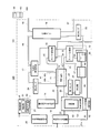
- FIG. 1 is a functional block diagram of a fuel cell system according to Embodiment 1 of the present invention.
- a fuel cell system 100 As shown in FIG. 1, a fuel cell system 100 according to Embodiment 1 of the present invention includes a casing 101 in which a fuel cell 11 and the like are arranged and a remote controller 102, and operates the remote controller 102. Thus, the fuel cell system can be started and stopped.
- the fuel cell 11 in the fuel cell system 100 is composed of a polymer electrolyte fuel cell, and the fuel cell 11 includes cells 9 having a plate-like overall shape stacked in the thickness direction. The cell stack is formed.
- the fuel cell 11 is not limited to a polymer electrolyte fuel cell, and a fuel cell such as a phosphoric acid fuel cell may be used.
- FIG. 2 is a cross-sectional view schematically showing a schematic configuration of a cell stack of the fuel cell 11 in the fuel cell system 100 shown in FIG.
- the cell 9 includes an MEA 3 (Membrane-Electrode-Assembly: electrolyte membrane-electrode assembly), a gasket 4, an anode separator 5a, and a cathode separator 5b.
- the MEA 3 includes a polymer electrolyte membrane 1 that selectively transports hydrogen ions, an anode 2a, and a cathode 2b.
- the anode 2a and the cathode 2b (these are referred to as gas diffusion electrodes) are polymers. It is provided on both surfaces of the electrolyte membrane 1 so as to be located inward from the peripheral edge.
- a pair of ring-shaped rubber gaskets 4 is disposed around the anode 2a and the cathode 2b with the polymer electrolyte membrane 1 interposed therebetween. And the electroconductive anode separator 5a and the cathode separator 5b are arrange
- a main surface (hereinafter referred to as an inner surface) that contacts the MEA 3 of the anode separator 5a is provided with a groove-like fuel gas flow path 6 through which fuel gas flows, while the main surface that contacts the MEA 3 of the cathode separator 5b
- a groove-like oxidant gas flow path 7 through which the oxidant gas flows is provided on the surface (hereinafter referred to as the inner surface).
- cooling water flow paths 8 through which the cooling water flows are provided on the outer surfaces of the anode separator 5a and the cathode separator 5b.
- a fuel gas supply manifold hole around the polymer electrolyte membrane 1, the gasket 4, and the separators 5a and 5b, there are a fuel gas supply manifold hole, a fuel gas discharge manifold hole, and an oxidant gas supply manifold, each including a through hole in the thickness direction.
- a hole, an oxidizing gas discharge manifold hole, a cooling water supply manifold hole, and a cooling water discharge manifold hole (all not shown).
- a cell stack is formed, and a current collector plate, an insulating plate, and an end plate (all not shown) are provided at both ends of the cell stack.
- the cell stack 90 is formed by arranging and fastening with a fastener (not shown).
- manifold holes such as fuel gas supply manifold holes provided in the polymer electrolyte membrane 1, the gasket 4, and the separators 5a and 5b are connected in the thickness direction so that the fuel gas supply manifold is provided. Etc., each manifold is formed.
- a fuel gas internal channel 71 is constituted by a fuel gas supply manifold, a fuel gas discharge manifold, and a fuel gas channel 6 provided in each anode separator 5a so as to connect them (FIG. 1).
- Oxidant gas supply manifold, oxidant gas discharge manifold, and oxidant gas flow path 7 provided in each cathode separator 5b so as to connect these, and oxidant gas internal flow path 72 is The cooling water supply manifold, the cooling water discharge manifold, and the cooling water flow path 8 provided in each of the separators 5a and 5b so as to connect them are configured (see FIG. 1). Not shown).
- the hydrogen generator 13 has a burner heating unit 81 and a reformer 83 as a combustor of the present invention, and the burner heating unit 81 has an igniter 82.
- a combustion gas supply port (not shown) of the burner heating unit 81 is connected to a downstream end of the fuel gas internal flow channel 71 of the fuel cell 11 through an anode off gas supply channel (anode off gas flow channel) 34 described later.
- the surplus fuel gas that has not been used in the anode 2a of the fuel cell 11 is supplied as off-gas (combustion gas).
- the raw material gas supply device 12 is connected to the burner heating unit 81 via the combustion gas supply path 31a so that the raw material gas is supplied to the burner heating unit 81 when the fuel cell system 100 is started. It is configured.
- a combustion air supply device (not shown) is connected to the burner heating unit 81 via a fuel air supply path (not shown) so that combustion air is supplied to the burner heating unit 81. It is configured.
- the burner heating unit 81 the anode off gas (or the combustion gas supply passage 31a) supplied from the anode 2a of the fuel cell 11 through the fuel gas internal passage 71 and the anode off gas supply passage 34 is supplied. And the combustion air supplied via the combustion air supply path are ignited by an igniter 82, and combustion gas is generated.
- a gas supply path 31 is connected. In the middle of the source gas supply path 31, a source gas supplier 12 is provided, and the flow rate of the source gas supplied to the hydrogen generator 13 is adjusted.
- a cathode recovery water tank 27 is connected to a reforming water supply port (not shown) of the hydrogen generator 13 via a reforming water supply path 44 described later.
- a purifier 22 for removing impurities in the recovered water
- a first pump 23 capable of adjusting the flow rate.
- an ion exchange resin is used for the purifier 22, but the present invention is not limited to this, and any impurity can be used as long as impurities in the recovered water tank can be removed as exemplified by activated carbon, zeolite, and the like. A remover may be used.
- the raw material gas supplied through the raw material gas supply path 31 and the reforming water supply path 44 are supplied using heat transfer from the combustion gas generated by the burner heating unit 81.
- a reforming reaction is performed with the water thus formed in the reformer 83, thereby generating a hydrogen-rich reformed gas.
- the generated reformed gas is subjected to a shift reaction and an oxidation reaction by a transformer and a CO remover (not shown) to generate a hydrogen-rich fuel gas in which carbon monoxide is reduced to about 10 ppm. Supplied.
- the upstream end of the fuel gas internal flow path 71 of the fuel cell 11 is connected to a fuel gas discharge port (not shown) of the hydrogen generator 13 via the fuel gas supply path 32.
- the upstream end of the oxidant gas internal flow path 72 is connected to an oxidant gas supply port (not shown) of the oxidant gas supply device 14 via the oxidant gas supply path 33.
- the oxidant gas supply unit 14 is configured by a blower (not shown) whose suction port is open to the atmosphere and a humidifier (not shown) that humidifies the sucked air with a certain amount of water vapor.
- the oxidant gas is supplied to the fuel cell 11.
- the oxidant gas supply unit 14 may be configured to use fans such as a sirocco fan.
- a cooling water circulation path 41 is connected to the fuel cell 11, and a second pump 24 capable of adjusting the flow rate is provided in the middle of the cooling water circulation path 41.
- the cooling water circulation path 41 has a cooling water forward path 41a and a cooling water return path 41b.
- the upstream end of the cooling water forward path 41 a is connected to the outlet (not shown) of the primary flow path of the cooling water heat exchanger 17, and the downstream end thereof is connected to the cooling water supply port (not shown) of the fuel cell 11.
- the upstream end of the cooling water return passage 41b is connected to a cooling water discharge port (not shown) of the fuel cell 11, and the downstream end thereof is the inlet (not shown) of the primary flow path of the cooling water heat exchanger 17. It is connected to the.
- the cooling water supplied to the fuel cell 11 collects heat generated when the reaction gas is reacted, and the inside of the fuel cell 11 can be maintained at an appropriate temperature. Further, the cooling water from which the heat generated in the fuel cell 11 is recovered is heat-exchanged with a heat medium (hot water) flowing through a secondary flow path of the cooling water heat exchanger 17 described later in the cooling water heat exchanger 17. It is cooled by doing.
- a heat medium hot water
- the upstream end of the anode offgas supply path 34 is connected to the downstream end of the fuel gas internal flow path 71 of the fuel cell 11, and the downstream end is connected to the offgas supply port of the burner heating unit 81.
- a gas-liquid separator 10 including an anode condenser 15 and an anode recovery water tank (water reservoir) 26 is provided in the middle of the anode off gas supply path 34, and the primary flow path and anode off gas of the anode condenser 15 are provided.
- the piping which comprises the supply path 34 is connected.
- An anode recovery water tank 26 is connected to the anode off gas supply path 34 on the downstream side of the anode condenser 15.
- two pipes constituting the anode off gas supply path 34 are connected to the upper part of the anode recovery water tank 26, and one pipe is connected to the upper part of the anode condenser 15 and the anode recovery water tank 26.
- the other pipe is provided so as to connect the upper part of the anode recovery water tank 26 and the burner heating unit 81.
- anode off gas a surplus fuel gas that has not been used in the anode 2a of the fuel cell 11 flows in the anode condenser 15 through the secondary flow path of the anode condenser 15 described later (hot water storage water).
- the water vapor contained in the anode off gas is condensed.
- the condensed water is stored in the anode recovery water tank 26 as recovery water.
- the anode off gas whose water vapor is reduced by condensation is supplied to the burner heating unit 81.
- a temperature detector (for example, a thermistor) 28 is provided inside the anode recovery water tank 26, and the temperature detector 28 detects the temperature of the recovered water stored in the anode recovery water tank 26.
- the control device 21 described later is configured to acquire the water temperature detected by the temperature detector 28.
- the anode recovery water tank 26 is connected to the cathode recovery water tank 27 by a connection channel 48, and the connection channel 48 is provided with a valve (not shown) for communicating or blocking the channel. It has been. Then, the control device 21 opens a valve (not shown) when a predetermined amount of the recovered water stored in the anode recovered water tank 26 is stored. Thereby, the recovered water stored in the anode recovery water tank 26 is supplied to the cathode recovery water tank 27.
- the recovery water in the cathode recovery water tank 27 is configured to be supplied to the purifier 22. That is, the recovered water in the recovered water tank 27 that is a water reservoir of the gas-liquid separator is configured to flow through the purifier 22
- an oxidant gas discharge path 35 is connected to the fuel cell 11. Specifically, the upstream end of the oxidant gas discharge path 35 is connected to the downstream end of the oxidant gas internal flow path 72 of the fuel cell 11, and the downstream end is connected to the fuel cell system 100 (housing 101). Open to the outside.
- a cathode condenser 16 is provided in the middle of the oxidant gas discharge path 35, and a secondary flow path of the cathode condenser 16 and a pipe constituting the oxidant gas discharge path 35 are connected. Further, the upstream end of the cathode recovery water flow path 43 is connected to the downstream side of the cathode condenser 16 in the oxidant gas discharge path 35, and the downstream end thereof is connected to the cathode recovery water tank 27.
- surplus oxidant gas that has not been used in the cathode 2b of the fuel cell 11 is heated in the cathode condenser 16 through the secondary flow path of the cathode condenser 16 (described later) and the heat.
- the water vapor contained in the oxidant gas is condensed.
- the condensed water is separated from the gas by an appropriate means, flows through the cathode recovery water channel 43, and is stored in the cathode recovery water tank 27 as recovered water.
- the oxidant gas whose water vapor has been reduced by condensation is discharged to the outside of the fuel cell system 100.
- a hot water storage tank 19 is disposed inside the housing 101.
- the hot water storage tank 19 is formed so as to extend in the vertical direction, and a so-called stacked boiling type hot water storage tank is used.
- An exhaust heat recovery circuit 45 is connected to the hot water storage tank 19. Specifically, the upstream end of the exhaust heat recovery circuit 45 is connected to the lower part of the hot water storage tank 19, and the downstream end thereof is connected to the upper part of the hot water storage tank 19.
- a third pump 25 capable of adjusting the flow rate is provided in the middle of the exhaust heat recovery circuit 45. Further, in the middle of the exhaust heat recovery circuit 45, an anode condenser 15, a cathode condenser 16, and a cooling water heat exchanger 17 are arranged in this order.
- a pipe constituting the recovery circuit 45 is connected.
- a hot water supply path 46 for supplying hot water stored in the hot water storage tank 19 to the user is connected to the upper part of the hot water storage tank 19.
- a water supply path 47 for supplying city water is connected to the lower part of the hot water storage tank 19, and when the amount of water stored in the hot water storage tank 19 is smaller than the predetermined amount of stored water, a predetermined amount of city water is supplied. Is configured to be supplied.
- an outside air temperature detector 20 and a control device 21 are disposed inside the housing 101.
- the outside air temperature detector 20 is composed of a thermistor, detects the outside air temperature of the fuel cell system 100, and the control device 21 is configured to acquire the outside air temperature detected by the outside air temperature detector 20. ing.
- the control device 21 has a controller 51 and an operation permitter 52.
- the control device 21 is configured by a computer such as a microcomputer, and includes a CPU, an internal memory including a semiconductor memory, a communication unit, and a clock unit (all not shown) having a calendar function.
- the controller 51 and the operation permitter 52 are realized by predetermined software stored in the internal memory.
- the operation permitter 52 acquires the temperature of the water stored in the anode recovery water tank 26 detected by the temperature detector 28, and determines whether to permit the operation of the fuel cell system 100 based on the acquired water temperature. Determine. Then, the operation permitter 52 outputs a predetermined control signal to the remote controller 102 described later, and controls the display of information related to the operation permission on the display unit 61. Further, the controller 51 outputs a control signal to the source gas supply unit 12 and / or the igniter 82 based on the determination result of the operation permission unit 52 to control them.
- the operation permitter 52 is configured to output the control signal directly to the remote controller 102 and control the display of information related to the operation permission on the display unit 61. However, the present invention is not limited to this. It is good also as a structure which outputs a control signal to the controller 51, and the controller 51 controls the display of the information regarding the driving
- the controller 51 processes these pieces of information and performs various controls relating to the fuel cell system including these controls.
- the operation permission / rejection control by the operation permitter 52 and the control of the raw material gas supplier 12 and / or the igniter 82 by the controller 51 will be described later.
- control device means not only a single controller but also a controller group in which a plurality of controllers cooperate to execute control of the fuel cell system 100.
- the controller 21 does not need to be composed of a single controller, and a plurality of controllers may be arranged in a distributed manner so that they cooperate to control the fuel cell system 100. .
- the remote controller 102 includes a control unit (not shown) configured by a microcomputer, a communication unit (not shown), a display unit 61, and a key operation unit 63.
- the control unit controls the communication unit and the like. ing.
- the remote controller 102 receives the control signal by the communication unit, and the control unit processes this and transmits it to the display unit 61.
- the display unit 61 displays that the operation of the fuel cell system 100 is not permitted (for example, during protection operation) or that the operation is permitted (for example, the display of characters during the protection operation is canceled). Therefore, the remote controller 102 corresponds to a non-permitted alarm device of the present invention.
- an operation signal input from the key operation unit 63 of the remote control 102 is transmitted to the control device 21 via the control unit and the communication unit of the remote control 102 and received by the communication unit of the control device 21 to be received from the controller 51 or This is transmitted to the operation permitter 52.
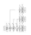
- FIG. 3 is a flowchart schematically showing the contents of the operation permission process of the fuel cell system 100 according to the first embodiment.
- the operation permission device 52 acquires the water temperature detected by the temperature detector 28 (step S1).
- the operation permitter 52 compares the first threshold value stored in the internal memory unit with the water temperature acquired in step S1 (step S2).
- the first threshold value is defined as a value that satisfies at least one of the following two conditions.
- the first condition is (I) a temperature higher than the standard environmental temperature, exists above the recovered water in the anode recovery water tank 26, and is introduced into the burner heating unit 81.
- the dew point of the anode off gas is the water temperature (for example, 45 ° C.) in the anode recovery water tank 26 that is estimated to be equal to or higher than the dew point at which the burner heating unit 81 misfires.
- the dew point of the anode off gas flowing into the burner heating unit 81 is estimated based on the water temperature in the anode recovered water tank 26. Can do. Further, since the water temperature in the anode recovery water tank 26 and the outside air temperature have a correlation, the dew point of the anode off gas flowing into the burner heating unit 81 is estimated based on the temperature detected by the outside air temperature detector 20. Also good. In this case, the first threshold value is higher than the standard environmental temperature with respect to the detected temperature detected by the outside air temperature detector 20, and the dew point of the anode off gas introduced into the burner heating unit 81.
- the outside air temperature value estimated to be equal to or higher than the dew point at which the burner heating unit 81 misfires is appropriately set.
- the first threshold value the water vapor partial pressure of the anode off-gas supplied to the burner heating unit 81 in a high-temperature environment before the fuel cell system 100 is started and during operation.
- the combustion failure abnormality non-ignition abnormality, misfire abnormality, etc.
- the first threshold is preferably (II) a temperature higher than the standard environmental temperature and not higher than the heat-resistant upper limit temperature (for example, 50 ° C.) of the purifier 22.
- the water temperature of the recovery water in the anode recovery water tank 26 is based on the temperature detected by the outside air temperature detector 20. It may be estimated.
- the first threshold value is higher than the standard environmental temperature with respect to the detected temperature detected by the outside air temperature detector 20, and the water temperature of the anode recovery water tank 26 is equal to that of the purifier 22.
- An outside air temperature value estimated to be a temperature equal to or lower than the heat resistant upper limit temperature (for example, 50 ° C.) is appropriately set.
- deterioration of the purifier 22 proceeds as the recovered water whose water temperature has increased in a high temperature environment flows before the fuel cell system 100 is started and during operation. Can be suppressed.
- the first threshold value is set so as to satisfy both the conditions (I) and (II) (for example, 45 ° C.), the first threshold value is obtained when the first threshold value satisfies only the respective conditions. It is more preferable because it is expected to realize both of the effects.
- the first threshold value that satisfies the two conditions may be a temperature value different from each other, or may be the same temperature value.
- a second threshold eg, 40 ° C.
- the water temperature that was equal to or higher than the second threshold value and lower than the first threshold value is (iii) equal to or higher than the first threshold value, and (iV) the water temperature that is equal to or higher than the first threshold value.
- the operation permission processing by the operation permission device 52 will be specifically described in case where it is less than the first threshold value and greater than or equal to the second threshold value.
- step S3 When water temperature is less than 2nd threshold value, it progresses to step S3 from step S2.
- the operation permitter 52 compares the second threshold value stored in the internal memory unit with the water temperature acquired in step S1.
- the process proceeds to step S7.
- step S7 the operation permission device 52 turns on the operation permission flag.
- the controller 51 satisfies a predetermined activation condition, for example, the user operates the key operation unit 63 of the remote controller 102 to instruct the start of operation of the fuel cell system 100, and the control unit of the remote controller 102
- the operation start request signal is input to the controller 51, the operation of the fuel cell system 100 is started. Further, when the fuel cell system 100 is in operation, the controller 51 continues the operation.
- the operation permitter 52 outputs a signal not to display a display indicating that the protection operation is being performed on the display unit 61 on the remote controller 102 (step S8). Thereby, the display unit 61 of the remote controller 102 does not display a display indicating that the protection operation is being performed.
- step S1 When the water temperature that is lower than the second threshold is equal to or higher than the second threshold and lower than the first threshold, the water temperature acquired in step S1 is equal to or higher than the second threshold and the first If it is less than the threshold, the process proceeds from step S2 to step S3.
- step S3 the operation permitter 52 compares the second threshold value stored in the storage unit with the water temperature acquired in step S1.
- the process proceeds to step S4.
- step S4 the operation permission device 52 determines whether or not the operation permission flag is ON. As described above, when the water temperature is lower than the second threshold, the operation permission flag is set to ON in step S7. For this reason, when the water temperature that is lower than the second threshold is equal to or higher than the second threshold and lower than the first threshold, the operation permission flag is ON, and the process proceeds to step S7.
- step S7 the operation permission device 52 sets the operation permission flag to ON again in the same manner as in the above (i). That is, the state where the operation permission flag is ON is maintained.
- the controller 51 of the remote controller 102 instructs the controller 51.
- the controller 51 confirms that the operation permission flag is ON, and starts the operation of the fuel cell system 100. Further, when the fuel cell system 100 is in operation, the controller 51 continues the operation.
- the operation permitter 52 outputs again a signal that does not cause the remote controller 102 to display a display indicating that the protective operation is being performed on the display unit 61 (step S8). Thereby, the display unit 61 of the remote controller 102 does not display a display indicating that the protection operation is being performed.
- step S9 When it is more than a 1st threshold value, it progresses to step S9 from step S2.
- the operation permission flag is turned OFF.
- the operation permitter 52 outputs a signal for displaying a “protecting operation” display to notify the remote controller 102 that the operation of the fuel cell system is not permitted on the display unit 61 ( Step S10).
- the display unit 61 of the remote controller 102 displays “protecting operation in progress”, and the user can understand why the fuel cell system is not started and operated.
- step S1 When the water temperature that is equal to or higher than the first threshold is lower than the first threshold and equal to or higher than the second threshold, the water temperature acquired in step S1 is lower than the first threshold and the second If it is equal to or greater than the threshold value, the process proceeds from step S2 to step S3. In step S3, since the water temperature is equal to or higher than the second threshold value, the process proceeds to step S4.
- step S4 the operation permission device 52 determines whether or not the operation permission flag is ON. As described above, when the water temperature is equal to or higher than the first threshold, the operation permitter 52 turns off the operation permission flag in step S9. For this reason, when the water temperature that is equal to or higher than the first threshold is lower than the first threshold and equal to or higher than the second threshold, the operation permission flag is OFF, and the process proceeds to step S5. The controller 51 turns off the operation permission flag in step S9 and stops the operation of the fuel cell system 100.
- step S5 the operation permission device 52 turns the operation permission flag off again. That is, the state where the operation permission flag is OFF is maintained. Thereby, the controller 51 maintains the operation stop state of the fuel cell system 100.
- the operation permitter 52 sends a signal to the remote controller 102 to display the display of “protecting operation”. Output (step S6). Thereby, the display of “protecting operation” is maintained on the display unit 61 of the remote controller 102.
- the operation permitter 52 already uses the fuel cell system itself even if the water temperature is lower than the first threshold and equal to or higher than the second threshold. If the operation of 100 is permitted (if the operation permission flag is ON), the operation of the fuel cell system 100 is permitted. On the other hand, after the temperature of the outside air becomes equal to or higher than the first threshold, the operation of the fuel cell system 100 is not permitted until it becomes equal to or lower than the second threshold. That is, the difference between the first threshold value in step S2 and the second threshold value in step S3 becomes hysteresis, and an unnecessary chattering operation in the operation control of the operation permitter 52 can be suppressed.
- the stop process is defined as an operation from when the control device 21 outputs a stop signal until the fuel cell system 100 completes the process. Further, the fuel cell system 100 stopping its operation means a standby state after the stop process is completed until the next start command is output from the control device 21. Meanwhile, the control device 21 and the outside temperature detector 20 are operating.
- the remote controller 102 When the user operates the key operation unit 63 of the remote controller 102 to instruct the start of operation of the fuel cell system 100, the remote controller 102 outputs an operation start request signal to the controller 51.
- the controller 51 issues an activation command and outputs a raw material supply signal to the burner heating unit 81 to the raw material gas supplier 12 when the operation permission flag is ON.
- a combustion air supply signal to the burner heating unit 81 is output to a combustion air supply unit (not shown).
- the raw material gas is supplied to the burner heating unit 81 from the raw material gas supply device 12 through the combustion gas supply passage 31a, and from the combustion air supply device through the fuel air supply passage (not shown).
- the combustion air is supplied to the burner heating unit 81.
- the controller 51 outputs a supply signal to the source gas supply device 12 and the combustion air supply device, and then outputs an ignition signal to the igniter 82 after a predetermined time has elapsed.
- the igniter 82 performs an ignition operation, and the raw material gas and the combustion air supplied to the burner heating unit 81 are combusted to generate combustion gas.
- the controller 51 outputs a source gas supply signal to the hydrogen generator 13 to the source gas supplier 12.
- the raw material gas is supplied from the raw material gas supply device 12 to the hydrogen generator 13, and the hydrogen generator 13 generates fuel gas.
- the generated fuel gas is used in the anode 2a of the fuel cell 11.
- Excess fuel gas that has not been used in the anode 2 a of the fuel cell 11 is supplied to the anode offgas supply path 34.
- the anode off gas supplied to the anode off gas supply path 34 flows through the anode off gas supply path 34, the water vapor contained in the anode off gas is condensed into water by the anode condenser 15 and separated.
- the anode off gas from which the water has been separated is supplied to the burner heating unit 81.
- the controller 51 When the anode off gas is supplied to the burner heating unit 81, the controller 51 outputs a source gas supply stop signal from the source gas supply unit 12 to the burner heating unit 81. Thereby, the source gas supply device 12 stops the supply of the source gas to the burner heating unit 81.
- the operation permitter 52 is: The operation of the fuel cell system 100 is stopped.
- the anode off-gas having an increased water vapor partial pressure remains in the anode off-gas supply path 34.
- the outside air temperature decreases and the temperature detected by the temperature detector 28 becomes lower than the second threshold value
- liquid water from the anode off gas is condensed on the inner surface of the anode off gas supply path 34.
- the operation permission device 52 permits the operation of the fuel cell system 100 and satisfies a predetermined activation condition
- the controller 51 issues a start command and restarts (restarts) the operation of the fuel cell system 100
- the burner heating unit 81 is supplied with condensed water as well as the anode off gas.
- the igniter 82 only performs a normal ignition operation (i.e., performs an ignition operation for a predetermined time and repeats this ignition operation a predetermined number of times)
- the raw material gas supplied to the burner heating unit 81 reacts with the combustion air, and promptly Ignition and combustion may not start.
- “normal” in this specification refers to cases other than the case where the temperature detected by the temperature detector 28 is equal to or higher than the first threshold and then lower than the second threshold.
- the controller 51 controls the source gas supplier 12 and / or the igniter 82 as follows. Ignition operation is performed.
- the controller 51 determines that the amount of the raw material gas supplied from the raw material gas supply device 12 to the burner heating unit 81 after the start command is issued and before the ignition operation by the igniter 82 is started is the normal start processing.
- the raw material gas supply device 12 is controlled so as to be more than that. Specifically, the raw material gas supplier 12 is controlled so that the flow rate of the raw material gas supplied to the burner heating unit 81 before the ignition operation is started is larger than that in the normal startup process.
- the combustion air supply device is controlled so that the combustion air is supplied from the combustion air supply device via the fuel air supply path. Thereby, more raw material gas than usual is supplied to the burner heating part 81, and the gas containing the dew condensation water supplied to the burner heating part 81 at the time of restarting is scavenged with raw material gas and combustion air.
- the controller 51 controls the igniter 82 to perform an ignition operation after a predetermined time has elapsed, as in a normal case.
- the burner heating unit 81 is ignited by the ignition operation of the igniter 82 because the gas containing the dew condensation water supplied to the burner heating unit 81 is scavenged with the raw material gas and the combustion air.
- the source gas and the combustion air can be combusted.
- controller 51 may scavenge the gas containing the dew condensation water supplied to the burner heating part 81 more fully with source gas and combustion air, the flow volume of source gas will become larger than a normal starting process.
- the igniter 82 is ignited after elapse of a time longer than the gas flow time (the predetermined time) to the burner heating unit 81 before the ignition operation in the normal startup process. You may control to perform operation
- the ignition operation by the igniter 82 of the burner heating unit 81 is performed. Ignition is improved.
- the controller 51 controls the source gas supply unit 12 so that the flow rate of the source gas supplied from the source gas supply unit 12 to the burner heating unit 81 is the same as that in the normal startup process.
- the ignition operation is performed after a long time has elapsed since the supply of the raw material gas from the raw material gas supply device 12 is started compared to the case of the normal start-up process (the ignition operation is delayed from the case of the normal start-up process). ) May be controlled as follows.
- the controller 51 controls the raw material gas supply device 12 so that the flow rate of the raw material gas supplied from the raw material gas supply device 12 to the burner heating unit 81 is the same as the normal flow rate.
- the ignition operation is started after the lapse of the same predetermined time as in the normal start-up process, but the upper limit value of the number of retries of the ignition operation is higher than the normal case. It may be controlled to increase the number of times, and the operation time per ignition operation may be controlled to be longer than the normal startup process.
- the ignitability during the ignition operation by the igniter 82 of the burner heating unit 81 can be improved.
- the temperature detector 28 when the temperature (water temperature; outside air temperature) detected by the temperature detector 28 is equal to or higher than the first threshold value, the anode off gas above the recovered water in the anode recovered water tank 26 The water vapor partial pressure rises, and there is a possibility that the combustion failure of the burner heating unit 81 (ignition failure, misfire after starting combustion, etc.) may occur.
- the temperature of the water condensed in the anode condenser 15 and recovered in the anode recovery water tank 26 rises, and the temperature of the recovered water flowing through the purifier 22 becomes the purifier 22 ( For example, when the durability temperature of the ion exchange resin) is exceeded, deterioration of the purifier 22 may be promoted.
- the operation permitter 52 when the operation permitter 52 is equal to or higher than the first threshold that is higher than the standard environment temperature, the temperature detected by the temperature detector 28, the fuel cell system. It is controlled not to allow 100 operations.
- production of the subject of at least any one of the said 1st subject and the 2nd subject can be suppressed. That is, the first effect of suppressing the occurrence of combustion failure abnormality (non-ignition abnormality or misfiring abnormality) of the burner heating unit 81 of the fuel cell system 100 and the second effect of suppressing deterioration of the purifier 22. It is possible to realize at least one of the effects.
- the fuel cell system 100 when the temperature detected by the temperature detector 28 becomes equal to or higher than the first threshold value and then becomes lower than the second threshold value and the fuel cell system 100 is restarted,
- the raw material gas is supplied so that the amount of the raw material gas supplied from the raw material gas supply device 12 to the burner heating unit 81 before the ignition operation by the igniter 82 is started is larger than that in the normal startup process.
- the gas supply device 12 By controlling the gas supply device 12, the ignitability of the burner heating unit 81 at the time of restart can be improved, and unnecessary operation errors (abnormal ignition failure) of the fuel cell system 100 can be suppressed.
- the reliability of 100 can be improved.
- FIG. 4 is a functional block diagram of a fuel cell system of Modification 1 in fuel cell system 100 according to Embodiment 1 of the present invention.
- the fuel cell system 100 according to the first modification has the same basic configuration as the fuel cell system 100 according to the first embodiment, but is not provided with an anode condenser.
- the liquid separator 10 is substantially composed of an anode recovery water tank 26.
- the anode off-gas supply channel 34 connects the fuel gas internal channel 71 and the burner heating unit 81 via the anode recovery water tank 26.
- the water vapor contained in the anode off gas is condensed while flowing through the anode off gas supply path 34.
- the condensed water is stored in the recovered water tank 26 so that the condensed water and gas can be separated. That is, the recovered water tank 26 functions as a gas-liquid separator.
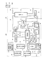
- FIG. 5 is a functional block diagram of the fuel cell system according to Embodiment 2 of the present invention
- FIG. 6 is a flowchart schematically showing the contents of the operation permission process of the fuel cell system shown in FIG.
- the fuel cell system 100 according to the second embodiment of the present invention has the same basic configuration as the fuel cell system 100 according to the first embodiment.
- the difference is that the tank 26 and the cathode recovery water tank 27 are replaced with one recovery water tank 18.
- an anode recovered water flow path 42 that connects the anode off gas supply path 34 and the recovered water tank 18 is provided downstream of the anode condenser 15 in the anode off gas supply path 34. Yes.
- a cathode recovery water flow path 43 that connects the oxidant gas discharge path 35 and the recovered water tank 18 (here, the anode recovery water flow path 42) is provided on the downstream side of the cathode condenser 16 in the oxidant gas discharge path 35. It has been.
- the water condensed in the anode condenser 15 is separated from the gas at the branch point between the anode off-gas supply path 34 and the anode recovery water flow path 42, and flows through the anode recovery water flow path 42 as recovered water. It is stored in the recovered water tank 18.
- the water condensed in the cathode condenser 16 is separated from the gas at the branch point between the oxidant gas discharge path 35 and the cathode recovery water flow path 43 opened to the atmosphere, and passes through the cathode recovery water flow path 43.
- the collected water is stored in the recovered water tank 18 as recovered water.
- the temperature detector 28 is not provided, and the outside air temperature detected by the outside air temperature detector 20 is stored in the water reservoir (here Then, the water temperature stored in the recovered water tank 18) is detected as a substitute temperature, and the control device 21 is configured to acquire the outside air temperature detected by the outside air temperature detector 20. Then, the operation permitter 52 acquires the outside air temperature detected by the outside air temperature detector 20, and the same as in the first embodiment based on whether or not the acquired outside air temperature is equal to or higher than the first threshold value. It is determined whether or not the operation of the fuel cell system 100 is permitted.
- the first threshold value set for the detected temperature of the outside air temperature detector 20 is appropriately set so as to satisfy at least one of the first condition and the second condition as in the first embodiment.
- the fuel cell system according to the third embodiment of the present invention has the same basic configuration as the fuel cell system 100 according to the second embodiment, but the operation control by the operation permitter 52 and the remote controller 102 as an abnormality alarm device. Will also be described below.
- FIG. 7 is a flowchart schematically showing the contents of the operation permission process of the fuel cell system according to the third embodiment.
- the processing when the outside air temperature becomes equal to or higher than the first threshold is different from that in the fuel cell system 100 according to the second embodiment.
- step S11 the operation permitter 52 acquires the current time from the clock unit. Then, the operation permitter 52 determines whether or not the time information acquired in Step S11 corresponds to the summer season (for example, July to September) stored in the storage unit (Step S12).
- the operation permission flag is turned off (step S15).
- the predetermined activation condition for example, the user operates the key operation unit 63 of the remote controller 102 to instruct the start of operation of the fuel cell system 100, and the control unit of the remote controller 102 Even when the operation start request signal is input to the controller 51, the operation start operation of the fuel cell system 100 is not performed. Further, when the fuel cell system 100 is in operation, the controller 51 stops the operation.
- the operation permitter 52 outputs a signal for displaying a “protecting operation” display to notify the remote controller 102 that the operation of the fuel cell system is not permitted on the display unit 61 ( Step S16).
- the display unit 61 of the remote controller 102 displays “protecting operation in progress”, and the user can understand the reason why the fuel cell system 100 is not started and operated.
- the operation permitter 52 turns off the operation permission flag (step S13).
- the predetermined activation condition for example, the user operates the key operation unit 63 of the remote controller 102 to instruct the start of operation of the fuel cell system 100, and the control unit of the remote controller 102 Even when the operation start request signal is input to the controller 51, the operation start operation of the fuel cell system 100 is not performed. Further, when the fuel cell system 100 is in operation, the controller 51 stops the operation.
- the operation permitter 52 outputs a signal on the display unit 61 of the remote controller 102 to display a display indicating that a predetermined device in the fuel cell system is likely to be faulty and needs maintenance (step S14). ).
- the display unit 61 displays that the fuel cell system 100 has an abnormality requiring maintenance.
- the control unit of the remote controller 102 sends a signal notifying the maintenance company that the fuel cell system 100 is in abnormality. Output. That is, the remote controller 102 functions as an abnormality alarm.
- the remote controller 102 is configured to function as an abnormality alarm, but is not limited thereto, and the communication unit of the control device 21 functions as an abnormality alarm, that is, the communication unit of the control device 21 You may comprise so that the signal which alert
- the temperature of the recovered water stored in the anode recovered water tank 26 is detected by the temperature detector 28 as the temperature of the anode recovered water tank 26.
- the present invention is not limited to this.
- the temperature of the anode recovery water tank 26 the temperature of the recovery water stored in the cathode recovery water tank 27 may be detected, and the temperature of the anode recovery water tank 26 is determined from the temperature of the cooling water circulating in the cooling water circulation path 41.
- the heat medium circulating in the exhaust heat recovery circuit 45 is water
- the temperature of the anode recovery water tank 26 may be estimated from this temperature. That is, as long as the water temperature in the water path existing in the fuel cell system can be detected, it may be provided at any location.
- the temperature detector 28 is composed of a thermistor.
- the present invention is not limited to this, and it may be composed of a thermocouple.
- the outside temperature detector 20 was comprised with the thermistor, it is not limited to this, You may comprise with the thermocouple.
- the outside air temperature detector 20 may be installed at any location in the fuel cell system 100 (inside the casing 101) as long as it can detect a temperature correlated with the outside air temperature. You may comprise so that it may provide outside (the outer side including the outer wall surface of the housing
- the outside air temperature detector 20 may be configured as an outside air temperature obtaining device that obtains the outside air temperature from the outside using a communication signal without providing a thermocouple, a thermistor, or the like.
- the operation permitter 52 turns on / off the operation permission flag to permit / deny operation of the fuel cell system 100, and the controller 51 confirms ON / OFF of the operation permission flag
- the controller 51 issues an activation command regardless of whether the operation permission flag is ON or OFF.
- the permitter 52 is not permitted to drive, the start command issued from the controller 51 is blocked, thereby prohibiting the operation, and when permitted, the start command is not blocked.
- the configuration may be such that driving permission is executed.
- the controller 51 outputs an operation continuation signal regardless of whether the operation permission flag is ON or OFF.
- control is performed.
- the operation disapproval that is, the operation of the fuel cell system 100 is stopped
- the operation continuation signal is not blocked.
- a configuration may be adopted in which operation permission (that is, operation continuation of the fuel cell system 100) is executed.
- the fuel cell system of the present invention can be used to heat a reformer burner when the fuel cell system is started up in a high temperature environment or when the outside air temperature rises to a high temperature environment during operation of the fuel cell system. This is useful in the technical field of fuel cells because it can suppress non-ignition abnormalities and misfiring abnormalities due to an increase in the water vapor content of the anode off-gas in the section.
- the fuel cell system of the present invention can be used when the fuel cell system is started in a high temperature environment, or when the outside air temperature rises during operation of the fuel cell system and becomes a high temperature environment. Since water that exceeds the endurance temperature can be suppressed from being supplied to the purifier, it is useful in the technical field of fuel cells.
Abstract
Description
前記第1の閾値は、前記貯水器内の前記水よりも上方に存在する前記アノードオフガスの露点が前記燃焼器が失火する露点以上になると推定される前記貯水器内の水温であってもよい。
2a アノード
2b カソード
3 MEA(Membrane-Electrode-Assembly:電解質膜-電極接合体)
4 ガスケット
5a アノードセパレータ
5b カソードセパレータ
6 燃料ガス流路
7 酸化剤ガス流路
8 冷却水流路
9 セル
10 気液分離器
11 燃料電池
12 原料ガス供給器
13 水素生成装置
14 酸化剤ガス供給器
15 アノード凝縮器
16 カソード凝縮器
17 冷却水熱交換器
18 回収水タンク
19 貯湯タンク
20 外気温度検知器
21 制御装置
22 浄化器
23 第1ポンプ
24 第2ポンプ
25 第3ポンプ
26 アノード回収水タンク(貯水器)
27 カソード回収水タンク
28 温度検知器
31 原料ガス供給路
31a 燃焼用ガス供給路
32 燃料ガス供給路
33 酸化剤ガス供給路
34 アノードオフガス供給路(アノードオフガス流路)
35 酸化剤ガス排出路
41 冷却水循環路
41a 冷却水往路
41b 冷却水復路
42 アノード回収水流路
43 カソード回収水流路
44 改質用水供給路
45 排熱回収循環路
46 貯湯水供給路
48 接続流路
51 制御器
52 運転許可器
61 表示部
62 異常報知器
63 キー操作部
71 燃料ガス内部流路
72 酸化剤ガス内部流路
81 バーナ加熱部
82 点火器
83 改質器
90 セルスタック
100 燃料電池システム
101 筐体
102 リモコン
200 燃料電池発電システム
201 燃料電池
202 燃焼部
203 改質器
204 アノードオフガス熱交換器
205 カソードオフガス熱交換器
206 冷却水熱交換器
207 貯湯槽
208 循環経路
209 水タンク
210 アノードオフガス経路
300 燃料電池システム
301 燃料電池
302 水分除去器
303 燃料処理器
304 バーナ
305 不純物除去手段
(実施の形態1)
[燃料電池システムの構成]
図1は、本発明の実施の形態1に係る燃料電池システムの機能ブロック図である。
本実施の形態1に係る燃料電池システム100の動作について説明する。なお、燃料電池システム100の一般的動作は、周知であるため、その詳細な説明は省略する。
ステップS1で取得した水温が、第2の閾値未満である場合には、ステップS2からステップS3に進む。ステップS3では、運転許可器52は、内部メモリ部に記憶されている第2の閾値とステップS1で取得した水温を比較する。ここでは、水温が第2の閾値未満であるので、ステップS7に進む。
ステップS1で取得した水温が、第2の閾値以上、かつ、第1の閾値未満である場合には、ステップS2からステップS3に進む。ステップS3では、運転許可器52は、記憶部に記憶されている第2の閾値とステップS1で取得した水温を比較する。ここでは、外気温度が第2の閾値以上であるので、ステップS4に進む。
ステップS1で取得した水温が、第1の閾値以上である場合には、ステップS2からステップS9に進む。ステップS9では、運転許可フラグをOFFにする。これにより、制御器51は、所定の起動条件を満足した場合、例えば、利用者がリモコン102のキー操作部63を操作して、燃料電池システム100の運転開始を指示し、リモコン102の制御部から制御器51に運転開始要求信号が入力された場合であっても、燃料電池システム100の運転開始動作を行わない。また、燃料電池システム100が運転中である場合には、制御器51は、その運転を停止させる。
ステップS1で取得した水温が、第1の閾値未満、かつ、第2の閾値以上である場合には、ステップS2からステップS3に進む。ステップS3では、水温が、第2の閾値以上であるので、ステップS4に進む。
次に、本実施の形態1に係る燃料電池システム100の作用効果について説明する。
図4は、本発明の実施の形態1に係る燃料電池システム100における変形例1の燃料電池システムの機能ブロック図である。
図5は、本発明の実施の形態2に係る燃料電池システムの機能ブロック図であり、図6は、図5に示す燃料電池システムの運転許可処理の内容を概略的に示すフローチャートである。
本発明の実施の形態3に係る燃料電池システムは、実施の形態2に係る燃料電池システム100と基本的構成は同じであるが、運転許可器52による運転制御と、リモコン102が異常報知器としても機能する点が異なり、以下に説明する。
Claims (14)
- 燃料ガス及び酸化剤ガスを用いて発電する燃料電池と、
前記燃料電池のアノードから排出されるアノードオフガスが通流するアノードオフガス流路と、
前記アノードオフガス流路に設けられ、前記アノードオフガスからその水分を分離させ、分離させた水分を水として貯える貯水器を有する気液分離器と、
前記貯水器の水温を検知する温度検知器と、
前記温度検知器の検知温度が標準環境温度よりも高い第1の閾値以上である場合には、燃料電池システムの運転を許可しないように構成されている運転許可器と、を備える、燃料電池システム。 - 原料から改質反応により前記燃料ガスを生成する改質器と、前記アノードオフガス流路から供給される前記アノードオフガスを燃焼し、前記改質器を加熱するように構成された燃焼器と、を有する水素生成器を備え、
前記第1の閾値は、前記貯水器内の前記水よりも上方に存在する前記アノードオフガスの露点が前記燃焼器が失火する露点以上になると推定される水温である、請求項1に記載の燃料電池システム。 - 前記貯水器内の前記水を利用する水利用器と、
前記貯水器より前記水利用器に供給される前記水を浄化するように構成された浄化器と、を備え、
前記第1の閾値は、前記浄化器の耐熱上限温度以下の温度である、請求項1に記載の燃料電池システム。 - 前記貯水器を含む水流路を備え、
前記温度検知器は、前記水流路内の水温を検知する水温検知器を含む、請求項1に記載の燃料電池システム。 - 前記温度検知器は、外気温度を検知する外気温検知器を含む、請求項1~3に記載の燃料電池システム。
- 前記運転許可器は、前記温度検知器の検知温度が前記第1の閾値よりも低い第2の閾値未満の場合には、前記燃料電池システムの運転を許可するように構成されている、請求項1に記載の燃料電池システム。
- 前記運転許可器は、前記燃料電池システムの起動前の前記温度検知器の検知温度が前記第1の閾値未満、かつ、前記第2の閾値以上のとき、既に前記運転許可器により運転が許可されている状態である場合には、前記燃料電池システムの運転を許可するように構成されている、請求項6に記載の燃料電池システム。
- 前記運転許可器は、前記温度検知器の検知温度が前記第1の閾値以上になった後には、前記温度検知器の検知温度が前記第2の閾値未満になるまで前記燃料電池システムの運転を許可しないように構成されている、請求項1又は7に記載の燃料電池システム。
- 前記原料を前記改質器又は前記燃焼器に供給するための原料ガス供給器と、
前記燃焼器に設けられた点火器と、
制御器と、を備え、
前記燃焼器は、起動処理において前記原料ガス供給器から供給された前記原料ガスを燃焼するように構成されており、
前記運転許可器が、前記温度検知器の検知温度が前記第1の閾値以上になってから後に前記第2の閾値未満になり、前記燃料電池システムの運転を許可してからの前記燃料電池システムの起動において、
前記制御器は、前記点火器の点火動作までに前記燃焼器に通常よりも多くの原料ガスを供給するように前記原料ガス供給器及び前記点火器の少なくともいずれか一方を制御する、請求項2に記載の燃料電池システム。 - 前記制御器は、前記燃焼器に供給される原料ガスの流量を通常より多くなるように前記原料ガス供給器を制御する、請求項9に記載の燃料電池システム。
- 前記制御器は、その点火動作を通常よりも遅らせるように前記点火器を制御する、請求項9又は10に記載の燃料電池システム。
- 前記原料を前記改質器又は前記燃焼器に供給するための原料ガス供給器と、
前記燃焼器に設けられた点火器と、
制御器と、を備え、
前記燃焼器は、起動処理において前記原料ガス供給器から供給された前記原料ガスを燃焼するように構成されており、
前記運転許可器が、前記温度検知器の検知温度が前記第1の閾値以上になってから後に前記第2の閾値未満になり、前記燃料電池システムの運転を許可してからの前記燃料電池システムの起動において、
前記制御器は、前記点火器の点火動作時間を通常よりも長くなるように前記点火器を制御する、請求項2に記載の燃料電池システム。 - 夏期以外の季節に前記温度検知器の検知温度が前記第1の閾値以上となると前記燃料電池システムの故障の旨を報知する故障報知器を備える、請求項1に記載の燃料電池システム。
- 前記運転許可器が、前記燃料電池システムの運転を許可しない場合、その旨を報知する不許可報知器を備える、請求項1に記載の燃料電池システム。
Priority Applications (4)
| Application Number | Priority Date | Filing Date | Title |
|---|---|---|---|
| EP09703463.1A EP2237354B1 (en) | 2008-01-23 | 2009-01-22 | Fuel cell system |
| US12/811,929 US8415064B2 (en) | 2008-01-23 | 2009-01-22 | Fuel cell system |
| JP2009550474A JP5410994B2 (ja) | 2008-01-23 | 2009-01-22 | 燃料電池システム |
| CN200980103009.2A CN101926038B (zh) | 2008-01-23 | 2009-01-22 | 燃料电池系统 |
Applications Claiming Priority (2)
| Application Number | Priority Date | Filing Date | Title |
|---|---|---|---|
| JP2008012275 | 2008-01-23 | ||
| JP2008-012275 | 2008-01-23 |
Publications (1)
| Publication Number | Publication Date |
|---|---|
| WO2009093456A1 true WO2009093456A1 (ja) | 2009-07-30 |
Family
ID=40900966
Family Applications (1)
| Application Number | Title | Priority Date | Filing Date |
|---|---|---|---|
| PCT/JP2009/000229 WO2009093456A1 (ja) | 2008-01-23 | 2009-01-22 | 燃料電池システム |
Country Status (5)
| Country | Link |
|---|---|
| US (1) | US8415064B2 (ja) |
| EP (1) | EP2237354B1 (ja) |
| JP (2) | JP5410994B2 (ja) |
| CN (1) | CN101926038B (ja) |
| WO (1) | WO2009093456A1 (ja) |
Cited By (4)
| Publication number | Priority date | Publication date | Assignee | Title |
|---|---|---|---|---|
| WO2012117725A1 (ja) * | 2011-03-03 | 2012-09-07 | パナソニック株式会社 | 気液分離器及び燃料電池システム |
| JP2014197458A (ja) * | 2013-03-29 | 2014-10-16 | パナソニック株式会社 | 燃料電池システム |
| JP2019160639A (ja) * | 2018-03-14 | 2019-09-19 | 大阪瓦斯株式会社 | 燃料電池システム |
| JP2021072206A (ja) * | 2019-10-30 | 2021-05-06 | 京セラ株式会社 | 燃料電池システム |
Families Citing this family (14)
| Publication number | Priority date | Publication date | Assignee | Title |
|---|---|---|---|---|
| US20130149623A1 (en) * | 2011-03-31 | 2013-06-13 | Panasonic Corporation | Fuel cell system and method of operating the same |
| WO2012153484A1 (ja) * | 2011-05-06 | 2012-11-15 | パナソニック株式会社 | 燃料電池システム及びその運転方法 |
| CN102385337A (zh) * | 2011-11-23 | 2012-03-21 | 南京禾浩通信科技有限公司 | 燃料电池安全监控系统 |
| DE102012020130B4 (de) * | 2012-10-15 | 2018-12-06 | Mann + Hummel Gmbh | Befeuchtungseinrichtung, insbesondere für eine Brennstoffzelle |
| DE102012020131A1 (de) * | 2012-10-15 | 2014-04-17 | Mann + Hummel Gmbh | Verfahren zum Betrieb einer Befeuchtungseinrichtung für eine Brennstoffzelle |
| US10256485B2 (en) | 2013-03-11 | 2019-04-09 | Ford Global Technologies, Llc | Fuel cell purge line system |
| US20140255814A1 (en) | 2013-03-11 | 2014-09-11 | Ford Global Technologies, Llc | Fuel Cell Purge Line System |
| GB201317175D0 (en) | 2013-09-27 | 2013-11-06 | Rolls Royce Plc | An apparatus and a method of controlling the supply of fuel to a combustion chamber |
| JP5735618B1 (ja) * | 2013-12-26 | 2015-06-17 | 大阪瓦斯株式会社 | 貯湯式熱源装置 |
| CN106784940B (zh) * | 2016-12-27 | 2019-04-26 | 宁波索福人能源技术有限公司 | 一种固体氧化物燃料电池发电系统 |
| AT520553B1 (de) * | 2017-12-14 | 2019-05-15 | Avl List Gmbh | Abgasnachbehandlungssystem, Reaktorsystem und Verfahren zur Abgasnachbehandlung für ein Brennstoffzellensystem |
| WO2019172337A1 (ja) * | 2018-03-07 | 2019-09-12 | 大阪瓦斯株式会社 | 燃料電池システム及び燃料電池システムの運転方法 |
| FR3091417A1 (fr) * | 2018-12-26 | 2020-07-03 | Naval Group | Système de piles à combustible pour un navire |
| DE102021211551A1 (de) * | 2021-10-13 | 2023-04-13 | Robert Bosch Gesellschaft mit beschränkter Haftung | Medienzusammenführungsvorrichtung |
Citations (9)
| Publication number | Priority date | Publication date | Assignee | Title |
|---|---|---|---|---|
| JPH0719462A (ja) * | 1993-06-29 | 1995-01-20 | Miura Co Ltd | ボイラ起動時の燃焼制御方法 |
| JPH11281055A (ja) * | 1998-03-26 | 1999-10-15 | Miura Co Ltd | バーナの起動制御方法 |
| JP2004171823A (ja) * | 2002-11-18 | 2004-06-17 | Honda Motor Co Ltd | 燃料電池スタックおよびその暖機方法 |
| JP2006147264A (ja) | 2004-11-18 | 2006-06-08 | Matsushita Electric Ind Co Ltd | 燃料電池システムおよびその運転方法 |
| JP2006228630A (ja) * | 2005-02-18 | 2006-08-31 | Nissan Motor Co Ltd | 燃料電池システムの冷却制御装置 |
| JP2006302792A (ja) * | 2005-04-25 | 2006-11-02 | Aisin Seiki Co Ltd | 燃料電池システム |
| JP2007059265A (ja) * | 2005-08-25 | 2007-03-08 | Toyota Motor Corp | 燃料電池システム |
| JP3943405B2 (ja) | 2001-12-26 | 2007-07-11 | トヨタ自動車株式会社 | 燃料電池発電システム |
| JP2007194085A (ja) * | 2006-01-19 | 2007-08-02 | Matsushita Electric Ind Co Ltd | 燃料電池発電システム、その運転方法、プログラム、及び記録媒体 |
Family Cites Families (14)
| Publication number | Priority date | Publication date | Assignee | Title |
|---|---|---|---|---|
| JP3992428B2 (ja) * | 2000-08-16 | 2007-10-17 | 三洋電機株式会社 | 燃料電池システムとその運転方法 |
| JP4037686B2 (ja) | 2001-05-23 | 2008-01-23 | 松下電器産業株式会社 | 燃料電池発電装置 |
| EP2178149B1 (en) | 2001-05-23 | 2012-07-04 | Panasonic Corporation | Fuel cell power generating system |
| JP3826770B2 (ja) * | 2001-11-16 | 2006-09-27 | 日産自動車株式会社 | 燃料改質システム |
| JP2003223912A (ja) * | 2002-01-30 | 2003-08-08 | Mitsubishi Heavy Ind Ltd | 燃料電池システム、コジェネレーションシステム及び燃料電池システム運転方法 |
| US20050112454A1 (en) * | 2003-11-25 | 2005-05-26 | Victor Gurin | Alkaline electrolyte fuel cells with improved hydrogen-oxygen supply system |
| JP4993240B2 (ja) * | 2004-03-17 | 2012-08-08 | トヨタ自動車株式会社 | 制御装置 |
| JP2006040553A (ja) | 2004-07-22 | 2006-02-09 | Matsushita Electric Ind Co Ltd | 燃料電池システム |
| JP4823502B2 (ja) * | 2004-10-14 | 2011-11-24 | 本田技研工業株式会社 | 燃料電池の停止方法及び燃料電池システム |
| JP2006147414A (ja) * | 2004-11-22 | 2006-06-08 | Honda Motor Co Ltd | 燃料電池システム |
| US20070178347A1 (en) * | 2006-01-27 | 2007-08-02 | Siepierski James S | Coolant bypass for fuel cell stack |
| JP2007317475A (ja) * | 2006-05-25 | 2007-12-06 | Toyota Motor Corp | 燃料電池システム |
| JP4988260B2 (ja) | 2006-07-06 | 2012-08-01 | パナソニック株式会社 | 燃料電池システム |
| JP5082311B2 (ja) * | 2006-07-11 | 2012-11-28 | トヨタ自動車株式会社 | 燃料電池システム |
-
2009
- 2009-01-22 EP EP09703463.1A patent/EP2237354B1/en active Active
- 2009-01-22 WO PCT/JP2009/000229 patent/WO2009093456A1/ja active Application Filing
- 2009-01-22 US US12/811,929 patent/US8415064B2/en active Active
- 2009-01-22 JP JP2009550474A patent/JP5410994B2/ja active Active
- 2009-01-22 CN CN200980103009.2A patent/CN101926038B/zh active Active
-
2013
- 2013-05-22 JP JP2013107999A patent/JP5789783B2/ja active Active
Patent Citations (9)
| Publication number | Priority date | Publication date | Assignee | Title |
|---|---|---|---|---|
| JPH0719462A (ja) * | 1993-06-29 | 1995-01-20 | Miura Co Ltd | ボイラ起動時の燃焼制御方法 |
| JPH11281055A (ja) * | 1998-03-26 | 1999-10-15 | Miura Co Ltd | バーナの起動制御方法 |
| JP3943405B2 (ja) | 2001-12-26 | 2007-07-11 | トヨタ自動車株式会社 | 燃料電池発電システム |
| JP2004171823A (ja) * | 2002-11-18 | 2004-06-17 | Honda Motor Co Ltd | 燃料電池スタックおよびその暖機方法 |
| JP2006147264A (ja) | 2004-11-18 | 2006-06-08 | Matsushita Electric Ind Co Ltd | 燃料電池システムおよびその運転方法 |
| JP2006228630A (ja) * | 2005-02-18 | 2006-08-31 | Nissan Motor Co Ltd | 燃料電池システムの冷却制御装置 |
| JP2006302792A (ja) * | 2005-04-25 | 2006-11-02 | Aisin Seiki Co Ltd | 燃料電池システム |
| JP2007059265A (ja) * | 2005-08-25 | 2007-03-08 | Toyota Motor Corp | 燃料電池システム |
| JP2007194085A (ja) * | 2006-01-19 | 2007-08-02 | Matsushita Electric Ind Co Ltd | 燃料電池発電システム、その運転方法、プログラム、及び記録媒体 |
Cited By (7)
| Publication number | Priority date | Publication date | Assignee | Title |
|---|---|---|---|---|
| WO2012117725A1 (ja) * | 2011-03-03 | 2012-09-07 | パナソニック株式会社 | 気液分離器及び燃料電池システム |
| JP5604584B2 (ja) * | 2011-03-03 | 2014-10-08 | パナソニック株式会社 | 気液分離器 |
| JP2014197458A (ja) * | 2013-03-29 | 2014-10-16 | パナソニック株式会社 | 燃料電池システム |
| JP2019160639A (ja) * | 2018-03-14 | 2019-09-19 | 大阪瓦斯株式会社 | 燃料電池システム |
| JP7002375B2 (ja) | 2018-03-14 | 2022-01-20 | 大阪瓦斯株式会社 | 燃料電池システム |
| JP2021072206A (ja) * | 2019-10-30 | 2021-05-06 | 京セラ株式会社 | 燃料電池システム |
| JP7424794B2 (ja) | 2019-10-30 | 2024-01-30 | 京セラ株式会社 | 燃料電池システム |
Also Published As
| Publication number | Publication date |
|---|---|
| US20100279188A1 (en) | 2010-11-04 |
| CN101926038A (zh) | 2010-12-22 |
| US8415064B2 (en) | 2013-04-09 |
| EP2237354A4 (en) | 2014-06-18 |
| JP5410994B2 (ja) | 2014-02-05 |
| JPWO2009093456A1 (ja) | 2011-05-26 |
| EP2237354A1 (en) | 2010-10-06 |
| JP5789783B2 (ja) | 2015-10-07 |
| EP2237354B1 (en) | 2019-12-11 |
| JP2013219041A (ja) | 2013-10-24 |
| CN101926038B (zh) | 2015-09-30 |
Similar Documents
| Publication | Publication Date | Title |
|---|---|---|
| JP5789783B2 (ja) | 燃料電池システム | |
| JP5106702B1 (ja) | 燃料電池システム | |
| US8747498B2 (en) | Hydrogen generator and fuel cell system comprising the same | |
| EP2963725A1 (en) | Fuel cell system | |
| JP5988701B2 (ja) | 燃料電池システム | |
| JP5112107B2 (ja) | 燃料電池発電システム | |
| JP5148681B2 (ja) | 燃料電池システム | |
| JP7127427B2 (ja) | 燃料電池システム | |
| JP2006093023A (ja) | 燃料電池システム及びこれを用いた電力供給システム | |
| JP2014089890A (ja) | 燃料電池式発電装置及びコージェネレーションシステム | |
| JP2017157295A (ja) | 燃料電池システム | |
| JP6424494B2 (ja) | 燃料電池システム | |
| JP5613374B2 (ja) | 燃料電池システム | |
| JP6984170B2 (ja) | 燃料電池システム | |
| JP7472805B2 (ja) | 燃料電池システム | |
| JP6330522B2 (ja) | 燃料電池システム | |
| JP2023104027A (ja) | 燃料電池システム | |
| JP2008305690A (ja) | 燃料電池用の改質装置 |
Legal Events
| Date | Code | Title | Description |
|---|---|---|---|
| WWE | Wipo information: entry into national phase |
Ref document number: 200980103009.2 Country of ref document: CN |
|
| 121 | Ep: the epo has been informed by wipo that ep was designated in this application |
Ref document number: 09703463 Country of ref document: EP Kind code of ref document: A1 |
|
| ENP | Entry into the national phase |
Ref document number: 2009550474 Country of ref document: JP Kind code of ref document: A |
|
| WWE | Wipo information: entry into national phase |
Ref document number: 12811929 Country of ref document: US |
|
| WWE | Wipo information: entry into national phase |
Ref document number: 2009703463 Country of ref document: EP |
|
| NENP | Non-entry into the national phase |
Ref country code: DE |