WO2009084648A1 - Composite de produit d'acier et de résine et procédé de fabrication du composite - Google Patents
Composite de produit d'acier et de résine et procédé de fabrication du composite Download PDFInfo
- Publication number
- WO2009084648A1 WO2009084648A1 PCT/JP2008/073769 JP2008073769W WO2009084648A1 WO 2009084648 A1 WO2009084648 A1 WO 2009084648A1 JP 2008073769 W JP2008073769 W JP 2008073769W WO 2009084648 A1 WO2009084648 A1 WO 2009084648A1
- Authority
- WO
- WIPO (PCT)
- Prior art keywords
- resin
- steel
- composite
- adhesive
- aluminum
- Prior art date
Links
Images


Classifications
-
- B—PERFORMING OPERATIONS; TRANSPORTING
- B29—WORKING OF PLASTICS; WORKING OF SUBSTANCES IN A PLASTIC STATE IN GENERAL
- B29C—SHAPING OR JOINING OF PLASTICS; SHAPING OF MATERIAL IN A PLASTIC STATE, NOT OTHERWISE PROVIDED FOR; AFTER-TREATMENT OF THE SHAPED PRODUCTS, e.g. REPAIRING
- B29C45/00—Injection moulding, i.e. forcing the required volume of moulding material through a nozzle into a closed mould; Apparatus therefor
- B29C45/14—Injection moulding, i.e. forcing the required volume of moulding material through a nozzle into a closed mould; Apparatus therefor incorporating preformed parts or layers, e.g. injection moulding around inserts or for coating articles
- B29C45/14311—Injection moulding, i.e. forcing the required volume of moulding material through a nozzle into a closed mould; Apparatus therefor incorporating preformed parts or layers, e.g. injection moulding around inserts or for coating articles using means for bonding the coating to the articles
-
- B—PERFORMING OPERATIONS; TRANSPORTING
- B29—WORKING OF PLASTICS; WORKING OF SUBSTANCES IN A PLASTIC STATE IN GENERAL
- B29C—SHAPING OR JOINING OF PLASTICS; SHAPING OF MATERIAL IN A PLASTIC STATE, NOT OTHERWISE PROVIDED FOR; AFTER-TREATMENT OF THE SHAPED PRODUCTS, e.g. REPAIRING
- B29C65/00—Joining or sealing of preformed parts, e.g. welding of plastics materials; Apparatus therefor
- B29C65/02—Joining or sealing of preformed parts, e.g. welding of plastics materials; Apparatus therefor by heating, with or without pressure
- B29C65/44—Joining a heated non plastics element to a plastics element
-
- B—PERFORMING OPERATIONS; TRANSPORTING
- B29—WORKING OF PLASTICS; WORKING OF SUBSTANCES IN A PLASTIC STATE IN GENERAL
- B29C—SHAPING OR JOINING OF PLASTICS; SHAPING OF MATERIAL IN A PLASTIC STATE, NOT OTHERWISE PROVIDED FOR; AFTER-TREATMENT OF THE SHAPED PRODUCTS, e.g. REPAIRING
- B29C65/00—Joining or sealing of preformed parts, e.g. welding of plastics materials; Apparatus therefor
- B29C65/48—Joining or sealing of preformed parts, e.g. welding of plastics materials; Apparatus therefor using adhesives, i.e. using supplementary joining material; solvent bonding
- B29C65/4805—Joining or sealing of preformed parts, e.g. welding of plastics materials; Apparatus therefor using adhesives, i.e. using supplementary joining material; solvent bonding characterised by the type of adhesives
- B29C65/483—Reactive adhesives, e.g. chemically curing adhesives
- B29C65/4835—Heat curing adhesives
-
- B—PERFORMING OPERATIONS; TRANSPORTING
- B29—WORKING OF PLASTICS; WORKING OF SUBSTANCES IN A PLASTIC STATE IN GENERAL
- B29C—SHAPING OR JOINING OF PLASTICS; SHAPING OF MATERIAL IN A PLASTIC STATE, NOT OTHERWISE PROVIDED FOR; AFTER-TREATMENT OF THE SHAPED PRODUCTS, e.g. REPAIRING
- B29C66/00—General aspects of processes or apparatus for joining preformed parts
- B29C66/01—General aspects dealing with the joint area or with the area to be joined
- B29C66/02—Preparation of the material, in the area to be joined, prior to joining or welding
- B29C66/026—Chemical pre-treatments
-
- B—PERFORMING OPERATIONS; TRANSPORTING
- B29—WORKING OF PLASTICS; WORKING OF SUBSTANCES IN A PLASTIC STATE IN GENERAL
- B29C—SHAPING OR JOINING OF PLASTICS; SHAPING OF MATERIAL IN A PLASTIC STATE, NOT OTHERWISE PROVIDED FOR; AFTER-TREATMENT OF THE SHAPED PRODUCTS, e.g. REPAIRING
- B29C66/00—General aspects of processes or apparatus for joining preformed parts
- B29C66/01—General aspects dealing with the joint area or with the area to be joined
- B29C66/05—Particular design of joint configurations
- B29C66/10—Particular design of joint configurations particular design of the joint cross-sections
- B29C66/11—Joint cross-sections comprising a single joint-segment, i.e. one of the parts to be joined comprising a single joint-segment in the joint cross-section
- B29C66/112—Single lapped joints
- B29C66/1122—Single lap to lap joints, i.e. overlap joints
-
- B—PERFORMING OPERATIONS; TRANSPORTING
- B29—WORKING OF PLASTICS; WORKING OF SUBSTANCES IN A PLASTIC STATE IN GENERAL
- B29C—SHAPING OR JOINING OF PLASTICS; SHAPING OF MATERIAL IN A PLASTIC STATE, NOT OTHERWISE PROVIDED FOR; AFTER-TREATMENT OF THE SHAPED PRODUCTS, e.g. REPAIRING
- B29C66/00—General aspects of processes or apparatus for joining preformed parts
- B29C66/01—General aspects dealing with the joint area or with the area to be joined
- B29C66/05—Particular design of joint configurations
- B29C66/303—Particular design of joint configurations the joint involving an anchoring effect
- B29C66/3032—Particular design of joint configurations the joint involving an anchoring effect making use of protusions or cavities belonging to at least one of the parts to be joined
- B29C66/30325—Particular design of joint configurations the joint involving an anchoring effect making use of protusions or cavities belonging to at least one of the parts to be joined making use of cavities belonging to at least one of the parts to be joined
-
- B—PERFORMING OPERATIONS; TRANSPORTING
- B29—WORKING OF PLASTICS; WORKING OF SUBSTANCES IN A PLASTIC STATE IN GENERAL
- B29C—SHAPING OR JOINING OF PLASTICS; SHAPING OF MATERIAL IN A PLASTIC STATE, NOT OTHERWISE PROVIDED FOR; AFTER-TREATMENT OF THE SHAPED PRODUCTS, e.g. REPAIRING
- B29C66/00—General aspects of processes or apparatus for joining preformed parts
- B29C66/40—General aspects of joining substantially flat articles, e.g. plates, sheets or web-like materials; Making flat seams in tubular or hollow articles; Joining single elements to substantially flat surfaces
- B29C66/41—Joining substantially flat articles ; Making flat seams in tubular or hollow articles
- B29C66/43—Joining a relatively small portion of the surface of said articles
-
- B—PERFORMING OPERATIONS; TRANSPORTING
- B29—WORKING OF PLASTICS; WORKING OF SUBSTANCES IN A PLASTIC STATE IN GENERAL
- B29C—SHAPING OR JOINING OF PLASTICS; SHAPING OF MATERIAL IN A PLASTIC STATE, NOT OTHERWISE PROVIDED FOR; AFTER-TREATMENT OF THE SHAPED PRODUCTS, e.g. REPAIRING
- B29C66/00—General aspects of processes or apparatus for joining preformed parts
- B29C66/70—General aspects of processes or apparatus for joining preformed parts characterised by the composition, physical properties or the structure of the material of the parts to be joined; Joining with non-plastics material
- B29C66/73—General aspects of processes or apparatus for joining preformed parts characterised by the composition, physical properties or the structure of the material of the parts to be joined; Joining with non-plastics material characterised by the intensive physical properties of the material of the parts to be joined, by the optical properties of the material of the parts to be joined, by the extensive physical properties of the parts to be joined, by the state of the material of the parts to be joined or by the material of the parts to be joined being a thermoplastic or a thermoset
- B29C66/731—General aspects of processes or apparatus for joining preformed parts characterised by the composition, physical properties or the structure of the material of the parts to be joined; Joining with non-plastics material characterised by the intensive physical properties of the material of the parts to be joined, by the optical properties of the material of the parts to be joined, by the extensive physical properties of the parts to be joined, by the state of the material of the parts to be joined or by the material of the parts to be joined being a thermoplastic or a thermoset characterised by the intensive physical properties of the material of the parts to be joined
- B29C66/7316—Surface properties
- B29C66/73161—Roughness or rugosity
-
- B—PERFORMING OPERATIONS; TRANSPORTING
- B29—WORKING OF PLASTICS; WORKING OF SUBSTANCES IN A PLASTIC STATE IN GENERAL
- B29C—SHAPING OR JOINING OF PLASTICS; SHAPING OF MATERIAL IN A PLASTIC STATE, NOT OTHERWISE PROVIDED FOR; AFTER-TREATMENT OF THE SHAPED PRODUCTS, e.g. REPAIRING
- B29C66/00—General aspects of processes or apparatus for joining preformed parts
- B29C66/70—General aspects of processes or apparatus for joining preformed parts characterised by the composition, physical properties or the structure of the material of the parts to be joined; Joining with non-plastics material
- B29C66/73—General aspects of processes or apparatus for joining preformed parts characterised by the composition, physical properties or the structure of the material of the parts to be joined; Joining with non-plastics material characterised by the intensive physical properties of the material of the parts to be joined, by the optical properties of the material of the parts to be joined, by the extensive physical properties of the parts to be joined, by the state of the material of the parts to be joined or by the material of the parts to be joined being a thermoplastic or a thermoset
- B29C66/737—General aspects of processes or apparatus for joining preformed parts characterised by the composition, physical properties or the structure of the material of the parts to be joined; Joining with non-plastics material characterised by the intensive physical properties of the material of the parts to be joined, by the optical properties of the material of the parts to be joined, by the extensive physical properties of the parts to be joined, by the state of the material of the parts to be joined or by the material of the parts to be joined being a thermoplastic or a thermoset characterised by the state of the material of the parts to be joined
- B29C66/7377—General aspects of processes or apparatus for joining preformed parts characterised by the composition, physical properties or the structure of the material of the parts to be joined; Joining with non-plastics material characterised by the intensive physical properties of the material of the parts to be joined, by the optical properties of the material of the parts to be joined, by the extensive physical properties of the parts to be joined, by the state of the material of the parts to be joined or by the material of the parts to be joined being a thermoplastic or a thermoset characterised by the state of the material of the parts to be joined amorphous, semi-crystalline or crystalline
- B29C66/73775—General aspects of processes or apparatus for joining preformed parts characterised by the composition, physical properties or the structure of the material of the parts to be joined; Joining with non-plastics material characterised by the intensive physical properties of the material of the parts to be joined, by the optical properties of the material of the parts to be joined, by the extensive physical properties of the parts to be joined, by the state of the material of the parts to be joined or by the material of the parts to be joined being a thermoplastic or a thermoset characterised by the state of the material of the parts to be joined amorphous, semi-crystalline or crystalline the to-be-joined area of at least one of the parts to be joined being crystalline
-
- B—PERFORMING OPERATIONS; TRANSPORTING
- B29—WORKING OF PLASTICS; WORKING OF SUBSTANCES IN A PLASTIC STATE IN GENERAL
- B29C—SHAPING OR JOINING OF PLASTICS; SHAPING OF MATERIAL IN A PLASTIC STATE, NOT OTHERWISE PROVIDED FOR; AFTER-TREATMENT OF THE SHAPED PRODUCTS, e.g. REPAIRING
- B29C66/00—General aspects of processes or apparatus for joining preformed parts
- B29C66/70—General aspects of processes or apparatus for joining preformed parts characterised by the composition, physical properties or the structure of the material of the parts to be joined; Joining with non-plastics material
- B29C66/73—General aspects of processes or apparatus for joining preformed parts characterised by the composition, physical properties or the structure of the material of the parts to be joined; Joining with non-plastics material characterised by the intensive physical properties of the material of the parts to be joined, by the optical properties of the material of the parts to be joined, by the extensive physical properties of the parts to be joined, by the state of the material of the parts to be joined or by the material of the parts to be joined being a thermoplastic or a thermoset
- B29C66/739—General aspects of processes or apparatus for joining preformed parts characterised by the composition, physical properties or the structure of the material of the parts to be joined; Joining with non-plastics material characterised by the intensive physical properties of the material of the parts to be joined, by the optical properties of the material of the parts to be joined, by the extensive physical properties of the parts to be joined, by the state of the material of the parts to be joined or by the material of the parts to be joined being a thermoplastic or a thermoset characterised by the material of the parts to be joined being a thermoplastic or a thermoset
- B29C66/7392—General aspects of processes or apparatus for joining preformed parts characterised by the composition, physical properties or the structure of the material of the parts to be joined; Joining with non-plastics material characterised by the intensive physical properties of the material of the parts to be joined, by the optical properties of the material of the parts to be joined, by the extensive physical properties of the parts to be joined, by the state of the material of the parts to be joined or by the material of the parts to be joined being a thermoplastic or a thermoset characterised by the material of the parts to be joined being a thermoplastic or a thermoset characterised by the material of at least one of the parts being a thermoplastic
-
- B—PERFORMING OPERATIONS; TRANSPORTING
- B29—WORKING OF PLASTICS; WORKING OF SUBSTANCES IN A PLASTIC STATE IN GENERAL
- B29C—SHAPING OR JOINING OF PLASTICS; SHAPING OF MATERIAL IN A PLASTIC STATE, NOT OTHERWISE PROVIDED FOR; AFTER-TREATMENT OF THE SHAPED PRODUCTS, e.g. REPAIRING
- B29C66/00—General aspects of processes or apparatus for joining preformed parts
- B29C66/70—General aspects of processes or apparatus for joining preformed parts characterised by the composition, physical properties or the structure of the material of the parts to be joined; Joining with non-plastics material
- B29C66/74—Joining plastics material to non-plastics material
- B29C66/742—Joining plastics material to non-plastics material to metals or their alloys
-
- B—PERFORMING OPERATIONS; TRANSPORTING
- B29—WORKING OF PLASTICS; WORKING OF SUBSTANCES IN A PLASTIC STATE IN GENERAL
- B29C—SHAPING OR JOINING OF PLASTICS; SHAPING OF MATERIAL IN A PLASTIC STATE, NOT OTHERWISE PROVIDED FOR; AFTER-TREATMENT OF THE SHAPED PRODUCTS, e.g. REPAIRING
- B29C66/00—General aspects of processes or apparatus for joining preformed parts
- B29C66/70—General aspects of processes or apparatus for joining preformed parts characterised by the composition, physical properties or the structure of the material of the parts to be joined; Joining with non-plastics material
- B29C66/74—Joining plastics material to non-plastics material
- B29C66/746—Joining plastics material to non-plastics material to inorganic materials not provided for in groups B29C66/742 - B29C66/744
- B29C66/7461—Ceramics
-
- B—PERFORMING OPERATIONS; TRANSPORTING
- B29—WORKING OF PLASTICS; WORKING OF SUBSTANCES IN A PLASTIC STATE IN GENERAL
- B29C—SHAPING OR JOINING OF PLASTICS; SHAPING OF MATERIAL IN A PLASTIC STATE, NOT OTHERWISE PROVIDED FOR; AFTER-TREATMENT OF THE SHAPED PRODUCTS, e.g. REPAIRING
- B29C66/00—General aspects of processes or apparatus for joining preformed parts
- B29C66/80—General aspects of machine operations or constructions and parts thereof
- B29C66/82—Pressure application arrangements, e.g. transmission or actuating mechanisms for joining tools or clamps
- B29C66/824—Actuating mechanisms
- B29C66/8248—Pressure application by weights
-
- B—PERFORMING OPERATIONS; TRANSPORTING
- B32—LAYERED PRODUCTS
- B32B—LAYERED PRODUCTS, i.e. PRODUCTS BUILT-UP OF STRATA OF FLAT OR NON-FLAT, e.g. CELLULAR OR HONEYCOMB, FORM
- B32B15/00—Layered products comprising a layer of metal
- B32B15/04—Layered products comprising a layer of metal comprising metal as the main or only constituent of a layer, which is next to another layer of the same or of a different material
- B32B15/08—Layered products comprising a layer of metal comprising metal as the main or only constituent of a layer, which is next to another layer of the same or of a different material of synthetic resin
-
- B—PERFORMING OPERATIONS; TRANSPORTING
- B32—LAYERED PRODUCTS
- B32B—LAYERED PRODUCTS, i.e. PRODUCTS BUILT-UP OF STRATA OF FLAT OR NON-FLAT, e.g. CELLULAR OR HONEYCOMB, FORM
- B32B15/00—Layered products comprising a layer of metal
- B32B15/18—Layered products comprising a layer of metal comprising iron or steel
-
- B—PERFORMING OPERATIONS; TRANSPORTING
- B32—LAYERED PRODUCTS
- B32B—LAYERED PRODUCTS, i.e. PRODUCTS BUILT-UP OF STRATA OF FLAT OR NON-FLAT, e.g. CELLULAR OR HONEYCOMB, FORM
- B32B15/00—Layered products comprising a layer of metal
- B32B15/20—Layered products comprising a layer of metal comprising aluminium or copper
-
- B—PERFORMING OPERATIONS; TRANSPORTING
- B32—LAYERED PRODUCTS
- B32B—LAYERED PRODUCTS, i.e. PRODUCTS BUILT-UP OF STRATA OF FLAT OR NON-FLAT, e.g. CELLULAR OR HONEYCOMB, FORM
- B32B27/00—Layered products comprising a layer of synthetic resin
- B32B27/36—Layered products comprising a layer of synthetic resin comprising polyesters
-
- B—PERFORMING OPERATIONS; TRANSPORTING
- B29—WORKING OF PLASTICS; WORKING OF SUBSTANCES IN A PLASTIC STATE IN GENERAL
- B29C—SHAPING OR JOINING OF PLASTICS; SHAPING OF MATERIAL IN A PLASTIC STATE, NOT OTHERWISE PROVIDED FOR; AFTER-TREATMENT OF THE SHAPED PRODUCTS, e.g. REPAIRING
- B29C65/00—Joining or sealing of preformed parts, e.g. welding of plastics materials; Apparatus therefor
- B29C65/48—Joining or sealing of preformed parts, e.g. welding of plastics materials; Apparatus therefor using adhesives, i.e. using supplementary joining material; solvent bonding
- B29C65/4865—Joining or sealing of preformed parts, e.g. welding of plastics materials; Apparatus therefor using adhesives, i.e. using supplementary joining material; solvent bonding containing additives
- B29C65/487—Joining or sealing of preformed parts, e.g. welding of plastics materials; Apparatus therefor using adhesives, i.e. using supplementary joining material; solvent bonding containing additives characterised by their shape, e.g. being fibres or being spherical
- B29C65/4875—Joining or sealing of preformed parts, e.g. welding of plastics materials; Apparatus therefor using adhesives, i.e. using supplementary joining material; solvent bonding containing additives characterised by their shape, e.g. being fibres or being spherical being spherical, e.g. particles or powders
-
- B—PERFORMING OPERATIONS; TRANSPORTING
- B29—WORKING OF PLASTICS; WORKING OF SUBSTANCES IN A PLASTIC STATE IN GENERAL
- B29C—SHAPING OR JOINING OF PLASTICS; SHAPING OF MATERIAL IN A PLASTIC STATE, NOT OTHERWISE PROVIDED FOR; AFTER-TREATMENT OF THE SHAPED PRODUCTS, e.g. REPAIRING
- B29C65/00—Joining or sealing of preformed parts, e.g. welding of plastics materials; Apparatus therefor
- B29C65/48—Joining or sealing of preformed parts, e.g. welding of plastics materials; Apparatus therefor using adhesives, i.e. using supplementary joining material; solvent bonding
- B29C65/4865—Joining or sealing of preformed parts, e.g. welding of plastics materials; Apparatus therefor using adhesives, i.e. using supplementary joining material; solvent bonding containing additives
- B29C65/487—Joining or sealing of preformed parts, e.g. welding of plastics materials; Apparatus therefor using adhesives, i.e. using supplementary joining material; solvent bonding containing additives characterised by their shape, e.g. being fibres or being spherical
- B29C65/488—Joining or sealing of preformed parts, e.g. welding of plastics materials; Apparatus therefor using adhesives, i.e. using supplementary joining material; solvent bonding containing additives characterised by their shape, e.g. being fibres or being spherical being longitudinal, e.g. fibres
-
- B—PERFORMING OPERATIONS; TRANSPORTING
- B29—WORKING OF PLASTICS; WORKING OF SUBSTANCES IN A PLASTIC STATE IN GENERAL
- B29C—SHAPING OR JOINING OF PLASTICS; SHAPING OF MATERIAL IN A PLASTIC STATE, NOT OTHERWISE PROVIDED FOR; AFTER-TREATMENT OF THE SHAPED PRODUCTS, e.g. REPAIRING
- B29C65/00—Joining or sealing of preformed parts, e.g. welding of plastics materials; Apparatus therefor
- B29C65/82—Testing the joint
- B29C65/8207—Testing the joint by mechanical methods
- B29C65/8215—Tensile tests
-
- B—PERFORMING OPERATIONS; TRANSPORTING
- B29—WORKING OF PLASTICS; WORKING OF SUBSTANCES IN A PLASTIC STATE IN GENERAL
- B29C—SHAPING OR JOINING OF PLASTICS; SHAPING OF MATERIAL IN A PLASTIC STATE, NOT OTHERWISE PROVIDED FOR; AFTER-TREATMENT OF THE SHAPED PRODUCTS, e.g. REPAIRING
- B29C65/00—Joining or sealing of preformed parts, e.g. welding of plastics materials; Apparatus therefor
- B29C65/82—Testing the joint
- B29C65/8253—Testing the joint by the use of waves or particle radiation, e.g. visual examination, scanning electron microscopy, or X-rays
-
- B—PERFORMING OPERATIONS; TRANSPORTING
- B29—WORKING OF PLASTICS; WORKING OF SUBSTANCES IN A PLASTIC STATE IN GENERAL
- B29C—SHAPING OR JOINING OF PLASTICS; SHAPING OF MATERIAL IN A PLASTIC STATE, NOT OTHERWISE PROVIDED FOR; AFTER-TREATMENT OF THE SHAPED PRODUCTS, e.g. REPAIRING
- B29C66/00—General aspects of processes or apparatus for joining preformed parts
- B29C66/01—General aspects dealing with the joint area or with the area to be joined
- B29C66/02—Preparation of the material, in the area to be joined, prior to joining or welding
- B29C66/022—Mechanical pre-treatments, e.g. reshaping
- B29C66/0224—Mechanical pre-treatments, e.g. reshaping with removal of material
- B29C66/02245—Abrading, e.g. grinding, sanding, sandblasting or scraping
-
- B—PERFORMING OPERATIONS; TRANSPORTING
- B29—WORKING OF PLASTICS; WORKING OF SUBSTANCES IN A PLASTIC STATE IN GENERAL
- B29C—SHAPING OR JOINING OF PLASTICS; SHAPING OF MATERIAL IN A PLASTIC STATE, NOT OTHERWISE PROVIDED FOR; AFTER-TREATMENT OF THE SHAPED PRODUCTS, e.g. REPAIRING
- B29C66/00—General aspects of processes or apparatus for joining preformed parts
- B29C66/70—General aspects of processes or apparatus for joining preformed parts characterised by the composition, physical properties or the structure of the material of the parts to be joined; Joining with non-plastics material
- B29C66/71—General aspects of processes or apparatus for joining preformed parts characterised by the composition, physical properties or the structure of the material of the parts to be joined; Joining with non-plastics material characterised by the composition of the plastics material of the parts to be joined
-
- B—PERFORMING OPERATIONS; TRANSPORTING
- B29—WORKING OF PLASTICS; WORKING OF SUBSTANCES IN A PLASTIC STATE IN GENERAL
- B29C—SHAPING OR JOINING OF PLASTICS; SHAPING OF MATERIAL IN A PLASTIC STATE, NOT OTHERWISE PROVIDED FOR; AFTER-TREATMENT OF THE SHAPED PRODUCTS, e.g. REPAIRING
- B29C66/00—General aspects of processes or apparatus for joining preformed parts
- B29C66/70—General aspects of processes or apparatus for joining preformed parts characterised by the composition, physical properties or the structure of the material of the parts to be joined; Joining with non-plastics material
- B29C66/72—General aspects of processes or apparatus for joining preformed parts characterised by the composition, physical properties or the structure of the material of the parts to be joined; Joining with non-plastics material characterised by the structure of the material of the parts to be joined
- B29C66/721—Fibre-reinforced materials
- B29C66/7212—Fibre-reinforced materials characterised by the composition of the fibres
-
- B—PERFORMING OPERATIONS; TRANSPORTING
- B29—WORKING OF PLASTICS; WORKING OF SUBSTANCES IN A PLASTIC STATE IN GENERAL
- B29C—SHAPING OR JOINING OF PLASTICS; SHAPING OF MATERIAL IN A PLASTIC STATE, NOT OTHERWISE PROVIDED FOR; AFTER-TREATMENT OF THE SHAPED PRODUCTS, e.g. REPAIRING
- B29C66/00—General aspects of processes or apparatus for joining preformed parts
- B29C66/80—General aspects of machine operations or constructions and parts thereof
- B29C66/83—General aspects of machine operations or constructions and parts thereof characterised by the movement of the joining or pressing tools
- B29C66/832—Reciprocating joining or pressing tools
- B29C66/8322—Joining or pressing tools reciprocating along one axis
-
- B—PERFORMING OPERATIONS; TRANSPORTING
- B29—WORKING OF PLASTICS; WORKING OF SUBSTANCES IN A PLASTIC STATE IN GENERAL
- B29K—INDEXING SCHEME ASSOCIATED WITH SUBCLASSES B29B, B29C OR B29D, RELATING TO MOULDING MATERIALS OR TO MATERIALS FOR MOULDS, REINFORCEMENTS, FILLERS OR PREFORMED PARTS, e.g. INSERTS
- B29K2305/00—Use of metals, their alloys or their compounds, as reinforcement
- B29K2305/02—Aluminium
-
- B—PERFORMING OPERATIONS; TRANSPORTING
- B29—WORKING OF PLASTICS; WORKING OF SUBSTANCES IN A PLASTIC STATE IN GENERAL
- B29K—INDEXING SCHEME ASSOCIATED WITH SUBCLASSES B29B, B29C OR B29D, RELATING TO MOULDING MATERIALS OR TO MATERIALS FOR MOULDS, REINFORCEMENTS, FILLERS OR PREFORMED PARTS, e.g. INSERTS
- B29K2305/00—Use of metals, their alloys or their compounds, as reinforcement
- B29K2305/08—Transition metals
- B29K2305/12—Iron
-
- B—PERFORMING OPERATIONS; TRANSPORTING
- B29—WORKING OF PLASTICS; WORKING OF SUBSTANCES IN A PLASTIC STATE IN GENERAL
- B29K—INDEXING SCHEME ASSOCIATED WITH SUBCLASSES B29B, B29C OR B29D, RELATING TO MOULDING MATERIALS OR TO MATERIALS FOR MOULDS, REINFORCEMENTS, FILLERS OR PREFORMED PARTS, e.g. INSERTS
- B29K2309/00—Use of inorganic materials not provided for in groups B29K2303/00 - B29K2307/00, as reinforcement
- B29K2309/02—Ceramics
- B29K2309/04—Carbides; Nitrides
-
- B—PERFORMING OPERATIONS; TRANSPORTING
- B29—WORKING OF PLASTICS; WORKING OF SUBSTANCES IN A PLASTIC STATE IN GENERAL
- B29K—INDEXING SCHEME ASSOCIATED WITH SUBCLASSES B29B, B29C OR B29D, RELATING TO MOULDING MATERIALS OR TO MATERIALS FOR MOULDS, REINFORCEMENTS, FILLERS OR PREFORMED PARTS, e.g. INSERTS
- B29K2705/00—Use of metals, their alloys or their compounds, for preformed parts, e.g. for inserts
-
- B—PERFORMING OPERATIONS; TRANSPORTING
- B29—WORKING OF PLASTICS; WORKING OF SUBSTANCES IN A PLASTIC STATE IN GENERAL
- B29K—INDEXING SCHEME ASSOCIATED WITH SUBCLASSES B29B, B29C OR B29D, RELATING TO MOULDING MATERIALS OR TO MATERIALS FOR MOULDS, REINFORCEMENTS, FILLERS OR PREFORMED PARTS, e.g. INSERTS
- B29K2995/00—Properties of moulding materials, reinforcements, fillers, preformed parts or moulds
- B29K2995/0037—Other properties
- B29K2995/0072—Roughness, e.g. anti-slip
-
- B—PERFORMING OPERATIONS; TRANSPORTING
- B29—WORKING OF PLASTICS; WORKING OF SUBSTANCES IN A PLASTIC STATE IN GENERAL
- B29L—INDEXING SCHEME ASSOCIATED WITH SUBCLASS B29C, RELATING TO PARTICULAR ARTICLES
- B29L2016/00—Articles with corrugations or pleats
-
- Y—GENERAL TAGGING OF NEW TECHNOLOGICAL DEVELOPMENTS; GENERAL TAGGING OF CROSS-SECTIONAL TECHNOLOGIES SPANNING OVER SEVERAL SECTIONS OF THE IPC; TECHNICAL SUBJECTS COVERED BY FORMER USPC CROSS-REFERENCE ART COLLECTIONS [XRACs] AND DIGESTS
- Y10—TECHNICAL SUBJECTS COVERED BY FORMER USPC
- Y10T—TECHNICAL SUBJECTS COVERED BY FORMER US CLASSIFICATION
- Y10T29/00—Metal working
- Y10T29/49—Method of mechanical manufacture
- Y10T29/4998—Combined manufacture including applying or shaping of fluent material
-
- Y—GENERAL TAGGING OF NEW TECHNOLOGICAL DEVELOPMENTS; GENERAL TAGGING OF CROSS-SECTIONAL TECHNOLOGIES SPANNING OVER SEVERAL SECTIONS OF THE IPC; TECHNICAL SUBJECTS COVERED BY FORMER USPC CROSS-REFERENCE ART COLLECTIONS [XRACs] AND DIGESTS
- Y10—TECHNICAL SUBJECTS COVERED BY FORMER USPC
- Y10T—TECHNICAL SUBJECTS COVERED BY FORMER US CLASSIFICATION
- Y10T428/00—Stock material or miscellaneous articles
- Y10T428/12—All metal or with adjacent metals
- Y10T428/12472—Microscopic interfacial wave or roughness
-
- Y—GENERAL TAGGING OF NEW TECHNOLOGICAL DEVELOPMENTS; GENERAL TAGGING OF CROSS-SECTIONAL TECHNOLOGIES SPANNING OVER SEVERAL SECTIONS OF THE IPC; TECHNICAL SUBJECTS COVERED BY FORMER USPC CROSS-REFERENCE ART COLLECTIONS [XRACs] AND DIGESTS
- Y10—TECHNICAL SUBJECTS COVERED BY FORMER USPC
- Y10T—TECHNICAL SUBJECTS COVERED BY FORMER US CLASSIFICATION
- Y10T428/00—Stock material or miscellaneous articles
- Y10T428/24—Structurally defined web or sheet [e.g., overall dimension, etc.]
- Y10T428/24355—Continuous and nonuniform or irregular surface on layer or component [e.g., roofing, etc.]
-
- Y—GENERAL TAGGING OF NEW TECHNOLOGICAL DEVELOPMENTS; GENERAL TAGGING OF CROSS-SECTIONAL TECHNOLOGIES SPANNING OVER SEVERAL SECTIONS OF THE IPC; TECHNICAL SUBJECTS COVERED BY FORMER USPC CROSS-REFERENCE ART COLLECTIONS [XRACs] AND DIGESTS
- Y10—TECHNICAL SUBJECTS COVERED BY FORMER USPC
- Y10T—TECHNICAL SUBJECTS COVERED BY FORMER US CLASSIFICATION
- Y10T428/00—Stock material or miscellaneous articles
- Y10T428/25—Web or sheet containing structurally defined element or component and including a second component containing structurally defined particles
- Y10T428/252—Glass or ceramic [i.e., fired or glazed clay, cement, etc.] [porcelain, quartz, etc.]
-
- Y—GENERAL TAGGING OF NEW TECHNOLOGICAL DEVELOPMENTS; GENERAL TAGGING OF CROSS-SECTIONAL TECHNOLOGIES SPANNING OVER SEVERAL SECTIONS OF THE IPC; TECHNICAL SUBJECTS COVERED BY FORMER USPC CROSS-REFERENCE ART COLLECTIONS [XRACs] AND DIGESTS
- Y10—TECHNICAL SUBJECTS COVERED BY FORMER USPC
- Y10T—TECHNICAL SUBJECTS COVERED BY FORMER US CLASSIFICATION
- Y10T428/00—Stock material or miscellaneous articles
- Y10T428/25—Web or sheet containing structurally defined element or component and including a second component containing structurally defined particles
- Y10T428/254—Polymeric or resinous material
-
- Y—GENERAL TAGGING OF NEW TECHNOLOGICAL DEVELOPMENTS; GENERAL TAGGING OF CROSS-SECTIONAL TECHNOLOGIES SPANNING OVER SEVERAL SECTIONS OF THE IPC; TECHNICAL SUBJECTS COVERED BY FORMER USPC CROSS-REFERENCE ART COLLECTIONS [XRACs] AND DIGESTS
- Y10—TECHNICAL SUBJECTS COVERED BY FORMER USPC
- Y10T—TECHNICAL SUBJECTS COVERED BY FORMER US CLASSIFICATION
- Y10T428/00—Stock material or miscellaneous articles
- Y10T428/25—Web or sheet containing structurally defined element or component and including a second component containing structurally defined particles
- Y10T428/258—Alkali metal or alkaline earth metal or compound thereof
-
- Y—GENERAL TAGGING OF NEW TECHNOLOGICAL DEVELOPMENTS; GENERAL TAGGING OF CROSS-SECTIONAL TECHNOLOGIES SPANNING OVER SEVERAL SECTIONS OF THE IPC; TECHNICAL SUBJECTS COVERED BY FORMER USPC CROSS-REFERENCE ART COLLECTIONS [XRACs] AND DIGESTS
- Y10—TECHNICAL SUBJECTS COVERED BY FORMER USPC
- Y10T—TECHNICAL SUBJECTS COVERED BY FORMER US CLASSIFICATION
- Y10T428/00—Stock material or miscellaneous articles
- Y10T428/25—Web or sheet containing structurally defined element or component and including a second component containing structurally defined particles
- Y10T428/259—Silicic material
-
- Y—GENERAL TAGGING OF NEW TECHNOLOGICAL DEVELOPMENTS; GENERAL TAGGING OF CROSS-SECTIONAL TECHNOLOGIES SPANNING OVER SEVERAL SECTIONS OF THE IPC; TECHNICAL SUBJECTS COVERED BY FORMER USPC CROSS-REFERENCE ART COLLECTIONS [XRACs] AND DIGESTS
- Y10—TECHNICAL SUBJECTS COVERED BY FORMER USPC
- Y10T—TECHNICAL SUBJECTS COVERED BY FORMER US CLASSIFICATION
- Y10T428/00—Stock material or miscellaneous articles
- Y10T428/31504—Composite [nonstructural laminate]
- Y10T428/31511—Of epoxy ether
-
- Y—GENERAL TAGGING OF NEW TECHNOLOGICAL DEVELOPMENTS; GENERAL TAGGING OF CROSS-SECTIONAL TECHNOLOGIES SPANNING OVER SEVERAL SECTIONS OF THE IPC; TECHNICAL SUBJECTS COVERED BY FORMER USPC CROSS-REFERENCE ART COLLECTIONS [XRACs] AND DIGESTS
- Y10—TECHNICAL SUBJECTS COVERED BY FORMER USPC
- Y10T—TECHNICAL SUBJECTS COVERED BY FORMER US CLASSIFICATION
- Y10T428/00—Stock material or miscellaneous articles
- Y10T428/31504—Composite [nonstructural laminate]
- Y10T428/31678—Of metal
- Y10T428/31681—Next to polyester, polyamide or polyimide [e.g., alkyd, glue, or nylon, etc.]
-
- Y—GENERAL TAGGING OF NEW TECHNOLOGICAL DEVELOPMENTS; GENERAL TAGGING OF CROSS-SECTIONAL TECHNOLOGIES SPANNING OVER SEVERAL SECTIONS OF THE IPC; TECHNICAL SUBJECTS COVERED BY FORMER USPC CROSS-REFERENCE ART COLLECTIONS [XRACs] AND DIGESTS
- Y10—TECHNICAL SUBJECTS COVERED BY FORMER USPC
- Y10T—TECHNICAL SUBJECTS COVERED BY FORMER US CLASSIFICATION
- Y10T428/00—Stock material or miscellaneous articles
- Y10T428/31504—Composite [nonstructural laminate]
- Y10T428/31678—Of metal
- Y10T428/31692—Next to addition polymer from unsaturated monomers
-
- Y—GENERAL TAGGING OF NEW TECHNOLOGICAL DEVELOPMENTS; GENERAL TAGGING OF CROSS-SECTIONAL TECHNOLOGIES SPANNING OVER SEVERAL SECTIONS OF THE IPC; TECHNICAL SUBJECTS COVERED BY FORMER USPC CROSS-REFERENCE ART COLLECTIONS [XRACs] AND DIGESTS
- Y10—TECHNICAL SUBJECTS COVERED BY FORMER USPC
- Y10T—TECHNICAL SUBJECTS COVERED BY FORMER US CLASSIFICATION
- Y10T428/00—Stock material or miscellaneous articles
- Y10T428/31504—Composite [nonstructural laminate]
- Y10T428/31855—Of addition polymer from unsaturated monomers
Definitions
- the present invention relates to a composite of a steel material and a resin and a method for producing the same, and more specifically, uses, applicability of steel materials such as aluminum plated steel plates used for building materials, outdoor equipment, construction machine parts, general machine parts, etc.
- the present invention relates to a steel / resin composite that further enhances corrosion resistance and the like and a method for manufacturing the same. More specifically, a pre-coated steel sheet having high corrosion resistance and a new manufacturing method thereof, a metal part obtained by bonding an aluminum-plated steel sheet material, an aluminum-plated steel sheet material, and other metal parts, or an aluminum-plated steel sheet material and a resin part.
- CFRP fiber reinforced plastic
- Adhesives that bond metals together, technologies that strongly bond metal and synthetic resin, etc. are required not only in parts manufacturing industries such as automobiles, home appliances, and industrial equipment, but also in a wide range of industrial fields including building materials and earthwork. Many adhesives have been developed for this purpose. Among these, very good adhesives have been proposed.
- An example is a method of integrating a high-strength engineering resin without using an adhesive with light metals such as magnesium, aluminum and alloys thereof, and iron alloys such as stainless steel.
- the present inventors have proposed a method of injecting a thermoplastic resin into a metal part that has been inserted into an injection mold in advance to form a resin portion, and at the same time, joining the molded product and the metal part. (Hereinafter, abbreviated as “injection joining”).
- This invention proposes a manufacturing technique in which polybutylene terephthalate resin (hereinafter referred to as “PBT”) or polyphenylene sulfide resin (hereinafter referred to as “PPS”) is injection-bonded to an aluminum alloy (for example, Patent Document 1). reference).
- PBT polybutylene terephthalate resin
- PPS polyphenylene sulfide resin
- Patent Document 2 a joining technique in which a large hole is provided in an anodized film of an aluminum material and a synthetic resin body is bitten into the hole and bonded is proposed (see, for example, Patent Document 2).
- the principle of injection joining in the proposal of Patent Document 1 is as follows.
- the aluminum alloy is immersed in a dilute aqueous solution of a water-soluble amine compound, and the aluminum alloy is finely etched by the weak basicity of the aqueous solution. In this immersion, adsorption of amine compound molecules on the surface of the aluminum alloy occurs simultaneously.
- the aluminum alloy thus treated is inserted into an injection mold, and the molten thermoplastic resin is injected at a high pressure.
- the aluminum alloy and the thermoplastic resin are firmly bonded without the resin being peeled off from the surface of the aluminum alloy. That is, when a chemical reaction that can suppress the crystallization reaction occurs, a strong injection joining can be performed. In fact, it has been confirmed that PBT and PPS that can chemically react with an amine compound can be injection-bonded with the aluminum alloy.
- the present inventors referred to the mechanism of injection joining as “NMT (Nano ⁇ molding technology)” theory (hypothesis).
- NMT theory there is another known technique in which chemical etching is performed in advance, and then a metal part is inserted into a mold of an injection molding machine and injection molding is performed using a thermoplastic resin material (for example, a patent) Reference 3).
- this technique was poor as a joining method and was inadequate than the level of joining force based on the NMT theory, this NMT theory was intended only for aluminum alloys. The inventors also thought that a new joining technique should be developed for injection joining to metals other than aluminum alloys.
- the injection joining theory based on the new NMT theory requires at least the following conditions.
- the first condition is to use a hard highly crystalline resin, that is, to use PPS, PBT, or aromatic polyamide. In addition, it is necessary to make these compositions further improved for injection joining.
- Another condition is that the surface layer of the metal part inserted into the mold is strong and hard and has a specific surface shape.
- a magnesium alloy when used as a raw material and its shape is used, a magnesium alloy that is still covered with a natural oxide layer has low corrosion resistance. Therefore, the surface of the magnesium alloy is converted to metal oxide, metal carbonate, or metal. By using phosphorous oxide, a surface covered with a ceramic material having high hardness can be obtained. A magnesium alloy part having a ceramic surface layer and an uneven surface on the order of microns could meet the above conditions.
- the case where these surface-treated magnesium alloy shapes are inserted into an injection mold is considered as follows. Since the mold and the inserted magnesium alloy shape are maintained at a temperature about 150 ° C. lower than the melting point of the resin to be injected, the injected resin is rapidly cooled as soon as it enters the flow path in the mold, and the magnesium metal part There is a high possibility that the temperature is below the melting point when approaching.
- any crystalline resin When any crystalline resin is rapidly cooled from the molten state and falls below the melting point, it does not crystallize immediately, but for a short time, the molten state below the melting point, that is, the time for the supercooled state. is there.
- the diameter of the recess on the magnesium alloy shaped product is relatively large, about 1 to 10 ⁇ m, and the depth of the recess is about half of the diameter, depending on the resin composition, within a limited time during which fine crystals are generated from overcooling. The resin can enter the recess.
- the size of a microcrystal that is, a crystallite having a shape when an alignment state is generated from a molecular chain that has been moving irregularly to the molecular chain, is estimated to be several nm to 10 nm when estimated from a molecular model. It is.
- microcrystals can easily penetrate into ultrafine recesses with a diameter of 10 nm, but if the recesses have a concave and convex surface with a period of several tens of nanometers, there is a possibility that the head of the resin flow may be slightly pushed. However, since innumerable microcrystals are generated at the same time, the viscosity of the resin flow rapidly rises at the point where it is in contact with the tip of the injection resin or the metal surface of the mold.
- the resin flow has large concave portions on the order of microns (that is, unevenness with a period of 1 to 10 ⁇ m, and the unevenness level difference) If the resin crystallizes and solidifies in this large recess, if it can be penetrated to the bottom of the half of the period) and is caught in a hard micro uneven portion in the large recess, It can be estimated that it will be quite difficult to pull this out.
- alloy parts made of copper, titanium and steel were manufactured by etching and chemical treatment, and when improved PPS resin was injection joined, a considerably strong joining force was generated.
- the surface of the alloy shape is oxidized or chemically converted into a ceramic crystallite group such as a metal oxide or an amorphous layer, which served as a hard and strong spike. That is, fine irregularities work like spikes in large recesses, and even if a strong peeling force is applied to the resin part, the solidified resin part does not come off in the large recesses, resulting in a gap between the alloy shape and the resin. A strong joint can be obtained.
- the resin composition In injection molding, the resin composition is rapidly cooled from the molten state to a temperature below the melting point by injection. If a resin composition having the property of slowing the crystallization rate during rapid cooling is obtained, it will take time to penetrate into the fine recesses as described above on the metal alloy part inserted into the mold, and it will be stronger. This will produce a bonding force. This is an important condition for a resin composition suitable for injection joining.
- Patent Documents 4 to 8 These patent documents correspond to each metal type, but the common idea is the new NMT theory. In short, it can be seen that the techniques in these patent documents are common as a general theory that does not depend on the metal species.
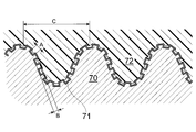
- a chemical treatment corresponding to the type of the metal alloy is performed to obtain a surface such as the following (1) to (3). That is, (1) A surface having a roughness on the order of microns, which is an uneven surface with a height difference of about half of the period in a period of 1 to 10 ⁇ m, (2) The inner wall surface of the recess is a fine uneven surface with a period of 10 to 500 nm, most preferably with a period of 50 to 80 nm. (3) The surface should be covered with a thin layer of a ceramic hard phase, specifically covered with a thin layer of an environmentally stable metal oxide or metal phosphate, It is. Assuming that the liquid resin composition has infiltrated into such a metal alloy and is hardened after the intrusion, it is a simple idea that the metal alloy substrate and the cured resin are bonded very firmly.
- thermoplastic resin with this new NMT theory.
- a hard and highly crystalline thermoplastic resin composition that can slow down the crystallization and solidification rate during rapid cooling is injected, the resin composition injected into the injection mold is cooled to a temperature below the melting point. Even for a while, it is in a supercooled liquid state. Therefore, if the metal alloy is inserted in advance into the injection mold, it can easily penetrate into the recess of (1).
- the joining method can be changed in the same way as the new NMT theory. That is, first, a resin molded product is prepared by a method such as injection molding using a resin composition mainly composed of a hard highly crystalline resin as a raw material. On the other hand, a metal alloy piece satisfying the above (1) to (3) is prepared and heated with a hot plate or the like. It is assumed that the resin molded product is pressed against the heated metal alloy piece. When the temperature of the metal alloy piece is higher than the melting point of the resin composition, the resin composition melts on the contact surface.
- the bonding mechanism of the new NMT theory is correct, it can be expected that bonding using a one-component thermosetting adhesive will produce a very strong bond. That is, the liquid resin approaches the surface-treated metal alloy according to the new NMT theory and penetrates into the concave portion of the micron order, and further penetrates into the concave portion of the fine unevenness on the inner wall surface of the concave portion to a certain extent. This is because if it is hardened, the solidified resin cannot be removed from the recess due to the spike effect, and it is estimated that strong bonding can be obtained. However, depending on how much viscosity the liquid resin has in its environment (pressure, temperature), it is determined how much the resin can enter the gaps of the fine irregularities.
- the one-component adhesive is preferable because gelation does not progress during the coating and subsequent pre-curing operations, and the molecular diameter of the molecules constituting the resin component is small, so that it penetrates into the gaps between the fine irregularities in (2) to some extent. Because it is possible. Even in the case of a two-component thermosetting adhesive, the use of a metal alloy that has been surface-treated according to the NAT theory improves the bonding force, but often does not lead to a dramatic increase in bonding force. This is because most of the two-part adhesives start to gel from the moment the hardener component is added to the main liquid and mixed. As the gelation progresses, the resin component enters the gaps between the fine irregularities in (2). This is because there is less.
- phenol resin adhesives are commercially available, but many are added with a solvent, and are not solventless like many epoxy adhesives.
- the solvent is volatilized and solidified by allowing it to stand for a while after coating, and when the pressure is reduced / returned to normal pressure at a medium temperature of 50 to 70 ° C., the phenol resin after the solvent volatilizes and the viscosity becomes 10 Pa seconds. Since the liquid has changed to a viscous liquid, the air on the metal uneven surface can be extracted.
- unsaturated polyester adhesives are not commercially available, but there are many unsaturated polyester components used to make glass fiber reinforced plastics (hereinafter referred to as “GFRP”).
- GFRP glass fiber reinforced plastics
- organic peroxide for heat curing that mixes with this, and when both are mixed with an appropriate recipe, the gelation does not proceed immediately and the gelation solidifies by raising the temperature. Therefore, it can be used substantially as a one-component thermosetting adhesive.
- the above-mentioned metal alloy is not the only material to be bonded to the metal alloy.
- a phenol resin adhesive is used as an adhesive, friction materials and abrasives that use phenol resin as a matrix are also easily bonded.
- an epoxy adhesive is used as an adhesive, an epoxy resin is used as a matrix.
- Carbon fiber reinforced plastic hereinafter referred to as “CFRP”) is also easily bonded.
- Patent Document 3 A similar technique has been reported in the past for injection joining using a metal alloy and a thermoplastic resin (Patent Document 3). It should be noted that the technique described in Patent Document 3 is not an injection joining technique but a technique that uses the relationship between the metal linear expansion coefficient and the resin molding shrinkage ratio in the injection molding technique.
- the metal rod portion is a resin molded product when the molded product is released from the mold and allowed to cool. It can be tightened from the part. This is because even if the linear expansion coefficient of the metal is large, it is 1.7 to 2.5 ⁇ 10 ⁇ 5 ° C. ⁇ 1 of aluminum alloy, magnesium alloy and copper alloy, and even if it is lowered from the mold and cooled to room temperature. The degree of shrinkage is only 0.2 to 0.3% at a linear expansion coefficient of about 100 ° C.
- one of the resins has a molding shrinkage of about 1% for PPS and 0.5% for PPS with glass fiber. Even with a resin with increased filler, the resin part is always better than the metal part after injection molding. Is greatly shrunk. Therefore, if a shape product that has a metal part in the center and penetrates the resin part is manufactured by injection molding with an insert, it is possible to manufacture an integrated product in which the metal part is not easily removed due to the tightening effect due to molding shrinkage of the resin part. it can.
- the manufacturing method of such a clamped metal / resin integrated product is a conventionally known method, and there is a handle of an oil stove as a similar molded product.
- a thick steel wire with a diameter of about 2 mm is inserted into an injection mold to inject heat-resistant resin.
- the wire is notched (knurled) so that the resin does not move.
- the uneven processing is made smart instead of the physical processing method to the chemical processing method, and the unevenness is made slightly finer, and the resin side is made of a hard and crystalline resin for grip. It is the feature that raised the effect to do.
- gas leakage that occurs along the metal rod is greatly suppressed by the disclosed technique, but there is no description regarding the bonding force.
- Patent Document 1 and Patent Documents 4 to 8 does not require any resin fastening effect.
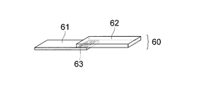
- An intense force is required to break a shaped product in which flat plate shapes are joined.
- the technique for increasing the bonding strength of the present invention is also characterized by using a high-hardness crystalline resin composition that crystallizes and solidifies after a long supercooling time during rapid cooling.
- the linear expansion coefficient of the thermoplastic resin composition can be made considerably low by containing a large amount of reinforcing fibers such as glass fibers and carbon fibers, that is, fillers.
- Patent Documents 8 and 15 examples using general steel materials are described.
- the present inventors have surface-treated cold-rolled steel and hot-rolled steel as the most general structural steel materials, which are suitable for injection bonding and adhesive bonding, in short, in a shape conforming to the new NMT theory and NAT theory. .
- Zinc-based plated steel sheets and aluminum plated steel sheets are used for building materials that are maintenance-free for 10 to 20 years. Pre-coating is applied to these steel sheets with 1 coat, 2 coats, and in some cases 3 coats. Steel plates (also called color steel plates and color iron plates) are also used in large quantities due to their good corrosion resistance and good post-processing properties.
- steel plates also called color steel plates and color iron plates
- aluminum plated steel sheets are used for stove covers, high temperature gas exhaust pipes and the like because they have excellent corrosion resistance at high temperatures. From the above, the present inventors have advanced research and development on zinc-plated steel sheets and aluminum-plated steel sheets in addition to general steel materials.
- the present inventors applied the NAT theory to further improve the bonding strength between the aluminum plated steel sheet and its upper coat layer, or the epoxy adhesive or phenolic resin that is the original purpose of the NAT theory.
- Research and development proceeded on whether an adhesive and unsaturated polyester resin-based adhesive could provide a strong adhesive force not previously recognized, or whether injection bonding using PBT or PPS resin based on the new NMT theory is possible.
- the present invention was an important research and development for confirming the NMT theory, the new NMT theory, and the NAT theory as described above, but the conclusion was unexpected. That is, although the object of the present invention was completely obtained, the surface shape of the treated aluminum plated steel sheet that achieved this object was different from the conditions required by the NMT theory, the new NMT theory, and the NAT theory. This can be understood by referring to FIGS. 13 and 14, which are the results of electron microscope observation. Such a surface shape that is difficult to define is the second after the ⁇ - ⁇ titanium alloy for the inventors.
- the white large three-dimensional object has a complicated shape with an under structure, If the amine compound is adsorbed even in small irregularities, the injection resin will firmly enter into the gaps formed by the recesses and the roots of the protrusions and solidify according to the NMT theory. Therefore, although it is different from the surface shape defined by the NMT theory, the new NMT theory, and the NAT theory, it is possible to expect a similar result.
- thermoplastic resin composition is injection-bonded to an aluminum plated steel sheet, and a thermoplastic resin composition molded product is pressure-bonded to the aluminum plated steel sheet, or between the aluminum plated steel sheets or between the aluminum plated steel sheets. It is related to the practical technology to obtain a strong steel plate resin integrated product by adhesively bonding to other adherends, and the corrosion resistance of the aluminum plated steel plate is made by coating the aluminum plated steel plate and bonding firmly There is a problem that further enhancement is desired.
- a composite part in which an aluminum-plated steel sheet material and a resin molded product are firmly integrated can be manufactured, it can be preferably used in building material-related parts mainly used outdoors. Further, if the corrosion-resistant coating layer can be strongly bonded to the aluminum-plated steel sheet, it not only leads to an improvement in the corrosion resistance of the aluminum-plated steel sheet, but also helps to improve the performance of the pre-coated steel sheet using the aluminum-plated steel sheet.
- the object of the present invention is to provide a technique for solving these problems.
- the present invention has been made to solve the above-mentioned problems, and the composite of steel and resin according to claim 1 of the present invention has a stone-shaped shape with a diameter of about 0.3 ⁇ m or more or a short diameter of 0.3 ⁇ m or more.
- Irregularly shaped three-dimensional projections having a major axis of several ⁇ m or more are scattered on the plateau, and shallow depressions with a diameter of 20 to 50 nm are adjacently distributed on the plateau.
- the surface of the three-dimensional projection is mainly made of a ceramic material containing silicon, and the plate-like portion is mainly composed of a surface shape that occupies 30 to 50% of the area of the plate-like portion.
- the composite of a steel material and a resin according to claim 2 of the present invention has a stone roller shape with a diameter of about 0.3 ⁇ m or more, or an irregular three-dimensional protrusion with a minor axis of 0.3 ⁇ m or more and a major axis of several ⁇ m or more.
- the portion covered with the shallow concave portions having a diameter of 20 to 50 nm adjacently distributed on the plain portion covers 30 to 50% of the area of the plain portion.
- a predetermined chemical reaction with the aluminum plated steel sheet, the surface shape of the surface and the surface of the three-dimensional protrusion is a ceramic material mainly containing silicon, and the plain portion is a ceramic material mainly containing aluminum.
- the steel material having corrosion resistance according to claim 3 of the present invention has a stone-like shape having a diameter of about 0.3 ⁇ m or more, or irregular three-dimensional projections having a minor axis of 0.3 ⁇ m or more and a major axis of several ⁇ m or more. It is a shape scattered on the surface, and on the plain portion, a portion covered with shallow recesses having a diameter of 20 to 50 nm adjacently occupies 30 to 50% of the area of the plain portion.
- the surface of the three-dimensional protrusion is made of a ceramic material mainly containing silicon, and the plain portion is a ceramic material mainly containing aluminum.
- cured are included at least.
- the composite of steel and resin according to claim 4 of the present invention is formed by a chemical reaction including a step of chemically etching with a weakly basic aqueous solution of at least PH 9-11, and the average length (RSm) of the contour curve element is 3 Molded product of steel sheet shape, which is originally an aluminum plated steel sheet, and a resin composition mainly composed of a hard and crystalline thermoplastic resin, having a maximum height roughness (Rz) of 1 to 8 ⁇ m and a maximum height roughness (Rz) of 1 to 20 ⁇ m And are directly joined.
- the composite of steel and resin according to claim 5 of the present invention is formed by a chemical reaction step including a step of chemically etching with a weakly basic aqueous solution having a pH of 9 to 11, and has an average length (RSm) of contour curve elements.
- a steel plate shaped article originally made of an aluminum plated steel sheet having a maximum height roughness (Rz) of 3 to 20 ⁇ m and a maximum height roughness (Rz) of 1 to 8 ⁇ m, an adhesive layer in which a one-component thermosetting adhesive is cured, and the adhesion And an adherend which is a metal alloy or resin shaped product joined to the steel plate shaped product by an agent layer.
- the steel material having corrosion resistance according to claim 6 of the present invention is formed by a chemical reaction including a step of chemically etching with a weakly basic aqueous solution having a pH of 9 to 11, and the average length (RSm) of the contour curve element is 3 to 20 ⁇ m. And the maximum height roughness (Rz) of 1 to 8 ⁇ m, which is a steel plate-shaped product that is originally an aluminum plated steel plate, and a coating layer obtained by curing a one-component thermosetting coating material.
- the steel and resin composite according to claim 7 quoting any one of claims 1 or 4 is characterized in that the hard and crystalline thermoplastic resin is polybutylene terephthalate resin, polyphenylene sulfide resin, polyamide It is either a resin or a resin composition mainly composed of a liquid crystal polymer.
- the composite of a steel material and a resin according to claim 8 which refers to any one of claims 1 or 4 of the present invention is characterized in that the resin composition containing the hard crystalline thermoplastic resin as a main component is polybutylene terephthalate.
- the resin composition containing the hard crystalline thermoplastic resin as a main component is polybutylene terephthalate.
- the resin component of one resin composition is a resin composition having a polybutylene terephthalate resin as a main component and a polyethylene terephthalate resin and / or a polyolefin resin as a subsidiary component
- the resin component of the second resin composition is a polyphenylene sulfide resin.
- the aliphatic polyamide resin to the bromide resin as a main component is obtained as a resin composition is a minor component.
- the first resin composition is 70 to 97% by mass of polybutylene terephthalate resin, said polyethylene terephthalate resin and / or polyolefin
- the amount of the system resin is 3 to 30% by mass.
- the second resin composition has a polyphenylene sulfide resin content of 70 to 97% by mass and the polyolefin resin content of 3 to 30% by mass. %.
- thermosetting adhesive is a phenol resin, an epoxy resin, or an unsaturated polyester adhesive. It is intended to be.
- a steel / resin composite according to claim 12 quoting any one of claims 2 or 5 is used for an abrasive or friction material in which the resin-made adherend contains a phenol resin.
- the composition is a fiber reinforced plastic containing an epoxy resin, or a fiber reinforced plastic containing an unsaturated polyester resin.
- thermosetting coating material is mainly composed of an epoxy resin. Is.
- thermoplastic crystalline resin composition thermosetting adhesive, or the like.
- the thermosetting coating material is selected from 0 to 60% by weight of glass fiber, carbon fiber, aramid fiber, carbon nanotube, other reinforcing fiber, calcium carbonate, magnesium carbonate, silica, talc, clay, and glass powder 1 It contains more than seed material.
- a method for producing a composite of steel and resin according to claim 15 of the present invention includes a shaping step of shaping an aluminum-plated steel plate by mechanical processing, and chemically etching the shaped steel with an acid-basic aqueous solution.
- a method for producing a steel / resin composite a shaping step of shaping an aluminum plated steel plate by mechanical processing, and chemical etching of the shaped steel material with an acid-basic aqueous solution.
- a step of finely etching the treated steel material with a weakly basic aqueous solution having a pH of 9 to 11, an insert step of inserting the steel material after the chemical reaction step into an injection mold, and the inserted base material A first resin composition comprising a polybutylene terephthalate resin as a main component and a polyethylene terephthalate resin and / or a polyolefin liquid resin as a minor component; a second resin composition comprising a polyphenylene sulfide resin as a major component and a polyolefin resin as a minor component; Alternatively, a third resin composition containing an aromatic polyamide resin as a main component and an aliphatic polyamide resin as a subcomponent An injection bonding step of integrating the resin composition and the steel by injecting a is made of.
- a method for producing a composite of a steel material and a resin according to claim 17 of the present invention includes a shaping step of shaping an aluminum plated steel plate by mechanical processing, and chemically etching the shaped steel material with an acid-basic aqueous solution.
- a method for producing a composite of steel and resin according to claim 18 of the present invention includes a shaping step of shaping an aluminum plated steel plate by mechanical processing, and chemically etching the shaped steel with an acid-basic aqueous solution.
- the coated base material is housed in a sealed container, depressurized, and then infiltrated with an adhesive that performs an operation of applying pressure, and the steel material coated with the adhesive is made of metal or uncured thermosetting resin. It consists of a step of pressing and fixing the adherend and a curing and bonding step of heating the temporary integrated product to cure the adhesive component.
- a method for producing a corrosion-resistant steel material according to claim 19 of the present invention includes a shaping step of shaping an aluminum plated steel plate by mechanical processing, a step of chemically etching the shaped steel material with an acid-basic aqueous solution, It includes at least a step of finely etching the treated steel material with a weakly basic aqueous solution having a pH of 9 to 11, and a step of applying and curing a one-component thermosetting coating material on the base material after the chemical reaction step. .
- a method for producing a corrosion-resistant steel material according to claim 20 of the present invention includes a shaping step of shaping an aluminum plated steel plate by mechanical processing, a step of chemically etching the shaped steel material with an acid-basic aqueous solution, Finely etching the treated steel with a weakly basic aqueous solution having a pH of 9 to 11, applying a one-component thermosetting coating material to the substrate after the chemical reaction step, and applying the coating material
- the base material is stored in an airtight container, decompressed, and thereafter impregnated with a coating material that performs an operation of pressurizing, and a curing step of heating and hardening the steel material.
- the method for producing a corrosion-resistant steel material or a composite of a steel material and a resin according to claim 21 quoting any one of claims 15 to 20 of the present invention is such that the aqueous solution used for fine etching is at room temperature to 70 ° C.
- the basic substance used and added is one selected from hydrated hydrazine, ammonia, or water-soluble amine compounds.
- thermoplastic resin composition part and the aluminum-plated steel sheet part are integrated without being easily peeled off.
- a thermoplastic resin composition having a resin composition containing 70 to 97% by mass of PBT and 30 to 3% by mass of PET and / or polyolefin-based resin, or PPS 70 to 97 obtained by subjecting an aluminum-plated steel plate part to surface treatment according to the present invention.
- Manufactures a composite in which a thermoplastic resin composition having a resin composition containing 1% by mass and 3 to 30% by weight of a polyolefin resin, or a thermoplastic resin composition containing both an aromatic polyamide and an aliphatic polyamide is strongly injection-bonded. can do.
- the composite of the present invention is a thermoplastic resin composition containing PBT, PPS, polyamide, liquid crystal polymer, etc., and once a resin molded product is produced by an injection molding method, an aluminum plated steel plate part is provided with a surface according to the present invention. A process is given. And the said steel plate piece after surface treatment is heated. A metal resin composite can be manufactured by pressing and pressing the resin molded product to the heated steel plate piece.
- the one-component thermosetting adhesive and the aluminum-plated steel sheet material are extremely strongly bonded.
- the aluminum plated steel plate parts, aluminum plated steel plate parts and other metal alloy parts, or aluminum plated steel plate parts using the surface treatment according to the present invention for the aluminum plated steel plate parts And a metal resin composite in which CFRP or GFRP is strongly bonded can be produced.
- the present invention applies the fact that the one-component thermosetting coating material and the aluminum plated steel sheet can be bonded very strongly, and contributes to the improvement of the performance of the aluminum plated steel sheet and the precoated steel sheet having excellent corrosion resistance.
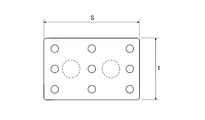
- die block diagram which showed typically the process of manufacturing the composite_body
- 1 schematically shows a composite by injection joining of metal and resin. It is a figure which shows the example of a shape of resin boss molded products. It is the schematic diagram shown so that it may understand that a metal mold
- FIG. 1 It is a figure which shows the example of the components which the resin boss
- An aluminum-plated steel sheet “MSA120 (Tokyo, Japan, Nisshin Steel Co., Ltd.)” obtained by surface treatment using an aqueous caustic soda solution as an etching agent and a monohydric hydrazine aqueous solution as a fine etching agent. It is the electron micrograph of the surface 100,000 times.
- the steel plate base material in the present invention is a molten aluminum alloy-plated steel plate in detail. It is commercially available under the name of “aluminum plated steel sheet”.
- the normal method for producing this steel material is to continuously immerse the steel plate in a high-temperature tank in which molten aluminum alloy is stored, using the coil steel plate material as a raw material, and wind it again to produce it. Therefore, although the term “steel plate” is often used in the description of the invention, it is a matter of course that a steel material obtained by similarly dipping in a molten aluminum alloy is also an object of the present invention even if it is other than a plate shape.
- Aluminum alloys used in the manufacturing process of aluminum plated steel sheets contain silicon in addition to aluminum, and some iron. Although details are based on catalogs and technical books, it is an example of elemental analysis of the aluminum surface layer of a commercially available aluminum-plated steel sheet, and it is said that the metal content was 77% aluminum, 8% silicon, and 15% iron. Further, the inclusion of silicon facilitates the formation of an intermediate layer between the surface aluminum layer and the steel material that is the base material, and as a result, the bonding force between the steel material and the aluminum alloy layer is said to increase.
- the iron atom content obtained in the above analysis was contained in the original molten aluminum alloy, whether it was transferred from the steel after immersion in the molten aluminum alloy, whether iron from both sides were mixed.
- the present inventors do not know to what extent the analysis itself was made by taking a part of the plating layer because it is not a manufacturer of the aluminum plating steel sheet.
- the inventors themselves have not performed surface analysis by XPS of the aluminum-plated steel plate raw material, and whether the iron atom content reaches the surface, or approximately ten and several percent of iron including the surface is almost even. I do not know the detailed image of whether it is contained or not.
- the aluminum-plated steel sheet used by the present inventors was used for experiments within 6 months after the manufacture by a domestic manufacturer.
- the steel is an aluminum alloy with a very low silicon and iron content by means of electroplating or explosive bonding, the surface of which is an aluminum alloy close to the composition of the aluminum alloy for extension, which is the injection of resin.
- Patent Documents 1, 2, 3, 9, 10 and the like should be referred to, not the present invention.
- the degreasing process is a process in which machining oil and finger grease are generally attached to metal alloy parts that have been machined or the like, so that they are immersed in an aqueous solution containing a surfactant and washed with water.
- a general metal degreasing agent in which a surfactant is dissolved. That is, a degreasing agent for aluminum, a degreasing agent for magnesium alloy, a degreasing agent for iron, a degreasing agent for stainless steel, and the like can be suitably used.
- an aqueous solution of a strong base such as caustic soda or an aqueous solution of a non-oxidizing acid such as a halogen acid is preferably used.
- Either acid or base may be used, but it is preferable to use both in turn. That is, there is some induction period before the etching reaction starts in earnest after the steel material after the above process is immersed, whether it is an acidic solution or a basic solution. This is because the outermost layer of the aluminum plated steel sheet is covered with a natural oxide layer of an aluminum alloy. Therefore, the induction period changes depending on the state of the natural oxide layer. For this reason, even if an acid-basic aqueous solution having a constant concentration and a constant temperature is used, the etching level is hardly constant. *
- the etching process is shown in the experimental examples, but by adjusting the acid-base concentration, liquid temperature, and immersion time of the etching solution, and by observing the roughness of the scanning probe microscope, Japanese Industrial Standard (JIS) B0601: 2001 (ISO 4287) )
- JIS Japanese Industrial Standard
- the average length (mean length) of profile element RSm is 1-10 ⁇ m and the maximum profile curve height (roughness profile) element height), that is, a rough condition such that the maximum height roughness (maximum hight of roughness profile) Rz is 0.5 to 5 ⁇ m.
- the injection bonding force specifically, the one with a large rupture force of an integrated product obtained by performing an injection bonding test using a PPS resin, which will be described later, is used as a good index.
- the roughness was measured for those having a high.
- the purpose can be achieved by immersing in an aqueous solution of PH 9-11 at a liquid temperature of normal temperature to 70 ° C. for 1 to 30 minutes.
- Ammonia water has a strong odor and can only be used at room temperature. Even if it is used at a maximum concentration of about 25%, it needs to be immersed for 20 to 30 minutes. This is because the basicity is slightly weak.
- the present inventors consider that it is most preferable to use monohydric hydrazine. It is preferable to use an aqueous solution with a concentration of several percent, 50 to 60 ° C., and a pH of about 9.5 to 10.2, and the odor is not strong. By dipping in such a weakly basic aqueous solution, the aluminum-rich surface is finely etched so that the concave portion with a diameter of 30 to 50 nm covers the entire surface, and at the same time, the amine compound used here, hydrazine, is chemically adsorbed on the surface.
- FIGS. 13 and 14 show a 10,000 times electron micrograph and FIG. 14 shows a 100,000 times electron micrograph. Although it is FIG. 13, it represents the mysterious surface of the plain shape in which a huge three-dimensional object and many small stones are scattered.
- the large white solid shapes that are difficult to express and the scattered stone-shaped ones show a large amount of silicon, a small amount of aluminum, and a small amount of iron according to the analysis of the EDX function by another analytical electron microscope. It seems to be made of a silicon oxide ceramic material mainly containing silicon.
- the plain was found to be a ceramic layer mainly composed of aluminum oxide because the aluminum image had the strongest aluminum image and silicon and iron were found by EDX analysis. Further, from FIG. 14 in which the plain portion is enlarged, a circular pattern with a diameter of 30 to 50 nm is recognized in addition to stone rollers in an area of about 1/3, but not the entire surface.
- the inventors of the present invention performed injection bonding of a PPS resin (PPS composition (1) according to Preparation Example 1 in Examples) to a surface-treated aluminum plated steel sheet, and measured the bonding strength of the obtained integrated product.
- the roughness of the aluminum-plated steel sheet that gave sufficient joint strength in these experiments was measured with a scanning probe microscope.
- RSm of the contour curve element of 3 to 20 ⁇ m
- Rz maximum height roughness
- the surface-treated aluminum plated steel sheet all of the detected aluminum atoms were trivalent. This is because the thickness of the natural oxide layer of aluminum is at least 2 nm or more, and is thicker than the natural oxide layer of commercially available aluminum alloys such as A5052. From the above, it can be said that the surface layer of the aluminum-plated steel sheet after processing is covered with a hard ceramic material as seen in the electron microscope, so the metal alloy referred to in the new NMT theory and NAT theory. Meets the surface chemical conditions.
- Thermoplastic resin composition for injection joining is a first resin composition mainly composed of PBT, which is a crystalline resin, which is directly joined to the aluminum-plated steel sheet by injection molding.
- the second resin composition containing PPS as a main component or the third resin composition containing aromatic polyamide as a main component.
- the resin component of the first resin composition is a resin composition containing PBT as a main component and PET and / or polyolefin resin as a subcomponent.
- the resin component of the second resin composition is a resin composition having PPS as a main component and a polyolefin resin as a subsidiary component.
- the resin component of the third resin composition is a resin composition having an aromatic polyamide as a main component and an aliphatic polyamide as a subsidiary component.
- the first resin composition is 70 to 97% by mass of PBT, 3 to 30% by mass of the PET and / or polyolefin resin
- the second resin composition is 70 to 97% by mass of PPS and the polyolefin resin is
- the amount of the third resin composition is preferably 50 to 100% for the aromatic polyamide and 0 to 50% for the aliphatic polyamide. If it is out of this range, the injection joining force is greatly reduced.
- the high-hardness crystalline resin composition which is a resin composition, includes at least one filler selected from glass fiber, carbon fiber, aramid fiber, other reinforcing fibers, calcium carbonate, magnesium carbonate, silica, talc, clay, and glass powder.
- PPS or PBT containing 20 to 60% by mass of the material as a whole is preferable.
- the linear expansion coefficient of the resin molded product is set to 2 to 3 ⁇ 10 ⁇ 5 ° C. ⁇ 1, and the internal expansion at the joint surface caused when the temperature changes by bringing the linear expansion coefficient close to the metal alloy is reduced. This is to keep the level small.
- This composite production method is an injection molding method performed after inserting a metal alloy material part into a mold, and is performed as follows. Prepare a mold for injection molding, open the mold, insert the steel shape obtained by the above-mentioned treatment into one of the molds, close the mold, and improve PBT, improved PPS, or improved aromatic polyamide The composite is produced by injecting and solidifying the thermoplastic resin composition and then releasing the mold.
- the mold temperature is particularly preferably 100 ° C. or higher, more preferably 120 ° C. or higher for PBT or PPS-based resins because it has little influence on the resin strength after solidification and is excellent in production efficiency of the composite.
- the injection temperature, injection pressure, and injection speed are not particularly different from those of normal injection molding, but it is preferable to increase the injection speed and injection pressure.
- Thermoplastic resin composition for pressure fusion can be a resin composition mainly composed of a hard highly crystalline resin.
- PBT, PPS, aromatic polyamide, aliphatic polyamide, liquid crystal polymer, polyetheretherketone (hereinafter referred to as “PEEK”), etc. can be used as resin types.
- PEEK polyetheretherketone
- the above-described thermoplastic resin for injection joining that is, PBT, PPS and aromatic polyamide resins improved for injection joining can be used.
- any hard and highly crystalline resin can be used as long as it has a wider range than the thermoplastic resin for injection joining described above.
- PBT, PPS, polyamide resin and the like are preferable because their melting points are not too high.
- the resin composition containing these as a resin component includes at least one filler selected from glass fiber, carbon fiber, aramid fiber, other reinforcing fiber, calcium carbonate, magnesium carbonate, silica, talc, clay, and glass powder. It may be contained in an amount of 20 to 60% by mass of the whole composition.
- the liquid crystal polymer may contain 0 to 50% of the filler. This is because the linear expansion coefficient of the resin molded product is lowered by including these fillers.
- the resin component of the resin composition used in this composite manufacturing method is a hard, highly crystalline resin, specifically, PBT, PPS.
- Polyamide, liquid crystal polymer and the like are preferable.
- Improved PBT, PPS, and aromatic polyamide resin compositions that can be suitably used for injection joining also fall into these categories and are of course preferred for use.
- Glass fiber and other fillers are compounded to form a resin composition, and this is used as a raw material to be subjected to an injection molding machine to produce a resin molded product.
- the surface-treated aluminum-plated steel sheet is heated to a temperature equal to or higher than the melting point of the resin composition to be joined using a hot plate, hot air dryer, etc. Press. Even if it is above the melting point, it is possible to carry out the following operations at a temperature as high as several tens of degrees Celsius above the melting point.
- the steel plate part is heated to a predetermined temperature.
- the heated steel plate part is once transferred onto the heat insulating plate, and the prepared resin molded product is pressed against the placed steel plate piece.
- the bottom surface of the pressed resin part melts, and then the heat disperses and crystallizes and solidifies again.
- the molten resin enters the recesses on the surface of the steel sheet, and after entering, is cooled again, solidified, and joined.
- thermosetting adhesive that is liquid at the time of application and has few macromolecules (gelling molecules) is desired from the NAT theoretical viewpoint. More specifically, it penetrates into recesses with a period of several ⁇ m on the surface of a metal (aluminum plated steel plate) and further penetrates into the gaps of fine irregularities with a period of several tens to several hundreds of nanometers existing in the recesses. Therefore, it is desirable that the viscosity of the liquid is at most about 10 or more Pa seconds or less.
- thermosetting adhesive Even if it is a two-component thermosetting adhesive, the gelation temperature is high, the gelation rate near room temperature is very slow even after mixing the curing agent, and the viscosity range of the mixture is as described above. It is obvious that it is preferable for use if it is less than the above. Epoxy-type, phenol resin-type, and unsaturated polyester-type adhesives can be used. Many of the former two are commercially available with excellent adhesive ability.
- an organic peroxide having a very high decomposition temperature can be used as a curing agent.
- alkyd type and vinyl ester type in unsaturated polyester, but the adhesive strength itself is stronger using vinyl ester type, especially vinyl ester type unsaturated polyester made from epoxy resin and methacrylic acid.
- epoxy adhesive will be described in more detail.
- Many commercially available one-part epoxy adhesives use bisphenol-type epoxy resins, glycidylamine-type epoxy resins, polyfunctional polyphenol-type epoxy resins, alicyclic epoxy resins, etc. as epoxy resins, and dicyandiamide or imidazoles as curing agents. Is added. These can have a relatively low adhesive viscosity and are easy to apply, but have a slightly lower heat resistance than the types described below.
- Viscosity paste or solid Although there is a feature that the heat resistance of the cured product is high, from the viewpoint of the present invention, the viscosity is too high and it is difficult to perform a post-operation after the application (a work for soaking into the metal surface).
- Such an adhesive composition can be used by adding a solvent that does not participate in the polymerization reaction at all.
- thermosetting adhesives from epoxy resins and acid anhydrides are preferably used it can.
- this type is not commercially available. The reason is that gelation proceeds at a low speed after mixing at room temperature. Therefore, it is difficult to put a mixed product on the market from the viewpoint of quality assurance.
- companies that require adhesives usually purchase epoxy resins and acid anhydrides, compound them in-house, and use them on their own.
- thermosetting adhesive Adhesives of epoxy type, phenol resin type and unsaturated polyester type can be preferably used. Many epoxy-based and phenolic-resin-based ones having excellent adhesive ability are commercially available. It must be liquid at the time of application. A high-viscosity adhesive that is solid at room temperature can also be reduced to a viscosity level that can be said to be a liquid of several tens of Pa-seconds at 50 to 80 ° C. It is preferable to use such a phenomenon. Since such a high-viscosity adhesive is an epoxy-based adhesive, the main points when using epoxy bonding will be described.
- a large container such as a desiccator that can be operated to reduce pressure. Place these containers in a warm air dryer for approximately 1 hour to keep warm.
- a steel plate component subjected to the above-described surface treatment is prepared, and an adhesive is applied (applied) to a necessary portion thereof.
- the desiccator is taken out from the hot air dryer, the steel plate pieces coated with the adhesive are arranged in the desiccator, and the lid is covered to reduce the pressure from several tens mmHg to several mmHg with a vacuum pump. After leaving for a while under reduced pressure, return to normal pressure.
- CFRP Carbon fiber reinforced plastic
- thermosetting coating material A coating material that coats an aluminum plated steel plate and adheres strongly to improve corrosion resistance will be described. Any epoxy resin, phenol resin, unsaturated polyester resin or the like can be used as a coating material that basically improves the corrosion resistance as long as it is heated and gelled and cured. Of these, epoxy-based coating materials have the highest adhesive strength, and moreover, epoxy-based coating materials definitely have high adhesive strength in the temperature range near room temperature, so epoxy-based coating materials are the best way to produce the most corrosion-resistant steel materials. The use of a coating material is preferred. Therefore, an epoxy coating material will be described.
- the present inventors also used a commercially available epoxy paint for the test, but the resin adhesive “EP106 (manufactured by Cemedine)” diluted with a solvent was also used for the test as a self-made coating material.
- This adhesive is a one-component thermosetting epoxy adhesive in which dicyandiamide is already blended as a curing agent, and has a viscosity of about 10 to 20 Pa seconds at room temperature.
- FIGS. 1 and 2 are diagrams relating to injection joining of a thermoplastic resin
- FIG. 1 is a sectional view schematically showing a section of an injection mold used in the examples.
- FIG. 1 shows a state in which the mold is closed and injection molding is performed.
- FIG. 2 is an external view showing the external appearance of a steel material-resin composite 7 molded by an injection mold.
- This injection mold is composed of a movable side mold plate 2 and a fixed side mold plate 3, and a resin injection part composed of a pinpoint gate 5, a runner and the like is formed on the fixed side mold plate 3 side.
- the composite 7 is molded as follows. First, the movable mold plate 2 is opened, and the steel plate piece 1 is inserted into a cavity formed between the movable mold plate 2 and the fixed mold plate 3. After the insertion, the movable side template 2 is closed to the state before injection in FIG. Next, the molten resin composition is injected through the pinpoint gate 5 into a cavity in which a steel piece is inserted.
- the resin composition 4 When injected, the resin composition 4 is resin-molded by filling the cavity while being joined to the steel sheet piece, and a composite 7 in which the metal and the resin are integrated is obtained.
- the composite 7 has a joint surface 6 between the steel plate piece 1 and the resin composition 4, and the area of the joint surface 6 is 5 mm ⁇ 10 mm. That is, the area of the bonding surface 6 is 0.5 cm 2 .
- FIGS. 3, 4, 5, 6, 7, and 8 are diagrams relating to the pressure fusion bonding of thermoplastic resins
- FIG. 3 shows the thermoplastic resin used in the experimental example. It is the figure which showed typically the shape of the injection molded product.
- FIG. 4 shows that the resin molded product has a boss shape, but the shape is designed so that the center of the bottom of the boss protrudes about 0.1 mm.
- the molding may be performed by a pin gate.
- FIG. 5 shows an example of a jig for making an integrated product in which two bosses are fused to a steel plate piece by pressure fusion.
- a steel piece 13 heated by a hot plate or the like is placed in a recess made on the heat insulating material 12, and a resin molded product 22 (the runner portion is cut from the boss shown in FIG. 3) set in the upper die 19 in advance.
- the upper die 19 is pressed against the lower die 11.
- the two-way cock 28 is opened, the line is connected to a vacuum pump that has been driven in advance, the whole system is under reduced pressure of several mmHg, and the four-way cock 27 is turned 90 degrees in a few seconds to bring the whole system to normal pressure. return.
- the bottom of the resin molded product that has been melted by touching the steel sheet piece is likely to enter the micron-order recesses on the steel material.
- the obtained integrated product is preferably annealed for about 1 hour if possible.
- the annealing temperature varies depending on the melting point of the resin composition, it is preferably about 150 ° C. for PBT and polyamides, and about 170 ° C. for PPS and the like.
- FIG. 6 shows the shape of a steel plate piece for producing a composite that can measure the bonding strength of the pressure-bonded product, and is used for the pressure-bonding test shown in FIG. A large number of screw holes are opened to prepare for the tensile test. Therefore, the integrated product 30 of the steel material and the resin shown in FIG. 7 is obtained in a series of experiments.
- FIG. 11 shows an example of a metal-to-metal adhesive bond including a steel sheet piece according to the present invention, which is also used in the examples.
- the metal piece is 45 mm ⁇ 18 mm, and the bonding surface is an area of 0.5 to 0.6 cm 2 of 18 mm ⁇ about 3 mm. Used to measure the shear breaking force after tensile breaking.
- one of the metal pieces can be bonded with an adhesive instead of an aluminum-plated steel plate piece instead of another kind of metal piece.
- the multi-metal pieces are processed for the same purpose as the present invention, that is, aluminum alloys, magnesium alloys, copper alloys, titanium alloys, stainless steels, general steels, etc. processed based on the NAT theory, it is particularly intense. The bonding force can be observed.
- FIG. 9 and FIG. 10 show the manufacturing jig of the integrated product for measuring the adhesive strength of the steel plate and CFRP used by the present inventors, the situation of its use, and the obtained integrated product. The shape was shown.
- Reference numerals 42, 45, and 45 in FIG. 9 are iron molds that are combined.
- 57 is a polyethylene film cut into a rectangular shape, and two sheets are overlapped to form a release film.
- 51 is a 1 mm-thick steel plate
- 53 and 56 are spacers made of polytetrafluoroethylene resin (hereinafter referred to as “PTFE”)
- 52 is a carbon fiber fabric and an epoxy-based adhesive soaked therein, in short, CFRP prepreg. is there.
- PTFE polytetrafluoroethylene resin
- the entire assembly as shown in FIG. 9 is installed in a hot air dryer, and several hundred g of weight 58 is placed on 55. Leave it alone. After curing and allowing to cool, when the weight 58, the blocks 55 and 53, the film 54, and the pedestal 48 are removed and the mold 42 is pressed against the floor, the seat 45 is separated from the mold 42 and is integrated with the release film 57. (FIG. 10) can be taken out. The film can be peeled off if necessary
- This photoelectron analyzer is an “AXIS-Nova (product name)” in the form of observing a surface with a diameter of several ⁇ m up to a depth of several nanometers (UK, Kratos Analytical / Kyoto, Japan, Shimadzu Corporation) Made).
- SEM scanning electron microscope
- JSM-6700F product name
- D EDX Observation by Analytical Electron Microscope “HF-3000S (product name)” (Tokyo, Japan, manufactured by Hitachi, Ltd.), which is an electron microscope (analytical electron microscope) with an EDX function, was used.
- This microscope is a scanning probe microscope that uses a probe with a sharp tip to move the surface of a substance so as to trace the surface state.
- SPM-9600 product name
- This scanning probe microscope “SPM-9600 (product name)” (Kyoto, Japan, manufactured by Shimadzu Corporation) was used.
- This tensile tester used “Model 1323 (product name)” (Tokyo, Japan, manufactured by Aiko Engineering Co., Ltd.) and measured the shear force at a pulling speed of 10 mm / min.
- Preparation Example 1 Preparation Example of PPS Composition A 50 liter autoclave equipped with a stirrer was charged with 6,214 g of Na 2 S ⁇ 2.9H 2 O and 17,000 g of N-methyl-2-pyrrolidone, under a nitrogen stream. While stirring, the temperature was gradually raised to 205 ° C., and 1,355 g of water was distilled off. After cooling the system to 140 ° C., 7,160 g of p-dichlorobenzene and 5,000 g of N-methyl-2-pyrrolidone were added, and the system was sealed under a nitrogen stream.
- the system was heated to 225 ° C. over 2 hours, polymerized at 225 ° C. for 2 hours, then heated to 250 ° C. over 30 minutes, and further polymerized at 250 ° C. for 3 hours.
- the mixture was cooled to room temperature and the polymer was separated by a centrifuge.
- the solid content was repeatedly washed with warm water and dried at 100 ° C. for a whole day and night to obtain PPS having a melt viscosity of 280 poise (hereinafter referred to as PPS (1)).
- PPS (1) was further cured at 250 ° C. for 3 hours under a nitrogen atmosphere to obtain PPS (hereinafter referred to as PPS (2)).
- the resulting PPS (2) had a melt viscosity of 400 poise.
- PPS composition (1) was obtained by melting and kneading at a cylinder temperature of 300 ° C. while feeding “made by sheet glass Co., Ltd.” from the side feeder so that the addition amount was 20% by mass.
- the obtained PPS composition (1) was dried at 175 ° C. for 5 hours.
- Preparation Example 2 Preparation of PPS Composition
- the PPS (1) obtained in Preparation Example 1 was cured at 250 ° C. for 3 hours in an oxygen atmosphere to obtain PPS (hereinafter referred to as PPS (3)).
- the resulting PPS (3) had a melt viscosity of 1800 poise.
- the obtained PPS (3) 5.98 kg and polyethylene 0.02 kg “Nipolon Hard 8300A (manufactured by Tosoh Corporation, Tokyo, Japan)” were uniformly mixed in advance with a tumbler. Thereafter, in the twin screw extruder “TEM-35B”, while supplying glass fiber “RES03-TP91” having an average fiber diameter of 9 ⁇ m and a fiber length of 3 mm from the side feeder so that the addition amount becomes 40% by mass, the cylinder temperature PPS composition (2) pelletized by melt-kneading at 300 ° C. was obtained. The obtained PPS composition (2) was dried at 175 ° C. for 5 hours.
- Preparation Example 3 Preparation of PPS Composition 7.2 kg of PPS (2) obtained in Preparation Example 1 and 0.8 kg of glycidyl methacrylate-ethylene copolymer “Bond First E (Tokyo, Japan, manufactured by Sumitomo Chemical Co., Ltd.) ) "Was previously mixed uniformly with a tumbler. Thereafter, in the twin screw extruder “TEM-35B”, while supplying glass fiber “RES03-TP91” having an average fiber diameter of 9 ⁇ m and a fiber length of 3 mm from the side feeder so that the addition amount becomes 20 mass%, the cylinder temperature A PPS composition (3) which was melt-kneaded at 300 ° C. and pelletized was obtained. The obtained PPS composition (3) was dried at 175 ° C. for 5 hours.
- Preparation Example 4 Preparation of PPS Composition 4.0 kg of PPS (2) obtained in Preparation Example 1 and 4.0 kg of ethylene-acrylic acid ester-maleic anhydride terpolymer "Bondyne TX8030 (Arkema, France) The product was uniformly mixed with a tumbler in advance. Thereafter, in the twin screw extruder “TEM-35B”, while supplying glass fiber “RES03-TP91” having an average fiber diameter of 9 ⁇ m and a fiber length of 3 mm from the side feeder so that the addition amount becomes 20 mass%, the cylinder temperature A PPS composition (4) pelletized by melt-kneading at 300 ° C. was obtained. The obtained PPS composition (4) was dried at 175 ° C. for 5 hours.
- PBT composition (2) obtained by melt-kneading and pelletizing at a cylinder temperature of 270 ° C. was supplied from a side feeder so that the addition amount was 30% by mass. The obtained PBT composition (2) was dried at 150 ° C. for 5 hours.
- Preparation Example 7 Preparation of PBT composition 6.0 kg of PBT resin “Torcon 1401X31 (Tokyo, Japan, Toray Industries, Inc.)” and PET resin “TR-4550BH (Tokyo, Japan, Teijin Chemicals)” 0.5 kg, ethylene-acrylic acid ester-maleic anhydride terpolymer 0.5 kg “Bondyne TX8030 (manufactured by Arkema, France)”, epoxy resin “Epicoat 1004” (Tokyo, Japan, Japan Epoxy Resin Co., Ltd.) 0.1 kg) was previously mixed uniformly with a tumbler.
- PBT composition (3) obtained by melt-kneading at a cylinder temperature of 270 ° C. and pelletizing was supplied from a side feeder so that the addition amount was 30% by mass. The obtained PBT composition (3) was dried at 150 ° C. for 5 hours.
- Example 1 Preparation of aluminum-plated steel sheet piece A 0.6 mm thick aluminum-plated steel sheet with chromate treatment "MSA120 (manufactured by Nisshin Steel Co., Ltd., Japan)" was cut into 18 mm x 45 mm rectangular pieces and metal The plate 1 was a steel piece. An aqueous solution containing 7.5% of an aluminum degreasing agent “NE-6 (manufactured by Meltex Co., Ltd., Japan)” was prepared in a tank at 65 ° C., and this aqueous solution was used as a degreasing aqueous solution. In addition, a 1% hydrochloric acid aqueous solution was prepared at 40 ° C.
- aqueous solution for preliminary acid cleaning was prepared in another tank to prepare an aqueous solution for preliminary acid cleaning.
- an aqueous solution containing caustic soda 1.5% in another tank was set to 40 ° C., and this was used as an etching solution.
- a 3% nitric acid aqueous solution at 40 ° C. was prepared in a separate tank for neutralization.
- a 3.5% concentration monohydric hydrazine aqueous solution at 60 ° C. was prepared in a separate tank for fine etching.
- the steel plate pieces were first immersed in a degreasing bath for 5 minutes and washed with water. Subsequently, it was immersed in the preliminary acid washing tank for 1 minute and washed with water. Subsequently, it was immersed in an etching tank for 0.75 minutes and washed with water. Subsequently, it was immersed in the neutralization tank for 1 minute and washed with water. Subsequently, it was immersed in the fine etching tank for 1 minute and washed with water. In addition, all the water washing used ion-exchange water. This was dried at 67 ° C. for 15 minutes to obtain a treated steel piece.
- the surface is rough
- the average unevenness period (average length of the contour curve element) RSm is 4 to 7 ⁇ m
- the maximum height roughness Rz is It was 1 to 3 ⁇ m.
- Example 2 Injection Joining The aluminum-plated steel plate piece prepared in Experimental Example 1 was taken out, and the one with a hole so that oil and the like would not adhere was picked with gloves and inserted into an injection mold. The mold was closed and the PPS composition (1) obtained in Preparation Example 1 was injected at an injection temperature of 310 ° C. The mold temperature was 140 ° C., and 20 integrated composites shown in FIG. 2 were obtained. The size of the resin part was 10 mm ⁇ 45 mm ⁇ 5 mm, and the bonding surface 6 was 0.5 cm 2 of 10 mm ⁇ 5 mm. On the day of molding, the sample was put into a hot air dryer at 170 ° C. for 1 hour, annealed, and then a tensile test was conducted one day later. The average shear breaking strength of 5 pieces was 23.5 MPa.
- Example 4 Injection Bonding Steel sheet produced in Experimental Example 1 except that the PPS composition (3) obtained in Preparation Example 3 was used instead of the PPS composition (1) obtained in Preparation Example 1.
- a composite was obtained using a piece in the same manner as in Experimental Example 2. The composite was annealed at 170 ° C. for 1 hour on the day of molding, and after 2 days, the composite was measured for shear breaking strength with a tensile tester. As a result, the average of 5 pieces was 21.1 MPa.
- Example 8 Injection Bonding Steel sheet produced in Experimental Example 1 except that the PBT composition (2) obtained in Preparation Example 6 was used instead of the PBT composition (1) obtained in Preparation Example 5.
- a composite was obtained in the same manner as in Experimental Example 5 using a piece. Annealing was performed at 150 ° C. for 1 hour on the day of molding, and two days later, the composite was measured for shear breaking strength with a tensile tester. As a result, the average of 5 pieces was 21.7 MPa.
- Example 9 Injection Bonding Steel sheet produced in Experimental Example 1 except that the PBT composition (3) obtained in Preparation Example 7 was used instead of the PBT composition (1) obtained in Preparation Example 5.
- a composite was obtained in the same manner as in Experimental Example 6 using a piece. The composite was annealed at 150 ° C. for 1 hour on the day of molding, and two days later, the composite was measured for shear breaking strength with a tensile tester. As a result, the average of the five pieces was 19.8 MPa.
- PPS composition obtained by 1 (1) (e) 6 nylon resin “B3EG7 (manufactured by Bayer SF, Germany)” containing 30% glass fiber, (f) aromatic polyamide containing 50% glass fiber
- the resin “Amilan CM3510G50 (Tokyo, Japan, manufactured by Toray Industries, Inc.)” and (g) liquid crystal polymer “Vectra A460 (Tokyo, Japan, manufactured by Polyplastics Corporation)” were used.
- the runner part of the obtained molded product (the protruding part connected from the gate part to the main body) was cut from the root with a nipper to prepare for the next experiment.
- the technical key is to adjust the bottom of the resin molded product so that it remains in a molten state for about 10 seconds.
- the molten resin soaks into the micron-order recesses on the surface of the steel sheet, and subsequent strong crystallization solidification produces a strong bond.
- a resin-metal integrated product as shown in FIG. 7 was obtained. This was placed in a hot air drier at 150 ° C. for 1 hour, annealed, and allowed to cool.
- the resin molded product was pulled and broken from the steel plate piece by the mechanism as shown in FIG. The results are shown in Table 1. Those that broke at 50 kgf or less were rated as x, and those that did not break were marked as ⁇ .
- Adhesion Epoxy adhesive “EP106 (Tokyo, Japan, manufactured by Cemedine Co., Ltd.)” was applied to the steel plate pieces according to Experimental Example 1 on the ends and placed in a desiccator. The internal pressure was reduced to 5 mmHg by reducing the pressure with a vacuum pump. The pressure was reduced to normal pressure every 2 minutes. Again, the decompression / return to normal pressure operation was performed three times in total, and the steel plate piece was taken out from the desiccator. The two steel plate pieces coated with adhesive were bonded to each other, that is, the shape shown in FIG. The adhesion area was 0.6 to 0.7 cm 2 . This fixed product was put into a hot air dryer and heated.
- the temperature was raised to 135 ° C. every 40 minutes, and then further raised to 165 ° C. and kept at this temperature for 30 minutes. It was allowed to cool, and after one week, it was pulled and ruptured, and its shear breaking strength was measured. As a result, it was 450 kgf / cm 2 (44 MPa), which was very strong.
- thermosetting resin as shown in Table 2 was prepared in order to prepare a prepreg.
- thermosetting resin composed of the components shown in Table 2 was mixed at room temperature and formed into a sheet with a roll.
- the obtained heat tree curable resin film is set in a prepreg machine and applied in a conventional manner from both sides of the carbon fiber “T-300 (manufactured by Toray Industries, Tokyo, Japan)” aligned in one direction as a reinforcing fiber.
- a prepreg adjusted to a resin content of 38% was obtained by pressure bonding under pressure.
- the fiber basis weight was 190 g / m 2 .
- PTFE spacer 53 and block 55 were placed and placed in a hot air dryer. Therefore, a 0.5 kg iron weight 58 was placed on the PFTE spacers, blocks 53 and 55, and the dryer was energized to raise the temperature to 135 ° C. The mixture was heated at 135 ° C. for 40 minutes, further heated to 165 ° C. over 5 minutes, held at 165 ° C. for 60 minutes, turned off, and allowed to cool with the door closed. On the next day, the product was taken out from the dryer and the molded product was released from the firing mold 1 and the polyethylene film was peeled off to obtain a composite 50 shown in FIG. The same operation was repeated to obtain an integrated product 50 that was a composite of eight steel plate pieces and CFRP.
- PTFE spacer 53 and block 55 were placed and placed in a hot air dryer. Therefore, a 0.5 kg iron weight 58 was placed on the PFTE spacers and blocks 53 and 55, and the dryer was energized to raise the temperature to 135 ° C. The mixture was heated at 120 ° C. for 1 hour, further heated to 165 ° C. over 10 minutes, held at 165 ° C. for 2 hours, turned off, and allowed to cool with the door closed. On the next day, the product was taken out from the dryer and the molded product was released from the firing mold 1 and the polyethylene film was peeled off to obtain a composite 50 shown in FIG. The same operation was repeated to obtain an integrated product 50 that was a composite of eight steel plate pieces and CFRP.
- thermosetting adhesive “EP106 (Tokyo, Japan, Cemedine Co., Ltd.)” 10 g and methyl ethyl ketone 10 g were mixed and completely dissolved to obtain an epoxy coating material manufactured in-house.
- Five pieces of the steel plate were placed on corrugated paper and the coating material made in-house was brush-painted. After being air-dried for a while, each of the cardboard papers was placed in a hot air dryer set to 135 ° C. for 30 minutes, the temperature was raised to 150 ° C., and the temperature was raised to 150 ° C. for 20 minutes to exit from the hot air dryer.
- the steel piece was turned upside down on the corrugated paper, and the coating material made in-house was brush-painted on this surface.
- the cardboard paper was placed in a hot air dryer set at 135 ° C. for 30 minutes, the temperature was raised to 165 ° C., and the temperature was raised to 165 ° C. and the hot air dryer was taken out. The one that was applied and baked later was defined as the surface.
- Example 19 Coating: Comparative Example Five sheets of aluminum-plated steel sheet “MSA120 (Tokyo, Japan, Nisshin Steel Co., Ltd.)” cut into 25 mm ⁇ 100 mm and having a 3 mm ⁇ hole at the end were prepared and tested. It was immersed only in the degreasing tank used in Example 1, then washed with water and dried at 67 ° C. for 15 minutes. Next, in the same manner as in Experimental Example 18, a front and back coating of an in-house manufactured epoxy coating material was performed in the same manner. The front and back sides were determined in the same manner as in Experimental Example 18.
- the plastic bag was removed every day to replenish the slightly volatilized water. After removing from the bucket and immersing in pure water for 15 minutes and rinsing away easily, it was placed in a hot air dryer at 67 ° C. for 30 minutes and dried.
- ⁇ By applying the present invention to various fields it is possible to improve the joining property, improve the efficiency, expand the application range, etc., and enable a new design method for manufacturing building materials and outdoor housing equipment. That is, a resin molded part having a complicated shape and an aluminum plated steel sheet part having a relatively simple shape can be manufactured by an automatic and efficient method (injection joining method, pressure fusion method) without an adhesive.
- the aluminum plated steel plate and FRP can be integrated via an unsaturated polyester adhesive, which is useful in the manufacture of outdoor products, that is, building materials and parts of housing equipment and structural materials.
- the long-term corrosion resistance of the aluminum-plated steel sheet can be further improved by applying the epoxy coating material, which is useful for improving the performance of the pre-coated steel sheet.
- CFRP is used as an adhesive bonding material. Also, strong adhesion was possible with FRP such as GFRP.
- the present invention is a completely basic technical invention, and its application is so wide that it cannot be listed, and can contribute to improvement of performance of various parts and manufacturing productivity thereof in many fields other than those described above.
Abstract
Priority Applications (3)
| Application Number | Priority Date | Filing Date | Title |
|---|---|---|---|
| US12/810,726 US8283043B2 (en) | 2007-12-27 | 2008-12-26 | Composite of steel and resin and method for manufacturing same |
| JP2009548096A JP5237303B2 (ja) | 2007-12-27 | 2008-12-26 | 鋼材と樹脂の複合体とその製造方法 |
| US13/608,274 US8696923B2 (en) | 2007-12-27 | 2012-09-10 | Composite of steel and resin and method for manufacturing same |
Applications Claiming Priority (2)
| Application Number | Priority Date | Filing Date | Title |
|---|---|---|---|
| JP2007-336378 | 2007-12-27 | ||
| JP2007336378 | 2007-12-27 |
Related Child Applications (2)
| Application Number | Title | Priority Date | Filing Date |
|---|---|---|---|
| US12/810,726 A-371-Of-International US8283043B2 (en) | 2007-12-27 | 2008-12-26 | Composite of steel and resin and method for manufacturing same |
| US13/608,274 Division US8696923B2 (en) | 2007-12-27 | 2012-09-10 | Composite of steel and resin and method for manufacturing same |
Publications (1)
| Publication Number | Publication Date |
|---|---|
| WO2009084648A1 true WO2009084648A1 (fr) | 2009-07-09 |
Family
ID=40824361
Family Applications (1)
| Application Number | Title | Priority Date | Filing Date |
|---|---|---|---|
| PCT/JP2008/073769 WO2009084648A1 (fr) | 2007-12-27 | 2008-12-26 | Composite de produit d'acier et de résine et procédé de fabrication du composite |
Country Status (3)
| Country | Link |
|---|---|
| US (2) | US8283043B2 (fr) |
| JP (1) | JP5237303B2 (fr) |
| WO (1) | WO2009084648A1 (fr) |
Cited By (10)
| Publication number | Priority date | Publication date | Assignee | Title |
|---|---|---|---|---|
| JP2011529404A (ja) * | 2008-07-28 | 2011-12-08 | ローベルト ボツシユ ゲゼルシヤフト ミツト ベシユレンクテル ハフツング | 複合部材並びに複合部材を製造する方法 |
| EP2400042A1 (fr) * | 2010-06-23 | 2011-12-28 | Shenzhen Futaihong Precision Industry Co., Ltd. | Composite en métal et résine et procédé de fabrication associé |
| CN102470636A (zh) * | 2009-08-17 | 2012-05-23 | 罗伯特·博世有限公司 | 构件结合体以及用于加工构件结合体的方法 |
| US20130034701A1 (en) * | 2011-08-05 | 2013-02-07 | Hon Hai Precision Industry Co., Ltd. | Resin composition and composite made by same |
| JP5714193B1 (ja) * | 2013-07-18 | 2015-05-07 | 三井化学株式会社 | 金属/樹脂複合構造体および金属部材 |
| JP2017013317A (ja) * | 2015-06-30 | 2017-01-19 | 北川工業株式会社 | インサート成形品 |
| US9902132B2 (en) | 2015-05-12 | 2018-02-27 | ANDOH—Corporation limited partnership company | Method for producing metal containing composite and metal containing composite formed by adhesion |
| JP2018167418A (ja) * | 2017-03-29 | 2018-11-01 | 三井化学株式会社 | 金属/繊維強化プラスチック複合構造体 |
| JP2019113219A (ja) * | 2017-12-21 | 2019-07-11 | 株式会社デンソー | 接合構造体 |
| JPWO2020059128A1 (ja) * | 2018-09-21 | 2021-08-30 | 三井化学株式会社 | 金属/樹脂複合構造体、金属/樹脂複合構造体の製造方法および冷却装置 |
Families Citing this family (14)
| Publication number | Priority date | Publication date | Assignee | Title |
|---|---|---|---|---|
| JP5728025B2 (ja) * | 2010-11-26 | 2015-06-03 | 大成プラス株式会社 | 金属樹脂複合体とその製造方法 |
| DE102011113160A1 (de) * | 2011-09-14 | 2013-03-14 | Evonik Röhm Gmbh | Polymere Materialien für Außenanwendungen mit selbstheilenden Oberflächeneigenschaften nach Verkratzen oder Abrasionsbeschädigung |
| WO2016199100A1 (fr) * | 2015-06-10 | 2016-12-15 | Sabic Global Technologies B.V. | Jonctions plastique-métal et leurs procédés de fabrication |
| WO2017102943A1 (fr) * | 2015-12-17 | 2017-06-22 | Dsm Ip Assets B.V. | Procédé de surmoulage d'une matière plastique sur une surface métallique et pièce hybride en plastique-métal |
| CN109195791A (zh) * | 2016-05-31 | 2019-01-11 | 三井化学株式会社 | 金属/树脂复合结构体、金属构件及金属构件的制造方法 |
| DE102016215493A1 (de) * | 2016-08-18 | 2018-02-22 | Fraunhofer-Gesellschaft zur Förderung der angewandten Forschung e.V. | Hybrider Werkstoffverbund zwischen einer Metalloberfläche und einer polymeren Materialoberfläche sowie Verfahren zur Herstellung des hybriden Werkstoffverbundes |
| JP6441295B2 (ja) * | 2016-12-26 | 2018-12-19 | 本田技研工業株式会社 | 接合構造体及びその製造方法 |
| US11919211B2 (en) * | 2017-06-14 | 2024-03-05 | Dsm Ip Assets B.V. | Process for plastic overmolding on a metal surface and plastic-metal hybride part |
| JP7087917B2 (ja) | 2018-10-31 | 2022-06-21 | 住友ゴム工業株式会社 | クロスプライタイヤの製造方法 |
| JP6958761B2 (ja) * | 2019-03-18 | 2021-11-02 | 日本製鉄株式会社 | 自動車用補強鋼部材 |
| DE102019124251A1 (de) * | 2019-09-10 | 2021-03-11 | Progress-Werk Oberkirch Ag | Verfahren zum Herstellen eines Metall-Kunststoff-Hybridbauteils und Metall-Kunststoff-Hybridbauteil |
| KR20220029973A (ko) | 2020-09-02 | 2022-03-10 | 현대자동차주식회사 | 자동차용 샌드위치 판넬 제조 방법 및 자동차용 샌드위치 판넬 |
| CN114615838B (zh) * | 2020-12-09 | 2023-03-21 | Oppo广东移动通信有限公司 | 壳体组件及其制备方法和电子设备 |
| CN112940465B (zh) * | 2021-02-05 | 2022-06-17 | 广州辰东新材料有限公司 | 一种用于微发泡纳米注塑的pbt树脂组合物 |
Citations (6)
| Publication number | Priority date | Publication date | Assignee | Title |
|---|---|---|---|---|
| JP2003073630A (ja) * | 2001-09-03 | 2003-03-12 | Taisei Plas Co Ltd | 金属の接着方法 |
| WO2004041533A1 (fr) * | 2002-11-08 | 2004-05-21 | Taisei Plas Co., Ltd. | Composite d'alliage d'aluminium et de composition de resine et son procede de production |
| JP2005205056A (ja) * | 2004-01-26 | 2005-08-04 | Taisei Plas Co Ltd | 耐熱性複合体容器とその製造方法 |
| WO2007040245A1 (fr) * | 2005-10-04 | 2007-04-12 | Taisei Plas Co., Ltd. | Composite de métal et de résine et procédé servant à produire celui-ci |
| JP2007144795A (ja) * | 2005-11-28 | 2007-06-14 | Taisei Plas Co Ltd | アルミニウム合金と樹脂の複合体の製造方法 |
| JP2007182071A (ja) * | 2005-12-08 | 2007-07-19 | Toray Ind Inc | アルミニウム合金と樹脂の複合体及びその製造方法 |
Family Cites Families (4)
| Publication number | Priority date | Publication date | Assignee | Title |
|---|---|---|---|---|
| DE2909418C3 (de) * | 1978-03-10 | 1982-04-08 | Furukawa Aluminium Co., Ltd., Tokyo | Verfahren zur Herstellung von mit Aluminium oder Aluminiumlegierungen plattiertem Stahlblech |
| CA2126458A1 (fr) * | 1991-12-25 | 1993-07-08 | Tetsuya Nishiura | Tole d'acier possedant d'excellentes caracteristiques de nettete du revetement, de resistance a la deformation et d'aptitude au faconnage |
| US6485806B1 (en) * | 1996-11-08 | 2002-11-26 | Toray Industries, Inc. | Laminate containing a layer composed of polyphenylene sulfide blended with other polymers |
| US8057890B2 (en) * | 2005-12-08 | 2011-11-15 | Taisei Plas Co., Ltd. | Composite of aluminum alloy and resin and manufacturing method thereof |
-
2008
- 2008-12-26 JP JP2009548096A patent/JP5237303B2/ja active Active
- 2008-12-26 US US12/810,726 patent/US8283043B2/en active Active
- 2008-12-26 WO PCT/JP2008/073769 patent/WO2009084648A1/fr active Application Filing
-
2012
- 2012-09-10 US US13/608,274 patent/US8696923B2/en active Active
Patent Citations (6)
| Publication number | Priority date | Publication date | Assignee | Title |
|---|---|---|---|---|
| JP2003073630A (ja) * | 2001-09-03 | 2003-03-12 | Taisei Plas Co Ltd | 金属の接着方法 |
| WO2004041533A1 (fr) * | 2002-11-08 | 2004-05-21 | Taisei Plas Co., Ltd. | Composite d'alliage d'aluminium et de composition de resine et son procede de production |
| JP2005205056A (ja) * | 2004-01-26 | 2005-08-04 | Taisei Plas Co Ltd | 耐熱性複合体容器とその製造方法 |
| WO2007040245A1 (fr) * | 2005-10-04 | 2007-04-12 | Taisei Plas Co., Ltd. | Composite de métal et de résine et procédé servant à produire celui-ci |
| JP2007144795A (ja) * | 2005-11-28 | 2007-06-14 | Taisei Plas Co Ltd | アルミニウム合金と樹脂の複合体の製造方法 |
| JP2007182071A (ja) * | 2005-12-08 | 2007-07-19 | Toray Ind Inc | アルミニウム合金と樹脂の複合体及びその製造方法 |
Cited By (12)
| Publication number | Priority date | Publication date | Assignee | Title |
|---|---|---|---|---|
| JP2011529404A (ja) * | 2008-07-28 | 2011-12-08 | ローベルト ボツシユ ゲゼルシヤフト ミツト ベシユレンクテル ハフツング | 複合部材並びに複合部材を製造する方法 |
| CN102470636A (zh) * | 2009-08-17 | 2012-05-23 | 罗伯特·博世有限公司 | 构件结合体以及用于加工构件结合体的方法 |
| JP2013502329A (ja) * | 2009-08-17 | 2013-01-24 | ローベルト ボツシユ ゲゼルシヤフト ミツト ベシユレンクテル ハフツング | 構成部分複合体、並びに構成部分複合体を製造するための方法 |
| EP2400042A1 (fr) * | 2010-06-23 | 2011-12-28 | Shenzhen Futaihong Precision Industry Co., Ltd. | Composite en métal et résine et procédé de fabrication associé |
| US20130034701A1 (en) * | 2011-08-05 | 2013-02-07 | Hon Hai Precision Industry Co., Ltd. | Resin composition and composite made by same |
| JP5714193B1 (ja) * | 2013-07-18 | 2015-05-07 | 三井化学株式会社 | 金属/樹脂複合構造体および金属部材 |
| US9902132B2 (en) | 2015-05-12 | 2018-02-27 | ANDOH—Corporation limited partnership company | Method for producing metal containing composite and metal containing composite formed by adhesion |
| JP2017013317A (ja) * | 2015-06-30 | 2017-01-19 | 北川工業株式会社 | インサート成形品 |
| JP2018167418A (ja) * | 2017-03-29 | 2018-11-01 | 三井化学株式会社 | 金属/繊維強化プラスチック複合構造体 |
| JP2019113219A (ja) * | 2017-12-21 | 2019-07-11 | 株式会社デンソー | 接合構造体 |
| JPWO2020059128A1 (ja) * | 2018-09-21 | 2021-08-30 | 三井化学株式会社 | 金属/樹脂複合構造体、金属/樹脂複合構造体の製造方法および冷却装置 |
| JP7074868B2 (ja) | 2018-09-21 | 2022-05-24 | 三井化学株式会社 | 冷却装置 |
Also Published As
| Publication number | Publication date |
|---|---|
| JP5237303B2 (ja) | 2013-07-17 |
| JPWO2009084648A1 (ja) | 2011-05-19 |
| US20100279120A1 (en) | 2010-11-04 |
| US20130004790A1 (en) | 2013-01-03 |
| US8696923B2 (en) | 2014-04-15 |
| US8283043B2 (en) | 2012-10-09 |
Similar Documents
| Publication | Publication Date | Title |
|---|---|---|
| JP5237303B2 (ja) | 鋼材と樹脂の複合体とその製造方法 | |
| JP4903897B2 (ja) | 亜鉛系鍍金鋼板と被着材の接合体及びその製造方法 | |
| JP5554483B2 (ja) | 金属と樹脂の複合体及びその製造方法 | |
| JP5253416B2 (ja) | 金属と樹脂の複合体とその製造方法 | |
| JP5139426B2 (ja) | 鋼材複合体及びその製造方法 | |
| JP5094849B2 (ja) | ステンレス鋼複合体 | |
| JP4965649B2 (ja) | 銅合金複合体とその製造方法 | |
| JP5008040B2 (ja) | チタン合金複合体とその接合方法 | |
| JP4927871B2 (ja) | 金属と樹脂の複合体とその複合体の製造方法 | |
| JP5129903B2 (ja) | マグネシウム合金複合体とその製造方法 | |
| EP2174766B1 (fr) | Composite d'un métal avec une résine et procédé de production | |
| KR101115786B1 (ko) | 고내식성 복합체의 제조 방법 | |
| JP5426932B2 (ja) | 金属合金と熱硬化性樹脂の複合体及びその製造方法 | |
| JPWO2009031632A1 (ja) | 金属樹脂複合体の製造方法 | |
| JP2012066383A (ja) | 金属合金を含む接着複合体とその製造方法 | |
| JP2009241569A (ja) | 管状接合複合体 |
Legal Events
| Date | Code | Title | Description |
|---|---|---|---|
| 121 | Ep: the epo has been informed by wipo that ep was designated in this application |
Ref document number: 08868181 Country of ref document: EP Kind code of ref document: A1 |
|
| ENP | Entry into the national phase |
Ref document number: 2009548096 Country of ref document: JP Kind code of ref document: A |
|
| WWE | Wipo information: entry into national phase |
Ref document number: 12810726 Country of ref document: US |
|
| NENP | Non-entry into the national phase |
Ref country code: DE |
|
| 122 | Ep: pct application non-entry in european phase |
Ref document number: 08868181 Country of ref document: EP Kind code of ref document: A1 |