WO2005013267A1 - 光記録方法 - Google Patents
光記録方法 Download PDFInfo
- Publication number
- WO2005013267A1 WO2005013267A1 PCT/JP2004/010574 JP2004010574W WO2005013267A1 WO 2005013267 A1 WO2005013267 A1 WO 2005013267A1 JP 2004010574 W JP2004010574 W JP 2004010574W WO 2005013267 A1 WO2005013267 A1 WO 2005013267A1
- Authority
- WO
- WIPO (PCT)
- Prior art keywords
- recording
- mark
- optical recording
- mark length
- pulse
- Prior art date
Links
Classifications
-
- G—PHYSICS
- G11—INFORMATION STORAGE
- G11B—INFORMATION STORAGE BASED ON RELATIVE MOVEMENT BETWEEN RECORD CARRIER AND TRANSDUCER
- G11B7/00—Recording or reproducing by optical means, e.g. recording using a thermal beam of optical radiation by modifying optical properties or the physical structure, reproducing using an optical beam at lower power by sensing optical properties; Record carriers therefor
- G11B7/004—Recording, reproducing or erasing methods; Read, write or erase circuits therefor
- G11B7/0045—Recording
-
- G—PHYSICS
- G11—INFORMATION STORAGE
- G11B—INFORMATION STORAGE BASED ON RELATIVE MOVEMENT BETWEEN RECORD CARRIER AND TRANSDUCER
- G11B7/00—Recording or reproducing by optical means, e.g. recording using a thermal beam of optical radiation by modifying optical properties or the physical structure, reproducing using an optical beam at lower power by sensing optical properties; Record carriers therefor
- G11B7/004—Recording, reproducing or erasing methods; Read, write or erase circuits therefor
- G11B7/006—Overwriting
- G11B7/0062—Overwriting strategies, e.g. recording pulse sequences with erasing level used for phase-change media
Definitions
- the present invention relates to an optical recording method, and more particularly, to a high-speed optical recording method for a rewritable optical recording medium.
- compact discs CDs
- digital versatile discs DVDs
- CDs compact discs
- DVDs digital versatile discs
- a phase-change rewritable compact disc CD-RW, CD-Rewrite it ab 1 e
- a phase-change rewritable DVD (trade name: DVD-RW, DVD + RW)
- the rewritable DVD is sometimes referred to as RW-DV D.
- CD A phase-change type CD-RW or RW-D VD detects a recorded information signal by utilizing a change in reflectance and a change in phase difference caused by a difference in refractive index between an amorphous state and a crystalline state.
- Ordinary phase-change type CD-RW or RW-D VD has a structure in which a lower protective layer, a phase-change recording layer, an upper protective layer, and a reflective layer are provided on a substrate, and utilizes multiple interference of these layers. In this way, it is possible to control the reflectivity difference and the phase difference to make the CD or DVD compatible.
- Recording in CD-RW or RW-DVD refers to overwrite recording in which recording and erasing are performed simultaneously.
- the crystalline state is defined as an unrecorded / erased state
- the locally formed amorphous state is defined as a recording mark
- the recording layer is locally heated to a temperature equal to or higher than the melting point by the recording light beam, and then immediately cooled, an amorphous mark is formed regardless of the state of the recording layer before recording (crystalline or amorphous). Is done. Cooling is usually achieved by instantaneously interrupting the recording light beam and diffusing heat. On the other hand, if the recording layer is heated to a temperature higher than the crystallization temperature and lower than the melting point by a recording light beam having a lower power than during recording, the state of the recording layer before recording (crystalline or amorphous) can be determined. Regardless, it will be in the 'erased' crystalline state.
- overwriting is realized by controlling the temperature rise and cooling processes in the recording layer by the power of the recording light beam and the intensity change.
- a change in the intensity of the recording light beam is performed in a short time of several tens nsec or less.
- the standard speed (hereinafter, also referred to as 1 ⁇ speed) for recording and reproducing a CD is a linear speed (in this specification, “linear speed” may be simply referred to as “linear speed”.) 1.2 to 1.4 m / s, but CD-ROMs have already realized high-speed playback at a maximum speed of about 40x, and use at a low speed of 1x is limited to music and image playback.
- the CD is a constant linear velocity mode (CLV, Constant Linear Velocity) which is the original CD up to 16x speed playback, but the 24 to 40x speed playback has a partially constant rotation speed mode in the inner periphery.
- CLV Constant Linear Velocity
- CD-RW has achieved a maximum speed of 32 times in PCAV format.
- the write-once type CD-R has already achieved a maximum recording speed of 52 times, and it is desired to further improve the recording transfer rate of the CD-RW.
- the reference speed for DVD playback (hereinafter also referred to as 1 ⁇ speed) is a linear speed of 3.49 mZs, but DVD-ROM has already realized high-speed playback up to about 16 ⁇ speed, which is called 1 ⁇ speed. Use at low speed is limited to the reproduction of music and images.
- RW—DVDs are also recording at higher speeds, but in CLV mode, they are still only up to about 4x speed.
- the write-once type DVD-R has already achieved recording at up to 8x speed, and it is desired to further improve the transfer rate during recording for RW_DVD.
- a rewritable phase change medium and a recording method capable of recording at a higher speed have been demanded.
- a rewritable phase-change medium that can record up to 32 times the speed of CDs and 10 times the speed of RW-DVDs has not yet been realized.
- the first reason that such a rewritable phase change medium cannot be realized is that it is difficult to achieve both short-time erasure of amorphous marks by high-speed crystallization and stability over time of the amorphous marks. .
- the present inventors have already found such a high-speed overwritable recording layer material containing Sb as a main component. If these materials are used, overwriting itself is possible even at a recording linear velocity of about 50 m / s.
- the recording apparatus must perform recording at a wide range of linear velocities from 1 ⁇ to 8 ⁇ to 10 ⁇ or 8 ⁇ to 32 ⁇ using the above-mentioned recording pulse strategy or a recording pulse strategy obtained by slightly changing the above-mentioned recording pulse strategy.
- FIG. 1 (a) shows an example of the mark length modulation method used in the CD format, which is a data signal having a time length of 3T to 1IT.
- FIG. 1 (b) and Fig. 1 (c) This is the actual laser power of the recording light generated based on the overnight signal. In the following, as shown in Fig.
- the recording pulse strategy in which the recording pulse is repeatedly turned on and off is based on the reference clock cycle T (100), and the 1T strategy and the base
- a recording pulse strategy in which the recording pulse is repeatedly turned on and off with a period 2T twice the quasi-clock period is called a 2 ⁇ strategy.
- Pw is the recording power for melting the recording layer to form an amorphous mark by rapid cooling
- Pe is the erasing power for erasing the amorphous mark by crystallization.
- the bias power Pb is generally almost the same as the reproduction power Pr of the reproduction light.
- the recording power Pw irradiation section is referred to as a recording pulse, and the bias power irradiation section is referred to as a cooling pulse (a “cooling pulse” may be referred to as an off pulse).
- a cooling pulse may be referred to as an off pulse.
- EFM + modulation a data signal having a time length of 14 ° is added to a data signal having a time length of 3T to 11T.
- the cycle of the repetition of the recording pulse and the off-pulse is basically constant at the reference clock cycle ⁇ or its double cycle 2 ⁇ .
- the reference clock cycle ⁇ is increased in frequency in proportion to the linear velocity.
- the time width is about 6 nsec or less.
- the present inventors have already realized overwrite recording at a CD speed of 20 times or more and a DVD speed of 5 times or more by a 2T strategy in which the repetition period of a recording pulse and an off pulse is 2T (Proceedingsof PCOS 2000, Phase Change Research Group, November 30, 2000, November 30, 2000—December 1 No., p. 52-55, Proc. SP IE, The International Association for Optical Engineering, 2002, No. 4090, p. 135-143, Proc. SP IE The Internationa 1 Society for Optical Engineering, 2000, No. 4342, pp. 76-87, JP-A-2001-331936).
- An object of the present invention is to use a high data transfer rate for recording a reference clock frequency of about 200 MHz or more (a reference clock cycle of about 5 nsec or less) and a linear velocity of about 4 OmZ s.
- An object of the present invention is to provide a practically usable optical recording method.
- the recording mark when a recording mark is formed by a mark length modulation method by locally irradiating a recording medium with light, the recording mark is divided into a plurality of recording pulses and cooling pulses.
- the recording method using the so-called divided recording pulse is adopted.
- an optical recording method to which the present invention is applied is an optical recording method for recording mark length modulated information by locally irradiating a recording medium with recording light, wherein the recording mark of one recording mark is
- the length is nT ( ⁇ is a reference clock cycle and ⁇ is a natural number of 2 or more)
- an optical recording apparatus to which the present invention is applied is an optical recording apparatus for irradiating a recording medium locally with recording light to record mark-length modulated information.
- the length is nT ( ⁇ is the reference clock period, ⁇ is a natural number of 2 or more.)
- m is a natural number indicating the number of pulse divisions.
- A; (1 ⁇ i ⁇ m) is a real number larger than 0, and ⁇ i (l ⁇ i ⁇ m-1) is a real number larger than 0.
- j3 m is a real number greater than or equal to 0.
- m recording pulses (1 ⁇ i ⁇ m) and m off-pulses j3 iT (1 ⁇ i ⁇ m) are m recording pulses (1 ⁇ i ⁇ m) and m off-pulses j3 iT (1 ⁇ i ⁇ m), and the recording power of PWi is During the time of / 3 iT in any of 1 ⁇ i ⁇ m- 1 , the recording light of the bias power P bi that satisfies Pbi ⁇ PWi and Pbi ⁇ Pwi + 1, and the first recording
- the pulse ⁇ ⁇ ⁇ is a time dT t from the head position of the recording mark having the length of nT.
- the pulse division number m is at least 2 for at least two recording marks.
- m is the 2. 5 ⁇ n / m for recording marks of two or more of the total hand, in the case of forming each of a plurality of different recording mark lengths by the same pulse division number m, varying the ai ⁇ Pi ⁇ or a m DT t when the recording mark lengths of the different lengths are respectively formed and the ⁇ is changed.
- p and Z or E also changed, when changing the a m are, 3 m - i and / or] 3 m also characterized in that it is configured to change.
- the scanning linear velocity of the recording light beam with respect to the recording layer during recording is about 40 m / s or more, or the clock cycle is about 200 MHz or more (clock cycle is 5 nse or less).
- An optical recording method or optical recording device at a high data transfer rate is provided. Furthermore, a recording method that can perform good recording at a wide range of recording linear velocities A method or optical recording device is provided. More specifically, a high-speed optical recording method or optical recording device applicable to a rewritable optical recording medium having reproduction compatibility with a read-only medium defined by the conventional CD-ROM or DVD (-ROM) standard and the like. Is provided. The invention's effect
- an optical recording method or an optical recording apparatus applicable to recording at a high data transfer rate.
- Fig. 1 is a diagram for explaining the recording pulse strategy shown in the conventional CD-RW standard Orange Book Part 3 and Fig. 1 (a) is an example of the mark length modulation method used in the CD format. , 3T to 11T, and FIG. 1 (b) and FIG. 1 (c) show the actual laser power of the recording light generated based on the data signal.
- '' Fig. 2 is a timing chart for explaining the relationship between recording pulses when the pulse division method in the optical recording method to which the embodiment is applied, and Fig. 2 (a) FIG. 2 (b) shows a timing chart of a recording pulse division method for forming this recording mark.
- FIG. 3 is a diagram for explaining a specific example of a timing chart of a logical circuit that generates a recording pulse division method of an optical recording method to which the present embodiment is applied.
- the nT mark length signal (301) is shown, and FIGS. 3 (b) to 3 (e) show recording pulse control gate signals, respectively.
- Fig. 8 (c) is for 4 L_3.
- Figure 9 (a) shows the four mark lengths of 4L-3, 4L-2, 4L-1 and 4L
- FIG. 10 is a diagram for explaining divided recording pulses for each mark length used in the “3T strategy” shown as the first embodiment.
- FIG. 11 is a diagram for explaining divided recording pulses for each mark length used in the “2 ⁇ strategy” shown as Comparative Example 1.
- FIGS. 12 (a) and 12 (b) are graphs showing the recording power dependence of the jitter and modulation after nine overwrites in Example 1 and Comparative Example 1, and FIG. 12 (c) 7 is a graph showing the dependence of the number of overwrites on the data.
- FIG. 13 is a diagram for explaining divided recording pulses for each mark length used in the “3T strategy” as the second embodiment.
- FIG. 14 is a diagram for explaining divided recording pulses for each mark length used in the “2 ⁇ strategy” shown as Comparative Example 2.
- FIGS. 15 (a) and 15 (b) are graphs showing the recording power dependence of the jitter and modulation after nine overwrites in Example 2 and Comparative Example 2.
- FIG. I is a graph showing the dependence of the number of overwrites on zipper.
- FIG. 16 shows divided recording pulses for each mark length used in the “3T strategy” shown as the third embodiment.
- FIG. 17 is a diagram for explaining divided recording pulses for each mark length used in “22 strategy” shown as Comparative Example 3.
- FIGS. 18 (a) and 18 (b) are graphs showing the recording power dependence of jitter and modulation after 9 overwrites in Example 3 and Comparative Example 3, and
- FIG. 18 (c) 4 is a graph showing the dependency of jitter on the number of overwrites.
- FIG. 19 is a diagram for explaining divided recording pulses for each mark length used in the “3T strategy” shown as the fourth embodiment.
- FIG. 20 is a diagram for explaining divided recording pulses for each mark length used in the “2 ⁇ strategy” shown as Comparative Example 4.
- FIGS. 21 (a) and 21 (b) are graphs showing the recording power dependence of the jitter and modulation after 9 overwrites in Example 4 and Comparative Example 4, and FIG. 21 (c) is 4 is a graph showing the dependence of the number of overwrites on the data.
- FIG. 25 (a) shows three mark lengths of 3L, 3L + 1, and 3L + 2
- Fig. 27 (a) shows the four mark lengths of 4L-3, 4L-2, 4L-1 and 4L
- FIG. 28 is a diagram for explaining divided recording pulses for each mark length used in the “3T strategy” shown as the fifth embodiment.
- FIG. 29 is a diagram for explaining divided recording pulses for each mark length used in the “3 ⁇ strategy” shown as the sixth embodiment.
- FIGS. 30 (a) and 30 (b) are graphs showing the recording power dependence of the jitter and modulation after nine overwrites in Examples 5 and 6, respectively. Is a graph showing the dependence of the number of overwrites on the zipper.
- FIG. 31 is a diagram for explaining divided recording pulses for each mark length used in the “3T strategy” shown as the seventh embodiment.
- FIGS. 32 (a) and 32 (b) are graphs showing the recording power dependence of the jitter and modulation after nine overwrites in Example 7, and FIG. 32 (c) shows the jitter. It is a rough showing the overwriting frequency dependence of evening.
- FIG. 33 is a configuration diagram of an example of an optical recording apparatus for performing the optical recording method of the present invention.
- FIG. 34 is a configuration diagram of an example of an LD driver in the optical recording apparatus of the present invention.
- the most basic recording method of the optical recording method to which this embodiment is applied is a recording method.
- a recording mark is formed by the mark length modulation method by locally irradiating the medium with light, the recording mark is divided into a plurality of recording pulses and a cooling pulse, and recording is performed.
- This most basic recording method is referred to as a recording pulse division method U) as shown below.
- the recording mark length of one recording mark is nT ( ⁇ is a reference clock period and ⁇ is a natural number of 2 or more), t tl T, i3 ⁇ ⁇ ⁇ 2 ⁇ ,] 3 2 ⁇ , ⁇ --, a, ⁇ ⁇ j3; ⁇ , ⁇ , ⁇ , o! m T, ⁇ m T
- CK i (l ⁇ i ⁇ m) is a real number greater than 0 and ⁇ i (1 ⁇ i ⁇ m-1) is a real number greater than 0. And m is a real number greater than or equal to 0.
- the recording light of the recording power Pwi is irradiated within the time of ai T, and Pbi ⁇ PWi and Pb i ⁇ within the time of jS iT at any of 1 ⁇ i ⁇ m-1 pw i + 1 the record light of bias power Pb i was irradiated made, the head of the recording Parusuhi from the beginning position of the recording mark having a length of the nT, time dT t.
- the pulse division number m shall be 2 or more for at least two recording marks, and m shall be for two or more of all the recording marks and 2. 5 ⁇ n / m, when forming each recording mark length different to a same pulse division number m, varying the ai and ⁇ or a m wherein In the case where recording mark lengths having different lengths are respectively formed and the value is changed, dT t is used . p ⁇ beauty Z or also changed, when changing the a m are and "or 0 m also make changes, a pulse dividing method of.
- the energy control method of the recording light energy beam is collectively referred to as a recording pulse strategy or a pulse strategy.
- the method of forming the nT mark with a pulse train of a plurality of recording power levels divided into a predetermined time length is referred to as a divided recording pulse strategy, a recording pulse division method, a pulse division method, or This is referred to as a divided recording pulse generation method.
- PWi and Pbi are the recording light intensities at 1 ⁇ i ⁇ n.
- Pw is referred to as recording power
- Pbi is referred to as bias power, off power, or cooling power.
- power means the intensity of light energy unless otherwise specified.
- the section shed iT irradiating the recording power PWi referred to as on-pulse section or a recording pulse section
- the light energy to be irradiated to the Q! IT becomes interval at P Wi respective intensity, referred to as on-pulse or a recording pulse.
- the recording layer is heated to a temperature higher than the critical temperature T cm required for forming a recording mark. More specifically, in the rewritable phase change medium, T cm is the melting point of the recording layer.
- the section / 3 iT where the bias power Pbi is applied is called an off pulse section or a cooling pulse section
- the light energy applied to the section i3 iT with the intensity Pbi is called an off pulse or a cooling pulse.
- the rewritable phase change medium that forms an amorphous mark in particular, Pbi ⁇ 0.2 PWi and Pbi ⁇ 0.2 Pwi + 1 , and more effective diffusion heat dissipation is achieved during the cooling pulse section. To be done.
- the recording power PWi and the bias power Pb may be variable according to the value of i. , Pw and Pb are preferred.
- Pw and Pb are preferred.
- the average power level is used as the recording power level.
- the average power level is the recording power level. Also in the present invention, the power fluctuation due to the high-frequency superposition is considered to be averaged.
- the recording light intensity in a section other than iT and j8 is not particularly defined, but the recording light intensity differs depending on the applied recording medium.
- the erasing power Pe is applied in an overwritable rewritable phase change medium.
- the erasing power Pe is such that the erasing power of the recording layer is higher than the crystallization temperature and lower than the melting point. This is the temperature that raises the temperature.
- Pe / Pw is usually 0.1 or more, preferably 0.2 or more.
- Pe / Pw is usually 6 or less, preferably 0.4 or less.
- Pe / Pw is any value of 0.1 to 0.6, and a value in the range of 0.2 to 0.4 is more preferable. If this ratio is smaller than the above range, the erasing power is too low, and the amorphous marks are likely to remain unerased. On the other hand, if it is larger than the above range, the irradiated part of Pe may melt and then become amorphous again. In this case, you Keru bias power P b m the cooling pulse sections j8 m T rearmost, Pb m ⁇ Pw m, preferably in the 0 ⁇ Pb m ⁇ P e.
- a recording mark in the present embodiment is recognized as a physical state formed locally in a recording layer and optically distinguishable from other portions.
- One recording mark may be formed continuously, as long as it can be optically distinguished from other parts, or physically separated even if one recording mark appears to be optically connected.
- a plurality of marks may be formed.
- the recording mark is an amorphous mark formed locally and spatially continuously in the unrecorded / initial recording layer in a crystalline state. Or a plurality of amorphous marks formed separately.
- the recording marks are formed by a plurality of physically separated marks, if the plurality of physical marks are made closer to each other than the interval of 0.2 ( ⁇ ).
- the mark can be optically recognized as a single mark rather than as a plurality of separate marks. Note that “ ⁇ ” is the numerical aperture of the objective lens for focusing the reproduction light, and “ ⁇ ” is the reproduction light wavelength.
- the interval between the plurality of physical marks is smaller than 0.2 ( ⁇ / ⁇ ).
- FIG. 2 is a timing chart for explaining an example of the relationship between recording pulses when performing a pulse division method in the optical recording method to which the present embodiment is applied.
- FIG. 2A shows a timing chart of a recording mark having a recording length of nT to be formed.
- FIG. 2B shows an evening timing chart of the recording pulse division method for forming the recording mark.
- the electronic circuit that controls the laser beam irradiation timing for each of the recording power Pw, bias power Pb, and erasing power Pe in a recording device that records information on an optical recording medium has the timing shown in Fig. 2.
- IT an integer from l to m
- 200 corresponds to a time width corresponding to a recording mark having a length of nT.
- Fig. 2 (b) shows a waveform that shows the time change of irradiating light energy divided into multiple recording pulse sections and cooling pulse sections ⁇ i T to form the nT mark length. It is. 200 rises at time T 1 (referred to as the start or start position of the ⁇ mark) in synchronization with the reference clock, and after time ⁇ elapses, and in synchronization with the reference clock, time ⁇ 2 (the end point or after the ⁇ mark). (Referred to as the end position).
- ⁇ can take a plurality of integer values.
- a plurality of times ⁇ ⁇ can be taken between marks. This is called an inter-mark length or a space length.
- the timing (start point) at which the first recording pulse rises is dT t from the rise (T 1) of the time width nT. It is assumed that there is a time lag of p .
- p is a positive value when it is delayed from T1 (when it is delayed from the start position of a recording mark having a length of nT).
- dT t In Fig. 2 and the following description, p is assumed to be in the range of 1 T to 2 T, but the signal width of the nT mark is shown in Fig.
- ⁇ (, + ⁇ ) T + dT top + 7? 2 T n T.
- ⁇ (, + ⁇ i) T does not necessarily have to be exactly nT, but usually the difference from nT is preferably within the range of ⁇ 2.
- nZm is set to 2.5 or more for all recording mark lengths where the number m of recording pulse divisions is 2 or more.
- nZm is 2.5 or more, preferably 3 or more.
- nZm is usually 5 or less, preferably 4.5 or less, and more preferably 4 or less.
- a plurality and a finite value are selected from two or more natural numbers as n, but from the above specification, it is substantially assumed that n includes a value of 5 or more.
- mark length modulation method usually used for CD n is 3 or more
- n can take a natural number of 1 1 or less.
- n can take a natural number of 3 or more and 11 or less and 14 as n. From these, a practical mark length modulation scheme is substantially assumed when n includes a value of 5 or more. Therefore, the optical recording method to which the present embodiment is applied is applicable to recording using the practical mark length modulation method.
- n can take a finite number of values according to the coding theory. There is no need to set an upper limit on the value of n. However, n usually takes a value of 100 or less, practically 50 or less, and more practically 20 or less. Let n max be the maximum value that n can take. On the other hand, the minimum value of n (n mi n) is usually 2 or 3. Here, suppose dT t . When the p and 7?
- NZM is a value corresponding to the average length of the (CK i + iS i)
- (N / m) T is a value corresponding to the average period of the divided pulse. Therefore, in the present embodiment, the average period of the repetition including the recording pulse and the off pulse (the average period of the divided pulse) can be set to approximately 3T.
- 3 T means that, for all mark lengths where m is 2 or more, the value of each ( ⁇ ⁇ + J3;) T (l ⁇ i ⁇ m-1) is 2.5 T or more, preferably 3 It means that it becomes T or more.
- the value of each (CK i + jS i) T (1 ⁇ i ⁇ m-1) is usually 5T or less, preferably 4.5T or less, and more preferably 4T or less. Become. Also, the average value of each (! + T (1 ⁇ i ⁇ m-1) is usually 2.5 T or more and 4.5 T or less.
- the reason for excluding the case of (a m + m ) T is as follows. That is, as described later, i3 m T can take a value significantly different from other / 3 iT, such as being zero. Therefore, since there may be cases that do not (Q! M + jS m) T is always 2. 5T or 4. 5 T or less.
- the number of different recording mark lengths to be recorded with the same division number m is 3 or more on average. That is, if n / m is approximately 3, the recording mark length to be formed by the same division number m is inevitably three on average.
- the conventional pulse division methods defined in FIGS. 1 (b) and 1 (c) are referred to as “1T strategy” and “2 ⁇ strategy” focusing on the repetition period of the recording pulse.
- the pulse division method to which the present embodiment is applied is referred to as “3 3 strategy” since the average period of the divided pulses is approximately 3 3.
- the average period of the divided pulse is less than about 3 ns sec.
- the average period of the divided pulse in the conventional “2T strategy 1” is shorter than 6 nsec.
- the average value of the recording pulse section i T or the average value of the off pulse section ⁇ i ⁇ is about 1.5 nsec or less in “1 T strategy” and about 3 nsec or less in “2 T strategy”. Become. This means that for at least one i, in the conventional strategy, either a iT or] 3 iT is less than or equal to 3 nsec.
- n / m is set to 2.5 or more for all recording mark lengths where m is 2 or more.
- nZm is 2.5 or more.
- the upper limit of nZm is preferably set to 5 or less.
- the average period of the repetitive consisting recording pulse and an off-pulse generally be a 3 T, ⁇ ;; T and a sufficient length of j3 i T It is possible.
- the recording pulse interval iT, the off pulse interval iS iT Even if the reference clock period ⁇ is about 3 nsec, the average recording pulse width and the cooling pulse width can be made about 2 nsec or more even if the reference clock period ⁇ is about 3 nsec. Therefore, while the recording layer can be sufficiently heated, a sufficient cooling effect can be obtained by suppressing the supply of heat by the subsequent pulse. Therefore, when m is on 2 or more, the interval of the rise time of recording pulses adjacent at least 2.
- nZm is 2.5 or more for all recording mark lengths where m is 2 or more.
- the interval between recording pulses may be too wide, making it difficult to form optically continuous recording marks.
- iT and the reference clock cycle may be synchronized at the rising edge of ⁇ ⁇ ⁇ (start point) or at the falling edge of ⁇ ⁇ ⁇ (end point).
- ⁇ ⁇ ⁇ is dT t with respect to the synchronization timing T1. Allow p shift. Further, when the rise time of a m T and T 3, extending from the time T 1 of the rising edge of the o ⁇ T, X number of 3T period and y pieces of 4T periods (x, y are integers) on T 3 through . However Shi As shown in FIG. 2 (b), o; rising timing of m T is of such synchronization for timing shall permit the displacement of dT l as t. Then, the deviation from T3 is defined as dTlast. dT l the as t is a case where the delay from T 3, a positive value.
- At least two, preferably three or more recording mark lengths, m is two or more, that is, two or more recording pulses. And recording.
- n / m is approximately 3
- the recording mark length to be formed by the same division number m is inevitably three on average. Therefore, it is preferable to form at least three recording marks of different lengths with the same division number.
- each of a plurality of different recording mark lengths by the same pulse division number m, varying at least and Z or a m. That is, primarily, the head of the recording pulse o ⁇ T or trailing end recording pulse o; to form respective recording marks having the different lengths by changing the m T. And when changing the above, dT t . Also change p and / or, and if ( ⁇ is changed, also change ⁇ m-i and / or 0 m .
- the dT top , / 3 and Z or “ m ,] 3 m — other than 3 m J, (2 ⁇ i ⁇ m-1) and (2 ⁇ i ⁇ m-2) are constant values ac and) 8c which do not depend on i. More preferably.
- Preferred in the optical recording method of this embodiment is applied, in order to form each of a plurality of different recording mark lengths by the same pulse division number m, it is to change at least ai or alpha m. And when changing the value, dT t . If p and Z or 3 i are also changed, and if the above o; m is changed, jSm and Z or / 3 m are also changed.
- the following method is more preferable in the optical recording method to which the present embodiment is applied. That is, the optical recording method used to form one recording mark length A in a plurality of different recording mark lengths formed by the same pulse division number m is considered as a reference. And by changing the ⁇ E or a m in the optical recording method of this reference is to form a recording mark length of other than the record mark length A in the plurality of different recording mark lengths. As described above, the number of independent parameters can be reduced by determining the reference mark length for a plurality of different recording mark lengths formed by the same pulse division number m. As a result, the design of the electronic circuit for controlling the laser emission is simplified.
- the recording pulse given for the mark formation is used.
- the sum ⁇ a of the sections is the same for these mark lengths.
- constant recording power Pw in the recording pulse sections at the time of forming one record mark i.e., the recording power Pw in each section from alpha ⁇ T to Q! M T constant Is assumed).
- a recording device (drive) for recording on an optical recording medium usually has a slight variation in the output of the laser generator between the individual recording devices. This means that the recording power Pw varies between recording apparatuses, or that the recording power Pw varies each time recording is performed even with the same apparatus.
- the above recording energy irradiation method in which the total of the recording energies used for forming a plurality of mark lengths of the same division number: PwX ( ⁇ , ⁇ ) is constant It was found that there was a problem that the change rate ATmark of each mark length due to Pw at the same division number m was not the same due to the Pw variation between the devices or the Pw variation for each recording in the same device.
- the ATmark when the Pw fluctuates needs to be substantially constant for a plurality of mark lengths formed by the same division number m.
- a special device is required.
- the present inventors have set the following in order to make the ATmark generated due to the APw between the recording devices substantially constant among a plurality of mark lengths formed by the same division number m.
- the following method was found to be effective. That is, when different mark lengths are formed for the same division number m, at least one of a m T and is necessarily corrected, and the total recording energy PwX ( ⁇ , ⁇ ) is monotonically increased for both the mark length and They found that increasing it was effective.
- Tlast Q! MT within approximately 1 T.
- Is preferably increased or decreased within approximately 1T.
- the T ⁇ p Q ⁇ T is, dT t. If p and Z or are adjusted and a m T is adjusted, it is necessary to adjust / 3 m — and Z or / 3 m T together. It turned out to be effective in getting a low zip.
- the change in the length of the ⁇ -layer does not only cause the recording layer melting region to spread back and forth due to the irradiation of the ⁇ -layer.
- the preheating effect also changes with the spread of the recording layer melting region back and forth. Therefore, changing the length of the finger tends to change the state of recrystallization at the tip of the mark.
- 0 i T is adjusted in order to compensate for the change in the recrystallization state.
- d T t Fine-tune p . That is, when long o ⁇ T, because the remaining heat effect is increased,] 3 lambda T be long, so increasing the cooling effect. And dT t as needed.
- the change in the length of a m T does not only cause the recording layer melting region to spread back and forth due to Q! m T irradiation.
- the preheating effect changes with the spread of the recording layer melting region back and forth. Therefore, changing the length of a m T, there tend to change the state of the recrystallization of the mark rear end. Therefore, in the present invention, is adjusted to compensate for the change in the recrystallization state. And, more preferably, / 3 mT is adjusted.
- dT t is used when adjusting. Adjust p and Z or i.
- adjusting o: m adjust i and Z or / 3 m .
- the present invention also includes an example of a control method such as the following: That is, for example, two recording mark lengths in three or more recording mark lengths formed by the same division number m can be reduced by reducing am and simultaneously And Z or i3 m are adjusted.
- FIG. 3 is a specific example of a timing chart of a (logic) circuit that generates a recording pulse division method in the optical recording method to which the present embodiment is applied.
- each recording pulse and cooling pulse section are set so as to synchronize as much as possible with the reference clock (300).
- (Q! I + ⁇ i) in l ⁇ i ⁇ m-1 has approximately 3 T periods, but 4T periods may be mixed in some or all of them.
- the generation (ON) and pause (OFF) of each pulse are determined according to the switching of the logic level between high and low.
- Fig. 3 (a) is an nT mark length signal (301) with a time width of nT, and as shown in Figs. 3 (b) to (e), a plurality of records shown in 302, 303, 304, and 305, respectively. It is generated by combining pulse control gates. That is, the gate signal G1 (302) for generating the first recording pulse a, the gate signal G2 (303) for generating the intermediate recording pulse group iT (2 ⁇ i ⁇ ml), and the rear end recording pulse a m T (304) Generates a cooling pulse Z for generating a cooling power pulse by defining the section where the gate G3, Pe and Pb are applied, and separately generates the erasing power switching gate signal G4 (305) and synthesizes it. .
- the ON period of the gate signal G4 is set as a period of ⁇ (, + ⁇ ,) ⁇ ⁇ ⁇ starting from the rising edge of ⁇ ⁇ ⁇ (that is, after a delay from! ⁇ To! ⁇ ).
- Such a priority relationship of the gate signals is achieved by associating the gate on / off with a logical 1 (High) or 0 (Low) level, and performing a sum operation of the logic signals of each gate control. Is done. Specifically, the G1, G2, and G3 on signals take precedence over the G4 on signal, and if Gl, G2, and G3 are on during the G4 on period (during Pb irradiation), Pw To be irradiated. As a result, the gate signal G4 defines the timing of the off-pulse section jS i T in the section where G1, G2, and G3 are all off. When all of G1, G2, G3, and G4 are off, Pe is irradiated.
- FIG. 33 shows an example of an optical recording apparatus for carrying out the optical recording method of the present invention, which is an example of an embodiment as an optical disk recording / reproducing apparatus for recording computer data.
- reference numeral 2001 denotes an interface (I / F) circuit for exchanging data with a host computer (not shown)
- reference numeral 200 denotes a modulation circuit for code-modulating data to be recorded
- reference numeral 20 denotes a modulation circuit
- 03 is a divided recording pulse generation control circuit for generating a divided recording pulse based on the signal modulated by the modulation circuit 202.
- Reference numeral 204 denotes an LD driver for controlling the laser single light output based on a logical level control signal output from the divided recording pulse generation circuit 203
- reference numeral 205 denotes an optical disk recording / reproduction. This is a semiconductor laser (LD) that serves as a light source for the device.
- LD semiconductor laser
- 20006 outputs the laser beam from the semiconductor laser 200 to the optical disc 2007 as a recording medium as emission light, separates the reflected light from the optical disc, and separates the photodetector 200 8 It is a beam split evening to lead to.
- Reference numeral 209 denotes an objective lens for focusing one laser beam on the optical disc.
- the photodetector 208 is a component for receiving the reflected light and converting it into an electric signal.
- a reproduction circuit 2010 detects a signal recorded on the optical disc from the electric signal output from the photodetector 2008, and generates a reference clock (period T) therefor.
- Reference numeral 201 denotes a demodulation circuit for demodulating data recorded on the optical disk reproduced by the reproduction circuit 201.
- Reference numeral 212 denotes an entire optical disk recording / reproducing apparatus.
- Is a microcomputer for controlling the Reference numeral 2013 denotes a spindle motor for rotating the optical disk (recording medium) 2007.
- the recording data to be recorded on the optical disk (recording medium) 207 is obtained by converting the parallel data code-modulated by the modulation circuit 2002 into a serial NonReturntoZeroInnerted (NRZI) signal.
- NRZI NonReturntoZeroInnerted
- a mark modulation recording method for conversion is adopted.
- the operation clock at this time is a reference clock output from the reproduction circuit 2010.
- a reference clock is extracted by detecting a groove meander (wobb1e) signal of a guide groove formed in advance on an optical disc. Therefore, a reference clock corresponding to the recording linear velocity can be obtained.
- the divided recording pulse for forming the nT mark length is divided into a gate composed of a plurality of partial pulses as shown in the example of the timing chart of FIG. Divide and generate a signal.
- a divided recording pulse control signal obtained by synthesizing the gate signals G1, G2, and G3 related to the recording pulse among these signals Output Gs and G4.
- a corresponding gate signal Gs and a gate signal G4 defining the erase power level between the marks are sequentially generated.
- the gate signals for generating the four partial pulse groups G1, G2, G3, and G4 are used.However, in the generation of the divided recording pulse in the present invention, if necessary, Different combinations of gate signals can be used. On the other hand, in the generation of these four gate signals, for example, a gate signal GA (GlA, G2A, G3A, G4A) for generating a recording pulse optimized for the recording medium A, and a recording medium B for the recording medium B Signals such as the gate signals GB (G1B, G2B, G3B, G4B) for generating optimized recording pulses are prepared for the control microcomputer 2012. Can also be selected by the selection signal 2020 from. Further, it is also possible to select and use a gate signal for generating a divided recording pulse corresponding to each of the recording linear velocities.
- the LD driver 2004 has a configuration as shown in FIG.
- the selectors 20 30 are for outputting digital voltage control signals to a plurality of (here, three) channels (output terminals).
- the digital voltage control signal specified for each of the three channels output from the selector 2030 indicates the magnitude of the LD drive current supplied from each channel (Ch1, Ch2, Ch3). ing.
- a voltage value corresponding to the bias power Pb is set for ch1 and an erasing power P is set for ch2 together with the bias power Pb.
- the voltage value of the value which becomes e and the voltage value of the value which becomes the recording power Pw together with the bias power P_b and the erasing power Pe are output to ch3.
- the digital voltage output from each channel of the selector 2030 is then converted to a digital-to-analog converter (hereinafter, sometimes referred to as DAC) 1, DAC2, DAC3 ( Are respectively converted to analog voltages, and further converted to currents by respective voltage-current (iN / I) converters 2034, 2035, 2036.
- a current adder 2040 via a current amplification amplifier 2037, 2038, 2039 having an enable terminal for amplifying the current.
- An LD drive current for controlling and driving the semiconductor laser 2005 is obtained as the output.
- the enable terminals of the current amplifiers 2037 and 2038 of the channels chl and ch2 are connected to the gate signal Gs from the divided recording pulse generation control circuit and two types of channel enable signals (G4) generated from G4, respectively. c hi enb, ch 2 enb) is entered.
- Table A shows the relationship between each channel enable signal (gate signal) and each channel signal (each level). '
- a channel ch3 for outputting a reproduction light power level and a channel enable signal ch3 enb are normally added in addition to the ch1 and ch2.
- different recording power levels are used for G1, G2, and G3, they are input to different channels.
- the intermediate recording pulse group a iT (2 ⁇ i ⁇ m— 1) can exist when m is 3 or more, but its value can take a constant value ac T regardless of i. It is preferable to simplify step 2. Further, it is possible for ac to take different values depending on ⁇ , but it is preferable to take a constant value regardless of ⁇ in order to simplify the circuit.
- T las t is the start position (start point) of T cl .
- T l on the rising edge of the as t (start point) is again defined with deviation from the reference clock T3 by dT l as t.
- dT l as t is, the direction in which the late than T 3 and positive.
- DT l as t + and dT l as t _ also similarly defined below.
- dT l the as t is usually - 1. 5 T or more, preferably - T or more, more preferably - a 0. 5 T or higher.
- dT l the as t is usually 1. 5T or less, preferably T or less, and more preferably at most 0. 5 T. o; m — If the time from the rise (starting point) of T to T 3 is 3T or 4T, jSm—T is i3 m Automatically determined by (3 T or 4T) -ac T + dT l as t.
- T l ast is increased or decreased by approximately 1 T, more preferably in the range of 0 to 1 mm, and the mark length is increased or decreased by 1 T.
- T cl is adjusted so that the jitter becomes low. Make fine adjustments so that a 1 T mark length difference can be obtained exactly with l ast .
- T c i of adjustment and d T! In some cases, adjustment of either one may be sufficient.
- jS m ⁇ is, as described above, the period 3T or 4T, T l as t, may be automatically determined by dT l as t. In that case, the number of independent parameters can be reduced.
- the position of the front end of the mark is almost Is determined by the rising position of the laser beam at the point of the laser beam. 5T or more.
- Adjustment with ⁇ may be one or the other. Also, ⁇ is the period 3T or 4T, T t as described above. p , dT t . It may be determined automatically by p . In that case, the number of independent parameters can be reduced.
- (cT It has already been mentioned that the pulse generation circuit can be simplified by setting T mp ). Furthermore, it has already been stated that it is preferable that ((+ j3 s ) T also take only the value of 3 T or 4 T because the pulse generation circuit can be simplified.
- a Constant value it is assumed that a deviation inevitably generated in actual performance of an electronic circuit or the like is allowed. That is, some deviation may occur as long as the effect of the present embodiment that enables good recording is achieved. For example, a deviation of about ⁇ 0.2 mm is included in a deviation that is inevitably generated in actual performance of electronic circuits and the like.
- control circuit logic circuit and laser driver circuit
- the pulse width is defined based on the time width at the logic circuit level as shown in FIG. That is, the time width of 0! Is determined by the transition of the power level between Pw and Pb or the power level between Pw and Pe in the divided pulse generation logic circuit as shown in the timing chart of FIG.
- the time width of the logic level corresponding to the transition it is defined as the time (half-width) when the voltage or current output of the logic level has reached half of the other level from one level.
- the logic level is, for example, a level in TTL corresponding to a binary voltage of a low level (normally 0 V) and a high level (normally 3.5 to 5 V).
- the irradiation energy required for recording can be secured by increasing the recording power Pw; Also in this case, the required recording power Pw is suppressed by setting the rising and falling of the recording laser light pulse to less than 2 nsec, more preferably less than 1.5 nsec, and still more preferably less than 1 nsec. can do.
- the actual rise and fall times of the recording power are usually calculated from one level to the other when the power transitions between the Pe or Pb and Pw power levels.
- the sum of the rise and fall times is usually smaller than Q! IT, preferably 80% or less of Q! IT, and more preferably 50% or less of aiT.
- the bias power Pb is set to about the same as the reproduction light power Pr, or 0 unless there is any other problem such as tracking servo. By lowering the temperature, the cooling effect can be secured.
- T is the last off pulse section of j3 m as 0, but usually, the heat accumulation in the mark rear end portion Avoidance
- j8 m is a real number greater than or equal to 0.
- the upper limit of j8 m is usually 10 or less.
- i3 m T is usually set to 2 nsec or more, it shall be the preferably 3 nsec or more.
- the pulse time width of j3 m T may be defined in the same manner as in iT above. That is, in the transition of the power level between Pw and Pb and the transition of the power level between Pb and Pe, Pe is calculated from the time when the power level reaches half of Pw-Pb. — The pulse time width of 3 mT may be up to the time when the power level reaches half of P b. The pulse time width may be replaced by a logic level time width.
- Pw and Pb be constant values in one recording pulse section and off pulse section, respectively.
- the time length of all recording marks be 0 ⁇ Pb and Pw. More preferably, 0 ⁇ Pb / Pw ⁇ 0.2, and still more preferably, 0 ⁇ PbZPw ⁇ 0.1.
- the bias power Pb can be made equal to the power Pr of the light irradiated during reproduction. As a result, the setting of the divided pulse circuit necessary for pulse division becomes simple.
- two or more different values may be used as Pb i and Z or P Wi depending on i for the time length of one particular recording mark.
- the bias power Pb is preferably substantially the same value as the reproducing power Pr required for reproducing the reproducing light.
- CD-RW it is usually 2 mW or less, preferably 1.5 mW or less, more preferably lmW.
- the value is more preferably 0.5 mW or less.
- the value should be set as close to 0 as possible, since the quenching effect of the recording layer in the Pb irradiation section (off-pulse section) is promoted.
- the value of 13 does not necessarily have to be DC-constant; for example, the operation of the laser can be stabilized by applying high-frequency superposition at a cycle of about 110 or less of the clock cycle T.
- Pw, Pe and Pb are their average values.
- Accurate mark length control and low jitter can be achieved only by controlling the parameters. Therefore, only when there is some restriction on the setting of parameters Isseki the time, preferable for P w have Pw m, is possible to finely adjust the P b m individually to simplify the circuit.
- the above-mentioned limitation is a case where the resolution for setting the parameter value related to the pulse width is rough, and good recording cannot be performed only by setting the pulse width. More specifically, aiT] 3 ; It is desirable that the set value can be optimized in 1 / 8T, preferably in smaller time steps than 1Z10T.
- the setting limit is usually 0.01 to 0.2 nsec.
- the minimum value of nZm can be 2.5, but when n is 6 or more, it is preferable that n / m is approximately 3, specifically, It is preferable to set the value in the range of 2.5 ⁇ n / m ⁇ 4.5.
- n 2, 3, 4 in the case of, primarily, to adjust the X / 3 1 a parameter Isseki pulse width, although to form different mark lengths, respectively, in particular, these Ma one click length in the recording power Pw in other mark lengths, the different P Wl P b t is a bias power P b using the auxiliary, to form different mark lengths, respectively Is more effective.
- L the average value of nZm for all mark lengths.
- nZm the average value of nZm is likely to be 3.
- ⁇ ; +3 the average value of nZm is likely to be 3.
- nZm can be set to 3 or more in all ⁇ of 6 or more, and 0;
- n / 4 strategy is a recording pulse division method (IV).
- each recording pulse dividing method will be described in a more specific and preferable form from the viewpoint of reducing the number of independent parameters and synchronizing the rising and falling of the recording pulse with the reference clock.
- the top recording pulse aiT Ttop intermediate recording pulse group a;! IT o c T T mp (2 ⁇ i ⁇ m- 1, c does not depend on these i constant value)
- the rising or falling position of each recording pulse is synchronized as much as possible with the reference clock.
- each parameter at a plurality of mark lengths is changed as regularly as possible in consideration of the periodicity of n.
- n 3L (Fig. 4 (b))
- the mark length difference of plus or minus 1T is, in principle, a fixed parameter independent of L. It is realized using overnight.
- the recording pulse is generated in synchronization with the reference clock cycle ⁇ with a cycle of 3 ⁇ .
- every time ⁇ increases by 3 when the mark length increases by 3 ⁇ or L increases by 1), the time length A pair of an intermediate recording pulse of T mp followed by an off pulse is added with a period of 3T.
- the reference clock cycle T is represented by a section of 500, and the nT mark starts at time T1, which is a point synchronized with the reference clock.
- n (50 1) is dT t from T1.
- p (50 3) time is a positive value when it is delayed from T1.
- p is T t .
- the first recording pulse has no residual heat from the preceding recording pulse, so T t .
- T t As p ⁇ T mp , it is preferable to obtain a heating effect equivalent to the heating in the subsequent T mp section.
- ⁇ (504) is not an independent parameter because it is determined by SiT ST— (T t op + dT t op ).
- T 1 to dT t Generated with a time lag of p .
- T t the recording pulse in the order of the m-2 pieces of T mp and T l the as t is generated, the last T cl is generated.
- T l as t + (5 1 0) adds the compensation values dT l as t + (512) , it is assumed that it is as possible out to shift the synchronization from the reference clock.
- T the as t (520) the correction value d T l as t - by adding (5 2 2), also of that can be shifted synchronization from the reference clock.
- Isseki in FIG. 4
- n 2, 3, and 4
- m l.
- a pair of recording pulse sections T t p and the off pulse section j3 t T-Td, n 2, 3, simultaneously with 4 mark length to form respectively, to achieve a low mark end jitter evening.
- it is defined by three parameters: dT tp , T tp , and T cl .
- Each parameter is determined separately from dT tp , T tp , and T cl for any other mark length. That is, as shown in FIG.
- the independent parameters Isseki that put to ⁇ 6 or more (dT tp, T tp, T mp, T l as have T c have T las t +, dT la s t +, T l as t _, dT las t - nine), or (dT top, ⁇ ⁇ ⁇ , T mp, T l as have T c have T las t +, T c l +, T l as t _, T cl -) can be nine to that of .
- the adjustment of the ⁇ m-i T is performed via adjustment of dT las t.
- 11 parameters 5 (dt 0 pop mp 11 ast ⁇ c 1, 1 ast + c 1 + ⁇ 1 ast +
- the values of (a m , / 3 m _ or j3 m ) in the three recording mark lengths of L ⁇ 2) are constant regardless of L.
- FIG. 22 shows another example of the recording pulse dividing method (II).
- the recording pulse is generated in synchronization with the reference clock cycle T with a cycle 3T.
- every time n is increased by 3 (when the mark length is increased by 3T, each time L is increased by 1), a pair of an intermediate recording pulse of time length T mp and a subsequent off pulse is added with a period of 3 T .
- the reference clock cycle T is represented by a section of 600 in FIG. 23 (a), and the nT mark starts at time ⁇ 1, which is one point synchronized with the reference clock.
- And (601) is dT from ⁇ 1 t .
- p is a positive value when it is delayed from T1.
- p is T t .
- the first recording pulse has no residual heat from the preceding recording pulse, so T t .
- T t As p ⁇ T mp , it is preferable to obtain a heating effect equivalent to the heating in the subsequent T mp section.
- / 3 J (604) is not an independent parameter since it is determined by iSiT-ST— (T top + dT top ) in this case.
- T mp is repeatedly generated in synchronization with the reference clock cycle every 3 T cycles.
- T t After p + , a recording pulse is generated in the order of m—2 T mp and T last, and finally T cl is generated.
- shed 2 T is assumed to stand up with the 4 ⁇ period from ⁇ 1.
- j3 (6 1 2) is not an independent parameter because it is determined by iSiT-AT— (T top + + dTop + ).
- ⁇ + and! Adjustment of ⁇ + means that adjustment of iQiT is being performed.
- T last _ (6 2 0 ) adds the correction value d T l as t _ (6 2 2), also of that can be shifted synchronization from the reference clock.
- T last -, T cl -, and, dT l as t - by, than in the case of n 3 L, to form a 1 T mark length shorter.
- T last > T l as t — and 0 ⁇ (T l as t —T I as t _) ⁇ T.
- JSm—T (623) is — It is not an independent parameter because it is determined by T m p + dT last —. In other words, adjustment of dT last _ means that adjustment of D is performed.
- T cl 2 in the 3T mark length, dT t. p3 , Tt . p3, T cl 3, in the 4T mark length, dT t. p4 , T t .
- Different mark lengths are formed with p4 and Tcl4 .
- the number of independent parameters in the recording pulse division method (lib) defined in Fig. 22 is 9 panomenos (dt op2, t op 2, h cl 2 dT_top3, h top 3, h cl 3 dl t op4
- T cl _ T cl.
- n 3L- 1
- dT l only one of the as t or T cl
- n 3 L if the even better results by different values are obtained.
- T las t - may be nine.
- the recording pulse division method (II a), in (lib), n 3L-: U ;: had rather than reduce the a m are, it is also possible to adjust the mark length by the smaller. However, by reducing a In some cases, Q! M is preferably reduced.
- this specific example is referred to as a recording pulse division method (IIIa).
- the mark length difference of plus 1T and plus 2T is, in principle, constant regardless of L
- the mark length difference of plus 1T and plus 2T is, in principle, constant regardless of L
- a recording mark length of 3 L + 2 is formed.
- the recording pulse is generated in synchronization with the reference clock period ⁇ with a period of 3 ⁇ .
- every time ⁇ increases by 3 (every mark length increases by 3 ⁇ , every time L increases by 1), a pair of an intermediate recording pulse of temporal length T mp and an off pulse following it is added with a period of 3 T.
- the reference clock cycle T is represented by a section of 700 boxes, and the nT mark starts at time T1, which is a point synchronized with the reference clock.
- n 3L, (701), but from 1 to 11.
- T is generated with a time shift of 13 (703).
- dT t a positive value when it is delayed from T1.
- p is T t .
- the first recording pulse has no residual heat from the preceding recording pulse, so T t .
- T t As p ⁇ T mp , it is preferable to obtain a heating effect equivalent to the heating in the subsequent T mp section.
- ⁇ 1 ⁇ (704) is determined by JS LT- ST— (T ton + dT top ), so the independent parameter Not evening.
- T mp is repeatedly generated every 3T cycles in synchronization with the reference clock cycle.
- T las t +, T cl + , by dT l as t +, than in the case of n 3 L, to form formed a 1 T long mark length.
- / 3 m — (7 1 3) is not an independent parameter because it is determined by J3 m — T — T mp + dT las t + .
- adjusting dT las t + means adjusting j8 m —.
- T t When increasing or decreasing the p, from T 1 alpha; a period of up to the rise of 2 T, by increasing or decreasing 1 T, in deviation of the occurrence 1 T of the subsequent recording pulses can maintain synchronization with the reference clock period. Also T t . When p is decreased, the time until the rise of T 1 and ⁇ 2 ⁇ becomes 2 ⁇ , and it may not be possible to maintain a sufficient cooling time j3. For this reason, T t . In the case where a mark length difference of 1 T is provided by changing p , it is preferable to increase 1 T.
- dT t . p T t It is defined by three parameters of p T cl . And each parameter is dT t at any other mark length.
- p T t It shall be determined independently of p T cl . That is, as shown in FIG. 6, at the 2T mark length, dT t . p2 T top 2 T c l2 For 3T mark length, dT t . p3 T t .
- T las t +2 and T cl +2 separately as independent parameters, better jitter may be obtained.
- dT l as t or, if one only n if and even better results by different values of 3L of T cl is obtained in many cases. In this case,
- FIG. 24 shows another example of the recording pulse division method (I I I).
- this specific example is referred to as a recording pulse division method (I I Ib).
- n 6 or more
- the recording pulse is generated in synchronization with the reference clock period ⁇ with a period of 3 ⁇ .
- every time ⁇ is increased by 3 (when the mark length is increased by 3 ⁇ and L is increased by 1), a set of the intermediate recording pulse of T mp and the subsequent off pulse is added with a period of 3T.
- the reference clock cycle T is represented by a section of 800 in FIG. 25 (a), and the nT mark starts at time ⁇ 1, which is a point synchronized with the reference clock.
- n (8 0 1) is d 1 from dT t . t .
- p is a positive value when it is delayed from T1.
- dT t . p is T t .
- the first recording pulse has no residual heat from the preceding recording pulse, so T t .
- p ⁇ T mp so that a heating effect equivalent to the heating in the subsequent T mp section is obtained.
- jS i T (804) is not an independent parameter because it is determined by jS T ⁇ ST— (T top + dT t op ).
- T mp is repeatedly generated every 3T periods in synchronization with the reference clock period.
- T t . p Qifr is, from T 1 dT t.
- T t . p Qifr is, from T 1 dT t.
- ⁇ , ⁇ (812) is (T t, p + + dT top + ), so it is not an independent parameter. That is, dT t . p + and T t . Adjustment of p + means that adjustment of is performed.
- Q! 2 T T mp rises from T 1 with a period of 4T.
- / 3 ⁇ (822) is determined by j3 iT AT— (T t .p + + d T t .p + ), it is not an independent parameter. That is, dT t . p + and T t . Adjusting p + means that you are adjusting the cho.
- T 3T— T mp + dT las t + is not an independent parameter. That is, d
- Adjustment of T I ast + means that adjustment of] 3 m-T is being performed.
- the number of independent parameters in the recording pulse division method (II lb) defined in Fig. 24 is 9 nofme (d rtop2 ⁇ top2, cl 2 dl t op 3 ft op 3 c I 3 ⁇ ⁇ top 4 ">
- T tp + and dT t are further added.
- 'Moshiku' O may be nine (dTtop T tc> p T mp Ti as have T c had dT t0 p +, Ttop + dTi a s t + T l as t +).
- jS m - adjustments are made through adjustment of dT l the as t, the adjustment of, And dT t . through the adjustment of p .
- the mark length difference of plus 2T ⁇ minus 1T is, in principle, This is achieved using a set of parameters that does not depend on L.
- the optical recording method reproducing pulse division method
- at least 0 ⁇ is increased or decreased in the optical recording method
- n 4L-1
- this specific example is referred to as a recording pulse division method (VIa).
- the reference clock cycle T is represented by a section of 900 boxes in Fig. 9 (a), and the nT mark starts at time ⁇ 1, which is a point synchronized with the reference clock.
- n (9 01) is converted from chome 1 to (11 ⁇ . 13 (903) t .
- p is a positive value when it is delayed from T1.
- T t T 1 . It defines the synchronization shift time from the head position (T1) of the nT mark at the head position of p , and is used for accurate adjustment of the mark front end position.
- the first recording pulse has no residual heat from the preceding recording pulse, so T tp ⁇ As T mp , it is preferable to obtain a heating effect equivalent to the heating in the subsequent T mp section.
- j8 m- : T (9 1 3) is determined by ⁇ ⁇ ⁇ -T mp + dT last _ in this case.
- adjusting dT] as t _ means adjusting j8 m —.
- jSm-iT (9 2 3 ) is, jSm- T AT- T mp + because dT l determined by the as t +, not the independent parameter Isseki. So the adjustment of dT last + is Means that adjustments are being made. '
- jS T (932) is determined by ⁇ ⁇ - ⁇ ⁇ (T top + + d T top + ), so it is not an independent parameter. That is, T t .
- Adjustment of p + and dTlast + means that the adjustment of] 3 is being performed.
- dT t . p , T t . p and T cj are defined by three parameters. And each parameter is dT t at any other mark length. p , T t . It shall be determined independently of p and Tcl . That is, as shown in FIG. 8, for the 2T mark length, dT t . p2 , Tt . p2, T cl 2, in the 3T mark length, dT t.
- Five parameters at p4 , T cl4 ), n 5 (dT top5, T t.
- n 6 or more definitive thirteen parameters (dT t. p, t op , Interview mp, last :, " ⁇ c physician ⁇ last + ⁇ 1 +, d _T s i_ + , flast -, ⁇ c 1 -. dT l as t _, dT t p +, is a T lop +).
- n 6 or more definitive one to three of the parameters Isseki, (dT tp T tp T mp 1 as had fc 1 ⁇ ⁇ 1 ast +, c 1 + d ⁇ i as t +, 1 astc 1 - ⁇ ⁇ 1
- FIG. 26 shows another example of the recording pulse division method (IV).
- the recording pulse is generated synchronously with the reference clock period ⁇ with a period of 3 ⁇ or 4 ⁇ .
- every time ⁇ increases by 4 (when the mark length increases by 4 mm, every time L increases by 1)
- a pair of an intermediate recording pulse of T mp and a subsequent off pulse is added with a period of 4T.
- the reference clock period ⁇ is represented by a section of 1000 in Fig. 27 (a), and the nT mark starts at time ⁇ 1, which is a point synchronized with the reference clock.
- n (1001) is dT t from the right.
- p is, in this figure,
- p is T t . It defines the synchronization shift time from the head position (T1) of the nT mark at the head position of p , and is used for accurate adjustment of the mark front end position. Normally, the first recording pulse has no residual heat from the preceding recording pulse, so T t . As p ⁇ T mp , it is preferable to obtain a heating effect equivalent to the heating in the subsequent T mp section.
- the intermediate recording pulse section T mp is not generated.
- T l as t _ (1010 ) adds the correction value dT l as t _ (1012) , assumed to be capable of shifting the synchronization from the reference clock.
- T l as t _, T cl _, and, dT l as t - by, than in the case of n 4L- 2, to form a 1 T mark length shorter.
- n 4L- 2
- ⁇ 2 ⁇ ⁇ rises with a period of 4 ⁇ ⁇ from ⁇ 1.
- T t It is preferable that p + > T top , and 0 (T top + — T top ) ⁇ T. Accordingly, iS T (1022) is not an independent parameter because it is determined by jS T-AT— (T top + + dT top + ). That is, dT t . p + and T t . Adjusting p + means adjusting jSiT.
- n 1 to dT top time 4L Takes the same value as 1, T top + (1030) and dT top + (1031).
- ⁇ 2 T T mp rises from T 1 with a period of 4T.
- ⁇ (1032) is not an independent parameter because ⁇ (1032) is determined by iSiT AT— (T top + + dT t .p + ). That is, dT t . p + and T t . Adjustment of p + means that adjustment of iSiT is being performed.
- adjusting dT l as t + means adjusting i3 m — D.
- dT t . p , T t . p and T cj are defined by three parameters. And each parameter is dT t at any other mark length. p , T t '. It shall be determined independently of p and Tcl . That is, as shown in FIG. 26, at the 2T mark length, dT t . p2 , Tt . p2, T cl 2, in the 3T mark length, dT t. p3 , Tt . p3, T cl 3, in the 4T mark length, dT t. p4 , T t . Form different mark lengths with p4 and Tcl4 To achieve.
- Independent parameters over n 6 or more, (dT tp ⁇ t op, ⁇ mp ⁇ ⁇ last :, ⁇ cl ⁇ ⁇ las t +, ⁇ cl +, ⁇ " ⁇ las t + ⁇ ⁇ last-, ⁇ cl one, dT l as t _, dT t .
- the reference clock period T may be replaced by the normalized value.
- T t T t .
- the P * and T l as t * can also be a dependent parameter Isseki.
- the recording pulse division method described above reduces the number of independent parameters by maintaining regularity as much as possible based on the synchronization with the reference clock cycle and the periodicity of the mark length n.
- the recording pulse division method realizes simplification of the recording pulse generation circuit and easy determination of the optimum parameters.
- n 2 to 16 or 2 to 17
- the value is not limited to these n.
- n 16 or 17 or more
- a pair of cooling pulse and recording pulse Tmp have a period of 3T or The number of independent parame- ters does not increase because it is sufficient to add at 4T.
- the maximum value n max of ⁇ is not limited to 16 or 17.
- n max ll and n is an integer from 3 to 11. It is preferable that the ratio between the erasing power; Pe and the recording power Pw is usually PeZPW ⁇ O. 1 to 0.6, and the bias power Pb is Pb ⁇ 0.2 Pe.
- n max 8 8
- n 2 to 8
- the bias power Pb is set to Pb ⁇ 0.2 Pe.
- Pw-Pe is defined as the time when the power level reaches half the power level of Pw-Pb (or Pw-Pe). Therefore, for example, the time width of the recording pulse of ⁇ ⁇ ⁇ in FIG. 5 starts from the time when the power level reaches half of P e ⁇ P w when the rising edge of the pulse changes from P e to P w, Pw at the fall of Pw from Pw to Pb-The time until the power level reaches half the power level of Pb.
- ⁇ ⁇ ⁇ ((3 t T) is preferably 3 nsec or more
- a; iT (i3; T) is preferably 2 nsec or more.
- the diameter of the focused light beam for recording is about 70% or less of that of CD system, so one recording pulse irradiation is given.
- the spatial effect is also reduced to about 70% Since the diameter of the focused light beam is reduced and the spatial resolution is improved, short pulse irradiation of about 2nsec, which is about 70% of 3nsec, is effective.
- the area to be heated is smaller, so cooling is faster, and even in the off-pulse section, a sufficient cooling effect can be obtained even if it is reduced to about 2nsec.
- the heat accumulated in the molten region is difficult to escape, and recrystallization is likely to occur. In this case, for example, in 5 T mark in FIG.
- the recording pulse It is also effective to insert a cooling pulse jS Q T shorter than about 1 T before the ⁇ ⁇ ⁇ , while keeping the division number of 1.
- T insertion can also be applied to all nT marks.
- the upper limit is a high linear velocity of about 40 m / s or more, and an arbitrary linear velocity of half or less of the upper limit. Good recording / reproducing becomes possible.
- the switching period of the recording pulse group is generally constant at 3 T or 4 T, and the division number m is constant.
- the divided recording pulse generation method (II If a), (lib), (I lia), (III b), (I Va), and (I Vb) are used, the number of divisions, the synchronization with the reference clock, and the prescribed rules based on the periodicity of n
- the recording power Pw and the bias power Pb are normally irradiated alternately to form a mark of length nT as shown in FIG.
- the optimum value of the parameter that determines the specific method depends on the linear velocity, and the medium to which this embodiment is applied includes a recording line.
- Optimal recording power Pw. Optimal erasing power Pe., Optimal bias power — Pb. Or a; (i is at least one of l to m), jS; (i is at least one of 1 to m.) It is preferable that at least one of the recording pulse division method information such as the division number m is previously recorded on the medium.
- the recording pulse division method (V) is applied based on the recording pulse division method (I).
- An optical recording method in which the rewritable optical recording medium is a disk-shaped disc, and recording is performed at a plurality of recording linear velocities while keeping the spatial linear density of the recording mark substantially constant within the same disk surface.
- This method uses the above-mentioned recording pulse division method (I) so as to reduce it.
- To make the spatial linear density of the recording mark substantially constant means to change the reference cook period in inverse proportion to the linear velocity. In this case, it is desirable to keep (H! +;) Approximately at 3 or 4, and to set ai + jS i (2 ⁇ i ⁇ m-1) to be almost constant regardless of the linear velocity. Is preferred.
- the recording pulse division method can be defined for each of (IVb), and each of them can be defined as (VI), (VII), (VI11), (Via), (VIb), (Vila). ), (VIIb), (VIlia) and (VIIIb).
- V min be the lower limit of the recording linear velocity at which good recording can be performed while m is constant.
- Recording pulse division method (V ia), (VI b ), (V ila), (VII b), (VI lia), (VIII b) is a constant m, further, ⁇ 5 + j3; (2 ⁇ i ⁇ m - 1) while maintaining a generally three or four, and at least 2 or more the ratio of V max ZV mi n It is possible. This makes it possible to maintain synchronization with the changing reference clock period and periodicity with respect to n in a wide linear velocity range. Further, the logic circuit for generating the divided recording pulse can be simplified. Consequently, the number of independent parameters that need to be optimized at each linear velocity can be reduced.
- ⁇ [ ⁇ . (D) It is preferable that the linear velocity is approximately proportional to ai.
- the linear velocity and Qi i can be accurately proportional to each other.
- the key is a real number such that 0 ⁇ key ⁇ 3, preferably 0 ⁇ key ⁇ 2.
- ac is approximately proportional to the linear velocity.
- Hi When defined as Tmp, the absolute time width of T mp is almost constant, while dT t . It is also preferable that p be changed independently at each linear velocity.
- the values for 1x reference linear velocity, maximum linear velocity V max , and minimum linear velocity V min are properly used for CD-RW and RW-DVD. That is, the 1 ⁇ reference linear velocity is 1.2 m / s to 1.4 mZs for CD-RW, and 3.49 mZs for RW-DVD.
- the maximum linear velocity V max is, in the case of CD-RW, any linear velocity in the range of usually 32 times to about 48 times the reference linear velocity of the above-mentioned CD-RW, and particularly, 40 times or 48 times. I say speed.
- RW-DVD it is any linear speed in the range of 10 times normal speed to about J 6 times normal speed of the above RW-DVD, especially 10 times speed, 12 times speed, and 16 times speed.
- V min is usually any linear velocity of about 12 ⁇ or less for CD-RW and any linear velocity of about 6 ⁇ or less for RW—DVD. It is. Of course, if V max and V min are used in pairs, they are chosen from the linear velocity range where V max > V min .
- the present invention is not limited to the above embodiment.
- the above embodiment is an exemplification of the present invention, and has substantially the same configuration as the technical idea of the present invention described in the claims, and has the same function and effect. Even so, they are included in the technical scope of the present invention.
- a rewritable DVD recording medium for high linear velocity recording at 10 ⁇ speed or higher can be realized. More specifically, the mark of the amorphous state of the recording layer is used as a recording mark, and EFM + modulation (mark length of 3 to 11 with respect to the reference clock period T of data and time length of 14 T)
- EFM + modulation mark length of 3 to 11 with respect to the reference clock period T of data and time length of 14 T
- the recording layer is made to have an amorphous state as a recording mark, and is subjected to EFM modulation (that is, the time length from 3T to 11T with respect to the data reference clock period T).
- EFM modulation that is, the time length from 3T to 11T with respect to the data reference clock period T.
- the amorphous state of the recording layer is used as a recording mark, and it is determined by (1, 7) Run-Lnght-Limited modulation (that is, from 2T to 8T with respect to the data reference clock period). (By the combination of the mark length and the inter-mark length of the time length up to the mark length) By performing the mark length modulation recording, it is possible to provide a recording method of a high density rewritable recording medium.
- Examples of the recording medium used in the optical recording method of the present invention include an optical recording medium having a phase-change recording layer.
- an optical recording medium include a first protective layer (lower protective layer), a recording layer (phase-change recording layer), a second protective layer (upper protective layer), and a reflection layer on a disk-shaped substrate.
- An optical recording medium (which is used as a substrate surface incident type optical information recording medium) that has a layer configuration having a layer and a protective coat layer in this order and irradiates a laser beam through a substrate to record and reproduce signals. ).
- the optical recording medium having a phase-change recording layer include a reflective layer, a second protective layer (lower protective layer), a recording layer (phase-change recording layer), It has a layer structure having a first protective layer (upper protective layer) and a protective coat layer in this order, and irradiates a laser beam through the upper protective layer to record and reproduce signals.
- signals are recorded and reproduced by irradiating laser light from the upper protective layer side without passing through the substrate, so that the distance between the recording layer and the optical head is increased.
- the respective layer configurations of the above-described substrate-surface incident type optical recording medium and film-surface incident type optical recording medium are merely examples.
- an interface layer can be provided between the protective layer and the reflective layer in both the substrate-incident optical recording medium and the film-incident optical recording medium, and the film-incident optical recording medium can be provided.
- a base layer may be provided between the substrate and the reflective layer.
- a resin such as polycarbonate, acrylic, or polyolefin, or glass
- polycarbonate resin is the most widely used in CD-R ⁇ M, etc. and is also inexpensive, so the most preferred thickness of the substrate is usually 1 mm or more, preferably 0.3 mm or more. On the other hand, it is usually 20 mm or less, preferably 15 mm or less. Generally 0.6 mn! ⁇ 1.2 mm.
- the substrate surface incident type optical recording medium the substrate needs to be transparent to laser light because it needs to transmit laser light.
- the substrate is not necessarily required to be transparent.
- the shape of the substrate is a disk shape.
- the “disk shape” refers to a rotatable shape, usually a flat disk shape, but is not limited to a flat disk shape.
- the optical information recording medium may have a flat elliptical shape or a flat rectangular shape.
- the recording layer for example, a series of compounds such as GeSbTe, InSbTe, AgSbTe, and AgInSbTe is selected as a material that can be repeatedly recorded.
- the optical recording method of the present invention is preferably applied to a recording medium using a material having a high crystallization rate for a recording layer.
- a composition containing Sb as a main component in the recording layer.
- “mainly containing Sb” means that the content of Sb is 50 atomic% or more in the entire recording layer.
- the reason for using Sb as a main component is that the amorphous mark of Sb can be crystallized at a very high speed, so that the amorphous mark can be crystallized in a short time. Therefore, it is easy to erase the recording marks in the amorphous state.
- the content of Sb is preferably at least 60 atomic%, more preferably at least 70 atomic%.
- an additive element together with Sb to promote the formation of an amorphous phase and to increase the stability over time of the amorphous state, rather than using Sb alone.
- the content of the additional element is usually at least 1 atomic%, preferably at least 5 atomic%, more preferably It should be at least 10 atomic%, while it should normally be at most 30 atomic%.
- additional element that promotes the formation of an amorphous state and improves the stability over time of the amorphous state also has the effect of increasing the crystallization temperature.
- additional elements include Ge, Te, In, Ga, Sn, Pb, Si, Ag, Cu, Au, rare earth elements, Ta, Nb, V, Hi, Zr, W, Mo, Cu, Cr, Co, nitrogen, oxygen, Se and the like can be used.
- Ge, Te, In, Ga, and Sn are preferable from the viewpoints of promoting the formation of an amorphous phase, improving the stability over time of the amorphous state, and increasing the crystallization temperature. It is at least one selected from the group, and it is particularly preferable to use Ge and / or Te, or to use at least one of In, .Ga, and Sn.
- Sb and Ge and / or Sb and / or Ge are used as the material of the recording layer in order to form crystallization or amorphous at a high speed and to improve the aging stability of the amorphous state. It is particularly preferred to use together with Te.
- Te When adding Ge and / or Te to Sb, the content of each of Ge and Te in the recording layer is preferably set to 1 atomic% or more and 30 atomic% or less. That is, it is preferable that Ge and Te are each independently contained in an amount of 1 atomic% to 30 atomic%. However, when the main component of the recording layer is Sb, the content of Sb is 50 atomic% or more.
- the total amount of Ge and Te is It is less than 50 atomic%.
- the content of each of Ge and Te in the recording layer is more preferably 3 atomic% or more, and further preferably 5 atomic% or more. Within this range, the effect of stabilizing the amorphous mark will be sufficiently exhibited.
- the content of each of Ge and Te in the recording layer is more preferably 20 atomic% or less, and further preferably 15 atomic% or less. Within this range, the tendency of the amorphous phase to be too stable and conversely to slow down the crystallization can be favorably suppressed, and noise due to light scattering at the crystal grain boundaries can be suppressed. Will be able to
- the composition containing Sb as a main component can be classified into two types according to the amount of Te contained in the recording layer.
- One is a composition containing 10 atomic% or more of Te, and the other is a composition containing less than 10 atomic% of Te (including the case where Te is not contained).
- SbTe eutectic This recording layer material is hereinafter referred to as SbTe eutectic.
- Sb / T e is preferably 3 or more, and more preferably 4 or more.
- composition having Sb as a main component which can be classified according to the amount of Te contained in the recording layer, includes the following.
- the composition of the recording layer is to make Te less than 10 atomic% while containing Sb as a main component, and to further contain Ge as an essential component.
- an alloy containing a eutectic alloy having a composition near S b 90 Ge 1 () as a main component and containing less than 10 atomic% of Te is preferably mentioned.
- a composition in which the amount of Te added is less than 10 atomic% has properties as an SbGe eutectic system instead of an SbTe eutectic system.
- This SbGe eutectic alloy has a relatively fine crystal grain size in the polycrystalline state after initial crystallization even if the Ge content is as high as about 10 atomic%, so that the crystalline state tends to be a single phase. , Low noise.
- Te is only added additionally and is not an essential element.
- the crystallization rate can be increased by relatively increasing the Sb / Ge ratio, and the amorphous mark can be recrystallized by recrystallization.
- the recording layer containing Sb as a main component such as the SbTe eutectic system or the SbGe eutectic system, has an Sb 7 () Te 3fl eutectic point or Sb
- the crystallization rate is increased by adding more Sb than in the vicinity of the M Ge 1 () eutectic point to increase the crystal growth rate instead of the crystal nucleation rate.
- the cooling rate of the recording layer is increased to suppress the change of the amorphous mark due to recrystallization (the amorphous mark becomes smaller than a desired size). preferable.
- the recording layer composition it is particularly preferable to use Ag or Ag alloy having high heat dissipation for the reflective layer.
- composition containing Sb as a main component such as the SbTe eutectic or SbGe eutectic
- the recording layer further contains at least one of In, Ga, and Sn, and the content of each of In, Ga, and Sn in the recording layer is 1 atomic% or more and 30 atomic% or less. Is particularly preferred.
- composition containing Sb as a main component will be further described.
- An SbTe eutectic composition containing an alloy as a main component is preferably mentioned.
- the (SbxTe ⁇ ), further describes compositions using Ge as M in one y M y composition.
- S b 7Q T e 3Q eutectic basic as greatly excess S b the composition - the Sb 7Q Te 3Q alloy as a host comprising, further including Ge, G e y (S b x T e x ) (However, it is preferable to use the composition represented by 0.01 ⁇ y ⁇ 0.06, 0.7 ⁇ x ⁇ 0.9).
- the Ge amount is preferably at least 0.01, particularly preferably at least 0.02, as the value of y in Ge y (S bxTe, — x ) toy.
- the amount of Ge is usually not more than 0.06, preferably not more than 0.05, more preferably not more than 0.04 as the value of y in Ge y (S b Te).
- Ge SbTe eutectic composition it is particularly preferable to further contain In, Ga, and Sn.
- M 1 is In, Ga and
- the characteristics are further improved by adding at least one of the above-mentioned elements of Ml to the group of elements represented by In, Ga and Sn.
- the elements In, Ga, and Sn can increase the optical contrast between the crystalline state and the amorphous state, and also have the effect of reducing jitter.
- Z indicating the content of Ml is usually 0.01 or more, preferably 0.02 or more, more preferably 0.05 or more, and usually 15 or less, preferably 0.1 or less. Within this range, the above-described effect of improving the characteristics is sufficiently exhibited. Become like
- Te Oi INCLUDED & 6313 Ding 6 alloy I n, 311 as a preferred alternative composition range, Ge x (I n w Sn ,. w) y T e Z S b ⁇ can be exemplified.
- the content of Sb is larger than any of the content of Ge, the content of In, the content of Sn, and the content of Te, and represents x, y, z representing the atomic ratio.
- And w should satisfy the following (i) to (vi).
- the content of S is higher than any of the content of Ge, the content of In, the content of Sn, and the content of Te. That is, the recording material of the present invention is mainly composed of Sb. Specifically, the Sb content is 3.5 atomic% or more, which is higher than any of the other contained elements. In order to sufficiently obtain the effects of the present invention, the Sb content is preferably at least 40 atomic%, more preferably at least 45 atomic%.
- the recording layer composition contains either Sn or In.
- the reflectance and signal amplitude of the crystal can be increased by increasing the sum of the Sn content and the In content within a certain range from the Te content.
- Te content increases, the reflectivity of the crystal and the signal amplitude decrease. Therefore, in order to obtain the desired crystal state reflectance and signal amplitude, it is important to control the relationship between the contents of Sn, Z, or In and the content of Te.
- the value of (yz) in the above general formula is set to 0.07 or more, preferably 0.1 or more, more preferably 0.13 or more, and particularly preferably 0.15 or more. As the value of y increases, the optimum power decreases, which is preferable.
- the value of (l ⁇ w) Xy in the above general formula is set to 0.35 or less, preferably 0.3 or less. Therefore, when adding a large amount of Te, it is necessary to increase the sum of the In content and the Sn content from the viewpoint of controlling the signal amplitude.However, considering the jitter characteristics, the Sn content should be increased too much. Therefore, when increasing the content of Te, it is preferable to include In in addition to Sn. Specifically, if the content of 311 exceeds 35 atomic% and the Te content is so large that the decrease in crystal reflectivity and signal amplitude due to Te cannot be suppressed, In should be included. Just fine.
- the reflectance in the crystalline state or the reflectance difference between the crystal and the amorphous (signal It is preferable to use In as an element to be contained in the recording layer because the amplitude can be increased.
- the value of zoom 2 is preferably 0.1 or less, and more preferably 0.05 or less. More preferably, it is more preferably 0 or less.
- wXy—z 0 means that the In content and the Te content are the same. Therefore, it is further preferred in the present invention that the In content be the same as the Te content or that the In content be less than the Te content.
- Sn is included in addition to In.
- wX y-z ⁇ 0.07
- 0.07 ⁇ y-z cannot be satisfied unless Sn is contained in addition to In.
- the value of the In content that is, the value of wXy is preferably 0.35 or less.
- the recording layer composition contains Te. Te can improve the durability of repeated recording. Therefore, it is preferable to increase the Te content to some extent, but as described above, it is necessary to control the relationship between In and / or Sn and Te, and the relationship between In and Te within a predetermined range. is there.
- z representing the content of Te in the above general formula is set to 0 ⁇ z, preferably 0.0 l ⁇ z, more preferably 0.05 ⁇ z, and further preferably 0.08 ⁇ z z, particularly preferably 0.1 l ⁇ z, most preferably 0.1 ⁇ . '
- the z representing the Te content is usually less than 0.29, which is a value that is necessarily determined by other relational expressions defined in the above general formula. As described above, it is preferable to increase the content of In and Te to a certain extent, but in particular, Te has a function of slowing down the crystallization speed, so in order to obtain a crystallization speed suitable for high-speed recording.
- Z representing the Te content is preferably 0.25 or less, more preferably 0.20 or less.
- Ge can be used to adjust the crystallization rate. That is, Ge is not significantly related to characteristics such as reflectance, signal amplitude (reflectance difference between crystal and amorphous), and decrease in reflectance due to long-term storage of the medium. For this reason, Ge can be used to obtain a crystallization rate suitable for the desired recording conditions. Since the crystallization speed decreases as Ge increases, the Ge content can be reduced and the crystallization speed can be adjusted, for example, in an optical information recording medium for higher-speed recording. However, the crystallization rate is also related to the content of other elements. The crystallization rate increases as Sn increases, and the crystallization rate decreases as In and Te increase.
- X in the above general formula is set to 0.3 or less, preferably 0.25 or less, and more preferably 0.2 or less. The influence of the content on the crystallization rate is particularly large for Ge and Te.
- the Ge content is preferably as small as possible, and the value of X in the above general formula is particularly preferably 0.1 or less, most preferably 0.07 or less.
- the Te content that is, the value of z is preferably 0.05 or more, more preferably 0.08 or more, and most preferably 0.1 or more.
- the value of the In content that is, the value of wXy is preferably 0.05 or more, more preferably 0.08 or more.
- the value of X in the above general formula is set to 0 or more, preferably larger than 0, more preferably 0.01 or more, and further preferably 0.02 or more.
- the elements that can be contained in addition to In, Ga and Sn include nitrogen, oxygen and sulfur. These elements have the effect of preventing bias in repeated overwriting and fine-tuning the optical properties.
- the content of nitrogen, oxygen and sulfur is 5 atomic% or less based on the total amount of Sb, Te and Ge. More preferably.
- Sn, Cu, Zr, Hf, V, Nb, Ta, Cr, (30 of the above-mentioned 631) may be contained in the composition of the eutectic system.
- These elements when added in very small amounts, increase the crystallization temperature without lowering the crystal growth rate, and are effective in further improving the stability over time. However, if the amount of these elements is too large, segregation of a specific substance over time and segregation due to repeated overwriting is likely to occur. Therefore, the addition amount is preferably at most 5 atomic%, particularly preferably at most 3 atomic%.
- the bias occurs, the stability of the amorphous layer initially possessed by the recording layer, the recrystallization rate, and the like change, and the overwrite characteristics may deteriorate.
- the SbGe eutectic composition which is a composition containing Sb as the main component, includes Te added to Te in the SbGe eutectic, a composition mainly containing TeGe Sb, and an In Examples thereof include compositions mainly containing an InGe Sb-based, GaGe Sb-based, or SnGeSb-based ternary alloy to which Ga, Sn, or Sn is added.
- Te, In, Ga, or Sn to the SbGe eutectic alloy, the effect of increasing the optical property difference between the crystalline state and the amorphous state can be remarkable. Particularly, it is preferable to add Sn.
- the preferred composition of such S bGe eutectic alloy is Te T M2 s (Ge E S b, _ £ ), _ ⁇ _ ⁇ (however, 0.01 ⁇ ⁇ ⁇ 0.3, 0 ⁇ ⁇ 0.3, 0 ⁇ r ⁇ 0.1, 2 ⁇ 6 / ⁇ , 0 ⁇ + ⁇ 0.4, and ⁇ 2 is one selected from the group consisting of ⁇ , Ga, and Sn. ).
- ⁇ 2 is one selected from the group consisting of ⁇ , Ga, and Sn.
- ⁇ indicating the content of In and Z or Ga is usually 0 or more, preferably 0.01 or more, and more preferably 0.05 or more.
- ⁇ 5 is usually 3 or less, preferably 0.2 or less.
- the jitter in ultra-high-speed recording is improved, and the optical contrast (difference in reflectance between the crystalline state and the amorphous state) can be increased.
- ⁇ 5 indicating the Sn content is usually 0 or more, preferably 0.01 or more, and more preferably 0.05 or more.
- the amorphous phase immediately after recording may change to another amorphous phase having a low reflectance.
- this stabilized amorphous phase tends to precipitate and the erasing performance tends to decrease. Therefore, ⁇ is usually 3 or less, preferably 0.2 or less.
- the element ⁇ 2 Although a plurality of elements of In, Ga, and Sn can be used as the element ⁇ 2, it is particularly preferable to include In and Sn.
- the total content of these elements is usually at least 1 at%, preferably at least 5 at%, usually at most 40 at%, preferably at most 30 at%, more preferably at least 25 at%. % Or less.
- TeM2GeSb the inclusion of Te enables ultrahigh-speed recording. Over time of the erase ratio can be improved. For this reason, the content of Te is usually 0 or more, preferably 0.01 or more, particularly preferably 0.05 or more. However, if Te is excessively large, noise may increase. Therefore, 7 "is usually set to be smaller than 0.1.
- ⁇ + a indicating the contents of Te and the element M2 usually shifts more than 0, but preferably 0.01 or more, more preferably 0.05 or more.
- ⁇ + a is usually 0.4 or less, preferably 0.35 or less, more preferably 0.3 or less. I do.
- the ratio of the number of atoms between element 2 and Te is preferably 2 or more. Since the optical contrast tends to decrease when Te is included, it is preferable to slightly increase the content of the element M2 (slightly increase ⁇ ) when Te is included.
- TeM2Ge Sb-based composition Elements that can be added to the above TeM2Ge Sb-based composition include Au, Ag, Pd, Pt :, Si, Pb, Bi, Ta, Nb, V, Mo, rare earth elements, N, O, and the like. It is used for fine adjustment of optical characteristics and crystallization rate, etc., but its addition amount is up to about 10 atomic%.
- the thickness of the recording layer is preferably 5 nm or more in order to obtain a sufficient optical contrast, increase the crystallization speed, and achieve short-time recording / erasing. In order to sufficiently increase the reflectance, the thickness is more preferably set to 10 nm or more.
- the thickness of the recording layer is preferably 100 nm or less, and more preferably 50 nm or less, in order to prevent cracks and obtain a sufficient optical contrast. This is to reduce the heat capacity and increase the recording sensitivity. Further, since the volume change due to the phase change can be reduced in the above range, the influence of the repeated volume change due to the repeated overwriting on the upper and lower protective layers can be reduced. As a result, accumulation of irreversible microscopic deformation is suppressed, noise is reduced, and the durability of repeated overwriting is improved.
- the recording layer thickness is more preferably 30 nm or less.
- the recording layer can be usually obtained by subjecting a predetermined alloy target to DC or RF sputtering in an inert gas, particularly an Ar gas.
- the density of the recording layer is usually at least 80%, preferably at least 90% of the bulk density.
- the approximate value of the pulp density p used here is generally expressed by the following equation (1), but it can also be measured by preparing a lump of the alloy composition constituting the recording layer.
- the pressure of the sputter gas during deposition generally, a rare gas such as Ar.
- Ar a rare gas such as Ar.
- the density of the recording layer can be increased by increasing the amount of high energy Ar irradiated to the recording layer, for example, by disposing a substrate.
- High-energy Ar is usually caused by the Ar ions that are normally radiated to the getter for a sputter partly bounced and reaching the substrate side, or the Ar ions in the plasma are caused by the sheath voltage on the entire surface of the substrate. Either accelerated to reach the substrate.
- the irradiation effect of such a high-energy rare gas is referred to as an atomic peening effect.
- Ar is mixed into the sputtered film by the atomic peening effect.
- the atomic peening effect can be estimated from the amount of Ar in the film. That is, if the amount of Ar is small, it means that the high-energy Ar irradiation effect is small, and a film having a low density is easily formed.
- a protective layer is usually formed on one or both sides, preferably both sides, of the recording layer.
- the material of the protective layer is determined in consideration of the refractive index, thermal conductivity, chemical stability, mechanical strength, adhesion, etc.
- dielectric materials such as oxides, sulfides, nitrides, carbides and fluorides such as Ca, Mg, and Li of metals and semiconductors having high transparency and high melting point can be used.
- these oxides, sulfides, nitrides, carbides, and fluorides do not necessarily have to have a stoichiometric composition, and the compositions should be controlled or mixed for controlling the refractive index. Is also effective.
- a mixture of dielectrics is preferred. More specifically, a mixture of a chalcogen compound such as ZnS or a rare-earth sulfide and a heat-resistant compound such as an oxide, a nitride, a carbide, or a fluoride is exemplified.
- mixtures and refractory compounds mainly containing ZnS, mixture of refractory compounds shall be the main component sulfates of rare earths, in particular Y 2 ⁇ 2 S is an example of the preferred protective layer composition.
- a dielectric material can be usually mentioned.
- the dielectric material include Sc, Y, Ce, La, Ti, Zr, Hf, V, Nb, Ta, Zn, Al, Cr, In, Si, Ge, Oxides such as Sn, Sb, and Te, Ti, Zr, Hf, V, Nb, Ta, Cr, Mo, W, Zn, B, Al, Ga, In, Si, Ge, Sn , Sb, and nitrides such as Pb, Ti, Zr, Hf, V, Nb, Ta, Cr, Mo, W, Zn, B, A and Ga, In, and carbides such as Si, Or a mixture thereof.
- dielectric material examples include sulfides such as Zn, Y, Cd, Ga, In, Si, Ge, Sn, Pb, Sb, and Bi, selenides or tellurides, Mg, Ca, and Li. And the like, or a mixture thereof.
- ZnS-S i 0 2 is the speed of deposition rate, the film stress of small, variable volume due to a temperature change It is widely used because of its low conversion and excellent weather resistance.
- ZnS-S i 0 2 If using the composition ratio ZnS of ZnS and S i 0 2: S i 0 2 is typically 0:. 1 to: L: 0, preferably from 0.5: 0.5 to 0 95: 0.05, more preferably 0.7: 0.3 to 0.9: 0.1. Most preferred are ZnS: S I_ ⁇ 2 0.8: Ru der be 0.2.
- composite dielectrics containing sulfides and sulfates of rare earths such as La, Ce, Nd, Y, etc. in a content of 50 mol 1% or more and 90 mol 1% or less, and ZnS, TaS 2 in a content of 70 mol% or more 9
- a composite dielectric containing 1% or less of Omo is desirable.
- the film density of the protective layer be at least 80% of that of the pulp state.
- the theoretical density of the above-mentioned general formula (1) is used as the ark density.
- the thickness of the protective layer is generally 1 nm or more and 500 nm or less.
- the thickness is 1 nm or more, the effect of preventing deformation of the substrate and the recording layer can be sufficiently secured, and the role of the protective layer can be sufficiently achieved.
- the thickness is 500 nm or less, while sufficiently functioning as a protective layer, it is possible to prevent the internal stress of the protective layer itself and the difference in elastic properties between the protective layer and the substrate from becoming noticeable, thereby preventing the occurrence of cracks. can do.
- the first protective layer when the first protective layer is provided on the light incident side as viewed from the recording layer, the first protective layer has a thickness of usually 1 nm or more, and preferably a thickness of 1 nm or more, because it is necessary to suppress substrate deformation due to heat. It is at least 5 nm, more preferably at least 10 nm, further preferably at least 20 nm, particularly preferably at least 40 nm. In this way, the accumulation of microscopic substrate deformation during repeated recording is suppressed, and the reproduction light is not scattered and noise rise is not significantly increased.
- the thickness of the first protective layer is usually 400 nm or less, preferably 300 nm or less, more preferably 200 nm or less, still more preferably 150 nm or less, and particularly preferably 100 nm or less, in view of the time required for film formation. It is. By doing so, the groove shape of the substrate viewed from the plane of the recording layer does not change. That is, the phenomenon that the depth and width of the groove become smaller than the intended shape on the substrate surface is less likely to occur.
- the second protective layer is usually 1 nm or more in thickness, preferably to suppress deformation of the recording layer.
- It is at least 5 nm, more preferably at least 10 nm, further preferably at least 15 nm.
- it is preferably 20 Onm or less, and more preferably 150 nm or less.
- nm or less more preferably 100 nm or less, further preferably 60 nm or less, particularly preferably 50 nm or less, and most preferably 30 nm or less.
- the protective layer may be provided in multiple layers.
- the thicknesses of the recording layer and the protective layer are not only limited in terms of mechanical strength and reliability, but also in consideration of the interference effect associated with the multilayer structure, so that the laser light absorption efficiency is good and the amplitude of the recording signal is small. It is selected so that the contrast between the recorded state and the unrecorded state is large.
- the protective layer is usually formed by a sputtering method. However, it is preferable that the total amount of impurities including the amount of impurities in the target itself and the amount of moisture and oxygen mixed during film formation be less than 2 atomic%.
- Ultimate vacuum is preferably less than 1 X 10_ 3 P a.
- a reflective layer can be further provided.
- the position where the reflective layer is provided usually depends on the incident direction of the reproduction light, and is provided on the opposite side of the recording layer with respect to the incident side. That is, when reproducing light enters from the substrate side, it is usual to provide a reflective layer on the opposite side of the recording layer with respect to the substrate, and when reproducing light enters from the recording layer side, the recording layer and the substrate Usually, a reflective layer is provided between the two.
- the material used for the reflective layer is preferably a substance having a high reflectivity, and particularly preferably a metal such as Au, Ag, or A1, which is also expected to have a heat radiation effect.
- the heat dissipation is determined by the film thickness and the thermal conductivity, but the thermal conductivity of these metals is almost proportional to the volume resistivity, so the heat dissipation performance can be expressed by the sheet resistivity.
- the sheet resistivity is usually at least 05 ⁇ / port, preferably at least 0.1 ⁇ / port, and usually at most 6 ⁇ / port, preferably at most 0.5 ⁇ / port.
- Controlling the thermal conductivity of the reflective layer itself-Ta, Ti, Cr, Mo, Mg, V, Nb, Zr, Si, etc. may be added in small amounts to the above metals to improve corrosion resistance .
- the addition amount is usually 0.01 atomic% or more and 20 atomic% or less.
- the material of the reflective layer suitable for the present invention is as follows:
- a 1 includes Ta, Ti, Co, Cr, Si, Sc, Hf, Pd, Pt, Mg, Zr, Mo and A1 alloy containing at least one element selected from the group consisting of Mn can be mentioned. Since these alloys have improved hillock resistance, they can be used in consideration of durability, volume resistivity, deposition rate, and the like.
- the content of the above elements is usually at least 1 at%, preferably at least 0.2 at%, while it is usually at most 2 at%, preferably at most 1 at%.
- the A1 alloy if the amount of added impurities is too small, the hillock resistance is often insufficient, depending on the film formation conditions.
- an aluminum alloy containing 15 atomic% or less of at least one of Ta and Ti is excellent in corrosion resistance and is particularly preferable for improving the reliability of an optical recording medium. Material.
- the reflective layer material include pure Ag or Ag with Ti, V, Ta, Nb, W, Co, Cr, Si, Ge, Sn, Sc, Hf, Pd, Rh, Au, P Ag alloys containing at least one element selected from the group consisting of t, Mg, Zr, Mo, Cu, Zn, Mn, and rare earth elements can be given.
- Ti, Mg or Pd is preferable as an additive component.
- the content of the above elements is usually 0.01 atomic% or more, preferably 0.2 atomic% or more, while it is usually 10 atomic% or less, preferably 5 atomic% or less.
- Ag alloys containing any one of Mg, Ti, Au, Cu, Pd, Pt, Zn, Cr, Si, Ge, and rare earth elements in 0.1 to 0.1 atomic% or less It is preferable because of its high reflectance, high thermal conductivity, and excellent heat resistance.
- the added element is preferably set to 2 atomic% or less in order to increase the thermal conductivity of the reflective layer.
- a material for the reflective layer is a material containing Ag as a main component. Better is pure A g.
- the reason why it is preferable to use Ag as a main component is as follows. That is, when a recording mark that has been stored for a long time is recorded again, a phenomenon that the recrystallization speed of the phase-change recording layer is increased only in the first recording immediately after the storage may occur.
- the thickness of the reflective layer is usually at least 10 nm in order to completely reflect incident light without transmitted light, but is preferably at least 20 nm, more preferably at least 40 nm. More preferably, it is 5 O nm or more. Also, if the thickness is too large, there is no change in the heat radiation effect and the productivity is unnecessarily deteriorated, and cracks are generated. Therefore, the thickness is usually set to 500 nm or less, but is set to 400 nm or less. Preferably, the thickness is not more than 300 nm, more preferably not more than 200 nm.
- the reflective layer is usually formed by a sputtering method or a vacuum evaporation method.
- the total impurity amount including the amount of impurities in the target and the evaporation material itself, and the amount of moisture and oxygen mixed during film formation is less than 2 atomic%. Is preferred. For this reason, when forming the reflective layer by sputtering, it is desirable that the ultimate vacuum of the process champer be less than 1 ⁇ 10 3 Pa.
- 1 0 4 if deposited at worse ultimate vacuum of P a, on the deposition rate I NMZ more seconds, arbitrariness preferably desirable to prevent the impurities are captured as above 1 O n mZ seconds.
- At least one layer is preferably made of the above material having a thickness of 50% or more of the total reflection layer thickness.
- This layer substantially controls the heat radiation effect, and the other layers are configured to contribute to the improvement of corrosion resistance, adhesion to the protective layer, and hillock resistance.
- a reflective layer containing pure Ag or Ag as a main component is provided in contact with a protective layer containing ZnS or the like containing sulfur, to prevent corrosion due to the reaction of Ag with sulfur.
- a sulfur-free interface layer is provided, but it is preferable that the interface layer be a metal that functions as a reflective layer. Examples of the material of the interface layer include Ta and Nb.
- a protective coat layer made of an ultraviolet curable resin or a thermosetting resin in order to prevent direct contact with air and prevent damage due to contact with foreign matter.
- the protective coat layer is usually from 1 m to several hundred im thick. Further, a dielectric protection layer having high hardness may be further provided, and a resin layer may be further provided thereon.
- a single-layer structure such as a CD-RW has been described as an example, but the present invention is not limited to this, and other structures (for example, a two-layer structure or a multi-layer structure of more than this) can be used.
- the present invention can also be applied to a single-sided type, a single-sided type or a double-sided type having a two-layer structure.
- a polycarbonate resin substrate having a track pitch of 0.74 m and a thickness of 0.6 mm was formed by injection molding.
- the groove width was about 0.31 / im, and the depth was about 28 nm.
- the groove shape was determined by optical diffraction using a U-groove approximation using a He-Cd laser beam with a wavelength of 441.6 nm.
- the groove meandering (opple) further provided address information by ADIP by phase modulation.
- a lower protective layer, a phase change recording layer, an upper protective layer, a reflective layer, and an ultraviolet curing resin layer were formed on the substrate in this order.
- Each layer was formed on the above substrate by sputtering without releasing the vacuum.
- the UV curable resin layer (about 4 m thick) was applied by spin coating. Thereafter, an undeposited substrate having a thickness of 0.6 mm was bonded via an adhesive so that the recording layer surface was on the inside.
- the recording layer immediately after film formation is amorphous.
- the recording layer is irradiated with a long elliptical laser beam having a wavelength of about 810 nm focused on the long axis of about 75 m and the short axis of about 1.0 ⁇ m to crystallize the entire surface and to initially ( (Not recorded).
- the linear velocity and the initialization power were selected within an appropriate range in order to improve the recording characteristics after the initial crystallization.
- each layer was controlled by the sputter deposition time after accurately measuring the deposition rate.
- the value obtained by calibrating the fluorescence intensity of each element by the X-ray fluorescence method based on the absolute composition separately obtained by chemical analysis (atomic absorption analysis) was used.
- Reproduction was performed at 1x speed unless otherwise specified.
- the jitter was measured with a time interval analyzer (manufactured by Yokogawa Electric Corporation).
- m 14 is a value obtained by dividing the signal amplitude I 14 values of the upper end of the eye pattern (I t. p, corresponding to the erased state high reflectance).
- An arbitrary signal generator (AWG710, manufactured by Sony Tektronix) was used to generate a logic level for controlling the recording pulse division method. From the signal generator, a logical signal equivalent to a combination of Gl, G2, and G3 in Fig. 3 and a two-channel gate signal of a logical signal equivalent to G4 were extracted. Then, it was input as a gate signal to the laser driver of the tester as an ECL level logic signal. (Example 1, Comparative Example 1)
- (ZnS) 8 . (S i O 2 ) 20 (protective layer composition: ZnS and S i 0 2 mol%, the same applies hereinafter)
- Lower protective layer of about 70 nm, Ge 4 I nuSn Sb Teu alloy (recording layer composition is atomic% in a. less the same. about 13 nm recording layer made)
- (ZnS) 8Q (S I_ ⁇ 2) an upper protective layer made of 20 to about 14 nm, about 2 nm interfacial layer composed of T a, Ag
- a reflective layer of about 200 nm was formed in this order by the sputtering method.
- a laser diode light with a wavelength of about 810 nm having an elliptical spot shape with a major axis of about 75 ⁇ m and a minor axis of about 1.0 / _im was used. Initialization is performed by scanning at a linear velocity of about 24 mZs with the short axis of the laser and diode light aligned in the circumferential direction, and moving the long axis in the radial direction by about 50 m per rotation. While doing. The irradiation power is about 150 OmW. .
- the erasing power Pe and the bias power were kept constant at Pb, and Pw was varied in steps of 1 mW from about 2 OmW to about 3 OmW, and the per-light characteristics were evaluated at each recording power. In each case, the value after 10 times of overwriting was evaluated.
- FIG. 10 shows divided recording pulses for each mark length used in the “3T strategy” shown as the first embodiment.
- the values of a i and jS i at each mark length are shown in FIG. 10 in a column with an S line on the upper side and in a column with a call line on the lower side. These values were optimized for each parameter at every (1Z15) T of the reference clock cycle, and were selected so that the jitter value was as low as possible. It is described by value.
- the recording pulse strategy of FIG. 10 corresponds to the recording pulse division method (IIa) shown in FIG. Table 1 illustrates this using the independent parameters defined in Figures 4 and 5.
- Table 1 illustrates this using the independent parameters defined in Figures 4 and 5.
- FIG. 11 shows divided recording pulses for each mark length used in the “2T strategy” shown as Comparative Example 1.
- the values of Q! I and / 3 i for each mark length are shown in FIG. 11 in a column with an ascending line on the upper side and a column with a blue line in the lower side, respectively.
- it can be seen that 2.5 ⁇ nZm is not satisfied for all the recording marks where m 2 or more.
- FIGS. 12 (a) and (b) show the zipper after 9 overwrites (10 times including the first recording) in Example 1 (3T strategy) and Comparative example 1 (2T strategy 1).
- 6 is a graph showing the dependence of the modulation power on the recording power.
- Figure 12 (c) shows the results of repeated overwriting (D irect ⁇ ve rwrite, DOW).
- 7 is a graph showing the dependence of the number of overwrites in the case.
- the horizontal axis in FIG. 12 (c) is the number of overwrites (D ⁇ W times), and 0 is the first recording on the disc in an unrecorded state.
- FIG. 13 shows divided recording pulses for each mark length used in the “3 ⁇ strategy” as the second embodiment.
- the values of i and 3 i at each mark length are shown in FIG. 13 in a column with an S line on the upper side and a column with a purp line on the lower side, respectively. These values are optimized so that each parameter value is optimized at intervals of (1/15) T of the reference clock period, and the values are selected so that the jitter value is as low as possible. It is described with the value as follows.
- the recording pulse strategy shown in FIG. 13 corresponds to the recording pulse division method (Via) in which the recording pulse division method (IIa) shown in FIG. 4 is applied at a low linear velocity.
- FIG. 14 shows divided recording pulses for each mark length used in the “2T strategy” shown as Comparative Example 2.
- (1Z16) ⁇ ⁇ The parameter value is optimized at every step.
- the values of a i and / 3 i for each mark length are shown in FIG. 14 in a column with a blue line on the upper side and in a column with an S line on the lower side, respectively.
- it can be seen that 2.5 ⁇ nZm ⁇ 5 is not satisfied for all recording marks with m 2 or more.
- Figures 15 (a) and (b) show the results of Example 2 (3T Strategy) and Comparative Example 2 (2T Strategy) after 9 overwrites (10 times including the initial recording).
- 5 is a graph showing the dependence of the modulation degree on the recording power.
- FIG. 15 (c) is a graph showing the dependence of the number of overwrites on the zipper when overwriting is repeated.
- P b 0.5 mW is constant.
- the “3T strategy” of the second embodiment has significantly lower jitter and a higher modulation factor than the “2T strategy” of the comparative example 2. It can be seen that good recording characteristics with a jitter value of about 10% and a modulation factor of 0.6 or more were obtained by using the “3T strategy”. Also, the recording power at which good characteristics can be obtained is lower in the “3 strategy 1”, and the recording sensitivity is improved.
- (ZnS) 8 On the substrate, (ZnS) 8 .
- (S I_ ⁇ 2) a lower protective layer made of 20 to about 80 nm, Ge 8 I] 10 31 15 313 62 furlongs 6 5 to about 13 nm the recording layer made of an alloy, (ZnS) 8.
- (S i 0 2) an upper protective layer made of 20 to about 20 nm, about 2 nm interfacial layer composed of T a, about 200 nm of a reflective layer made of Ag sputtering evening method in this order.
- a laser diode light with a wavelength of about 810 nm having an elliptical spot shape with a major axis of about 75 ⁇ m and a minor axis of about 1.0 was used. Initialization was performed by scanning at a linear velocity of about 24 mZs with the short axis of the laser diode light aligned in the circumferential direction and moving the long axis in the radial direction by about 50 per rotation.
- the irradiation power is about 150 OmW.
- the erasing power Pe and the bias power were kept constant at Pb, and Pw was changed in steps of 1 mW from about 2 OmW to about 3 OmW, and the overwrite characteristics were evaluated at each recording power. In each case, the value after overwriting 10 times was evaluated.
- FIG. 16 shows divided recording pulses for each mark length used in the “3T strategy” shown as the third embodiment.
- the values of a i and j3 i at each mark length are shown in FIG. 16 by a column having an S line on the upper side and a column having a go line on the lower side. These values were optimized for each parameter at every (1Z15) T of the reference clock period, and were selected so that the jitter value was as low as possible. It is described by value.
- the recording pulse strategy shown in FIG. 16 corresponds to the recording pulse division method (IIIa) shown in FIG. Table 3 illustrates this using the independent parameters defined in Figures 8 and 9.
- d T 1 as 15 is defined for the 5 T mark with reference to the T 1 force and the elapse of 3 T. Table 3
- FIG. 17 shows divided recording pulses for each mark length used in the “2T strategy” shown as Comparative Example 3.
- the values of h i and ⁇ i at each mark length are shown in FIG. 17 in a column with a call line on the upper side and a column with a dew line on the lower side, respectively.
- Figures 18 (a) and (b) show the jitter and modulation after 9 overwrites (10 times including the initial recording) in Example 3 (3T strategy) and Comparative example 3 (2T strategy).
- 6 is a graph showing the recording power dependence of the degree.
- Fig. 18 (c) is a graph showing the dependency of the overwrite on the number of overwrites when overwriting is repeated.
- Pw 24mW
- Pe 5.8mW in "3T strategy 1”
- P b 0.5 mW is constant.
- the “3T strategy” of the third embodiment compared to the “2T strategy” of the third comparative example, a lower value and a higher modulation degree can be obtained. It can be seen that by using the “3T strategy”, good recording characteristics with a jitter value of the order of 10% and a modulation factor of 0.6 or more were obtained. Also, the recording power at which good characteristics can be obtained is lower in the “3 ⁇ strategy”, and the recording sensitivity is improved.
- FIG. 19 shows divided recording pulses for each mark length used in the “3 ⁇ strategy” shown as the fourth embodiment.
- the values of ⁇ ; and 3 i for each mark length are shown in FIG. 19 in a column with an upper line and in a column with an ascending line, respectively.
- These parameters were optimized so that each parameter value was optimized at (1Z16) T intervals of the reference clock period and the jitter value was selected as low as possible, so 16 was used as the denominator. It is described by value.
- the recording pulse strategy shown in FIG. 19 corresponds to a recording pulse division method (Vi la) in which the recording pulse division method (IIIa) shown in FIG. 8 is applied at a low linear velocity.
- dTlast5 is defined for the 5T mark with reference to the time point 3T after T1.
- FIG. 20 shows divided recording pulses for each mark length used in the “2T strategy” shown as Comparative Example 4.
- the values of i and / 3 i at each mark length are represented in FIG. 20 by a column having an S line on the upper side and a column having a go line on the lower side.
- Figures 21 (a) and (b) show the jitter and modulation factor after 9 overwrites (10 times including the initial recording) in Example 4 (3T strategy) and Comparative example 4 (2T strategy).
- 4 is a graph showing the recording power dependence of FIG. Fig. 21
- FIG. 21 (c) is a graph showing the dependence on the number of overwrites in the case of repeated overwriting.
- An upper protective layer made of 20 was formed to a thickness of about 10 nm, an interface layer made of Ta to a thickness of about 2 nm, and a reflective layer made of Ag to a thickness of about 150 nm in this order by a sputtering method.
- a laser diode light with a wavelength of about 810 nm having an elliptical spot shape with a major axis of about 75 / _im and a minor axis of about 1.0 m was used.
- the laser scans at a linear velocity of about 30 m / s with the short axis of the laser-diode aligned in the circumferential direction, and moves the long axis in the radial direction by about 50 m per rotation. It was performed while letting it go.
- the irradiation power is about 160 OmW.
- Example 5 and Example 6 of the “4T strategy” the divided recording pulses shown in FIGS. 28 and 29 were used for each mark length.
- the values of i and j8 i for each mark length are respectively shown in the column with the call line on the upper side and the column with the mood line on the lower side in the figures. These values are optimized in Example 5 and Example 6 at (1/12) T and (1Z15) T intervals of the reference clock cycle, respectively, so that the jitter value is as low as possible. Because it was chosen in the above, it is described with a value with 12 or 15 as the denominator.
- the recording pulse strategy shown in FIGS. 28 and 29 corresponds to the recording pulse division method (I Va) shown in FIG. 8 and the recording pulse division method (Vi la) using the recording pulse division method at a low linear velocity.
- the divided recording pulses in Figs. 28 and 29 are specified by the values shown in Table 5.
- the total number of German paramaters is 24 in total. After subtracting the number of zero parameters, the number of independent parameters is 18.
- dTL as 15 is defined for the 5T mark with reference to the T1 force and 3 T elapsed. Table 5
- Figures 30 (a) and (b) show the recording power dependence of jitter and modulation after 9 overwrites (10 times including the initial recording). Also, Fig. 30 (c) shows the dependence of the number of overwrites in the case of repeated overwriting.
- the results of Example 5 and Example 6 are distinguished according to the legends “12 ⁇ speed” and “4 ⁇ speed” in the figure, respectively.
- Pe 6.4mW
- Pb 0.3mW at "12x speed”
- the cooling effect in the cooling section was insufficient at both 12 ⁇ speed and 4 ⁇ speed.
- the “2 ⁇ strategy” it was difficult to form a good amorphous mark, and a jitter value lower than about 13% was not obtained.
- the portion melted by the recording power was almost completely recrystallized, and it was difficult to form an amorphous mark. .
- a disc based on the CD-RW format was manufactured and recorded as follows.
- a polycarbonate resin substrate having a track pitch of 1.6111 and a thickness of 1.2 mm was formed by injection molding.
- the groove width was about 0.6 _im and the depth was about 30 nm.
- (S i ⁇ 2 ) 2 (Protective layer composition, mol% of ZnS and S i 0 2, hereinafter the same) Ranaru about 80 nm lower protective layer, S n 25 G e 1 3 S b 6 a alloy (the recording layer composition in atomic% About 15 nm for the recording layer made of), about 30 nm for the upper protective layer made of (ZnS) 8Q ( SiD 2 ) 20 , about 3 nm for the interface layer made of Ta, and about 3 nm for the reflective layer made of Ag. 150 nm was formed in this order, and finally, an ultraviolet curable resin layer was formed in this order. Each layer was formed on the above substrate by the sputtering method in sequence without releasing the vacuum. However, the UV curable resin layer (about 4 m thick) was applied by spin coating.
- the recording layer immediately after film formation is amorphous, and is initialized to a linear velocity of 12 mZs by a long elliptical laser beam with a wavelength of about 810 nm focused on a major axis of about 75 ⁇ m and a minor axis of about 1.0 m
- the entire surface was crystallized at about 80 OmW to obtain an initial (unrecorded) state.
- the data reference clock cycle was a value that was inversely proportional at each linear velocity to the data reference clock cycle of 231 nsec at 1x speed, that is, about 5.8 nsec.
- An arbitrary signal generator (AWG620 or AWG710, manufactured by Sony Tektronix) was used to generate a logic level for controlling the recording pulse division method. From the above signal generator, a logic signal corresponding to a combination of Gl, G2, and G3 in Fig. 5 and a logic signal corresponding to G4 are taken out, and are taken as ECL level logic signals. Entered as a gate signal for the laser driver in Test 1 Strengthened.
- the reference clock cycle of data at 40 ⁇ speed is a value (approximately 5.8 nsec) inversely proportional to the linear reference clock cycle of 231 nsec at 1 ⁇ speed (about 5.8 nsec). went. Reproduction was performed at 1x speed.
- Example 7 of “3T strategy” the divided recording pulse shown in FIG. 31 was used for each mark length.
- the values of ai and i3 i for each mark length are respectively shown in a column with a line on the top and a column with a line on the bottom in the figure. Since these values were selected so that the jitter value was minimized as much as possible in Example 7 by optimizing each parameter overnight at intervals of 1Z15T of the reference clock period T, 15 was used. It is described with the value as the denominator.
- the recording pulse strategy shown in Fig. 31 corresponds to the recording pulse division method (I la) shown in Figs. 4 and 5, except that two divided recording pulses are used to form the 4T mark length.
- the divided recording pulse in FIG. 31 is defined by the values shown in Table 6.
- the total number of independent parameters is 23 in total.
- 1 ⁇ 3 ⁇ 4 and dTlast 5 are defined for the 4T and 5T marks on the basis of the lapse of three times from the first one.
- Figures 32 (a) and 32 (b) show the recording power dependence of jitter and modulation after 9 overwrites (10 times including the initial recording).
- the jitter (not normalized by the clock cycle) is usually measured for each mark length and mark-to-mark (space) length.
- the 3T and 11T mark lengths and the mark-to-mark length are measured.
- the jitter for is shown as a representative. '
- Fig. 32 (c) shows the dependence on the number of overwrites in the case of repeated overwriting.
- good values were obtained for both the jitter and the modulation factor. In other words, good recording characteristics with a jitter value of 35 nsec or less and a modulation factor of 0.6 or more required by the CD-RW standard are obtained.
- Example 1 At the marks of 8 T, 9 T, and 10 mm, the jitters were 10.4%, 9.2%, and 8.8%, respectively (in this case, The data of the clock-clock is about 9%.)
- the mark length was adjusted by increasing the length of the mark. However, no matter how long the neck was, the 11T mark length (about 420 nsec at 1x speed) could not be obtained, and the longest mark length obtained was about 400 nsec.
- an optical recording method or an optical recording apparatus applicable to recording at a high data transfer rate.
Description

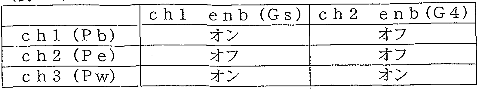


Claims
Priority Applications (5)
| Application Number | Priority Date | Filing Date | Title |
|---|---|---|---|
| CNB2004800208061A CN100394486C (zh) | 2003-07-18 | 2004-07-16 | 光记录方法 |
| EP04747937A EP1647976B1 (en) | 2003-07-18 | 2004-07-16 | Optical recording method |
| KR1020067000967A KR100889715B1 (ko) | 2003-07-18 | 2004-07-16 | 광기록 방법 |
| DE602004030576T DE602004030576D1 (de) | 2003-07-18 | 2004-07-16 | Optisches aufzeichnungsverfahren |
| US11/251,941 US7277376B2 (en) | 2003-07-18 | 2005-10-18 | Optical recording method |
Applications Claiming Priority (4)
| Application Number | Priority Date | Filing Date | Title |
|---|---|---|---|
| JP2003-199522 | 2003-07-18 | ||
| JP2003199522 | 2003-07-18 | ||
| JP2003334342 | 2003-09-25 | ||
| JP2003-334342 | 2003-09-25 |
Related Child Applications (1)
| Application Number | Title | Priority Date | Filing Date |
|---|---|---|---|
| US11/251,941 Continuation US7277376B2 (en) | 2003-07-18 | 2005-10-18 | Optical recording method |
Publications (1)
| Publication Number | Publication Date |
|---|---|
| WO2005013267A1 true WO2005013267A1 (ja) | 2005-02-10 |
Family
ID=34117887
Family Applications (1)
| Application Number | Title | Priority Date | Filing Date |
|---|---|---|---|
| PCT/JP2004/010574 WO2005013267A1 (ja) | 2003-07-18 | 2004-07-16 | 光記録方法 |
Country Status (8)
| Country | Link |
|---|---|
| US (1) | US7277376B2 (ja) |
| EP (1) | EP1647976B1 (ja) |
| JP (1) | JP4397751B2 (ja) |
| KR (1) | KR100889715B1 (ja) |
| CN (2) | CN100394486C (ja) |
| DE (1) | DE602004030576D1 (ja) |
| TW (1) | TWI265495B (ja) |
| WO (1) | WO2005013267A1 (ja) |
Cited By (1)
| Publication number | Priority date | Publication date | Assignee | Title |
|---|---|---|---|---|
| EP1929470A1 (en) * | 2005-08-31 | 2008-06-11 | Ricoh Company, Ltd. | Phase-change optical information recording medium and method for recording and recording apparatus using the same |
Families Citing this family (24)
| Publication number | Priority date | Publication date | Assignee | Title |
|---|---|---|---|---|
| DE60309232T2 (de) | 2002-03-05 | 2007-09-06 | Mitsubishi Kagaku Media Co. Ltd. | Phasenwechselaufzeichnungsmaterial für ein Informationsaufzeichnungsmedium und ein Informationsaufzeichnungsmedium dieses verwendend |
| US7106680B2 (en) * | 2002-05-10 | 2006-09-12 | Ricoh Company, Ltd. | Device and method for recording data to optical disk using multi-pulse to enhance power pulse |
| KR100474366B1 (ko) * | 2002-06-07 | 2005-03-10 | 엘지.필립스 디스플레이 주식회사 | 도밍 개선을 위한 음극선관 섀도우마스크 |
| JP4397751B2 (ja) | 2003-07-18 | 2010-01-13 | 三菱化学メディア株式会社 | 光記録方法及び光記録装置 |
| EP1675107A4 (en) | 2003-10-17 | 2009-02-18 | Mitsubishi Kagaku Media Co Ltd | OPTICAL RECORDING METHOD |
| KR20090091688A (ko) | 2006-12-28 | 2009-08-28 | 파나소닉 주식회사 | 정보 기록 매체 평가 방법, 정보 기록 매체, 정보 기록 매체의 제조 방법, 신호 처리 방법, 액세스 제어 장치 |
| US7924523B2 (en) * | 2007-12-21 | 2011-04-12 | Lsi Corporation | Frequency domain approach for efficient computation of fixed-point equalization targets |
| US8175201B2 (en) | 2007-12-21 | 2012-05-08 | Lsi Corporation | Systems and methods for adaptive equalization in recording channels |
| US7924518B2 (en) * | 2008-08-27 | 2011-04-12 | Lsi Corporation | Systems and methods for adaptive write pre-compensation |
| US9281908B2 (en) * | 2008-10-08 | 2016-03-08 | Avago Technologies General Ip (Singapore) Pte. Ltd. | Systems and methods for memory efficient signal and noise estimation |
| US7948702B2 (en) * | 2008-12-18 | 2011-05-24 | Lsi Corporation | Systems and methods for controlling data equalization |
| US7929240B2 (en) | 2008-12-18 | 2011-04-19 | Lsi Corporation | Systems and methods for adaptive MRA compensation |
| US7965467B2 (en) * | 2008-12-18 | 2011-06-21 | Lsi Corporation | Systems and methods for generating equalization data |
| US8154815B2 (en) | 2008-12-18 | 2012-04-10 | Lsi Corporation | Systems and methods for generating equalization data using shift register architecture |
| US7974030B2 (en) | 2008-12-23 | 2011-07-05 | Lsi Corporation | Systems and methods for dibit correction |
| US7948699B2 (en) * | 2009-01-02 | 2011-05-24 | Lsi Corporation | Systems and methods for equalizer optimization in a storage access retry |
| US7957251B2 (en) | 2009-02-16 | 2011-06-07 | Agere Systems Inc. | Systems and methods for reduced latency loop recovery |
| US7969337B2 (en) * | 2009-07-27 | 2011-06-28 | Lsi Corporation | Systems and methods for two tier sampling correction in a data processing circuit |
| US8139305B2 (en) * | 2009-09-14 | 2012-03-20 | Lsi Corporation | Systems and methods for timing and gain acquisition |
| US8854752B2 (en) | 2011-05-03 | 2014-10-07 | Lsi Corporation | Systems and methods for track width determination |
| US8762440B2 (en) | 2011-07-11 | 2014-06-24 | Lsi Corporation | Systems and methods for area efficient noise predictive filter calibration |
| US9112538B2 (en) | 2013-03-13 | 2015-08-18 | Avago Technologies General Ip (Singapore) Pte. Ltd. | Systems and methods for loop feedback |
| US8848776B1 (en) | 2013-03-25 | 2014-09-30 | Lsi Corporation | Systems and methods for multi-dimensional signal equalization |
| US8929010B1 (en) | 2013-08-21 | 2015-01-06 | Lsi Corporation | Systems and methods for loop pulse estimation |
Citations (3)
| Publication number | Priority date | Publication date | Assignee | Title |
|---|---|---|---|---|
| JP2002334433A (ja) * | 2001-05-02 | 2002-11-22 | Ricoh Co Ltd | 情報記録方法、情報記録装置及び情報処理装置 |
| JP2003331422A (ja) * | 2002-05-10 | 2003-11-21 | Ricoh Co Ltd | 記録ストラテジ生成方法及び光情報記録媒体 |
| JP2003331423A (ja) * | 2002-05-10 | 2003-11-21 | Ricoh Co Ltd | 情報記録方法及び情報記録装置 |
Family Cites Families (40)
| Publication number | Priority date | Publication date | Assignee | Title |
|---|---|---|---|---|
| JP2719130B2 (ja) | 1986-05-02 | 1998-02-25 | 株式会社日立製作所 | 情報の記録・再生および書き換え方法とその装置 |
| EP0243976B1 (en) * | 1986-05-02 | 1996-09-04 | Hitachi, Ltd. | Method for recording, reproducing and erasing information and thin film for recording information |
| JP2702923B2 (ja) | 1987-04-24 | 1998-01-26 | 株式会社日立製作所 | 情報の記録方法及び情報記録装置 |
| US5257256A (en) * | 1987-04-24 | 1993-10-26 | Hitachi, Ltd. | Recording waveform for mark-length modulation optical recording |
| JPH0810490B2 (ja) | 1989-03-20 | 1996-01-31 | 富士通株式会社 | 光ディスク情報書込制御方法およびその装置 |
| US5412626A (en) * | 1992-03-23 | 1995-05-02 | Matsushita Electric Industrial Co., Ltd. | Method of recording optical information with selective correction in pulse waveform and a recording system therefor |
| JP3266971B2 (ja) | 1992-03-23 | 2002-03-18 | 松下電器産業株式会社 | 光学情報の記録方法 |
| JP3255204B2 (ja) | 1993-07-22 | 2002-02-12 | 株式会社リコー | 光情報記録方法 |
| JPH0737251A (ja) | 1993-07-22 | 1995-02-07 | Ricoh Co Ltd | 光情報記録方法 |
| US5530688A (en) * | 1994-10-31 | 1996-06-25 | International Business Machines Corporation | Optical disk recording device using two modulated laser beams for recording information data |
| DE19612823C2 (de) * | 1995-03-31 | 2001-03-01 | Mitsubishi Chem Corp | Optisches Aufzeichnungsverfahren |
| JP3171103B2 (ja) | 1995-03-31 | 2001-05-28 | 三菱化学株式会社 | 光記録方法および光記録媒体 |
| JP3138610B2 (ja) | 1995-04-13 | 2001-02-26 | 株式会社リコー | 相変化型光ディスク用記録方法 |
| US5732062A (en) * | 1995-10-16 | 1998-03-24 | Ricoh Company, Ltd. | Information recording apparatus, method and computer program product |
| JP3022770B2 (ja) | 1996-04-16 | 2000-03-21 | 三菱化学株式会社 | 光記録方法、装置及び光記録媒体 |
| US6143468A (en) * | 1996-10-04 | 2000-11-07 | Mitsubishi Chemical Corporation | Optical information recording medium and optical recording method |
| JP3203618B2 (ja) * | 1997-05-19 | 2001-08-27 | ヤマハ株式会社 | 光ディスク記録担体 |
| JP3323782B2 (ja) | 1997-09-09 | 2002-09-09 | 株式会社日立製作所 | 情報の記録方法 |
| JPH11175976A (ja) * | 1997-12-09 | 1999-07-02 | Hitachi Ltd | 情報記録装置 |
| AU5647299A (en) * | 1998-09-09 | 2000-03-27 | Mitsubishi Chemical Corporation | Optical information recording medium and optical recording method |
| JP2001229537A (ja) | 1999-05-19 | 2001-08-24 | Mitsubishi Chemicals Corp | 書換え型光記録媒体及びその記録方法並びに光ディスク記録再生装置 |
| EP1662493B1 (en) * | 1999-05-19 | 2010-07-14 | Mitsubishi Kagaku Media Co., Ltd. | Recording at constant angular velocity |
| DE60037146T2 (de) * | 1999-05-19 | 2008-03-06 | Mitsubishi Kagaku Media Co. Ltd. | Optisches Aufzeichnungsverfahren und Medium |
| KR100322601B1 (ko) * | 1999-06-18 | 2002-03-18 | 윤종용 | 광디스크 기록 방법, 광디스크 기록 장치의 제어 방법 및 이에 적합한 광디스크 기록 장치 |
| EP1467352B1 (en) * | 2000-09-28 | 2008-01-09 | Ricoh Company, Ltd. | Phase change optical information recording medium and method for manufacturing same |
| KR100399998B1 (ko) * | 2001-01-09 | 2003-09-29 | 삼성전자주식회사 | 틸트 보상 방법 및 그 장치 |
| DE60235972D1 (de) * | 2001-03-06 | 2010-05-27 | Mitsubishi Kagaku Media Co Ltd | Optisches informationsaufzeichnungsmaterial und aufzeichnungs-/erlöschungsverfahren |
| US20020160305A1 (en) * | 2001-03-08 | 2002-10-31 | Mitsubishi Chemical Corporation | Optical recording medium, method of writing and erasing information using the same, and process of producing the same |
| EP1249834B1 (en) * | 2001-04-12 | 2012-09-12 | Ricoh Company, Ltd. | Information recording with effective pulse control scheme |
| US7864645B2 (en) * | 2001-04-26 | 2011-01-04 | Koninklijke Philips Electronics N.V. | Method and device for recording marks in an information layer of an optical record carrier |
| JP2003030833A (ja) * | 2001-07-13 | 2003-01-31 | Matsushita Electric Ind Co Ltd | 光記録媒体、光記録媒体の記録方法及び光記録媒体の記録装置 |
| JP2003030836A (ja) * | 2001-07-16 | 2003-01-31 | Hitachi Maxell Ltd | 情報の記録方法、情報記録媒体及び情報記録装置 |
| WO2003069602A1 (en) * | 2002-02-13 | 2003-08-21 | Mitsubishi Chemical Corporation | Rewritable optical recording medium and optical recording method |
| DE60309232T2 (de) * | 2002-03-05 | 2007-09-06 | Mitsubishi Kagaku Media Co. Ltd. | Phasenwechselaufzeichnungsmaterial für ein Informationsaufzeichnungsmedium und ein Informationsaufzeichnungsmedium dieses verwendend |
| US7106680B2 (en) * | 2002-05-10 | 2006-09-12 | Ricoh Company, Ltd. | Device and method for recording data to optical disk using multi-pulse to enhance power pulse |
| CN1662966A (zh) * | 2002-05-17 | 2005-08-31 | Tdk株式会社 | 用于在光记录介质中记录数据的方法和装置,及光记录介质 |
| EP1699044B1 (en) * | 2002-10-10 | 2007-10-24 | Matsushita Electric Industrial Co., Ltd. | Optical data recording method and device |
| JP3977740B2 (ja) | 2002-12-27 | 2007-09-19 | 株式会社リコー | 相変化型光記録媒体とその記録方法 |
| JP4231871B2 (ja) | 2003-02-28 | 2009-03-04 | パイオニア株式会社 | 情報記録装置及び情報記録方法 |
| JP4397751B2 (ja) | 2003-07-18 | 2010-01-13 | 三菱化学メディア株式会社 | 光記録方法及び光記録装置 |
-
2004
- 2004-07-16 JP JP2004209748A patent/JP4397751B2/ja not_active Expired - Fee Related
- 2004-07-16 CN CNB2004800208061A patent/CN100394486C/zh not_active Expired - Fee Related
- 2004-07-16 DE DE602004030576T patent/DE602004030576D1/de active Active
- 2004-07-16 CN CN2008100953327A patent/CN101261845B/zh not_active Expired - Fee Related
- 2004-07-16 WO PCT/JP2004/010574 patent/WO2005013267A1/ja active Application Filing
- 2004-07-16 EP EP04747937A patent/EP1647976B1/en not_active Expired - Fee Related
- 2004-07-16 TW TW093121389A patent/TWI265495B/zh not_active IP Right Cessation
- 2004-07-16 KR KR1020067000967A patent/KR100889715B1/ko active IP Right Grant
-
2005
- 2005-10-18 US US11/251,941 patent/US7277376B2/en active Active
Patent Citations (3)
| Publication number | Priority date | Publication date | Assignee | Title |
|---|---|---|---|---|
| JP2002334433A (ja) * | 2001-05-02 | 2002-11-22 | Ricoh Co Ltd | 情報記録方法、情報記録装置及び情報処理装置 |
| JP2003331422A (ja) * | 2002-05-10 | 2003-11-21 | Ricoh Co Ltd | 記録ストラテジ生成方法及び光情報記録媒体 |
| JP2003331423A (ja) * | 2002-05-10 | 2003-11-21 | Ricoh Co Ltd | 情報記録方法及び情報記録装置 |
Cited By (3)
| Publication number | Priority date | Publication date | Assignee | Title |
|---|---|---|---|---|
| EP1929470A1 (en) * | 2005-08-31 | 2008-06-11 | Ricoh Company, Ltd. | Phase-change optical information recording medium and method for recording and recording apparatus using the same |
| EP1929470A4 (en) * | 2005-08-31 | 2009-03-18 | Ricoh Kk | PHASE TRANSITION OPTICAL DATA RECORDING MEDIUM AND RECORDING METHOD AND DEVICE USING THE SAME |
| US7916603B2 (en) | 2005-08-31 | 2011-03-29 | Ricoh Company, Ltd. | Phase-change optical information recording medium and method for recording and recording apparatus using the same |
Also Published As
| Publication number | Publication date |
|---|---|
| CN100394486C (zh) | 2008-06-11 |
| KR100889715B1 (ko) | 2009-03-23 |
| CN101261845A (zh) | 2008-09-10 |
| CN101261845B (zh) | 2010-07-21 |
| EP1647976A1 (en) | 2006-04-19 |
| JP4397751B2 (ja) | 2010-01-13 |
| KR20060035758A (ko) | 2006-04-26 |
| DE602004030576D1 (de) | 2011-01-27 |
| TWI265495B (en) | 2006-11-01 |
| US7277376B2 (en) | 2007-10-02 |
| CN1826640A (zh) | 2006-08-30 |
| EP1647976A4 (en) | 2008-08-06 |
| JP2005122874A (ja) | 2005-05-12 |
| EP1647976B1 (en) | 2010-12-15 |
| US20060062125A1 (en) | 2006-03-23 |
| TW200515393A (en) | 2005-05-01 |
Similar Documents
| Publication | Publication Date | Title |
|---|---|---|
| US7277376B2 (en) | Optical recording method | |
| JP4521054B2 (ja) | 書き換え型光記録媒体 | |
| JP3899779B2 (ja) | 光記録方法 | |
| EP1434206B1 (en) | Phase change type optical recording medium and recording method therefor | |
| JP2006044215A (ja) | 光記録媒体及びその製造方法、スパッタリングターゲット、並びに光記録媒体の使用方法及び光記録装置 | |
| US7602675B2 (en) | Optical recording method | |
| JP2008097799A (ja) | 情報記録方法、情報記録媒体、及び情報記録装置 | |
| JP4405739B2 (ja) | 書換え型光記録媒体の光記録方法 | |
| JP4410081B2 (ja) | 光記録方法 | |
| JP3903811B2 (ja) | 光学的情報記録用媒体及び記録消去方法 | |
| JP3881215B2 (ja) | 光情報記録方法 | |
| JP2004022007A (ja) | 光記録方法及び光情報記録媒体 | |
| JP2005093027A (ja) | 光情報記録媒体及び記録方法 | |
| JP2002245630A (ja) | 情報記録媒体、情報記録方法及び情報記録装置 | |
| JP2007257809A (ja) | 光記録媒体及び光記録方法 | |
| JP2009043327A (ja) | 光情報記録媒体、光情報記録媒体への情報記録方法及び情報記録装置 |
Legal Events
| Date | Code | Title | Description |
|---|---|---|---|
| WWE | Wipo information: entry into national phase |
Ref document number: 200480020806.1 Country of ref document: CN |
|
| AK | Designated states |
Kind code of ref document: A1 Designated state(s): AE AG AL AM AT AU AZ BA BB BG BR BW BY BZ CA CH CN CO CR CU CZ DE DK DM DZ EC EE EG ES FI GB GD GE GH GM HR HU ID IL IN IS KE KG KP KR KZ LC LK LR LS LT LU LV MA MD MG MK MN MW MX MZ NA NI NO NZ OM PG PH PL PT RO RU SC SD SE SG SK SL SY TJ TM TN TR TT TZ UA UG US UZ VC VN YU ZA ZM ZW |
|
| AL | Designated countries for regional patents |
Kind code of ref document: A1 Designated state(s): BW GH GM KE LS MW MZ NA SD SL SZ TZ UG ZM ZW AM AZ BY KG KZ MD RU TJ TM AT BE BG CH CY CZ DE DK EE ES FI FR GB GR HU IE IT LU MC NL PL PT RO SE SI SK TR BF BJ CF CG CI CM GA GN GQ GW ML MR NE SN TD TG |
|
| 121 | Ep: the epo has been informed by wipo that ep was designated in this application | ||
| WWE | Wipo information: entry into national phase |
Ref document number: 2004747937 Country of ref document: EP |
|
| WWE | Wipo information: entry into national phase |
Ref document number: 11251941 Country of ref document: US |
|
| WWE | Wipo information: entry into national phase |
Ref document number: 1020067000967 Country of ref document: KR |
|
| WWP | Wipo information: published in national office |
Ref document number: 11251941 Country of ref document: US |
|
| WWP | Wipo information: published in national office |
Ref document number: 2004747937 Country of ref document: EP |