WO2003070592A1 - Contenant a couvercle ajuste - Google Patents
Contenant a couvercle ajuste Download PDFInfo
- Publication number
- WO2003070592A1 WO2003070592A1 PCT/JP2003/001857 JP0301857W WO03070592A1 WO 2003070592 A1 WO2003070592 A1 WO 2003070592A1 JP 0301857 W JP0301857 W JP 0301857W WO 03070592 A1 WO03070592 A1 WO 03070592A1
- Authority
- WO
- WIPO (PCT)
- Prior art keywords
- biodegradable
- film
- container
- molding
- sealed container
- Prior art date
Links
Classifications
-
- B—PERFORMING OPERATIONS; TRANSPORTING
- B65—CONVEYING; PACKING; STORING; HANDLING THIN OR FILAMENTARY MATERIAL
- B65D—CONTAINERS FOR STORAGE OR TRANSPORT OF ARTICLES OR MATERIALS, e.g. BAGS, BARRELS, BOTTLES, BOXES, CANS, CARTONS, CRATES, DRUMS, JARS, TANKS, HOPPERS, FORWARDING CONTAINERS; ACCESSORIES, CLOSURES, OR FITTINGS THEREFOR; PACKAGING ELEMENTS; PACKAGES
- B65D65/00—Wrappers or flexible covers; Packaging materials of special type or form
- B65D65/38—Packaging materials of special type or form
- B65D65/46—Applications of disintegrable, dissolvable or edible materials
-
- B—PERFORMING OPERATIONS; TRANSPORTING
- B32—LAYERED PRODUCTS
- B32B—LAYERED PRODUCTS, i.e. PRODUCTS BUILT-UP OF STRATA OF FLAT OR NON-FLAT, e.g. CELLULAR OR HONEYCOMB, FORM
- B32B27/00—Layered products comprising a layer of synthetic resin
- B32B27/06—Layered products comprising a layer of synthetic resin as the main or only constituent of a layer, which is next to another layer of the same or of a different material
- B32B27/065—Layered products comprising a layer of synthetic resin as the main or only constituent of a layer, which is next to another layer of the same or of a different material of foam
-
- B—PERFORMING OPERATIONS; TRANSPORTING
- B32—LAYERED PRODUCTS
- B32B—LAYERED PRODUCTS, i.e. PRODUCTS BUILT-UP OF STRATA OF FLAT OR NON-FLAT, e.g. CELLULAR OR HONEYCOMB, FORM
- B32B5/00—Layered products characterised by the non- homogeneity or physical structure, i.e. comprising a fibrous, filamentary, particulate or foam layer; Layered products characterised by having a layer differing constitutionally or physically in different parts
- B32B5/18—Layered products characterised by the non- homogeneity or physical structure, i.e. comprising a fibrous, filamentary, particulate or foam layer; Layered products characterised by having a layer differing constitutionally or physically in different parts characterised by features of a layer of foamed material
-
- B—PERFORMING OPERATIONS; TRANSPORTING
- B32—LAYERED PRODUCTS
- B32B—LAYERED PRODUCTS, i.e. PRODUCTS BUILT-UP OF STRATA OF FLAT OR NON-FLAT, e.g. CELLULAR OR HONEYCOMB, FORM
- B32B7/00—Layered products characterised by the relation between layers; Layered products characterised by the relative orientation of features between layers, or by the relative values of a measurable parameter between layers, i.e. products comprising layers having different physical, chemical or physicochemical properties; Layered products characterised by the interconnection of layers
- B32B7/02—Physical, chemical or physicochemical properties
- B32B7/027—Thermal properties
-
- B—PERFORMING OPERATIONS; TRANSPORTING
- B32—LAYERED PRODUCTS
- B32B—LAYERED PRODUCTS, i.e. PRODUCTS BUILT-UP OF STRATA OF FLAT OR NON-FLAT, e.g. CELLULAR OR HONEYCOMB, FORM
- B32B9/00—Layered products comprising a layer of a particular substance not covered by groups B32B11/00 - B32B29/00
- B32B9/02—Layered products comprising a layer of a particular substance not covered by groups B32B11/00 - B32B29/00 comprising animal or vegetable substances, e.g. cork, bamboo, starch
-
- B—PERFORMING OPERATIONS; TRANSPORTING
- B65—CONVEYING; PACKING; STORING; HANDLING THIN OR FILAMENTARY MATERIAL
- B65D—CONTAINERS FOR STORAGE OR TRANSPORT OF ARTICLES OR MATERIALS, e.g. BAGS, BARRELS, BOTTLES, BOXES, CANS, CARTONS, CRATES, DRUMS, JARS, TANKS, HOPPERS, FORWARDING CONTAINERS; ACCESSORIES, CLOSURES, OR FITTINGS THEREFOR; PACKAGING ELEMENTS; PACKAGES
- B65D65/00—Wrappers or flexible covers; Packaging materials of special type or form
- B65D65/38—Packaging materials of special type or form
- B65D65/46—Applications of disintegrable, dissolvable or edible materials
- B65D65/466—Bio- or photodegradable packaging materials
-
- B—PERFORMING OPERATIONS; TRANSPORTING
- B65—CONVEYING; PACKING; STORING; HANDLING THIN OR FILAMENTARY MATERIAL
- B65D—CONTAINERS FOR STORAGE OR TRANSPORT OF ARTICLES OR MATERIALS, e.g. BAGS, BARRELS, BOTTLES, BOXES, CANS, CARTONS, CRATES, DRUMS, JARS, TANKS, HOPPERS, FORWARDING CONTAINERS; ACCESSORIES, CLOSURES, OR FITTINGS THEREFOR; PACKAGING ELEMENTS; PACKAGES
- B65D77/00—Packages formed by enclosing articles or materials in preformed containers, e.g. boxes, cartons, sacks or bags
- B65D77/10—Container closures formed after filling
- B65D77/20—Container closures formed after filling by applying separate lids or covers, i.e. flexible membrane or foil-like covers
- B65D77/2024—Container closures formed after filling by applying separate lids or covers, i.e. flexible membrane or foil-like covers the cover being welded or adhered to the container
-
- B—PERFORMING OPERATIONS; TRANSPORTING
- B65—CONVEYING; PACKING; STORING; HANDLING THIN OR FILAMENTARY MATERIAL
- B65D—CONTAINERS FOR STORAGE OR TRANSPORT OF ARTICLES OR MATERIALS, e.g. BAGS, BARRELS, BOTTLES, BOXES, CANS, CARTONS, CRATES, DRUMS, JARS, TANKS, HOPPERS, FORWARDING CONTAINERS; ACCESSORIES, CLOSURES, OR FITTINGS THEREFOR; PACKAGING ELEMENTS; PACKAGES
- B65D81/00—Containers, packaging elements, or packages, for contents presenting particular transport or storage problems, or adapted to be used for non-packaging purposes after removal of contents
- B65D81/34—Containers, packaging elements, or packages, for contents presenting particular transport or storage problems, or adapted to be used for non-packaging purposes after removal of contents for packaging foodstuffs or other articles intended to be cooked or heated within the package
-
- B—PERFORMING OPERATIONS; TRANSPORTING
- B32—LAYERED PRODUCTS
- B32B—LAYERED PRODUCTS, i.e. PRODUCTS BUILT-UP OF STRATA OF FLAT OR NON-FLAT, e.g. CELLULAR OR HONEYCOMB, FORM
- B32B2266/00—Composition of foam
- B32B2266/02—Organic
- B32B2266/0214—Materials belonging to B32B27/00
- B32B2266/0264—Polyester
-
- B—PERFORMING OPERATIONS; TRANSPORTING
- B32—LAYERED PRODUCTS
- B32B—LAYERED PRODUCTS, i.e. PRODUCTS BUILT-UP OF STRATA OF FLAT OR NON-FLAT, e.g. CELLULAR OR HONEYCOMB, FORM
- B32B2307/00—Properties of the layers or laminate
- B32B2307/30—Properties of the layers or laminate having particular thermal properties
- B32B2307/31—Heat sealable
-
- B—PERFORMING OPERATIONS; TRANSPORTING
- B32—LAYERED PRODUCTS
- B32B—LAYERED PRODUCTS, i.e. PRODUCTS BUILT-UP OF STRATA OF FLAT OR NON-FLAT, e.g. CELLULAR OR HONEYCOMB, FORM
- B32B2307/00—Properties of the layers or laminate
- B32B2307/50—Properties of the layers or laminate having particular mechanical properties
- B32B2307/514—Oriented
- B32B2307/518—Oriented bi-axially
-
- B—PERFORMING OPERATIONS; TRANSPORTING
- B32—LAYERED PRODUCTS
- B32B—LAYERED PRODUCTS, i.e. PRODUCTS BUILT-UP OF STRATA OF FLAT OR NON-FLAT, e.g. CELLULAR OR HONEYCOMB, FORM
- B32B2307/00—Properties of the layers or laminate
- B32B2307/70—Other properties
- B32B2307/716—Degradable
- B32B2307/7163—Biodegradable
-
- B—PERFORMING OPERATIONS; TRANSPORTING
- B32—LAYERED PRODUCTS
- B32B—LAYERED PRODUCTS, i.e. PRODUCTS BUILT-UP OF STRATA OF FLAT OR NON-FLAT, e.g. CELLULAR OR HONEYCOMB, FORM
- B32B2439/00—Containers; Receptacles
- B32B2439/40—Closed containers
-
- B—PERFORMING OPERATIONS; TRANSPORTING
- B32—LAYERED PRODUCTS
- B32B—LAYERED PRODUCTS, i.e. PRODUCTS BUILT-UP OF STRATA OF FLAT OR NON-FLAT, e.g. CELLULAR OR HONEYCOMB, FORM
- B32B2439/00—Containers; Receptacles
- B32B2439/70—Food packaging
-
- Y—GENERAL TAGGING OF NEW TECHNOLOGICAL DEVELOPMENTS; GENERAL TAGGING OF CROSS-SECTIONAL TECHNOLOGIES SPANNING OVER SEVERAL SECTIONS OF THE IPC; TECHNICAL SUBJECTS COVERED BY FORMER USPC CROSS-REFERENCE ART COLLECTIONS [XRACs] AND DIGESTS
- Y02—TECHNOLOGIES OR APPLICATIONS FOR MITIGATION OR ADAPTATION AGAINST CLIMATE CHANGE
- Y02A—TECHNOLOGIES FOR ADAPTATION TO CLIMATE CHANGE
- Y02A40/00—Adaptation technologies in agriculture, forestry, livestock or agroalimentary production
- Y02A40/90—Adaptation technologies in agriculture, forestry, livestock or agroalimentary production in food processing or handling, e.g. food conservation
-
- Y—GENERAL TAGGING OF NEW TECHNOLOGICAL DEVELOPMENTS; GENERAL TAGGING OF CROSS-SECTIONAL TECHNOLOGIES SPANNING OVER SEVERAL SECTIONS OF THE IPC; TECHNICAL SUBJECTS COVERED BY FORMER USPC CROSS-REFERENCE ART COLLECTIONS [XRACs] AND DIGESTS
- Y02—TECHNOLOGIES OR APPLICATIONS FOR MITIGATION OR ADAPTATION AGAINST CLIMATE CHANGE
- Y02W—CLIMATE CHANGE MITIGATION TECHNOLOGIES RELATED TO WASTEWATER TREATMENT OR WASTE MANAGEMENT
- Y02W90/00—Enabling technologies or technologies with a potential or indirect contribution to greenhouse gas [GHG] emissions mitigation
- Y02W90/10—Bio-packaging, e.g. packing containers made from renewable resources or bio-plastics
Definitions
- the present invention relates to a biodegradable container main body including starch as a main raw material, a biodegradable foamed molded product, and a covering film attached to the surface thereof;
- the present invention relates to a hermetically sealed container having a sealed lid, and particularly to a hermetically sealed container which can be suitably used as various kinds of disposable foamed molded products discarded after use, such as a food container. Background art
- plastic moldings and paper ⁇ pulp moldings are the mainstream disposable moldings that are discarded after use. This is because, although it depends on the use of the molded article, generally, the material of the disposable molded article is required to have a certain degree of durability and strength and also to be easily molded.
- any of the above-mentioned plastic molded article and paper pulp molded article has various problems as described below in order to be used as a disposable molded article.
- plastic moldings cause problems such as extremely high temperatures generated during the incineration process, which can damage the incinerator and produce by-products such as dioxins.
- landfilling of plastic moldings Two
- plastic moldings are not easily decomposed, they can also pollute the natural environment continuously and for a long time.
- paper and pulp molded products are superior to plastic molded products in this respect because they are easily incinerated and decomposed in the natural environment.
- the tree used as the raw material for pulp and paper has a long growth cycle, and the consumption of a large amount of paper and pulp greatly reduces forest resources. Decreasing forest resources not only severely damages the local environment, but also, on a large scale, significantly reduces the ability of forests to absorb carbon dioxide and increases global It will also spur warming.
- the thickness (wall thickness) of a molded product made of biodegradable plastic is large, it takes a very long time to completely decompose it, and the volume of the molded product in a practical range Cannot be increased.
- the molded product made of the biodegradable plastic is used as a disposable tableware or the like, it is the most environmentally friendly treatment method to form a composition together with food residue.
- the decomposition rate of the above-mentioned biodegradable plastic is much lower than that of food residues. It is difficult to combo.
- starch-protein etc. have good biodegradability, and can be easily degraded even if the volume is large. However, it is not difficult to secure resources, and it is almost always used as a foamed molded product.Therefore, there is an advantage that a molded product having both an appropriate thickness and heat insulation can be obtained, which is particularly attracting attention. . ⁇
- Examples of the biodegradation disposal technology using starch, protein, etc. include the following: (1) Japanese Patent Publication “Japanese Patent Application Laid-Open No. 5-320401” (Published date: January, 1993 3), 2 Japanese Patent Application Publication “Japanese Patent Application Laid-Open No. Hei 7-22411 (published on August 22, 1995)”, 3 Japanese Patent Application Publication Japanese Patent Application Publication No. 1 148 Publication ”(publication date: January 13, 1995), 4 B Patent Publication in the United States“ Japanese Patent Application Laid-Open Publication No. 2000-144 2783 Publication ”(publication date: Heisei 1 May 23, 2005), and Japanese Patent Publication No. JP-A-7-975455 (publication date: April 11, 1995).
- the molded product is formed using starch or various polysaccharides similar thereto as the main substance, and the surface of the molded product is improved in order to improve water resistance.
- a natural resin (dammar resin ⁇ ⁇ shellac resin, etc.) is applied to the surface to form a water-resistant coating.
- dammar resin / shell resin and the like must be dissolved in an organic solvent such as alcohols for coating. Therefore, when removing the organic solvent after the coating process, large-scale equipment is required to prevent the organic solvent from diffusing into the air and contaminating the atmosphere and the surrounding environment. Invite points.
- the aliphatic polyester is dissolved in the lipophilic hydrocarbon on the surface of a poorly water-resistant biodegradable material such as starch.
- a biodegradable coating agent is applied.
- the dipping method immersion coating method
- the dipping method is used as a specific coating method, so it is possible to form an appropriate water-resistant coating even on a molded article with a complicated shape.
- halogenated hydrocarbons are unfavorable to the human body and the environment.
- the halogenated hydrocarbons specifically mentioned in the technology (1) are fluorocarbons, so they are scattered to the atmosphere as much as possible. Don't let it. As a result, there is a problem that a large airtight chamber and a recovery device are required as the above-mentioned device.
- PIX is prepared as a coating liquid and then applied to the surface of a molded product.
- a water-resistant coating is sufficiently uniform over the entire surface of the molded product.
- a flat molded product such as a flat plate is relatively easy to apply, but a molded product composed mainly of starch as described above tends to have irregularities on its surface, hindering the formation of a uniform film.
- the molded product has a substantially circular cross section, such as a lip shape and a bowl shape, it is necessary to rotate the molded product and the application device, and the difficulty of application is further increased.
- the coating solution after application would flow down until it solidified and formed on the coating, resulting in uneven coating.
- the problem that liability is likely to occur also arises.
- the above-mentioned wax has a problem that it has poor heat resistance due to its relatively low melting point.
- the hydrophobic protein has relatively good heat resistance and does not require the use of an organic solvent.
- an aqueous solvent is often used, the molded product absorbs moisture during the coating process and softens.
- a technique of laminating a water-resistant coating instead of applying the water-resistant coating on the surface of the molded product has been conventionally proposed.
- a container obtained by a pulp mold method is covered with a non-water-permeable or non-absorbable protective layer.
- This technology has the advantage that the conventional plastic coating technology for paper containers can be applied almost as it is, but since the main component of the pulp mold is fiber, the biodegradation rate is slow and food residues and the like are low. There are problems that they cannot be discarded together, that it is difficult to make the container thicker, that they are not suitable for deep drawing and that they are not suitable for producing a wide variety of molded products.
- a biodegradable plastic thin film is coated on the surface of a biodegradable container made of natural polybranches, proteins, or those chemically modified to the extent that they can be biodegraded. And manufactures biodegradable containers.
- biodegradable plastics are used as a thin water-resistant coating, while the container body is molded from natural polysaccharides, proteins, etc. into a sufficiently thick container, so that sufficient water resistance is obtained. It can also exhibit sufficient biodegradability while exhibiting its properties. Therefore, it is a particularly promising technology for disposal by biodegradation using starch protein.
- the technique (1) has a configuration in which the biodegradable container body is simply covered with a biodegradable plastic thin film, and hardly mentions a specific configuration of the biodegradable container.
- the biodegradable container body is mainly composed of a polysaccharide / protein
- its strength is a problem, but the technique in (1) does not describe the strength at all.
- the technique in (1) does not describe the strength at all.
- there is no description about how to specifically cover the biodegradable plastic thin film for example, whether to previously form and attach a force-coated film formed by a coating method.
- the state of coating of the biodegradable plastic body on the biodegradable container body is not specified at all.
- the biodegradable plastic thin film is coated to improve the water resistance of the biodegradable container body mainly composed of polysaccharide / protein.
- the one-way container must be stable and durable, and the biodegradable plastic thin film will easily peel off from the biodegradable container body. They are not durable. Therefore, the covering state of the container body is an important condition, but this technique does not consider this point at all.
- biodegradable plastics have a low biodegradation rate, making it difficult to use them as thick molded products.However, the biodegradation rate is limited only by the thickness of the molded product. Without depending on the total amount contained in the molding .
- the technology described in (1) only describes that foaming the biodegradable container body improves the biodegradability.
- the relationship between the degree of foaming and biodegradability, and the relationship between biodegradable plastic and biodegradable No mention is made of the balance of biodegradation with the body of the degradable container, and therefore the biodegradation of the entire container cannot be satisfactorily advanced.
- the technique (1) is presumed to correspond to one of the methods for producing a biodegradable container disclosed in the above (2), but in this technique, a thermoplastic is dissolved in a solvent, After applying it to the surface of the biodegradable container body and drying it to evaporate the solvent, another coating thin film made of thermoplastic plastic is laminated and thermocompression bonded. That is, it discloses that a thermoplastic plastic is used as an adhesive to stably adhere a coating thin film (corresponding to a biodegradable plastic thin film).
- thermoplastic plastic dissolved in a solvent causes problems such as the necessity of a device for preventing the diffusion of the solvent.
- a black hole form is used as a solvent, which should not be scattered in the atmosphere as much as possible.
- a sheet is first formed from polysaccharides and proteins, and then the sheet is press-molded with a mold to obtain a biodegradable container body.
- a deep drawn container such as a cup or a molded product such as a food tray with partitions is not uniform in thickness. This leads to a problem that a difficult product cannot be formed.
- a container for storing food a container body having a space for accommodating food therein and having an opening for taking in and out the food, and sealing the opening of the container body
- a sealed container is used, which comprises a plastic film whose main component is plastic for sealing, and the lid film is heat-sealed to the periphery of the opening of the container body.
- a container for cup noodles a sealed container in which a lid film made of aluminum on a plastic film is heat-sealed to the periphery of the opening of the bowl-shaped container body made of styrene foam is used. ing.
- the containers currently used as cup noodle containers are not biodegradable.
- the present invention has been made in view of the above problems, and has as its object the purpose of achieving sufficient strength, at least sufficient water resistance, and exhibiting extremely good biodegradability.
- the present invention provides sufficient strength to maintain the quality of the contents at the time of distribution and storage, and to prevent breakage, light-shielding properties, odor-blocking properties (fragrance-retaining properties, odor-blocking properties), and gas barrier properties. (Such as water vapor barrier property and oxygen barrier property) as a storage container, and also as a cooking container with heat resistance, water resistance, and heat retention.
- the sealed container of the present invention has a biodegradable container having a space for accommodating the contents therein and having an opening for taking in and out the contents.
- the container main body includes a biodegradable foam molded article molded into a predetermined shape. And a covering film attached to the surface thereof.
- the above-mentioned biodegradable foamed molded product comprises starch or a derivative thereof as a main component, and is formed into a slurry or a dough by mixing with water.
- the coating film is formed by steam foaming the raw material for use, and the coating film has a biodegradable plastic as a main component and has at least hydrophobicity, and the lid is an opening of the container body. Lap of It is characterized by being heat-sealed to the part.
- the biodegradable foamed molded product is prepared by preparing a slurry-shaped or dough-shaped molding raw material using starch as a main component, and performing steam foam molding using the raw material.
- the molded foam obtained has a certain moisture content, and can exhibit superior strength compared to conventional starch molded products.
- a biodegradable coating film is applied to this foamed molded product. For example, by thermocompression bonding using the same mold as that used to mold the foamed molded product, or by attaching it at the same time as foam molding, it is possible to securely fit the shape of the foamed molded product. And it becomes possible to coat easily. .
- the molded article constituting the container body is a foam (foamed molded article)
- the heat insulating property is excellent.
- the heat escapes to the outside and cools down, or the outer surface of the container body becomes too hot and it becomes difficult to hold by hand. Can be avoided.
- the molded product constituting the container body is a foam (foamed molded product)
- a certain light-shielding property can be obtained. As a result, for example, when the food is stored as a container in the space inside the container body, it is possible to prevent the deterioration of the quality of the food due to light.
- the above-mentioned coating film is mainly composed of biodegradable plastic having a property close to that of a general plastic, and has at least a hydrophobic property. Water resistance can be imparted to a foamed molded product containing starch as a main component. In addition, various functions such as gas barrier properties can be provided externally by appropriately selecting the type of the biodegradable plastic.
- the lid is preferably a film containing a biodegradable plastic as a main component.
- both the container body and the lid are biodegradable, After opening the sealed container and taking out the contents, it is possible to perform the biodegradation treatment without separating the container from the container main body or by combining the lid separated from the container main body with the container main body. . Therefore, it is not necessary to separate the sharks, and the trouble of disposal processing can be saved.
- a more environmentally friendly sealed container can be provided because the lid is biodegradable.
- the lid is made of a film mainly composed of plastic, it is possible to provide the lid with moisture permeability and gas barrier properties. Further, since the lid is made of a film and is easily bent, it is easy to peel off the lid when opening.
- Both the upper IB-coated film and the lid preferably have a melting point of at least 130 ° C of the biodegradable plastic as the main component.
- the body of the yogyu is made of a foamed molded container (biodegradable foamed molded product) mainly composed of starch having a very excellent heat resistance, and a heat-resistant film (coated film).
- the lid is also made of a heat-resistant material, and both the container body and the lid have good heat resistance. Therefore, even when contents with a high temperature of about 100 ° C are placed, the container body and lid have sufficient strength.
- Heat resistance and water resistance ⁇ Provide sealed containers that can maintain moisture resistance it can. Therefore, the sealed container having the above structure is suitable for applications in which hot water is poured, such as a cup noodle container.
- a modified polyester is preferable.
- the sealed container of the present invention is suitable as a food container. That is, in the hermetically sealed container of the present invention, it is preferable that food is enclosed as a contained material in the space inside the container main body. This allows the space inside the sealed container to be Even if there is food residue, the biodegradation treatment can be performed entirely, including the food residue.
- FIG. 1 is a schematic cross-sectional view showing the shape of a bowl-type sealed container as an example of a sealed container according to an embodiment of the present invention.
- FIG. 2 is a schematic cross-sectional view showing the shape of a dish-shaped sealed container as an example of the sealed container according to one embodiment of the present invention.
- FIG. 3 is a schematic cross-sectional view showing the shape of a cup-type sealed container as an example of the sealed container according to one embodiment of the present invention.
- FIGS. 4 (a) and 4 (b) are schematic cross-sectional views showing the shape of a bowl-type container as an example of a biodegradable container main body according to an embodiment of the present invention.
- FIGS. 5 (a) and 5 (b) are schematic sectional views showing the shape of a dish-shaped container as another example of the biodegradable container main body according to one embodiment of the present invention.
- 6 (a) and FIG. 6 (b) are schematic sectional views showing the shape of a cup-shaped container as yet another example of the biodegradable container body according to one embodiment of the present invention, and
- FIG. It is a schematic plan view. .
- FIG. 7 is a graph showing the composition of the raw material for molding used in the present invention.
- the graph (I) based on the whole raw material for molding and the graph based on the total solid content are shown in FIG.
- a rough relationship between the rough (II) and the graph (III) showing the total amount of the raw material components and water is also shown.
- FIGS. 8 (a) and 8 (b) are schematic cross-sectional views showing the configuration of a molding die for molding the foamed molded product serving as the body of the bowl shown in FIGS. 4 (a) and 4 (b). It is.
- FIGS. 9 (a) and 9 (b) are schematic cross-sectional views showing the configuration of a molding die for molding the foamed molded product serving as the main body of the dish-shaped container shown in FIGS. 5 (a) and 5 (b). It is.
- FIGS. 10 (a) and 10 (b) show the configuration of a molding die for molding the foamed molded product serving as the body of the cup-shaped container shown in FIGS. 6 (a) and 6 (b).
- FIG. 2 is a schematic cross-sectional view showing one example.
- Fig. 11 (a) and Fig. 11 (b) show the configuration of a molding die for molding the foam molded product that is the body of the cup-shaped container shown in Figs. 6 (a) and 6 (b). It is a schematic sectional drawing which shows the other example of.
- FIG. 12 is a schematic explanatory view showing an example of a configuration in which electrodes are provided for internal heating in the mold shown in FIGS. 8 (a) and 8 (b).
- Fig. 13 (a.) Is a schematic cross-sectional view showing the shape of a foamed molded product formed by the mold shown in Figs. 8 (a) and 8 (b), and Fig. 13 (b) Fig. 9 (a) and Fig. 9 (b) are schematic cross-sectional views showing the shape of the foamed molded article formed by the mold shown in Fig. 9 (b).
- Figs. 13 (c) are Figs. 10 (a) and 10 FIG. 2 (b) or a schematic cross-sectional view showing the shape of a foam molded article formed by the mold shown in FIGS. 11 (a) and 11 (b).
- Fig. 14 is a diagram for explaining the attaching process of attaching the coated film to the surface of the biodegradable foamed molded product shown in Fig. 13 (a) using the post-applying method.
- FIG. 1 A first figure.
- Fig. 15 (a) is a schematic explanatory view showing the state of application of the coating film on the surface of the biodegradable container main body to which the coating film has been applied using the post-pasting method. (b) is a schematic explanatory view showing the state of attachment of the coating film on the surface of the biodegradable container body to which the coating film has been attached using the simultaneous attachment method.
- FIG. 16 is an explanatory diagram illustrating a case where the production method 1 is used in the simultaneous bonding method for producing the dish-shaped container shown in FIG. 5 (a).
- FIG. 17 is an explanatory diagram for explaining the case where the production method 2 is used in the simultaneous bonding method for producing the bowl type container shown in FIG. 4 (a).
- FIG. 18 is an explanatory diagram illustrating a case where the production method 3 is used in the simultaneous sticking method for producing the dish-shaped container shown in FIG. 5 (a).
- FIG. 19 is an explanatory diagram for explaining the case where the production method 4 is used in the simultaneous bonding method for producing the bowl type container shown in FIG. 4 (a).
- FIG. 20 (a) is a schematic plan view showing an example of a two-part division in which the coated film is cut off as a film piece when the cup-shaped container shown in FIG. 6 (a) is manufactured using the manufacturing method 5.
- FIG. 20 (b) is a schematic plan view showing an example of three divisions in a state where the covering film is cut out as a film piece.
- FIG. 21 is an explanatory diagram for explaining a case where the production method 5 is used in the simultaneous bonding method for producing the cup-shaped container shown in FIG. 6 (a).
- FIG. 22 is an explanatory diagram for explaining the case where the manufacturing method 6 is used in the simultaneous bonding method for manufacturing the cup-shaped container shown in FIG. 6 (a).
- FIG. 23 is an explanatory view illustrating a case where the production method 7 is used in the simultaneous bonding method for producing the cup-shaped container shown in FIG. 6 (a).
- Fig. 24 (a) is a schematic diagram showing the joining state of the lid and the bowl when the covering film is attached to the edge of the bowl in the bowl of the bowl shown in Fig. 1.
- FIG. 24 (b) is a schematic explanatory view showing a joint state between the lid and the bowl when the covering film is not attached to the edge of the bowl.
- the sealed container according to the present invention includes a biodegradable container main body (container main body) having a space for accommodating the contents therein, and having an opening for taking in and out the contents.
- a lid mainly composed of plastic for sealing the opening of the container main body, wherein the lid is heat-sealed to the periphery of the opening of the biodegradable container main body.
- the biodegradable container main body is a biodegradable molded product including a biodegradable foam molded product formed into a predetermined shape, and a covering film attached to a surface thereof.
- the coating film has a biodegradable plastic as a main component and has at least hydrophobicity.
- the biodegradable foamed molded product is obtained by subjecting a slurry or dough-shaped raw material obtained by mixing starch and a derivative thereof to water as a main component and steam-foaming the mixture. It is molded.
- the amount of the biodegradable plastic such as a coating film with respect to the biodegradable foamed molded product is regulated to a certain amount, or, in other words, the amount of the biodegradable foamed molded product is limited to Percentage of volume of air phase contained It is preferable that the coating film is coated on the surface of the biodegradable foamed article in a state of being substantially adhered.
- the adhesion state at this time is more preferably that the coating film is in direct contact, but may be through an adhesive layer.
- the above-mentioned biodegradable foamed molded product is abbreviated as “foamed molded product” as appropriate.
- the slurry state refers to a state in which at least water has been added to starch and has sufficient fluidity. Therefore, the starch does not need to be dissolved in water, as long as it is close to a suspension.
- the above-mentioned dough state is a state in which the fluidity is lower than the above-mentioned slurry state, and is in a state close to semi-solid.
- the biodegradable container body will be described. Specifically, as an example of the body of the biodegradable container, a bowl-shaped container (hereinafter referred to as a bowl-type container) is exemplified as shown in FIG. 4 (a). It has a container body 11a, which is the above-mentioned biodegradable foam molded article, and a covering film 12 which is directly and almost adhered so as to cover the surface thereof.
- the container is interposed between the container main body 11a and the coated film 12, and the coated pinhole 12 is provided. May be provided on the surface of the container body 11a. As will be described later, the surface of the container body 11a does not need to be entirely covered with the covering film 12, but may be partially covered.
- a dish-shaped container (dish-shaped container) is given.
- the dish-shaped container 10b is also a container.
- the configuration consists of the main body 1 1b and the covering film 12 or
- an adhesive layer 13 is provided between the container body 11 b and the coating film 12.
- a cup-shaped container (cup-shaped container) can be mentioned as shown in FIG. 6 (a).
- c is also composed of the container body 1 1 c and the coating film 12, or as shown in FIG. 6 (b), an adhesive is applied between the container body 1 1 c and the coating film 12. It has a configuration having a layer 13.
- the upper diagram is a longitudinal sectional view of the cup-shaped container 10c
- the lower diagram is a plan view corresponding to the upper diagram (the cup-shaped container).
- Figure 10c is a bird's-eye view from above).
- the above-mentioned biodegradable foamed molded product which is the main body of the biodegradable container body (the above-mentioned container body 1 la.llb.llc), comprises starch or a derivative thereof as a main component and a slurry obtained by mixing water with this. It is formed by steam foaming from a raw or dough-shaped raw material for molding.
- the starch used as the main raw material of the raw material for molding is not particularly limited.
- starch that can be easily obtained from agricultural products produced worldwide as main cereals, such as potato, corn (corn), tapiochi, rice, wheat, and sweet potato, can be suitably used.
- the starch may be produced from a specific agricultural product, or may be a mixture of a plurality of agricultural products.
- the above-mentioned starch derivative refers to a starch modified within a range that does not inhibit biodegradability, and specifically includes, for example, pregelatinized starch, cross-linked starch, and modified starch. Further, a mixture of the unmodified starch and the derivative of the above starch may be used. it can. Therefore, in a broad sense, the starch in the present invention includes starch that has not been modified at all (starch in a narrow sense), derivatives of the above starch, and mixtures thereof. In the following description, unless otherwise specified, “starch” refers to starch in a broad sense.
- the starch content in the above-mentioned forming raw material is calculated by dividing the total amount of the main solid content of the forming raw material by 10 °° C.
- the content is preferably in the range of 50% by weight or more and 100% by weight or less.
- the entire raw material for molding including water is 100% by weight
- the main component of the biodegradable container body can be regarded as starch, and good biodegradability can be exhibited.
- the main solid content and the total amount thereof will be described later.
- the molding raw material may contain various additives in addition to the starch.
- the additive include a bulking agent, a strength adjuster, a plasticizer, an emulsifier, a stabilizer, a release agent, a homogeneity adjuster, a humectant, a soldering adjuster, and a conductivity.
- the additive include a regulator, a dielectric loss regulator, a swelling agent, and a coloring agent.
- additives have advantages in the production process, such as improving the production efficiency of the biodegradable container body and avoiding problems in the production process, and the quality of the biodegradable container body obtained. To improve the quality of biodegradable containers and reduce the cost of the main body. Some of the advantages are listed. These additives are not particularly limited as long as they do not significantly reduce the quality of the foamed molded product and the biodegradable container body.
- the extender is an additive that is added to the raw material for molding to increase the amount of the raw material for molding so as to reduce the use amount of starch, which is the main raw material, as much as possible to reduce the cost. For this reason, there is no particular limitation as long as it is cheaper than starch, but preferably, by-products involved in the processing and production of foods and the like that also serve as waste disposal can be suitably used.
- vegetables and fruits such as celery, carrot, tomato, citrus (citrus, lemon, grapefruit, etc.), lingo, grapes, berries, pineapple, sugar cane, and beetroot Manufacture of foods (food and drink) as raw materials ⁇ Juice grounds, pomace, and mixtures thereof produced during processing, etc .
- Processed foods made from grains such as tofu such as okara (3) Sake lees, burned lees, beer yeast cake, wine yeast cake, or a mixture thereof produced during the production of sake such as sake, shochu, and beer-pine.
- the strength adjuster is an additive that adjusts the strength of the foamed molded product and the biodegradable container body (particularly, improves the strength), and is not particularly limited.
- Mucous polysaccharides or mixtures thereof (15) chlorides, sulfates, organic acid salts, carbonates, hydroxides of metals such as calcium, sodium, potassium, luminium, magnesium and iron (16) Insoluble minerals such as quartz powder, diatomaceous earth, talc, and silicon, or mixtures thereof; (17) Cellulose, microcrystalline cellulose, and the like.
- the plasticizer is an additive that improves the flow characteristics of the raw material for molding and gives flexibility to the obtained foamed molded product and the biodegradable container body, and is not particularly limited. for example, listed above ⁇ agent (1) to various by-products (9); various compounds of cited as an intensity modifier (10) to (21) and (23) as well (2 4); (26) acetyl polybutyl citrate, or sugar alcohols such as glycerin, polyglycerin, propylene glycol, ethylene glycol, or a mixture thereof; These may be used alone or in combination of two or more.
- the emulsifier is an additive for sufficiently mixing the oil-based additive to form an oil-in-water type emulsion when the oil-based additive is added to the raw material for molding, and is particularly limited.
- specifically for example, (27) glyceric acid ester, poly (glycerinic acid ester), propylene glycol cornole fatty acid ester, sugar ester, sorbitan acid ester, lecithin, polysorbate And a mixture thereof.
- the stabilizer is an additive for stabilizing the state of the prepared molding raw material, and is not particularly limited. Specifically, for example, the above-mentioned starch as the main raw material is used. (Narrow sense; no modification) or derivatives thereof; (10) sugars mentioned in the above strength modifier; (11) sugar alcohols; (14) mucopolysaccharides; (17) vegetable fibers and derivatives thereof (paper (21) fatty acids, fatty acid salts, and fatty acid derivatives. These may be used alone or in combination of two or more.
- the above-mentioned release agent is an additive that is added to facilitate removal of the foamed molded product from the molding die and to make the surface of the foamed molded product as smooth as possible, and is not particularly limited. However, specifically, for example, (12) fats and oils; (13) waxes; (14) thickening polysaccharides; (21) fatty acids, fatty acid salts, fatty acid derivatives; No. These may be used alone or as a mixture of two or more.
- the homogeneity modifier is used for the homogeneity of the slurry or dough-like molding material, that is, the “texture” of the molding material (in this case, the solid that forms a slurry state or a dough state). Minute particles)
- An additive for achieving a uniform and smooth state and is not particularly limited. Specifically, for example, the above-mentioned starch as a main raw material (in a narrow sense, without modification) or a derivative thereof; The various by-products of (1) to (9) listed as the extender; the various compounds of (10) to (25) listed as the strength modifier; and the like. These may be used alone or in combination of two or more.
- the humectant is for allowing the foamed molded article to contain a certain amount of moisture, and has the same function as the plasticizer.
- the foamed product containing starch as a main component is in a state containing a certain amount of moisture (moisturizing condition)
- the brittleness (brittleness) of the alpha-modified starch is reduced, while its strength and flexibility are reduced. The effect of improving is obtained. Therefore, humectants also function as plasticizers and strength adjusters.
- the humectant is not particularly limited, but specifically, for example, the above-mentioned starch (unmodified in a narrow sense) or a derivative thereof as a main raw material; (1) to (9) various by-products; (10) saccharides listed as strength modifiers; (11) sugar alcohols; (12) fats and oils; (13) waxes; (14) ⁇ mucopolysaccharides; ( 5 ) metal salts; (17) vegetable fibers and derivatives thereof; (19) natural materials such as shells, bone meal, eggshells, leaves, and wood powder; and (22) food additives. These may be used alone or in combination of two or more.
- the above-mentioned handling adjuster functions as a slurry adjuster, and is an additive that improves the handleability of a slurry-like or dough-like molding material, and is not particularly limited.
- the above-mentioned plasticizer-emulsifier ⁇ All the materials and compounds mentioned as the stabilizer can be used. This These may be used alone or as a mixture of two or more.
- the above-mentioned conductivity adjuster is used to control the heat generation state when the foamed product is formed by internally heating as described later, particularly when the inside is heated by energized heating to perform heat molding. It is an additive for adjusting the dielectric constant of a raw material for molding, which is one of the clusters, and is not particularly limited. (13) wax; (14) viscous polysaccharides; (15) metal salts; (28) various water-soluble electrolytes such as salts, acids, alkalis, and alcohols; These may be used alone or as a mixture of two or more.
- the above-mentioned dielectric loss modifier is one of the factors for controlling the state of heat generation when molding a foamed molded product, particularly in the case of performing heat molding by internally generating heat by high-frequency dielectric heating. It is an additive for adjusting the dielectric loss of the steel, and is not particularly limited. Specifically, for example, (12) fats and oils; (13) wax; ) Metal salts; (16) Insoluble minerals; (17) Vegetable fibers and derivatives thereof; (28) Various water-soluble electrolytes mentioned in the above-mentioned dielectric constant modifier; (29) Zirconium salt, ammonium zirconium carbonate solution, etc. A zirconium salt-containing compound, or a mixture thereof; and the like. These may be used alone or as a mixture of two or more.
- the above-mentioned expansion agent is an additive for adjusting the degree of foaming of the raw material for molding, or for further promoting expansion, so as to obtain a foam molded product suitable for the shape and application, and is not particularly limited.
- organic leavening agents such as benzenesulfohydrazine compounds, azonitrile compounds, nitroso compounds, diacetamide compounds, and azocarboxylic acid compounds;
- the colorant is an additive that is added for the purpose of coloring the entire foamed molded product, and is not particularly limited.
- inorganic colorants such as titanium dioxide and carbon black
- Natural or synthetic organic dyes such as various colorants specified by the color index
- Colorants of natural materials such as caramel and cocoa powder; and the like. These may be used alone or as a mixture of two or more.
- titanium dioxide As an additive contained in the molding raw material, titanium dioxide has excellent light-shielding properties, exhibits a beautiful white color that enhances aesthetics during surface printing, and improves strength and gas barrier properties. It is preferred as an additive because it can be used.
- the amount of titanium dioxide used in the raw material for molding is preferably at least 0.2% by weight, more preferably at least 0.3% by weight. , And more preferably 4% by weight or more.
- the content of the extender (which may also be expressed as a bulking additive) is defined as the total solid content of the molding raw material. It is preferable that the content is not more than the starch content. That is, the bulking additive (bulking agent) may not be particularly contained, but the raw material cost of the biodegradable container body according to the present invention can be reduced, or However, from the viewpoint of effectively utilizing the various wastes described above, it is preferable that the starch is contained within a range that maximizes the amount equivalent to the starch content. Therefore, starch, which is a main raw material, and a bulking agent, which is a bulking additive among additives, are collectively referred to as a main solid content.
- the “solid content” contained in the molding raw material includes the solid content of the functional additive (see the graph of “(I) In the molding raw material” in FIG. 7).
- the agents are collectively referred to as “major solids”.
- the total amount of main solids (starch and extender) (100% by weight of main solids) was 100% by weight.
- starch (including derivatives) is in the range of 50% by weight or more 1) 0% by weight or less, and the filler is 0% by weight. /. Within the above range of less than 50% by weight (in the figure, 0 to 50% by weight / less than 0 ).
- the total amount of the main solids is based on 100 wt% of the entire molding materials including water. Is preferably 70% by weight or less.
- the content of each additive (hereinafter referred to as a functional additive) excluding the above-mentioned extender (extending additive) is shown in FIG.
- the weight is 0 weight when the total weight of molding raw materials including water is 100% by weight. / 0 % to 25% by weight, preferably 0% to 20% by weight. Is more preferable.
- the total amount of the functional solids is 100% by weight, that is, the amount of the functional additive relative to the total amount of the main solids, the final content in the molding material is as described above. There is no particular limitation as long as it falls within the range.
- the functional additive may not be particularly contained in the molding raw material, but in order to improve the performance of the biodegradable container body according to the present invention, Preferably, it is contained in 25% by weight or less of 100% by weight of the molding material. If the content of the functional additive exceeds 25% by weight, the function corresponding to the content will not be exhibited, and the performance of the biodegradable container itself will be reduced depending on the situation. It is not preferable because there is a danger.
- the raw material for molding used in the present invention further contains water.
- the water mentioned here may be any water used for industrial purposes, and is not particularly limited.
- the content of water in the raw material for molding is, assuming that the raw material for molding is 100% by weight, 20% by weight. Water is added so as to be in the range of not less than 70% by weight and preferably not more than 25% by weight and not more than 55% by weight.
- the total amount of raw material components (main solid content + functional additive) in the raw material for molding was 100% by weight. If / 0 , water is 25 weight. /. It is added within the range of not less than 230% by weight and preferably not more than 33% by weight and not more than 120% by weight. If the water content is within the above range, the raw material for molding is slurry It is in one shape or a dough shape.
- the content of water in the raw material for molding is less than 20% by weight, the water content in the raw material for molding is too small and the fluidity is almost lost, which is not preferable for molding.
- it exceeds 70% by weight the content of water contained in the raw material for molding is too large, and the content of solid content is too low, so that sufficient molding cannot be performed.
- the molding material is in the form of a slurry or a dough, it is possible to easily fill the molding material into the cavity of the molding die as described later, thereby improving the formability. I do. In addition, a certain amount of moisture can be left in the foamed molded article after molding, and the flexibility of the foamed molded article can be improved as described later.
- the above-mentioned raw material for molding may contain other additives in addition to the above-mentioned main material (1) additive and water.
- specific examples of other additives are appropriately selected depending on what kind of function is imparted to the biodegradable container body, and are not particularly limited.
- the slurry or dough described in the present embodiment is simply classified for convenience based on the fluidity of the raw material for molding, and is not related to the water content. There is no. For example, assuming that a molding material containing water at a certain content is slurry, a stabilizer in the molding material, a water-absorbing extender such as okara, or pulp When the content of such as is increased, it may become dough-like. Similarly, the addition of a binder, such as a protein, can also reduce fluidity and result in a dough.
- the foamed molded article is molded by using the molding raw material described above.
- the molding method include a method that uses a molding die having at least two cavities in accordance with the shape of a desired molded product and having at least two parts.
- the foaming molding is molded by charging the raw material for molding into the cavity of the molding die and heating and pressing.
- Examples of the molding die include a configuration having at least two or more metal mold pieces that can be divided so that a foam molded product can be taken out after molding.
- a mold 20a composed of two upper and lower metal mold pieces 21a and 22a is formed.
- the mold 20b composed of the mold pieces 21b and 22b or the mold 20c composed of the mold pieces 21c'22c force.
- An upper mold piece 21d having the same shape as the mold piece 21c, and a lower mold piece 23d24 having a shape formed by dividing the lower mold piece 22c into two.
- a mold 20d composed of the following is an example of the mold.
- the mold used in the present invention only needs to include a plurality of mold pieces that can be divided, and the manner of division (ie, the number of mold pieces) depends on the shape of the foam molded article. It is set appropriately and is not particularly limited.
- the bowl-type container 10a and the dish-type container 10b have a shape in which the size in the direction of spreading in a plane is large.
- a two-part upper and lower mold is preferably used.
- a mold 20 c which is a molding die divided into upper and lower parts may be used.
- the container 10 c is compared to the bowl 10 a and the dish 10 b. Since the shape in the height direction is large, a three-piece type such as a mold 20d is more preferably used than a two-piece type such as a mold 20c.
- the above mold 20 a '20 b ⁇ 20 c is shown by combining upper and lower mold pieces 21 a ⁇ 21 b ⁇ 21 c and 22 a ⁇ 22 ⁇ 22 c 8 (b) 'Fig. 9 (b)'
- the desired foamed molded product Fig. 4 (a), Fig. 4 (b), Fig. 5 (a), Fig. 5
- the cavities 25a and 25b-25c are formed according to the shapes of (b), FIG. 6 (a), and FIG. 6 (b)).
- a cavity 25 d is formed in a state where the respective mold pieces 21 d, 23 d and 24 d are combined. Is to be done.
- the mold 20a'20b'20c'20d includes a knockout pin for taking out a foamed molded product, and the above-mentioned mold pieces 21a to 21d. And a hinge, a guide, or a par for movably connecting and 22 a to 22 c and 23 d ⁇ 24 d may be provided.
- the mold 20 a-20 b '20 c ⁇ 20 d has been described as an example of the molding die, but the present invention is not limited to this. Conventionally known various molds can be used, and the shape thereof can be appropriately selected according to the shape of the foam molded article.
- the mold used in the present invention is required to have heat resistance for steam foam molding, and at the same time, strength and abrasion resistance.
- microwave transparency is required. Therefore, with internal heating using microwaves, the above mold has microwave transmission, heat resistance, strength, and abrasion resistance.
- Molds made of resin, ceramic, etc. are preferably used, but in other cases, especially in the case of energization and internal heating using high-frequency dielectrics, as described later, the mold itself is part of the electrodes. It is more preferable to use a metal “mold” because the metal mold works.
- Examples of the heating method used during molding include external heating using direct heating means that directly heats the mold, such as direct heat, far-infrared rays, electric heaters, and IH heating devices, electric heating, high-frequency dielectric heating, and microphones.
- direct heating means that directly heats the mold
- IH heating devices such as direct heat, far-infrared rays, electric heaters, and IH heating devices
- electric heating high-frequency dielectric heating
- microphones Internal heating by internal heating means for heating the internal forming raw material itself, such as microwave heating, can be used.
- the mold (die 20a, etc.) is directly heated by the direct heating means described above.
- the molding material in the cavity (cavity 25a or the like) is externally heated from the molding die, and the molding material is foamed with water vapor to form a foamed molded product.
- a mold having the same shape as the above-described mold for external heating can be used.
- electrodes 26, 26 are connected to each mold piece 21a, 22a, respectively, and each mold piece is also connected.
- a configuration can be used in which an insulator 27 is disposed at the contact portion between 21a and 22a, and a power supply 28 is connected to the electrodes 26'26.
- the electrode 26 is connected to a switch and a control circuit (not shown) in addition to the power supply 28.
- the configuration in which the electrode 26 is arranged on the mold piece 21a or the mold piece 22a can be applied to the case of the external heating. That is, external heating In this case, a configuration in which the direct heating means and the electrode 26 are arranged to directly heat the mold can be adopted. Therefore, the configuration shown in FIG. 12 in which the electrodes 26 are arranged can be used for both external heating and internal heat D heat.
- the heating temperature in the heat molding is not particularly limited, but in the case of external heating, it is preferable to heat the mold within a range from 140 ° C. to 240 ° C. If the heating temperature of the mold is within this range, the slurry or dough-shaped raw material in the cavity (cavity 25a etc.) is sufficiently heated to form a solid. You can get things.
- the above-mentioned temperature range is the boiling point of water of 100 ° C. or higher, the moisture contained in the raw material for molding always evaporates to produce water vapor and generate bubbles. Therefore, the obtained molded product always undergoes steam foaming, and the foamed molded product can be easily obtained.
- a low-frequency AC voltage or a high-frequency electric field is applied to the electrode 26 to internally heat the raw material for molding in the cavity (cavity 25a or the like).
- the temperature also depends on various conditions related to the internal heating, and is not particularly limited, as long as the temperature is within a temperature range in which the raw material for forming is foamed with steam.
- the characteristics of the electrode 26 and the magnitude of the low frequency AC voltage and the high frequency electric field are greatly involved. It also depends greatly on conductivity and dielectric loss.
- the heat generation state is controlled by the electric conductivity of the molding material when heating and forming by energization heating, and the heat generation state is controlled by the dielectric loss of the molding material when performing aging by high-frequency dielectric heating. Because it is controlled. W
- the specific setting ranges of the above various conditions may be set so that the temperature in the cavity is in the same temperature range as the external heating in practical use, and is not particularly limited.
- the heating time is appropriately set according to the heating temperature and the shape and thickness of the foamed molded article, but at least the water content of the foamed molded article falls within a predetermined range. It is preferable that the time is such. In other words, it is preferable that the time is such that water in the raw material for molding is not almost completely evaporated.
- the heating time is long until the water content of the foamed molded product becomes smaller than a predetermined range described below, the foamed molded product becomes excessively foamed and does not have a predetermined moisture content. It is not preferable because it becomes brittle and deteriorates the quality of the foam molded article.
- the specific heating time is not particularly limited.
- the heating time is basically set appropriately according to the heating method and the shape of the foamed molded product, but generally, it is within a range of 10 seconds to 5 minutes. I like it.
- thermoforming there is no particular limitation on the pressurization at the time of thermoforming, but generally, for example, a pressure in the range of 5 kg / cm 2 or more and SO kg Zm 2 or less is preferably used. Of course, this molding pressure can be changed according to various conditions.
- the moisture content is less than 3% by weight, the moisture content is too low, so that the foamed molded product becomes hard and brittle, and the flexibility is unfavorably reduced.
- the water content is 20 weight. If the ratio exceeds / 0 , the moisture content is too high, and the foamed molded product becomes unnecessarily moist, which increases the weight and makes it difficult to attach and adhere the coating film 12, which is not preferable.
- the molding raw material is made into a slurry or a dough and contains sufficient water
- the water content of the foamed molded product obtained by simply molding is within the above range. It is possible to set within. Depending on the molding conditions and other environmental conditions, the moisture content may slightly deviate from the above range.In this case, leave the foamed molded product in a refrigerator with constant humidity for a certain period of time, or spray water. Alternatively, it is possible to adjust the water content by ⁇ , which is left in the drying cabinet for a certain period of time.
- a covering film 12 made of a biodegradable plastic is spread over the surface of the foamed molded product (eg, the container body 11a). Since the coated film 12 has at least hydrophobicity, it can be applied to the foamed molded article by attaching it to the foamed molded article. Both can impart water resistance. Further, it is more preferable that the coated film 12 further imparts gas barrier properties, heat insulation properties, abrasion resistance, improvement in strength, flexibility, and the like.
- the sealed container according to the present invention when used for a highly sealed storage container or the like, it is necessary to avoid oxidation or moisture absorption of the contents accommodated therein, so that the coating film 12 has a gas barrier property. It is very preferable that the material has a gas barrier property.
- the coating film 12 has high heat resistance.
- the coated film 12 preferably has a softening start temperature of 130 ° C. or higher, and more preferably 150 ° C. or higher.
- the coating film 12 preferably has a melting point of 130 ° C. or more, more preferably 170 ° C. or more, and more preferably 200 ° C. or more. More preferred. Further, it is particularly preferable that the coating film 12 has a softening start temperature of 130 ° C.
- the softening start temperature is 150 ° C. Most preferably, it is C or more and the melting point is 200 ° C. or more.
- the coated film 12 As a raw material of the coated film 12, it can exhibit biodegradability and at least exhibit water resistance and preferably gas barrier properties after being attached to the surface of the foamed molded article.
- the material is not particularly limited as long as it is a material. Specifically, for example, 3-hydroxybutyric acid 1-3-hydroxyvaleric acid copolymer, poly-p-hydroxybenzaldehyde (PHB), polybutylene succinate (PBS), polyproprolactone ( PLC), Cellulose acetate (PH) polymer, Polyethylene sac, Nate (PESu), Polyester amide, Modified polyester, Polylactic acid (PLA), Matabi (Registered trademark, Italy 'Novamon) Tohoku: It uses starch as a main component and biodegradable polyvinyl alcohol-based resin and aliphatic polyester-based resin as sub-components), and so-called “biodegradation” such as cellulose and chitosan composites.
- Various materials known as "functional plastics”
- the coated film 12 As a raw material of the coating film 12, a modified polyester is preferable since it has good gas barrier properties, moisture permeability resistance, and heat resistance. As the above-mentioned coated film 12, a biaxially stretched biodegradable film is preferable because of its excellent strength, heat resistance and gas barrier properties. Therefore, the coated film 12 is most preferably a biaxially stretched modified polyester.
- a starch may be mixed with each of the above-mentioned raw materials (biodegradable plastics) to form a coating film 12.
- the mixing ratio of the biodegradable plastic to starch is not particularly limited as long as various functions such as hydrophobicity of the coated film 12 are not reduced. A mixing ratio of about 1: can be preferably used.
- the coating film 12 contains various additives. Well ,. Specific additives include, for example, a colorant, an additive capable of improving water resistance, gas clarity, etc., and an additive capable of improving various characteristics in softening during application.
- the thickness (thickness) of the coating film 12 is not particularly limited. The thickness (thickness) of the coating film 12 is in the range of 0.01 mm or more and several mm or less before being applied to the foamed molded product. It only needs to be the film or sheet inside.
- the coated film 12 is heated and softened, and is attached to the surface of the foamed molded product. Therefore, the thickness after the attachment is thinner than the upper range. I'm sorry.
- the thickness of the coated film 12 after the application is appropriately set to a thickness that can exhibit water resistance, gas barrier properties, etc., depending on the type of the biodegradable plastic used as the raw material.
- the upper limit is preferably 80 ⁇ m or less, and more preferably 5 or less.
- the lower limit may be any thickness as long as it can exhibit water resistance and gas barrier properties as described above, but generally 5 m or more is preferably used.
- the weight of the foamed product accounts for 60% of the total weight. /. It is preferable that this is the case.
- the weight occupied by the biodegradable plastic is at least 40% of the total weight. Preferably, it is less than about 0.1 mm.
- biodegradable plastics have a lower biodegradation rate than starch. Specifically, if the biodegradation rate of a foam molded product containing starch as a main component is specified as 1, the biodegradation rate of the same weight of biodegradable plastic depends on the type and shape of the biodegradable plastic. General In addition, it can be considered to be within a fraction of a fraction of a h.
- the above-mentioned coated film 12 is always contained and the adhesive (adhesive layer 13) described later is used.
- Biodegradable plastics may be used. Therefore, specifying the upper limit of the amount of the biodegradable plastic means specifying the upper limit of the amount of the coated film 12 or the adhesive layer 13.
- the adhesive 13 for example, a bowl-type container 10a shown in FIG. 4 (a)
- the adhesive layer 13 is made of a starch-based material as described later.
- natural non-plastic materials such as Therefore, in the biodegradable molded article according to the present invention, the amount of the biodegradable plastic is defined by defining the amount of the foamed product mainly composed of starch.
- the biodegradable plastic is easily decomposed because the coated film 12 and the adhesive layer 13 are formed into a film.
- the weight occupied by the foamed product is 60% by weight. / o or more and by the child, 4 0 weight the weight of the least be biodegradable plastic (coating film 1 2 or adhesive layer 1 3). / 0 will be specified.
- biodegradable plastic The balance between the biodegradation of the mold and the foamed product is improved, and therefore the biodegradability of the biodegradable container body can be further improved.
- the foamed molded product has good biodegradability because it is a foam, but the content of the coating film 12 and the adhesive layer 13 is correspondingly suppressed, and thus the foamed molded product is viewed as a whole.
- very good biodegradability can be exhibited. Therefore, when the sealed container according to the present invention is used for a food container or the like, no problem occurs even if the biodegradable container body is combined with the food residue.
- the weight occupied by the foamed molded article in the total weight is preferably 60% by weight or more. That is, in the biodegradable container body, the weight occupied by the biodegradable plastic in the total weight is preferably at least less than 40% by weight.
- the configuration in which the coating film 12 is affixed includes a configuration in which the coating film 12 is directly affixed to a foamed molded product by a method for manufacturing a biodegradable container body (see, for example, FIG. 4 (a)).
- a configuration in which the adhesive film is applied via the adhesive layer 13 see, for example, FIG. 4 (b)). In the latter configuration, an adhesive is required to attach the covering film 12 .
- the adhesive is not particularly limited as long as it has biodegradability and is capable of sticking the coating film 12 to a foamed molded product.
- water-based adhesives such as various natural glues and binders made mainly from starch protein and PVA (polyvinyl alcohol) mixed with them; hardly soluble or insoluble in water Yes, a protein that solidifies by heat denaturation; a low-melting-point biodegradable plastic (generally a synthetic product) that can melt below the melting point of the coated film 12; Low-melting adhesives such as mixtures thereof; thermosetting adhesives having fluidity at room temperature; and the like.
- the above-mentioned water-based adhesive is mainly made of a natural material, and is basically made of a material such as starch, which is the same as a foamed molded product, so that it is extremely excellent in biodegradability and safety. There is.
- the method of using the above-mentioned water-based adhesive is not particularly limited. However, the force of applying the coating film 12 after applying it to the surface of the foamed molded product with a brush or the like, and conversely, the surface of the coating film 12 And then affix it to the foam molding surface.
- a low-melting-point biodegradable plastic (generally a synthetic product) that can be melted at a temperature equal to or lower than the melting point of the coating film 12 and a mixture thereof can be used. That is, among the biodegradable plastics listed as specific examples of the above-mentioned coated film 12, the melting point is lower than that of the biodegradable plastic selected as the outermost coating film 12 What specifically melts at a temperature lower than the softening point of the coating film 12 or melts at a temperature equal to or higher than the softening point of the coating film 12 and lower than the melting point can be appropriately selected and employed. .
- the softening point of the film is within the range of 80 ° C. to 1 ° 0 ° C. Therefore, as the low-melting-point adhesive, polyprolactone having a melting point of 60 ° C. to 70 ° C. can be preferably used.
- the low-melting-point biodegradable plastic is usually used in the form of a film. That is, it is very preferable to use the low melting point biodegradable plastic as an adhesive film.
- the covering film 12 is heated by a bonding die on the foamed molded product.
- an adhesive film made of a low-melting-point biodegradable plastic is sandwiched between the coated film 12 and the foam molded product, it can be heated and pressed by a press. Since the low melting point biodegradable plastic dissolves, it functions as a good adhesive.
- the adhesive used in the present invention including the above-mentioned water-based adhesive and low-melting-point biodegradable plastic, those not using a volatile organic solvent are preferable.
- an organic solvent it is necessary to provide a device for preventing the organic solvent from evaporating in the bonding process of the coating film 12 and to prevent the diffusion of the organic solvent.
- the method for producing the biodegradable container body includes a method in which a foamed molded article having a predetermined shape is formed from a raw material for molding by steam and then a covering film is attached (hereinafter referred to as a post-attaching method).
- a post-attaching method There are two types: a method of attaching a coating film at the same time as the steam foam molding of the raw material for use (simultaneous attachment method).
- the pasting method includes a molding step of steam-foaming a foamed molded article (container body 11a, 11b, 11c, etc.) of a predetermined shape from at least the raw material for molding, And a bonding step of heating and softening the mixture and then pressing and bonding to the surface of the foamed molded product.
- the biodegradable container body obtained by this method has a coating film 12 and a foam molded product (container body 11a). ⁇ Lib • 11 c) and the adhesive layer 13 is included between the two.
- the water content can be maintained at a level that can provide sufficient strength at the time of molding.
- a biodegradable container main body can be obtained in which the coated film 12 is stably stuck to a main body (foam molded product) having a stable moisture content.
- a pasting die having substantially the same shape as a molding die (die 20a or the like) used for molding the foam molded article is used.
- a mold having substantially the same shape as the mold 20a is used. Use 30.
- the shape of the above-mentioned bonding die does not need to completely match the outer shape of the foamed molded product, and has a shape such that the covering film 12 can be guided to the extent that it can be sufficiently stuck to the surface of the foamed molded product.
- the shape of the above-mentioned bonding die is not particularly limited as long as it has a structure basically having the same shape as that of the forming die, but two layers of the coating film 12 and the adhesive film are bonded.
- a heating means is provided in the same manner as the molding die to surely melt the adhesive film. Therefore, for example, when manufacturing the above-mentioned bowl-type container 10a, the pasting of the coated finolem 12 is performed using a mold as shown in Fig. 8 (a), Fig. 8 (b), or Fig. 12. 20a can be used as it is as a pasting die. ' An example of a specific bonding method will be described. First, as shown in FIG.
- a bowl-shaped container body 11 a as a foamed molded product is placed in a mold 30. to, to place the covering Huy Lum 1 2 at a position corresponding to the surface to be adhered coating Huy Lum 1 2 in container body 1 1 a.
- Fig. 14 shows an example in which the covering film 12 is attached to the entire foamed molded product.Therefore, the covering film 12 is placed on the mold piece 32 below the mold 30, and the covering film 12 is placed thereon. The container body 11a is placed, the coated film 12 is placed thereon, and the mold piece 31 above the mold 30 is placed thereon. Therefore, the container main body 11 a is arranged so as to be sandwiched between the two coated films 12.
- the adhesive film 13a made of this is coated with the coating film 12 and the container body 11 a. That is, on the lower mold piece 3 2, the covering film 12, the adhesive film 13 a, the container body 11 a (foam molded product), the adhesive film 13 a, and the covering film 12 are They will be placed in order.
- a space is shown between the films or between the molded products, and then the temperature of the mold pieces 3 1 3 2 is previously set to soften the coating film 12.
- the covering film 12 is attached to the surface of the container body 11a.
- the adhesive film 13a is melted at a temperature lower than the softening point of the coating film 12 so that the melted adhesive film 13a is The adhesive film 13 is fused to the surface to form an adhesive layer 13, on which the covering film 12 is attached.
- the heating temperature of each mold piece 3 1 3 2 is necessary to set the temperature to the softening point or higher and the melting point or lower of the coating film 12.
- the pressure at the time of applying the above-mentioned coated film 12 is appropriately set according to the kind of the adhesive to be used, and is not particularly limited. However, preferably, the pressure is such that the thickness of the foamed molded product is reduced. Apply high pressure. As a result, the adhesiveness of the coated film 12 with the adhesive layer 13 is improved, and the biodegradable container main body (the bowl 10 in FIG. 4 (b)) as the final molded product is obtained. The thickness of a) can be reduced, and the stackability (easiness of stacking cups and the number of cups when the cups are stacked to a predetermined length) can be improved.
- the adhesive film 13 a may be used as the adhesive for adhering the coating film 12 as described above. Particularly preferred. According to this method, it is only necessary to place the adhesive film 13a before attaching the coated finolem 12, so that a step of applying an adhesive to the surface of the foam molded article is not required, and biodegradation is performed.
- the method of manufacturing the conductive container body can be further simplified.
- the foamed molded product (container main body 11a, etc.) serving as the main body of the biodegradable container main body is made of starch as a main component and has a certain water content, so that it is clearly hydrophilic. .
- the coating film 12 is hydrophobic as described above. For this reason, the post-attachment method is used to cover the foam There is a very high possibility that even if the lum 12 is simply stuck, it will not be sufficiently adhered to the foam molded article.
- the covering film 12 is affixed using the adhesive film 13 a, as shown in FIG. 15 (a), the adhesive foam layer 11 is bonded to the hydrophilic foam molding 11.
- the coating film 12 is securely attached via the substrate 13. As a result, the stuck state of the coating film 12 on the biodegradable container body can be stabilized, and the water resistance and gas barrier properties can be further improved.
- the obtained biodegradable container body such as a molded film, a film piece, or an external film used as the coating film 12 in the simultaneous sticking method described below. It is possible to use a member that has been preliminarily formed into a shape substantially matching the outer shape of the member.
- this simultaneous sticking method includes at least the simultaneous forming and sticking step of sticking the coating film 12 while steam foaming the forming material. As shown in Fig. 4 (a) ', Fig. 5 (a), Fig.
- the biodegradable container body obtained by this method is placed on the surface of a foamed molded product (container body lla.llb.llc).
- the configuration is such that the directly coated film 12 is formed.
- the first advantage is that the number of processes can be reduced.
- the coated film 12 in the simultaneous bonding method, the coated film 12 can be bonded in substantially one step, so that the number of steps can be reduced as compared with the post-bonding method, which requires at least two steps. .
- the bonding since the bonding can be performed in one step, the time required for manufacturing can be reduced. Therefore, as a second advantage that the production rate of the biodegradable container body can be improved, there is no need to use a pasting type.
- a foaming molded product (container main body 11a, etc.) is molded using a molding die (die 20a, etc.), and at the same time, the covering film 12 is also bonded.
- a third advantage is that there is no need to use an adhesive.
- the covering film 12 is attached at the same time as the molding, so that the covering film 12 is almost adhered to the surface of the foamed molded product (such as the container body 11a). Pasted. Therefore, the raw material cost for the adhesive can be reduced, and the biodegradability can be further improved by increasing the starch content ratio in the biodegradable container itself obtained from the absence of the adhesive. Can be improved.
- the covering film 12 is adhered to the foam molded article while being substantially adhered. Is that the coated film 12 has been stuck at the same level as the post-pasting method using the adhesive film 13a.
- the foamed molded product such as the container body 11a is hydrophilic, while the coated film 12 is hydrophobic, so that the coated film 12 can be simply added to the foamed molded product. It is very likely that it will not be sufficiently adhered to the foam molded product even if it is bonded to a foam.
- the coated film 12 is simultaneously formed with the steam foam molding of the raw material for molding. Pasted.
- the coated film 12 faces the foam molding in the process of foam molding in a heated state ⁇ Pressurized state, receives the pressure from the mold from the outside in the softened state, and foams from the inside While being subjected to the pressure of the foam molded article in the molding process, the foam molded article comes into close contact with the foam molded article.
- the coated film 12 is bonded to the surface of the foam molded article in such a manner as to be fused.
- the boundary surface 15 between the layer of the coating film 12 and the surface of the foamed molded product 11 is formed.
- the film is simply pasted (see the state of the post-pasting method shown in Fig. 15 (a))
- it does not have a smooth surface. 2 comes into close contact with the foam molding 11.
- the adhered state of the coating film 12 is very strong, and the stability of the adhered state is at the same level as when the adhesive layer 13 is provided. Therefore, the resulting biodegradable container body is water resistant The gas barrier properties can be further improved.
- the boundary surface 15 between the layer of the coating film 12 and the surface of the foamed molded product 11 is schematically represented as, for example, an irregular surface having irregularities.
- the present invention is not limited to this, and it may be a boundary surface of various shapes depending on the components of the covering film 12 and the components contained in the foamed molded product 11 or various conditions in the simultaneous bonding method. Therefore, in the present invention, in the biodegradable container main body obtained by the simultaneous bonding method, if the layer of the coating film 12 and the foamed molded product 11 are almost completely in close contact with each other.
- the layer of the coating film 12 and the foamed molded product 11 are almost completely in close contact with each other.
- the simultaneous pasting method is more efficient and less costly than the post-pasting method, and has the same biodegradability as the post-pasting method. Since the container body can be manufactured, the biodegradable container body can be provided at a lower price. Therefore, the sealed container according to the present invention can be easily used for a disposable use. However, depending on the type of the coating film 12 and the composition of the forming raw material, etc.
- the post-pasting method is very preferably used.
- the post-pasting method and the simultaneous pasting method each have advantages, and each of these methods is appropriately selected depending on the situation. Therefore, each method has excellent characteristics as a method for producing a biodegradable container body.
- the simultaneous bonding method is a method in which the coating film 12 is softened at a temperature lower than the melting point and higher than the softening point at the same time as the steam foam molding of the forming raw material, and the coating film 12 is bonded simultaneously with the formation of the foamed molded product. It is. Therefore, appropriately set the conditions of the heating method for the coating film 12 to be used There is a need.
- the coating film 1 2 in order to carry out steam foam molding of the raw material for molding, it is necessary to simply heat it to 100 ° C or higher. Therefore, when using external heating as the heating method, the coating film 1 2 Therefore, it is necessary to select a material whose main melting point is biodegradable plastic with a melting point of 100 ° C or more. If the coating film 12 is mainly composed of a biodegradable plastic having a melting point of 100 ° C. or less, the coating film 12 will be completely formed at a temperature sufficient for sufficiently steam-molding the molding material. Will melt into Therefore, the coating film 12 cannot maintain the film shape or the sheet shape, and a uniform layer of the coating film 12 having no gaps or holes on the surface of the foamed molded product cannot be formed.
- the coating film 12 whose main component is a biodegradable plastic having a melting point of 100 ° C. or more.
- those with a relatively low melting point compared to external heating can be used.
- the coated film 12 is heated by the high-temperature molding raw material in the foam molding process and is attached to the surface of the foam molded article. Therefore, if the partial heating is used, the coated film 12 is not directly heated by the mold, so that the coated film 12 whose main component is a biodegradable plastic having a relatively low melting point can be used.
- dielectric heating is particularly preferred.
- the raw material for molding generates heat in a short time at the initial stage of foam molding, and the whole expands at once.
- the pressure for pressing the coating film 1 2 against the mold is reduced. , Strong and uniform.
- the temperature of the mold contact surface (the surface in contact with the mold) in the coated film can be reduced to below the melting point while the foam molding
- the temperature of the adhesive surface (the surface that adheres to the coating film) can be raised to near the melting point.
- the above-mentioned dielectric heating is a method of heating an object to be heated by the dielectric loss of the object to be heated.
- a high frequency HF; 3 to 30 MHz
- microwave heating that performs dielectric heating by applying microwaves (HF; 1 to: LOOGHz) to an object to be heated (dielectric).
- high-frequency induction heating enables precise output control of output devices (high-frequency generators) that can perform dielectric heating using metal “molds” as electrodes. It is more preferable from the viewpoint of controlling the heat generation of the molding material.
- the coating film 12 is directly heated by the molding die, and also the molding material inside the coating film is heated.
- the coated film 1 2 requires a high temperature! ] Therefore, it is preferable to use a coating film having a higher melting point as the coating film 12, and the heating temperature of the mold is set more finely in consideration of the melting point and softening point of the coating film 12. That must be done.
- the condition of the heating method depends on what kind of biodegradable container body is manufactured.
- the force using external heating, the force using internal heating, and whether to use them together, etc. are conditions that are appropriately selected, and are not particularly limited.
- the coating film used for bonding is used. Depending on the usage of 1 and 2, it can be classified, for example, into the following seven types of manufacturing methods.
- the raw material for molding is sandwiched between the covering films 12 in the unformed sheet shape, and steam is formed in the molding die.
- This is a method in which a covering film 12 is attached to a foam molded product obtained at the same time as foam molding.
- This method uses a biodegradable container with a shape that is large in the direction that it spreads in a plane, such as a dish-shaped container 10b shown in Fig. 5 (a), in accordance with the sheet-shaped coated film 12. It can be particularly preferably used for molding the main body.
- This production method 1 will be described in detail as shown in FIG. In the mold 20b shown in FIG.
- the production method 2 is a method in which the coating film 12 used in the production method 1 is formed in advance into a shape substantially conforming to the outer shape of the biodegradable container body.
- This manufacturing method is used for molding a biodegradable container body with a shape with a certain degree of drawing, that is, a shape with a large size in the height direction, such as a bowl-type container 10a shown in Fig. 4 (a). It can be preferably used.
- the coated film 12 includes a film that cannot be greatly stretched at the time of molding, depending on the type of the biodegradable plastic that is the main component. Therefore, for example, when forming a biodegradable container body having a deeply drawn shape such as a tongue-shaped container 10a as shown in FIG. May be broken and the foamed molded product 'may not be sufficiently covered. Therefore, a formed film in which the covering film 12 is formed into a shape close to the outer shape after forming is prepared in advance. As a result, the coating film 12 is reliably and efficiently coated on a foamed product having a more complicated and deep drawn shape.
- the molding method of the above-mentioned coated film 12 is not particularly limited, and a general molding method of a sheet film is used.
- the shape of the molded body may be substantially the same as the shape of the biodegradable container main body after the molding, and it is not necessary to mold the same in detail. Since the covering film 12 has a certain degree of flexibility, its rough shape should match the shape of the biodegradable container main body after molding, that is, the shape of the mold.
- two molded finolems 12a pre-molded to the shape approximately matching the outer shape of the bowl 10a are placed, and a slurry is placed between these molded films 12a and 12a.
- a raw or dough-shaped raw material 14 is supplied.
- the mold 2 • a has been heated to a temperature lower than the melting point of the biodegradable plastic that is the main component of the molded film 12a (the coated film 12).
- the production method 3 is a method in which the coating film 12 to be used in the above-mentioned production method 1 is processed into a bag shape, and the raw material for molding is accommodated in the bag-shaped coating film 12.
- This manufacturing method also supports the sheet-shaped covering film 12 in the direction in which it spreads two-dimensionally, such as a dish-shaped container 10b shown in FIG. 5 (a). It can be particularly preferably used for forming a biodegradable container body having a large size.
- the covering film 12 is processed into a bag shape so that a raw material for molding can be accommodated therein to form a wrapping film. If the raw material for molding is put inside the wrapping film, it means that the material for forming is substantially wrapped with the wrapping film, so the raw material for forming was dispensed into the wrapping film in advance. It is possible to prepare a large number of items and store them for a certain period of time. Furthermore, at the time of manufacturing the biodegradable container body, preparation for molding is completed simply by putting the raw material package into the mold at once. Therefore, there is an advantage that the manufacturing process can be further simplified.
- the method of processing the coated film 12 into a bag-shaped wrapping film is not particularly limited, and a conventionally known method for processing a sheet or film-shaped plastic into a bag-like shape is used. It is preferably used. Specific examples include a pillow package.
- the method of storing the raw material package obtained by dispensing the raw material for molding into the wrapping film is not particularly limited, and any conventionally known storage method that does not spoil the starch may be used.
- the one in which the raw material for molding is contained in the above-mentioned wrapping film 12b is referred to as a "composition for foam molding".
- This foam molding composition (hereinafter abbreviated as molding composition) can be prepared in advance and stored for a certain period of time as described above.
- the biodegradable container main body to which the coating film is attached can be easily manufactured. Therefore, it becomes suitable as a composition for producing a biodegradable container body in an easy and simple process.
- the covering film 12 is processed into a bag shape in advance to form a wrapping film 12b, and the wrapping film 12b is formed.
- a molding composition 40b is prepared in advance by dispensing a predetermined amount of a molding subject 14 into the mold.
- the molding composition 40b may be stored in a predetermined stocker or the like. After that, in the mold 2Ob shown in Fig. 9 (a) and Fig. 9 (b), the molding composition 40b was discharged from the stocker onto the lower mold piece 22b. Place. With this alone, molding preparation is complete.
- the mold 2 • b is heated to a temperature equal to or lower than the melting point of the biodegradable plastic that is the main component of the coating film 12 (envelope film 12). Thereafter, the upper and lower mold pieces 2 lb ⁇ 22 b are combined, and heated and pressed using the above-described external heating or internal heating. By this step, a dish-shaped container 10b (see FIG. 5 (a)) as a biodegradable container body can be obtained.
- Production method 4 is a method in which all of the above production methods 1, 2, and 3 are put together, and the coated film 12 to be used is formed into a bag-like shape and a shape substantially conforming to the outer shape of the biodegradable container body in advance.
- the wrapping film 1 2 d in the manufacturing method 3 is a molded wrapping film having a shape substantially adapted to the outer shape of the biodegradable container body.
- This manufacturing method is also preferable for forming a biodegradable container body with a shape that is somewhat deeply drawn, that is, a shape with a large height direction, such as the bowl-type container 10a shown in Fig. 4 (a). Can be used.
- the above molded wrapping film is made by first covering the coated film 12 After being processed into a biodegradable container body, it may be molded substantially in accordance with the outer shape of the biodegradable container main body, or may be molded in approximately conforming to the above outer shape and then processed into a wrapper film.
- the forming method and the method for processing into a wrapping film are not particularly limited, and a conventionally known method is suitably used as described above.
- the molding composition 40c may be stored in a predetermined stocker or the like. Then, in the mold 20a shown in FIG. 8 (a) 'and FIG. 8 (b), the above-mentioned molding composition 40c coming out of the stocker was put on the lower mold piece 22a. Place. With this alone, the preparation for molding is completed.
- the mold 20a has been heated to a temperature lower than the melting point of the biodegradable plastic, which is the main component of the coated film 12 (molded wrapping film 12c). Thereafter, the upper and lower mold pieces 2 l a ⁇ 2 2 a are combined and heated and pressed using the above-described external heating or internal heating. By this one step, a bowl-type container 10a (see FIG. 4 (a)) as a biodegradable container body can be obtained.
- the production method 5 is a method in which the coated film 12 in the production method 1 is used as a film piece cut in advance into a shape substantially conforming to the outer shape of the biodegradable container body.
- This manufacturing method is preferably used for the purpose of molding a biodegradable container body with a deeper squeezing shape or a more complicated shape, such as a cup-shaped container 10c shown in Fig. 6 (a). it can.
- Fig. 20 (a) 'and Fig. 20 (b) a schematic development of the biodegradable container body (for example, a cup-shaped container 10c) after molding, A technique of setting a plurality of cut film pieces 12 d as a cut is preferably used.
- the overlapping portion 12 e is provided around the film piece 12 d serving as the bottom surface, or at an end portion to be bonded when the film piece 12 d serving as the side surface is wound into a cylindrical shape.
- overlapping portions 12e overlap each other at predetermined portions of the film pieces 12d when the film pieces 12d are placed in the cavity of the molding die during molding.
- the overlapping portion 12e and a part of the film piece 12d overlapping the overlapping portion 12e are softened and adhered to each other (welded).
- a substantially cup-shaped covering film 12 in which a plurality of film pieces 1 2 d are united into one is further attached, and this covering film 12 is further bonded to the surface of the foamed molded product, and A cup-shaped container 10c according to the invention is obtained.
- the shape of the film piece 12 d as a schematic development is not particularly limited, and is shown in FIG. 20 (a), taking as an example a case where the film piece 12 d is fitted to a cup-shaped container 10 c.
- the side view and the bottom face may be one film piece 1 2d, and the developed view may be divided into two parts, the side view and the bottom view.
- it may be a shape that divides the developed view into three, that is, three film pieces 1 2 d that divide the side surface into two.
- the film pieces 1 2 d are all collected and overlapped with the overlapping portions 12 e, and have a shape such as a cup type or the like corresponding to the body of the biodegradable container. It should be.
- the coated film 12 before bonding is formed in a shape that is more adapted to the shape after molding than in the above-mentioned production methods 2 and 4. Therefore, this manufacturing method is particularly effective when the coated film 12 mainly composed of a biodegradable plastic having poor stretchability is used. It can be used effectively when shaping such a deep drawn biodegradable container body, or when it is desired to arbitrarily adjust the thickness of the coated film 12 after being attached.
- the raw material 14 for molding is further supplied to the film piece 12 d that has become a cup-shaped film.
- a film piece 12d corresponding to the bottom of the cup-shaped container 10c and a film piece 12 corresponding to the side face are arranged. Align the upper mold piece 21d with the finolem piece 12d with the lower mold piece 23d'24d. Of course, these mold pieces 21 d-23 d-24 d are heated to a temperature lower than the melting point of the biodegradable plastic that is the main component of the coating film 12.
- the film pieces 12c are pasted together at the overlapping portions 12e so that they almost match the outer shape of the biodegradable container before molding.
- a biodegradable container body with a deeply squeezed shape or a more complicated shape such as a cup-shaped container 10c shown in Fig. 6 (a)
- It can be used preferably for molding applications.
- This manufacturing method is basically the same as manufacturing method 5, but the overlapping part 1 2 e
- the upper and lower mold pieces 21 d of the mold 20 d shown in FIGS. 11 (a) to 11 (b) 2 3 d '24 d Two outer films 12 f pre-laminated in a substantially cup shape are placed on top of each other, and further formed between these outer films 12 f and 12 f Supply raw materials.
- the mold 2 Ob is heated to a temperature lower than the melting point of the biodegradable plastic which is a main component of the outer shape film 12 (covering film 12).
- the upper and lower mold pieces 2 1 c-23 d ⁇ 24 d are combined, and heated and pressed using the above-described external heating or internal heating.
- a cup-shaped container 10c see FIG. 6 (a)
- Manufacturing method 7 is a combination of manufacturing method 6 and the method of manufacturing method 3 described above. That is, the film pieces 12c are bonded together at the overlapping portion 12e so that they almost conform to the outer shape of the biodegradable container body before molding, and then these are superimposed to form an approximate shape. Process into a bag-like shape and dispense raw materials for molding inside.
- the biodegradable container body with a deeply squeezed shape or a more complicated shape such as a cup-shaped container 10c shown in Fig. 6 (a). It can be preferably used for molding.
- the coated film 12 was made into a film piece according to the external shape of the cup-shaped container 10c, and this was bonded to form an external shape. It is used as a mold film, and two pieces of the film are pasted together and processed in advance into a bag-shaped outer wrapping film 12 g.
- a molding material 40 is prepared by dispensing a predetermined amount of molding material 14 into 12 g of the outer packaging film.
- the molding composition (40 g) may be stored at a predetermined storage strength. After that, in the mold 20d shown in Fig. 11 (a) and Fig. 11 (b), the roughly cup-shaped 40 g of the molding composition are placed. Molding with just this You are ready.
- the mold 20d is heated to a temperature lower than the melting point of the biodegradable plastic which is a main component of the coating film 12 (outer wrapping film 12g). Then, the upper and lower mold pieces 2 1 d 2 3 d ⁇ 24 d are combined, and heated and pressed using the above-described external heating or internal heating. By this one step, a cup-shaped container 10c (see FIG. 6 (a)) as a biodegradable container body can be obtained.
- the bonding film 12 has a cavity having substantially the same shape as the molding die used for molding the foamed molded product. All you need to do is prepare another set for attaching the film.
- the coating film 12 can be collectively bonded at the time of molding without the need for a bonding die.
- the coated film 12 can be accurately and reliably adhered to the surface of the foamed molded product in a state of being substantially in close contact. Even when a molded product having a particularly complicated shape is manufactured, the shape depends on the shape of the cavity of the molding die. The mold can be easily created by duplicating the mold without making it together or finely adjusting the shape.
- the natural foamed starch is used as the main raw material to form a foamed article having a predetermined shape in advance by steam foaming, and then the foamed foam is pasted onto the coated film 12 simultaneously.
- the coating film 12 is attached. Therefore, it is possible to mold a molded article of any shape as long as it can be die-cut. For example, deep drawn shapes such as cups, or partitioned food trays with uneven thickness Even if it is, molding can be performed reliably.
- the covering film 12 is pasted by the post-pasting method, as described above, a pasting die having almost the same shape as the molding die used for molding can be used, so that the biodegradability is improved.
- a pasting die having almost the same shape as the molding die used for molding can be used, so that the biodegradability is improved.
- the coating film 12 various functions such as gas barrier properties can be imparted to the biodegradable container body. When used as such, it is possible to prevent the contents from oxidizing and absorbing moisture, and to provide a molded container having excellent storage stability.
- the coating film 12 can be attached. This makes it possible to apply fine and beautiful prints on the surface of the foamed molded product much more easily than by printing directly on the surface of the foamed molded product. That is, in the present invention, if some function is given to the covering film 12 in advance, and the covering film 12 is attached to the foamed molded product, the biodegradable container body can be easily and simply provided. Various functions can be reliably provided.
- a bowl-type sealed container 50 a as a sealed container according to the present invention has a space for accommodating an object 51 therein, and the container 51 is provided with a space for accommodating the object 51.
- a bowl-type container 10a having an opening for taking in and out, and a lid 17 mainly composed of plastic for sealing the opening of the bowl-type container 10a are provided. The outer periphery of the opening of the container 10a is heat-sealed.
- the dish-shaped sealed container 5 Ob as the sealed container according to the present invention has a space for accommodating the contents 51 therein, and takes in and out the contents 51.
- the cup-shaped sealed container 50 c as the sealed container according to the present invention has a space for accommodating the contents 51 therein, and the container 5 c
- At least the container body (bowl-type container 10a, dish-type container 10b, It is preferably attached to the peripheral portion 16 of the opening of 10 c).
- the foamed molded product 11 Since the foamed molded product 11 is steam-foamed using natural starch as a main raw material, the foamed molded product 11 is formed as schematically shown in FIGS. 24 (a) and 24 (b). Very fine irregularities are generated on the surface of the foam molding 11. Therefore, as shown in FIG. 24 (b), if the covering film 12 is not attached to the peripheral portion 16 of the opening of the container main body, if there is the above-mentioned unevenness, the sealing film 17 may be formed. The contact state between the rim and the edge 16 becomes worse, and a sufficient sealed state cannot be realized.
- the covering film 12 originally formed as a complete film is attached via, for example, an adhesive layer 13 or is softened at the same time as foam molding to directly adhere.
- the edge 16 has a close contact between the seal-like lid 17 and the edge 16 to which the covering film 12 has been attached, as shown in Fig. 24 (a). improves.
- the hermeticity such as water resistance, moisture resistance, and gas barrier property at the opening is improved, and the preservability of the stored contents can be further improved.
- the inner surface of the sealed container according to the present invention is, for example, a container for hot noodles in which boiling hot water is put (such as a container 50a as shown in FIG. 1).
- a container for hot noodles in which boiling hot water is put such as a container 50a as shown in FIG. 1.
- the covering film 12 it is preferable to attach the covering film 12 to the entire container to impart high heat resistance to the container.
- the sealed container according to the present invention for example, when used as a container for enclosing dry food inside, such as a wet noodle container for enclosing dry noodles therein, the internal dry food (dry It is preferable to apply a coating film 12 to the entire container to impart gas barrier properties to the entire container so that the noodles do not oxidize or absorb moisture.
- the lid 17 is preferably a film mainly composed of plastic. This makes it possible to impart moisture resistance and gas barrier properties to the lid 17 and also makes it easier to peel off the lid 17 when opening.
- the lid 17 preferably has a light shielding property.
- the lid 17 having a light-shielding property include a laminate in which a plastic layer and a light-shielding layer are laminated, and a molded article made of a material obtained by adding a light-shielding material to plastic. Because it can be obtained, it is preferable to use a laminate in which a plastic layer and a light-shielding layer are laminated (however, at least a plastic layer is present on the side in contact with the biodegradable container body).
- the light-shielding layer include a layer made of a metal such as aluminum, a layer made of an inorganic compound such as silica, and a layer made of a fiber such as paper.
- the lid 17 is most preferably a laminate in which a plastic layer, a metal layer, a paper layer, and a plastic layer are laminated in this order, since the lid 17 has excellent light-shielding properties and can be printed.
- the lid 17 may be made mainly of a non-biodegradable plastic.
- the lid 17 is attached to the container body (bowl-shaped container 10a, dish-shaped container 10b).
- the main component of the biodegradable plastic is 17. This allows Both the container body (bowl-type container 10a, dish-type container 1.0b, cup-type container 10c) and the container 17 become biodegradable. Therefore, after opening the sealed containers (bowl-shaped sealed container 50a, dish-shaped sealed container 50b, cup-shaped sealed container 50c) and taking out the contents 51, the lid 17 is removed.
- the biodegradation can be performed without separating from the main body, or by combining the lid separated from the main body with the main body of the container. Therefore, the lid 17 does not need to be separated, and the time and effort for disposal can be saved. In addition, since the lid 17 is biodegradable, a more environmentally friendly sealed container can be provided.
- the best mode of the lid 17 is a laminated film formed by laminating a biodegradable film made of a biodegradable plastic and a light-shielding layer.
- the biodegradable film exists on the surface in contact with the container body.
- the biodegradable film imparts gas barrier properties, heat insulation properties, abrasion resistance, improved strength, flexibility, and the like.
- the sealed container according to the present invention is used for a highly sealed storage container or the like, it is necessary to avoid oxidation or moisture absorption of the contents contained therein, so that the biodegradable film is
- the material has a gas barrier property, that is, it has a gas barrier property.
- the sealed container according to the present invention when used as a noodle container or the like, it is necessary to avoid deformation and melting of the biodegradable container main body due to the heat of the container 51 stored therein. It is preferable that the biodegradable film has high heat resistance. Specifically, the biodegradable film preferably has a melting point of 13 ° C or more. As a result, it is possible to avoid deformation and melting of the lid 17 due to heat such as the heat of the contents 51 stored therein. Wear.
- the biodegradable film As a raw material of the biodegradable film, it can exhibit biodegradability and at least exhibit water resistance and preferably gas barrier properties after being attached to the surface of the foamed molded article.
- the material is not particularly limited as long as it can be made.
- various materials exemplified as the raw material of the coating film 12 can be mentioned.
- a modified polyester is preferable since it has good gas barrier properties and good resistance to moisture permeability, and the strength is high. Due to their superiority, modified biaxially stretched polyesters are particularly preferred.
- biodegradable plastic may be supplemented with auxiliary materials such as a biodegradable plasticizer and filler.
- the coated film 12 may be prepared by mixing starch with each of the above raw materials (biodegradable plastic).
- the mixing ratio of the biodegradable plastic to starch is not particularly limited as long as various functions such as hydrophobicity of the coating film 12 are not reduced.
- a mixing ratio of about 1: can be preferably used.
- various additives may be added to the biodegradable film. Specific additives include, for example, a colorant, an additive capable of improving water resistance and gas barrier properties, and an additive capable of improving various characteristics in softening at the time of application.
- the light-shielding layer in the laminated film is not particularly limited as long as it is a layer having a light-shielding function, but a metal-deposited layer such as an aluminum-deposited layer And inorganic compound vapor deposited layers such as silica vapor deposited layers, and fiber layers such as paper layers.
- a metal-deposited layer such as an aluminum-deposited layer
- inorganic compound vapor deposited layers such as silica vapor deposited layers
- fiber layers such as paper layers.
- a biodegradable film may be laminated on one side of the light-shielding layer, and a biodegradable film may be laminated on both sides of the light-shielding layer. Is also good.
- the light-shielding layer is a paper layer, it is preferable that the light-shielding layer be sandwiched between biodegradable films in order to avoid peeling of the paper layer.
- the laminating form of the laminated film is as follows: (a) one side of the biodegradable film is subjected to aluminum vapor deposition or silica vapor deposition, and (b) one side of the biodegradable film is aluminum vapor deposited or silica After deposition, a biodegradable film is adhered to the aluminum or silica-deposited surface, (c) a paper layer sandwiched between biodegradable films (paper lamination), etc. No.
- the thickness (thickness) of the laminated film is appropriately set according to the type of the biodegradable plastic and the like so as to exhibit water resistance and gas barrier properties, and is not particularly limited. Absent. As for the lower limit, it is sufficient that the lower limit is such a thickness that water resistance and gas barrier properties can be exhibited as described above.
- the cover 17 is heat-sealed to the periphery of the opening of the container body (bowl-type container 10a, dish-type container 10b, cup-type container 10c), so that the film to be covered 12 is formed. And fused.
- the heat sealing method of the lid 17 is not particularly limited as long as the method can press the cover 17 against the cover film 12 while heating the cover film 12 and the cover 17. It is preferable that the surface where the plastic is present in 7 and the flange surface of the container body are combined and heated and pressed using a seal mold heated to a predetermined temperature. You.
- the heating temperature of the lid 17 during heat sealing is a temperature at which the coated film 12 and the lid 17 are fused together, that is, the coated film 12 and the lid 17. Any temperature may be used as long as the temperature is equal to or higher than the melting point of the plastic which is the main component of the above.
- the above-described external heating or internal heating can be used. Specifically, for example, internal heating such as direct heating, direct infrared heating, electric heater, IH heating device, etc. Internal heating by the internal heating means for heating the coating film 12 and the lid 17 itself can be used.
- the container 51 contained in the space inside the container body in the sealed container according to the present invention includes, for example, cup noodles (cup ramen, cup udon 'cup soba', cup fried noodle, etc.). Foods such as instant foods and liquid foods such as soups and juices are suitable. If the sealed container according to the present invention is used as a sealed container for food for enclosing such food, even if there is any remaining food in the space inside the sealed container at the time of disposal, Whole biodegradation processing becomes possible.
- the hermetically sealed container according to the present invention is particularly water-resistant, and thus can be suitably used as a container for food having a high moisture content. Further, in the sealed container according to the present invention, when the lid 17 and the container main body have gas barrier properties, moisture permeability resistance, and light shielding properties, dry food such as instant food such as cup noodles is fixed. It can be suitably used as a food storage container that can be stored while maintaining quality over a period.
- the container body is made of starch.
- a coating film made of biodegradable plastic is attached to the surface of a foam molded product that is the main raw material. This makes it possible to impart strong water resistance to the surface of the foamed molded product while maintaining the shape maintainability (property for maintaining an appropriate thickness) and the heat insulating property. . At the same time, the strength and flexibility of the foamed article can be improved.
- both the foamed molded product and the film have biodegradability, and especially, the thick foamed molded product is made of starch as a main raw material, so that it is very excellent in biodegradability, and the film
- biodegradable plastics are mainly made of biodegradable plastics with a low biodegradation rate, they are sufficiently biodegradable because of their small film thickness. Therefore, the biodegradable container body can exhibit good biodegradability at the time of disposal.
- the covering film as a complete film is adhered to the surface of the foamed molded product, and the sealing-shaped lid is heat-sealed around the periphery of the opening of the foamed molded product, so that the opening is completely sealed. This will be possible.
- a sealed container sealed by heat-sealing the lid is used as a ⁇ test sample '', and a sealed container with nothing enclosed is ⁇ blank '' Used as Then, the “test body” and the “blank” were placed in a thermo-hygrostat at 40 ° C. and a relative humidity of 90%, and the weight change was measured every 10 days. The change in weight every 10 days due to moisture permeation was calculated by calculating (additional weight of specimen) / (increased weight of blank).
- oxygen permeation tester (OX-TRAN®) manufactured by MOCON, Inc., insert the nitrogen gas inlet / outlet pipe into the container from the mouth of the container, and insert the gas into the mouth. Is fixedly sealed with an adhesive, and a constant flow rate of nitrogen gas is passed through the tube into the container. The amount of oxygen in the air that has passed through the container from the outside (the ratio of oxygen gas in the gas inside the container) is 2 The measurement was performed in an atmosphere at 3 ° C and a relative humidity of 50%. The conversion of the oxygen 100% gas into the permeation amount (oxygen permeability) was performed by multiplying the test value in air (air permeation) by a coefficient 4.8.
- OX-TRAN® oxygen permeation tester manufactured by MOCON, Inc.
- the outside of the bottom of the container is brought into close contact with the photosensitive part of this meter, and light is emitted from outside the opening of the container. Then, the ratio of the transmitted light (light transmittance) was measured. This measurement was performed on 30 samples at a time for each sample, and the average of the measured values was used to determine light-shielding properties. This value is 100 if there is no shading. /. Is shown.
- Boiling water was poured into the container, and a thermocouple connected to a thermometer was attached to the outer surface (outer surface) and the inner surface (inner surface) of the container, and the temperature change was measured for 5 minutes.
- the degree of biodegradation was measured by using the method of JISK 69500 “How to determine the aerobic ultimate biodegradability in a plastic-aqueous culture medium – a method by measuring oxygen consumption using a closed respirometer”.
- a high-amylose starch (60% amylose content) Tirch) 3.0 Og, 7.0 g of softwood virgin pulp as a water-insoluble fiber (strength modifier), 7.0 g of calcium carbonate as a strength modifier, stabilizer and strength
- a mixture of 0.2 g of guar gum as a modifier and 55.8 g of water was mixed to prepare 100 g of a dough-like molding material (hereinafter, referred to as molding material (1)).
- forming raw material (2) 100 g of a dough-like forming raw material (hereinafter, referred to as forming raw material (2)) was prepared.
- potato starch 30. Og which is a main raw material, polyvinyl alcohol 15.0 g, softwood virgin pulp as a water-insoluble fiber (strength modifier) 4.0 g, a strength modifier, Of calcium carbonate (10.Og), guar gum (0.2 g) as a stabilizer and a strength modifier, and water (8.5.5 g) were mixed together. 12.7 g of raw material (referred to as (3)) was prepared. In this case, the weight of the solid content (a component excluding water in the raw material for molding) is 69.2 g, and the solid content ratio (the ratio of the solid content to the total weight of the raw material for molding) is 69.2 g. 54.2 weight. /. It is.
- the above molding raw materials (1) to (3) were used as molding raw materials 14, and biaxially stretched to a thickness of 35 ⁇ .
- a bowl 20a was manufactured using the mold 20a shown in FIGS. 8 (a) and 8 (b).
- the mold 20a was heated using an electric heater. External heating for heating and internal heating by high-frequency dielectric heating were used in combination. In addition, these external heating and internal heating are performed when the temperature of the mold 20a is 130 to 1
- the temperature was adjusted to 60 ° C.
- a four-layer film of modified polyester paper / aluminum (aluminum-deposited aluminum) -modified polyester was used as the lid 17 and the above-mentioned film was placed on the bowl 10a.
- the surface of the film closer to the paper aluminum (the surface where the modified polyester formed on the aluminum is exposed on the surface) and the flange surface of the bowl 10a are heated and Heat sealing was performed by applying heat and pressure using a sealed seal mold.
- a bowl-shaped sealed container 50a was obtained.
- a moisture permeation resistance test was performed by the test method described above, and a weight change due to moisture permeation was calculated. Table 1 shows the results.
- a bowl-type hermetically sealed container 50a was produced in the same manner as in Example 1 except that a modified polyester film having a thickness of 50 ⁇ and stretched biaxially was used as the coating film 12.
- Potato starch 35 Og, the main raw material, polybutyl alcohol 7. Og, and softwood virgin pulp as water-insoluble fiber (strength modifier)
- molding material (4) a dough-shaped material for molding
- Example 3 After molding the bowl-shaped container body, the same procedure as in Example 3 was conducted except that the water content of the container body was adjusted to be 10% in a constant temperature and humidity chamber at 40 ° C and a relative humidity of 90%. Similarly, a bowl type sealed container 50a was produced.
- the resulting bowl-type sealed container 50a was subjected to a moisture resistance test according to the test method described above, and a change in weight due to moisture permeability was calculated.
- a commercially available Snack II (Cap Noodle) container made of Styrofoam; hereinafter, appropriately referred to as a commercially available product was used as an evaluation standard. Table 1 shows the results.
- the sealed container of the present invention is a sealed container having moisture resistance that is equal to or higher than that of the Styrofoam sealed container.
- MP a (a biaxially stretched polypropylene film with a thickness of 20 ⁇ ) and moisture permeability S 3 2 cc / m 2 '24 hrs ⁇ atm (320 mlmday' MP a)
- Biodegradable film modified polyester film biaxially stretched with a thickness of 50 ini ) having a moisture permeability of 46 ⁇ : ⁇ ⁇ . 24 hrs ⁇ atm ( 450 ml / m- day- MP a)
- the moisture permeability of the film used is 5 5 cc / m ⁇ 2 4 hrs -. Atm (5 4 m 1 / m 2 ⁇ day - the MP a) not less, sufficient penetration resistance of the commercial products and the like
- the moisture permeability of the film used was 46 cc, while no moisture was exhibited.
- the foamed starch itself constituting the container body has a great effect of preventing permeation.
- the biodegradable film has a moisture permeability of less than ⁇ ⁇ ⁇ ⁇ ⁇ l O cc Zm 2 '24 hrs ⁇ atm (98 m 1 / m ⁇ day ⁇ ⁇
- the sealed container of the present invention is a sealed container that has completely eliminated the disadvantage of being weak to humidity, which is a common property of starch foam moldings, and has sufficient moisture resistance as a container. You can see that there is.
- the sealed container of the present invention shows a much better oxygen barrier property than a commercially available Styrofoam container, and is a sealed container that can be used sufficiently to protect the contents from oxidation denaturation. I understand.
- the sealed container of the present invention is a sealed container having the same light shielding property as a commercially available styrene foam container.
- the piercing strength test and the buckling strength test were performed on the bowl-type sealed container 50a obtained in Example 13 34 by the test method described above.
- a commercially available Snack II container made of Styrofoam
- Table 5 shows the results. Table 5 Puncture strength
- the sealed container of the present invention has superior rigidity to a commercially available styrene foam container. Further, from the results of the penetration distance of the piercing strength, it can be seen that the sealed container of the present invention also has almost the same flexibility as a commercially available styrene foam container.
- the sealed container of the present invention had hot water resistance, which had no problem even if hot water was poured into the container and used for instant noodle cooking.
- the sealed container of the present invention is a sealed container having the same heat insulation and heat retaining properties as a commercially available styrene foam container.
- Example 3 Further, the bowl-type sealed container 50a obtained in Example 3 was subjected to a microwave oven use test by the test method described above.
- the water in the container began to boil 6 minutes and 30 seconds after the start of the test, and the boiling state continued until 10 minutes after the start of the test.
- the temperature of the outer surface of the container taken out 10 minutes after the start of the test was 780 ° C at the highest part, and it was a temperature that would be acceptable for holding by hand. Also, in the bowl type sealed container 50a, there was no melting or deforming portion even after heating for 10 minutes.
- the sealed container of the present invention can withstand heating cooking using a microwave oven, unlike a commercially available styrene foam container.
- a biodegradable hermetic seal having sufficient strength, at least sufficient water resistance, and exhibiting very good biodegradability is provided.
- Containers can be provided.
- the present invention it is possible to maintain the quality of the contents at the time of distribution and storage, and to prevent the product from being damaged. It has the function of a container for cooking, and also the function of a cooking container such as heat resistance, water resistance, and heat retention, as well as heat insulation, mouthfeel, and ease of holding. It is possible to provide a biodegradable hermetically sealed container that has not only a function as tableware but also can exhibit very good biodegradability. Therefore, the sealed container according to the present invention can be suitably used as a sealed container for enclosing food in an internal space.
- the sealed container according to the present invention is required to have the above-mentioned function as a storage container, a function as a cooking container, and a function as tableware, and together with the rest of the food. It can be suitably used as a sealed container for enclosing instant foods, such as noodles, to be disposed of.
Description

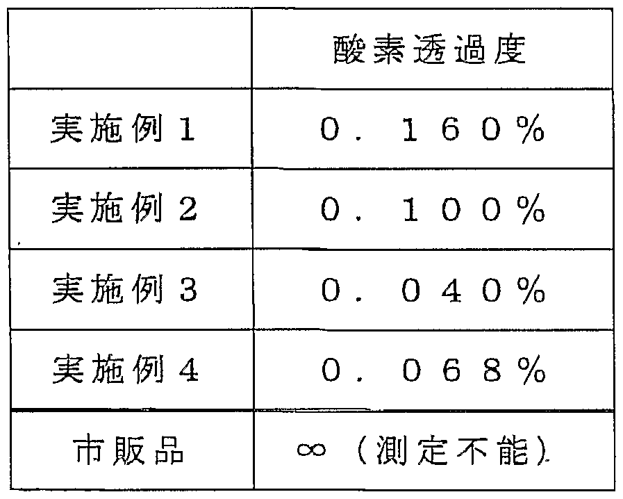


Claims
Priority Applications (7)
| Application Number | Priority Date | Filing Date | Title |
|---|---|---|---|
| KR1020047012885A KR100744854B1 (ko) | 2002-02-21 | 2003-02-20 | 밀봉 용기 |
| CA 2476797 CA2476797A1 (en) | 2002-02-21 | 2003-02-20 | Tightly covered container |
| JP2003569512A JPWO2003070592A1 (ja) | 2002-02-21 | 2003-02-20 | 密封容器 |
| NZ535409A NZ535409A (en) | 2002-02-21 | 2003-02-20 | Tightly covered container |
| US10/505,130 US20050236415A1 (en) | 2002-02-21 | 2003-02-20 | Hermetically sealed container |
| AU2003211568A AU2003211568B2 (en) | 2002-02-21 | 2003-02-20 | Tightly covered container |
| EP03705348A EP1486431A4 (en) | 2002-02-21 | 2003-02-20 | TIGHT COVERED CONTAINER |
Applications Claiming Priority (2)
| Application Number | Priority Date | Filing Date | Title |
|---|---|---|---|
| JP2002-45045 | 2002-02-21 | ||
| JP2002045045 | 2002-02-21 |
Publications (1)
| Publication Number | Publication Date |
|---|---|
| WO2003070592A1 true WO2003070592A1 (fr) | 2003-08-28 |
Family
ID=27750567
Family Applications (1)
| Application Number | Title | Priority Date | Filing Date |
|---|---|---|---|
| PCT/JP2003/001857 WO2003070592A1 (fr) | 2002-02-21 | 2003-02-20 | Contenant a couvercle ajuste |
Country Status (9)
| Country | Link |
|---|---|
| US (1) | US20050236415A1 (ja) |
| EP (1) | EP1486431A4 (ja) |
| JP (1) | JPWO2003070592A1 (ja) |
| KR (1) | KR100744854B1 (ja) |
| CN (1) | CN100572212C (ja) |
| AU (1) | AU2003211568B2 (ja) |
| CA (1) | CA2476797A1 (ja) |
| NZ (1) | NZ535409A (ja) |
| WO (1) | WO2003070592A1 (ja) |
Cited By (5)
| Publication number | Priority date | Publication date | Assignee | Title |
|---|---|---|---|---|
| JP2006016063A (ja) * | 2004-07-05 | 2006-01-19 | Nissin Food Prod Co Ltd | 生分解性即席食品用容器及びその製造方法 |
| EP1749056A1 (en) * | 2004-05-28 | 2007-02-07 | Youl Chon Chemical Co. Ltd. | Composition for biodegradable starch bowl and biodegradable starch bowl using the same |
| JP2009207439A (ja) * | 2008-03-05 | 2009-09-17 | Nissei Co Ltd | 容器入り即席麺の製造方法 |
| JP2009241342A (ja) * | 2008-03-31 | 2009-10-22 | Ako Kasei Co Ltd | デンプンを中芯とする生分解性デンプンラミネートシート |
| JP2019064657A (ja) * | 2017-09-29 | 2019-04-25 | 大日本印刷株式会社 | インスタント麺の包装容器の蓋 |
Families Citing this family (35)
| Publication number | Priority date | Publication date | Assignee | Title |
|---|---|---|---|---|
| ATE448160T1 (de) * | 2006-08-04 | 2009-11-15 | Lavazza Luigi Spa | Verschlossene kapsel zur herstellung eines getränks, insbesondere espresso |
| US20090236258A1 (en) * | 2008-02-25 | 2009-09-24 | Timothy John Connell | Pharmaceutical capsule container vial with window |
| BRPI0911299A2 (pt) * | 2008-04-14 | 2017-05-30 | Ethical Coffee Company Sa | cápsula para a preparação de uma bebida |
| US9738420B2 (en) * | 2008-05-14 | 2017-08-22 | Drayton Granville MILLER | “Green” temperature-controlled mailer |
| US20090283578A1 (en) * | 2008-05-14 | 2009-11-19 | Drayton Miller | "green" temperature- controlled mailer |
| BRPI0920315A2 (pt) * | 2008-10-08 | 2019-09-24 | Ethical Coffee Company Sa | capsula para o preparo de uma bebida |
| US8733551B2 (en) * | 2008-10-21 | 2014-05-27 | Medicart International Limited | Medical equipment storage and transportation kit |
| US20100332419A1 (en) * | 2009-06-24 | 2010-12-30 | The Coca-Cola Company | Product integrated fiber based package |
| CN103314156A (zh) * | 2010-06-15 | 2013-09-18 | Pakit国际贸易股份有限公司 | 在模制纤维产品上应用薄膜的方法以及通过所述方法制造的产品 |
| CA2890536C (en) * | 2012-02-22 | 2016-11-15 | Flatev Ag | Method and apparatus for automatic preparation of flat bread using capsules comprising a portion of dough |
| KR20130105463A (ko) * | 2012-03-14 | 2013-09-25 | 최우영 | 끓는 느낌을 부여하기 위한 즉석식품용 기포 발생제 및 이를 이용한 즉석식품 |
| US10131477B2 (en) | 2012-05-25 | 2018-11-20 | Stephen Robert | Container top with removable seal |
| DE102012111235B3 (de) * | 2012-11-21 | 2014-02-27 | Pedram Zolgadri | Einweggeschirr umfassend ein Laminat |
| CN103879684A (zh) * | 2012-12-24 | 2014-06-25 | 苏州工业园区咖乐美电器有限公司 | 一种速溶饮品的包装结构 |
| US9284691B2 (en) * | 2013-06-03 | 2016-03-15 | Friends Of Abilities First, Inc. | Paper pulping process and composition |
| US10472128B2 (en) * | 2014-07-18 | 2019-11-12 | Robert David Ciarrocchi | Hanging condiment cup with lid |
| CN105348640A (zh) * | 2015-11-11 | 2016-02-24 | 浙江捷宇塑料制品有限公司 | 一种高保温pp泡沫饭盒 |
| CN105330959A (zh) * | 2015-11-11 | 2016-02-17 | 浙江捷宇塑料制品有限公司 | 一种pp泡沫饭盒 |
| CN105330960A (zh) * | 2015-11-11 | 2016-02-17 | 浙江捷宇塑料制品有限公司 | 一种外壁多孔的pp泡沫饭盒 |
| JP6075587B1 (ja) * | 2016-02-12 | 2017-02-08 | みほ 東 | ネイル剤取り皿 |
| CN105541952B (zh) * | 2016-03-01 | 2017-11-14 | 重庆文理学院 | 一种水性达玛树脂及其制备方法、应用 |
| EP3541591B8 (en) * | 2016-11-18 | 2023-07-05 | Husky Injection Molding Systems Ltd. | Molded article, container and a method for the molding and recycling thereof |
| KR102319817B1 (ko) * | 2017-12-18 | 2021-11-02 | 주식회사 휴비스 | 내열성 및 가공성이 우수한 식품용기용 복합시트 및 이의 제조방법 |
| KR102225513B1 (ko) * | 2018-01-17 | 2021-03-11 | (주)네이쳐앤휴먼지피 | 내열성이 우수한 일회용 투명 뚜껑 |
| NL2021326B1 (en) | 2018-03-29 | 2019-10-07 | Huhtamaki Molded Fiber Tech Bv | Biodegradable and compostable food packaging unit from a moulded pulp material with a cellulose-base laminate layer, and method for manufacturing such food packaging unit |
| DK3774572T3 (da) * | 2018-03-29 | 2022-01-31 | Huhtamaki Molded Fiber Tech Bv | Pakkeenhed af et støbt pulpmateriale med aftrækkeligt laminatlag og fremgangsmåde til fremstilling af en sådan pakkeenhed |
| US10729261B2 (en) | 2018-09-28 | 2020-08-04 | Yeti Coolers, Llc | Bowl and method of forming a bowl |
| CN109748504A (zh) * | 2018-12-27 | 2019-05-14 | 山东乐和家日用品有限公司 | 满隔断保鲜盒及其制备方法 |
| US20200290786A1 (en) * | 2019-03-12 | 2020-09-17 | Chen Wei Wang | Environment protected starch container device |
| CN110282246B (zh) * | 2019-06-03 | 2020-09-08 | 虎彩印艺股份有限公司 | 一种耐热的可降解环保茶叶罐及其制备工艺 |
| US11820881B2 (en) | 2020-04-02 | 2023-11-21 | Singular Solutions Inc. | Plastic pro-biodegradation additives, biodegradable plastic compositions, and related methods |
| KR102324272B1 (ko) * | 2021-02-09 | 2021-11-10 | 주은케미칼 주식회사 | 고분자 시트 및 상기 고분자 시트로 형성되는 고분자 용기 |
| KR102385882B1 (ko) * | 2021-05-25 | 2022-04-14 | 이영진 | 천연고분자를 포함하는 내수성, 내열성 및 내유성이 우수한 생분해성 일회용 용기의 제조방법 및 이에 따라 제조된 천연고분자를 포함하는 생분해성 일회용 용기 |
| CN215044484U (zh) * | 2021-07-26 | 2021-12-07 | 苏州丰连实业有限公司 | 一种可降解的气调包装容器 |
| GB202215144D0 (en) * | 2022-10-13 | 2022-11-30 | Mccormick Uk Ltd | Packaging and methods of production thereof |
Citations (16)
| Publication number | Priority date | Publication date | Assignee | Title |
|---|---|---|---|---|
| JPH03109830U (ja) * | 1990-02-26 | 1991-11-12 | ||
| JPH04500833A (ja) * | 1989-08-03 | 1992-02-13 | ノバモント・ソシエタ・ペル・アチオニ | 生分解性プラスチック材料製発泡物品およびその製造方法 |
| JPH04352653A (ja) * | 1991-05-28 | 1992-12-07 | Toppan Printing Co Ltd | 廃棄性に優れた包装材料 |
| JPH0557833A (ja) * | 1991-01-25 | 1993-03-09 | Jsp Corp | 微生物分解性多層シート |
| JPH05230272A (ja) * | 1992-02-18 | 1993-09-07 | Asahi Chem Ind Co Ltd | 表面処理された澱粉系発泡体 |
| JPH05278738A (ja) * | 1992-04-06 | 1993-10-26 | Nishikawa Rubber Co Ltd | 生分解性容器 |
| JPH06126897A (ja) * | 1991-12-27 | 1994-05-10 | Kyoraku Co Ltd | 包装用多層構造体 |
| JPH07285192A (ja) * | 1994-04-19 | 1995-10-31 | Dainippon Printing Co Ltd | 樹脂積層体 |
| JPH08500547A (ja) * | 1992-08-28 | 1996-01-23 | ビオテック・ビオロギッシュ・ナトゥフェアパックンゲン・ゲゼルシャフト・ミット・ベシュレンクテル・ハフツング・ウント・コンパニ・フォルシュンクス−・ウント・エントヴィックルンクス・コマンディット・ゲゼルシャフト | 硬化デンプン発泡体をベースにした生分解性積層複合材料およびその製造方法 |
| JPH11268751A (ja) * | 1998-03-18 | 1999-10-05 | Takushoku Shoji:Kk | 生分解性袋 |
| JP3009261B2 (ja) * | 1991-08-19 | 2000-02-14 | 中央化学株式会社 | 防湿澱粉成形物 |
| JP2001079816A (ja) * | 1999-09-09 | 2001-03-27 | Seibu Electric & Mach Co Ltd | 生分解性材料製容器の製造方法 |
| JP3160607B2 (ja) * | 1992-11-24 | 2001-04-25 | 経済産業省産業技術総合研究所長 | 生分解性の熱可塑性樹脂製器具 |
| JP2001151280A (ja) * | 1999-11-29 | 2001-06-05 | Best Pack Kk | 即席麺の容器 |
| JP2001302835A (ja) * | 2000-04-26 | 2001-10-31 | Shimadzu Corp | 生分解性発泡体及びその製造方法 |
| JP2002173182A (ja) * | 2000-12-01 | 2002-06-18 | Sanwa Kosan Kk | 複合容器 |
Family Cites Families (13)
| Publication number | Priority date | Publication date | Assignee | Title |
|---|---|---|---|---|
| GB8528428D0 (en) * | 1985-11-19 | 1985-12-24 | Bunzl Flexpack Ltd | Packaging of fresh fruit & vegetables |
| US4885897A (en) * | 1987-01-16 | 1989-12-12 | Toyo Seikan Kaisha, Limited | Method of making hermetically sealed container |
| US5288765A (en) * | 1989-08-03 | 1994-02-22 | Spherilene S.R.L. | Expanded articles of biodegradable plastics materials and a method for their production |
| US5512333A (en) * | 1992-10-16 | 1996-04-30 | Icd Industries | Method of making and using a degradable package for containment of liquids |
| US5888599A (en) * | 1993-04-19 | 1999-03-30 | E. I. Du Pont De Nemours And Company | Multi-layer lidding film having improved heat seal properties and methods relating thereto |
| JP3474031B2 (ja) * | 1994-07-11 | 2003-12-08 | 日世株式会社 | 生分解性成形物の製造方法 |
| NL9401283A (nl) * | 1994-08-05 | 1996-03-01 | Avebe Coop Verkoop Prod | Biodegradeerbaar vormstuk dat geschikt is om vloeibare of min of meer vaste food of non-food produkten te houden zonder dat de stevigheid van het vormstuk verloren gaat, alsmede werkwijze voor het vervaardigen van een dergelijk vormstuk. |
| US5919547A (en) * | 1995-06-06 | 1999-07-06 | Cryovac, Inc. | Laminate having a coextruded, multilayer film which delaminates and package made therefrom |
| CN1153518C (zh) * | 1995-06-14 | 2004-06-16 | 弗朗兹哈斯华夫饼干机械工业股份公司 | 制备可降解薄壁模塑物的方法 |
| US5861216A (en) * | 1996-06-28 | 1999-01-19 | The United States Of America As Represented By The Secretary Of Agriculture | Biodegradable polyester and natural polymer laminates |
| US6068864A (en) * | 1996-07-12 | 2000-05-30 | Kraft Foods, Inc. | Method of imparting resistance to moisture and texture degradation to a baked product |
| US5797984A (en) * | 1997-04-15 | 1998-08-25 | National Starch And Chemical Investment Holding Corporation | Water resistant starch based foams |
| KR20000057885A (ko) * | 1999-02-10 | 2000-09-25 | 모리 테 쯔로오 | 생분해성재료 조성물, 이 조성물로부터 제조된생분해성재료제용기 및 이 생분해성재료제용기의 제조방법 |
-
2003
- 2003-02-20 CA CA 2476797 patent/CA2476797A1/en not_active Abandoned
- 2003-02-20 KR KR1020047012885A patent/KR100744854B1/ko not_active IP Right Cessation
- 2003-02-20 CN CNB038043777A patent/CN100572212C/zh not_active Expired - Fee Related
- 2003-02-20 EP EP03705348A patent/EP1486431A4/en not_active Withdrawn
- 2003-02-20 WO PCT/JP2003/001857 patent/WO2003070592A1/ja active Application Filing
- 2003-02-20 JP JP2003569512A patent/JPWO2003070592A1/ja active Pending
- 2003-02-20 US US10/505,130 patent/US20050236415A1/en not_active Abandoned
- 2003-02-20 NZ NZ535409A patent/NZ535409A/en not_active IP Right Cessation
- 2003-02-20 AU AU2003211568A patent/AU2003211568B2/en not_active Ceased
Patent Citations (16)
| Publication number | Priority date | Publication date | Assignee | Title |
|---|---|---|---|---|
| JPH04500833A (ja) * | 1989-08-03 | 1992-02-13 | ノバモント・ソシエタ・ペル・アチオニ | 生分解性プラスチック材料製発泡物品およびその製造方法 |
| JPH03109830U (ja) * | 1990-02-26 | 1991-11-12 | ||
| JPH0557833A (ja) * | 1991-01-25 | 1993-03-09 | Jsp Corp | 微生物分解性多層シート |
| JPH04352653A (ja) * | 1991-05-28 | 1992-12-07 | Toppan Printing Co Ltd | 廃棄性に優れた包装材料 |
| JP3009261B2 (ja) * | 1991-08-19 | 2000-02-14 | 中央化学株式会社 | 防湿澱粉成形物 |
| JPH06126897A (ja) * | 1991-12-27 | 1994-05-10 | Kyoraku Co Ltd | 包装用多層構造体 |
| JPH05230272A (ja) * | 1992-02-18 | 1993-09-07 | Asahi Chem Ind Co Ltd | 表面処理された澱粉系発泡体 |
| JPH05278738A (ja) * | 1992-04-06 | 1993-10-26 | Nishikawa Rubber Co Ltd | 生分解性容器 |
| JPH08500547A (ja) * | 1992-08-28 | 1996-01-23 | ビオテック・ビオロギッシュ・ナトゥフェアパックンゲン・ゲゼルシャフト・ミット・ベシュレンクテル・ハフツング・ウント・コンパニ・フォルシュンクス−・ウント・エントヴィックルンクス・コマンディット・ゲゼルシャフト | 硬化デンプン発泡体をベースにした生分解性積層複合材料およびその製造方法 |
| JP3160607B2 (ja) * | 1992-11-24 | 2001-04-25 | 経済産業省産業技術総合研究所長 | 生分解性の熱可塑性樹脂製器具 |
| JPH07285192A (ja) * | 1994-04-19 | 1995-10-31 | Dainippon Printing Co Ltd | 樹脂積層体 |
| JPH11268751A (ja) * | 1998-03-18 | 1999-10-05 | Takushoku Shoji:Kk | 生分解性袋 |
| JP2001079816A (ja) * | 1999-09-09 | 2001-03-27 | Seibu Electric & Mach Co Ltd | 生分解性材料製容器の製造方法 |
| JP2001151280A (ja) * | 1999-11-29 | 2001-06-05 | Best Pack Kk | 即席麺の容器 |
| JP2001302835A (ja) * | 2000-04-26 | 2001-10-31 | Shimadzu Corp | 生分解性発泡体及びその製造方法 |
| JP2002173182A (ja) * | 2000-12-01 | 2002-06-18 | Sanwa Kosan Kk | 複合容器 |
Non-Patent Citations (1)
| Title |
|---|
| See also references of EP1486431A4 * |
Cited By (7)
| Publication number | Priority date | Publication date | Assignee | Title |
|---|---|---|---|---|
| EP1749056A1 (en) * | 2004-05-28 | 2007-02-07 | Youl Chon Chemical Co. Ltd. | Composition for biodegradable starch bowl and biodegradable starch bowl using the same |
| EP1749056A4 (en) * | 2004-05-28 | 2011-07-13 | Youl Chon Chemical Co Ltd | COMPOSITION FOR BIODEGRADABLE STARCH TANK AND BIODEGRADABLE STARCH TANK USING THE SAME COMPOSITION |
| JP2006016063A (ja) * | 2004-07-05 | 2006-01-19 | Nissin Food Prod Co Ltd | 生分解性即席食品用容器及びその製造方法 |
| JP4659402B2 (ja) * | 2004-07-05 | 2011-03-30 | 日清食品ホールディングス株式会社 | 生分解性即席食品用容器の製造方法 |
| JP2009207439A (ja) * | 2008-03-05 | 2009-09-17 | Nissei Co Ltd | 容器入り即席麺の製造方法 |
| JP2009241342A (ja) * | 2008-03-31 | 2009-10-22 | Ako Kasei Co Ltd | デンプンを中芯とする生分解性デンプンラミネートシート |
| JP2019064657A (ja) * | 2017-09-29 | 2019-04-25 | 大日本印刷株式会社 | インスタント麺の包装容器の蓋 |
Also Published As
| Publication number | Publication date |
|---|---|
| EP1486431A4 (en) | 2009-05-06 |
| US20050236415A1 (en) | 2005-10-27 |
| NZ535409A (en) | 2006-09-29 |
| CA2476797A1 (en) | 2003-08-28 |
| AU2003211568B2 (en) | 2008-09-18 |
| AU2003211568A1 (en) | 2003-09-09 |
| CN100572212C (zh) | 2009-12-23 |
| CN1639022A (zh) | 2005-07-13 |
| KR100744854B1 (ko) | 2007-08-01 |
| EP1486431A1 (en) | 2004-12-15 |
| JPWO2003070592A1 (ja) | 2005-06-09 |
| KR20040089644A (ko) | 2004-10-21 |
Similar Documents
| Publication | Publication Date | Title |
|---|---|---|
| WO2003070592A1 (fr) | Contenant a couvercle ajuste | |
| JP4291699B2 (ja) | 生分解性成形物 | |
| JP3961421B2 (ja) | 生分解性成形物およびその製造方法、並びに発泡成形用組成物 | |
| JP4121874B2 (ja) | 生分解性成形物の製造方法およびそれに用いる成形型 | |
| JP2003191264A (ja) | 生分解性成形物の製造方法 |
Legal Events
| Date | Code | Title | Description |
|---|---|---|---|
| AK | Designated states |
Kind code of ref document: A1 Designated state(s): AE AG AL AM AT AU AZ BA BB BG BR BY BZ CA CH CN CO CR CU CZ DE DK DM DZ EC EE ES FI GB GD GE GH GM HR HU ID IL IN IS JP KE KG KP KR KZ LC LK LR LS LT LU LV MA MD MG MK MN MW MX MZ NO NZ OM PH PL PT RO RU SC SD SE SG SK SL TJ TM TN TR TT TZ UA UG US UZ VC VN YU ZA ZM ZW |
|
| AL | Designated countries for regional patents |
Kind code of ref document: A1 Designated state(s): GH GM KE LS MW MZ SD SL SZ TZ UG ZM ZW AM AZ BY KG KZ MD RU TJ TM AT BE BG CH CY CZ DE DK EE ES FI FR GB GR HU IE IT LU MC NL PT SE SI SK TR BF BJ CF CG CI CM GA GN GQ GW ML MR NE SN TD TG |
|
| DFPE | Request for preliminary examination filed prior to expiration of 19th month from priority date (pct application filed before 20040101) | ||
| 121 | Ep: the epo has been informed by wipo that ep was designated in this application | ||
| WWE | Wipo information: entry into national phase |
Ref document number: 2003569512 Country of ref document: JP |
|
| WWE | Wipo information: entry into national phase |
Ref document number: 2476797 Country of ref document: CA |
|
| WWE | Wipo information: entry into national phase |
Ref document number: 1020047012885 Country of ref document: KR |
|
| WWE | Wipo information: entry into national phase |
Ref document number: 20038043777 Country of ref document: CN |
|
| WWE | Wipo information: entry into national phase |
Ref document number: 2003211568 Country of ref document: AU |
|
| WWE | Wipo information: entry into national phase |
Ref document number: 2003705348 Country of ref document: EP |
|
| WWE | Wipo information: entry into national phase |
Ref document number: 535409 Country of ref document: NZ |
|
| WWP | Wipo information: published in national office |
Ref document number: 2003705348 Country of ref document: EP |
|
| WWE | Wipo information: entry into national phase |
Ref document number: 10505130 Country of ref document: US |