WO1999053693A1 - Systeme multivision, procede d'etalonnage de couleurs et visualisation - Google Patents
Systeme multivision, procede d'etalonnage de couleurs et visualisation Download PDFInfo
- Publication number
- WO1999053693A1 WO1999053693A1 PCT/JP1998/001709 JP9801709W WO9953693A1 WO 1999053693 A1 WO1999053693 A1 WO 1999053693A1 JP 9801709 W JP9801709 W JP 9801709W WO 9953693 A1 WO9953693 A1 WO 9953693A1
- Authority
- WO
- WIPO (PCT)
- Prior art keywords
- color
- color conversion
- conversion coefficient
- display
- colors
- Prior art date
Links
Classifications
-
- H—ELECTRICITY
- H04—ELECTRIC COMMUNICATION TECHNIQUE
- H04N—PICTORIAL COMMUNICATION, e.g. TELEVISION
- H04N17/00—Diagnosis, testing or measuring for television systems or their details
- H04N17/04—Diagnosis, testing or measuring for television systems or their details for receivers
-
- H—ELECTRICITY
- H04—ELECTRIC COMMUNICATION TECHNIQUE
- H04N—PICTORIAL COMMUNICATION, e.g. TELEVISION
- H04N17/00—Diagnosis, testing or measuring for television systems or their details
- H04N17/02—Diagnosis, testing or measuring for television systems or their details for colour television signals
-
- H—ELECTRICITY
- H04—ELECTRIC COMMUNICATION TECHNIQUE
- H04N—PICTORIAL COMMUNICATION, e.g. TELEVISION
- H04N9/00—Details of colour television systems
- H04N9/12—Picture reproducers
- H04N9/31—Projection devices for colour picture display, e.g. using electronic spatial light modulators [ESLM]
- H04N9/3141—Constructional details thereof
- H04N9/3147—Multi-projection systems
-
- H—ELECTRICITY
- H04—ELECTRIC COMMUNICATION TECHNIQUE
- H04N—PICTORIAL COMMUNICATION, e.g. TELEVISION
- H04N9/00—Details of colour television systems
- H04N9/12—Picture reproducers
- H04N9/31—Projection devices for colour picture display, e.g. using electronic spatial light modulators [ESLM]
- H04N9/3191—Testing thereof
- H04N9/3194—Testing thereof including sensor feedback
-
- G—PHYSICS
- G06—COMPUTING; CALCULATING OR COUNTING
- G06F—ELECTRIC DIGITAL DATA PROCESSING
- G06F3/00—Input arrangements for transferring data to be processed into a form capable of being handled by the computer; Output arrangements for transferring data from processing unit to output unit, e.g. interface arrangements
- G06F3/14—Digital output to display device ; Cooperation and interconnection of the display device with other functional units
- G06F3/1423—Digital output to display device ; Cooperation and interconnection of the display device with other functional units controlling a plurality of local displays, e.g. CRT and flat panel display
- G06F3/1446—Digital output to display device ; Cooperation and interconnection of the display device with other functional units controlling a plurality of local displays, e.g. CRT and flat panel display display composed of modules, e.g. video walls
-
- G—PHYSICS
- G09—EDUCATION; CRYPTOGRAPHY; DISPLAY; ADVERTISING; SEALS
- G09G—ARRANGEMENTS OR CIRCUITS FOR CONTROL OF INDICATING DEVICES USING STATIC MEANS TO PRESENT VARIABLE INFORMATION
- G09G2320/00—Control of display operating conditions
- G09G2320/06—Adjustment of display parameters
- G09G2320/0606—Manual adjustment
-
- G—PHYSICS
- G09—EDUCATION; CRYPTOGRAPHY; DISPLAY; ADVERTISING; SEALS
- G09G—ARRANGEMENTS OR CIRCUITS FOR CONTROL OF INDICATING DEVICES USING STATIC MEANS TO PRESENT VARIABLE INFORMATION
- G09G2320/00—Control of display operating conditions
- G09G2320/06—Adjustment of display parameters
- G09G2320/0666—Adjustment of display parameters for control of colour parameters, e.g. colour temperature
-
- G—PHYSICS
- G09—EDUCATION; CRYPTOGRAPHY; DISPLAY; ADVERTISING; SEALS
- G09G—ARRANGEMENTS OR CIRCUITS FOR CONTROL OF INDICATING DEVICES USING STATIC MEANS TO PRESENT VARIABLE INFORMATION
- G09G2320/00—Control of display operating conditions
- G09G2320/06—Adjustment of display parameters
- G09G2320/0693—Calibration of display systems
-
- G—PHYSICS
- G09—EDUCATION; CRYPTOGRAPHY; DISPLAY; ADVERTISING; SEALS
- G09G—ARRANGEMENTS OR CIRCUITS FOR CONTROL OF INDICATING DEVICES USING STATIC MEANS TO PRESENT VARIABLE INFORMATION
- G09G2340/00—Aspects of display data processing
- G09G2340/06—Colour space transformation
-
- G—PHYSICS
- G09—EDUCATION; CRYPTOGRAPHY; DISPLAY; ADVERTISING; SEALS
- G09G—ARRANGEMENTS OR CIRCUITS FOR CONTROL OF INDICATING DEVICES USING STATIC MEANS TO PRESENT VARIABLE INFORMATION
- G09G2360/00—Aspects of the architecture of display systems
- G09G2360/14—Detecting light within display terminals, e.g. using a single or a plurality of photosensors
- G09G2360/145—Detecting light within display terminals, e.g. using a single or a plurality of photosensors the light originating from the display screen
-
- G—PHYSICS
- G09—EDUCATION; CRYPTOGRAPHY; DISPLAY; ADVERTISING; SEALS
- G09G—ARRANGEMENTS OR CIRCUITS FOR CONTROL OF INDICATING DEVICES USING STATIC MEANS TO PRESENT VARIABLE INFORMATION
- G09G5/00—Control arrangements or circuits for visual indicators common to cathode-ray tube indicators and other visual indicators
- G09G5/02—Control arrangements or circuits for visual indicators common to cathode-ray tube indicators and other visual indicators characterised by the way in which colour is displayed
Definitions
- the present invention relates to color calibration of a multi-vision system including a display device and a plurality of display devices.
- FIGS. 16 and 17 are a partial cross-sectional view and a block diagram of a main part of a conventional multi-vision brightness control device including a plurality of display devices disclosed in Japanese Patent Application Laid-Open No. 7-72817, for example. is there.
- Fig. 18 is a flowchart of the operation of the multi-vision brightness control device.
- R1 is a screen
- R3 is a sensor that detects the brightness of the outer periphery
- R5 is a wall
- R6 is a ceiling
- R7 is a storage shelf
- R31 is a skylight
- R8 is the projection unit
- R9 is the lens block of the projection unit R8
- R10 is the control board of the projection unit R8
- R11 is the projection tube of the projection unit R8,
- R12 is
- the operation panel R13 of the projection unit R8 is a lead wire for transmitting the signal of the sensor R3 to the control board.
- a sensor R3 is provided on the outer periphery of the screen frame to detect the brightness of the light beam applied to the screen frame.
- the luminance information detected by the sensor R 3 is The signal is sent to the control board R10 by the lead wire R13, stored and calculated, and the brightness is set to the tube tube R11.
- each storage device in the control circuit is cleared to zero, the time counter t is cleared to zero after a certain time, the surrounding brightness is detected by the sensor R3, and the surrounding brightness information is read from the control board R1. Input 0 to lead 13.
- the control board R 10 performs an operation designed to minimize the brightness value of the cathode ray tube R 11 according to the surrounding brightness based on the surrounding brightness information so as to make it easy to see, and the calculated result is sent to the cathode ray tube. Input and set the brightness and project the image on the screen. After that, if the device is stopped, stop the process. If not, repeat the process from detecting the brightness again.
- the luminance is controlled as described above. Since the information obtained by the sensor R3 is only luminance information, only the optimal luminance can be set according to the surrounding environment at that time, and the display color cannot be controlled.
- the sensor R3 is not set for each screen, even if there is a difference in display color between screens, it cannot be detected, so that color control for each screen cannot be performed. However, display was possible only with uneven color.
- An object of the present invention is to match a display color of a display device with a target color.
- Another object of the present invention is to match the display colors of a plurality of display devices in a multi-vision system with the same target color to eliminate the difference in colors displayed between the display devices. Further, it is an object of the present invention to optimally select a target color as a target for matching the display colors of a plurality of display devices in a multi-vision system, and to improve the overall color matching performance.
- a multi-vision system is a multi-vision system including a plurality of display devices.
- a sensor for measuring display colors of a plurality of display devices A sensor for measuring display colors of a plurality of display devices
- a color conversion coefficient calculation unit that calculates a color conversion coefficient for calibrating the display color of each display device from the colorimetric values of the display colors of the plurality of display devices measured by the sensor,
- a color processing unit that performs color conversion of the display color of each display device using the color conversion coefficient calculated by the color conversion coefficient calculation unit;
- the color processing unit receives a signal of at least one or more representative colors, displays the representative color on a display device without color conversion,
- the sensor measures a representative color displayed on the plurality of display devices by the color processing unit
- the color conversion coefficient calculation unit calculates a color conversion coefficient of each display device for performing color conversion so that the representative color measured by the sensor becomes a predetermined target color, and calculates the calculated color conversion coefficient. Is output to the color processing unit.
- the sensor is built in a multi-vision system and is installed in a non-display area between a plurality of display devices.
- the sensor is installed outside the multi-vision system.
- the sensor is installed so as to be capable of parallel scanning with respect to a plurality of display devices.
- the color conversion coefficient calculation unit determines signal values of at least one or more representative colors, and calculates a colorimetric value of the representative color when the representative colors are displayed on a plurality of display devices without color conversion. Among them, a colorimetric value which can maximize a common color gamut within a color gamut of a plurality of display devices is set as a target color of the representative color.
- the color conversion coefficient calculator displays colorimetric values of at least one or more representative colors of a plurality of display devices on chromaticity coordinates, and determines a target color based on the designated chromaticity coordinates. It is characterized by.
- the color conversion coefficient calculation unit determines in advance signal values of at least one or more representative colors, and measures the colorimetric values of the representative colors when the representative colors are displayed on a plurality of display devices without color conversion. In this method, the colorimetric value with the smallest saturation is set as the target color of the representative color.
- the color conversion coefficient calculation unit previously determines signal values of at least one or more representative colors, and measures colorimetric values of the representative colors when the representative colors are displayed on a plurality of display devices without color conversion. The average value is used as the target color of the representative color.
- the multi-vision system includes a memory that stores a colorimetric value of each display device and a chromaticity value of a target color, and the color conversion coefficient calculation unit includes a colorimetric value obtained at the next calibration. The value is compared with one of the previous colorimetric value and the chromaticity value of the target color, and when there is a difference equal to or more than a predetermined value, a color conversion coefficient is calculated.
- the above multi-vision system uses the colorimetric values and A memory for storing the chromaticity value of the target color; and the color conversion coefficient calculating section calculates the colorimetric value obtained at the next calibration by using the previous colorimetric value and the chromaticity of the target color.
- a display device having a difference equal to or more than a predetermined value is compared with any of the display devices, and a color conversion coefficient of the selected display device is calculated.
- the display device is a display device that displays colors by mixing primary colors
- a sensor for measuring the display color of the display device A sensor for measuring the display color of the display device
- a color conversion coefficient calculation unit that calculates a color conversion coefficient for calibrating the display color of the display device from the colorimetric value of the display color of the display device measured by the sensor;
- a color processing unit that performs color conversion of the display color of each display device using the color conversion coefficient calculated by the color conversion coefficient calculation unit;
- the color processing unit receives a signal of at least one or more representative colors, displays the representative color on a display device without color conversion,
- the sensor measures a representative color on the display device displayed by the color processing unit
- the color conversion coefficient calculation unit calculates a color conversion coefficient for performing color conversion so that the representative color measured by the sensor becomes a target color in advance, and outputs the calculated color conversion coefficient to the color processing unit. It is characterized by doing.
- the color conversion coefficient calculator calculates a color conversion coefficient using a three-dimensional space.
- the color conversion coefficient calculation unit is characterized in that a color conversion coefficient is calculated using XYZ tristimulus values of colors obtained by mixing the three primary colors in the additive color mixing model.
- a color calibration method for a multi-vision system according to the present invention is a color calibration method for a multi-vision system comprising a plurality of display devices.
- the color processing step includes a step of receiving a signal of at least one or more representative colors and displaying the representative colors on a display device without color conversion, and the sensor step is performed by the color processing step.
- the color conversion coefficient calculation step includes a step of calculating a color conversion coefficient of each display device for performing color conversion so that the representative color measured by the sensor becomes a predetermined target color; and a step of calculating the calculated color conversion coefficient. A step of outputting the coefficient to the color processing step.
- FIG. 1 is an overall block diagram according to Embodiment 1 of the present invention.
- FIG. 2 is a flowchart of the color calibration process according to the first embodiment of the present invention.
- FIG. 3 is a flowchart of a color calibration process according to the first embodiment of the present invention.
- FIG. 4 shows a color calibration according to the first embodiment of the present invention.
- FIG. 3 is a diagram showing a target color determined in the step (a).
- FIG. 5 is a diagram showing a target color determined in the color calibration according to the first embodiment of the present invention.
- FIG. 6 is an overall block diagram according to Embodiment 2 of the present invention.
- FIG. 7 is an overall block diagram according to Embodiment 3 of the present invention.
- FIG. 8 is a flowchart of a color calibration process according to the third embodiment of the present invention.
- FIG. 9 is a flowchart of a color calibration process according to the third embodiment of the present invention.
- FIG. 10 is an overall block diagram according to Embodiment 4 of the present invention.
- FIG. 11 is a diagram showing a display monitor screen showing a color measurement result and a determined target color in the color calibration according to the fourth embodiment of the present invention.
- FIG. 12 is an overall block diagram according to Embodiment 5 of the present invention.
- FIG. 13 is a flowchart of a color calibration process according to the fifth embodiment of the present invention.
- FIG. 14 is a flowchart of a color calibration process according to the fifth embodiment of the present invention.
- FIG. 15 is a flowchart for the execution determination of calibration according to the fifth embodiment of the present invention.
- FIG. 16 is a diagram showing a conventional multi-vision system.
- FIG. 17 is a diagram showing a conventional multi-vision system.
- FIG. 18 is a diagram showing the operation of a conventional multi-vision system. BEST MODE FOR CARRYING OUT THE INVENTION
- Embodiment 1 Hereinafter, Embodiment 1 of the present invention will be described with reference to the drawings.
- FIG. 1 is an overall block diagram of a multi-vision system having a color calibration function according to an embodiment of the present invention.
- reference numeral 1 denotes an outline of a multi-vision system.
- 2 is a projector unit and 3 is a screen unit.
- One screen unit 3 corresponds to one project unit 2.
- the input video analog signal is enlarged and divided by a magnifier 9 to create a video signal for each projector unit 2, and is input to the projector unit 2 via a color processing unit 8.
- the chromaticity sensors 4 are installed between the screen units 3 to measure the color of the light source that has not been color-converted by the corresponding color processing unit 8 of the projector unit 2.
- the position is set so that
- the calibration unit 5 includes a system control unit 6 and a color conversion coefficient calculation unit 7.
- the system control unit 6 controls a series of processes of the projector unit 2, the chromaticity sensor 4, the color conversion coefficient calculation unit 7, and the color processing unit 8 in the color calibration.
- the color conversion coefficient calculator 7 determines the target color from the XYZ tristimulus values of the color of the light source of each projector unit 2 obtained by the chromaticity sensor 4, and determines the color of the light source of each projector unit 2. Is converted to the target color and the color conversion coefficient for unification is calculated.
- the calculated color conversion coefficients are stored in the color processing unit 8 corresponding to each projector unit 1 on a one-to-one basis.
- the projector and screen unit 3 are treated as a set with the concept of a display
- Equation 1 shows that the color space of a display in which additive color mixing is established is a linear space.
- Equation 1 is the XYZ tristimulus value X of the color C obtained by mixing the three primary colors R (red), G (green), and B (blue).
- Y c , and Z e represent the linear sum of the X, Y, and Z tristimulus values of the three primary colors R, G, and B, respectively.
- the XYZ tristimulus values of the primary color R X r, Y r, Z r likewise the XYZ tristimulus values of the primary color G X g, Y g, Z g, likewise the XY Z tristimulus values of the primary color B X b, Y b, represented by Z b.
- Equation 2 ⁇ , ⁇ , and ⁇ can be expressed as Equation 2 as scalar quantities representing the light intensity.
- RGB d is the digital input signal of R, G, and B.
- f r , f e , f b are R,
- Equations 1 and 2 if the XYZ tristimulus values of the three primary colors R, G, and B are known, the digital input signal (R d , G d , B d ) for displaying a certain color C
- the XYZ tristimulus values for color C could be calculated.
- the coefficients ⁇ , ⁇ , 0 are the ratios of each primary color to the maximum emission brightness , Both have a value between 0 and 1.
- ff b is represented by a higher-order function, but here, for simplicity, an optical device that can be represented by a linear function Describe.
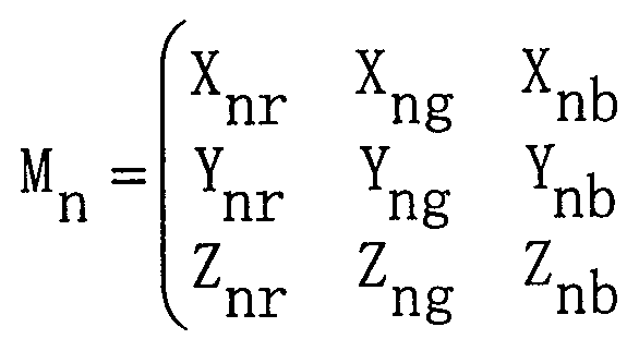
- Equation 1 the matrix of Equation 1 is defined as shown in Equations 3, 4, and 5 below.
- Equation 3 defines the Matrix display of the XYZ tristimulus value for color C on the nth display.
- Equation 4 defines the matrix display of the XYZ tristimulus values of the R, G, and B primary colors on the nth display.
- Equation 5 defines the matrix display of the ratio (scalar quantity representing the light intensity) to the maximum emission luminance of each primary color of the n-th display alone.
- Equation 6 the XYZ tristimulus values of a certain color Cn of the nth display device are expressed as shown in Equation 6.
- Equation 6 is an expression that expresses Equation 1 in the matrix display defined by Equations 3, 4, and 5.
- Equation 6 " ⁇ " represents the product of matrices (the same applies hereinafter). Equation 6
- M n represents a conversion matrix from the digital values of R, G, and B of the input signal to XYZ tristimulus values of the color.
- This matrix M n is specific to each display device when the input signals are equal but the colors displayed by each display device are different.
- Equation 7 shows that the color processing unit 8 performs color conversion by multiplying the input signal by the color conversion coefficient Mnt and outputs a color in the common color reproduction area. Equation 7 shows that the ratio (scalar amount indicating light intensity) of each primary color to the maximum emission luminance of each primary color alone is multiplied by the color conversion coefficient M nt to convert it into the color (target color) of the common color reproduction area. Is an expression showing Now, representing the XYZ tristimulus values of the common color reproduction area in c t.
- a color conversion coefficient M nt is obtained and stored in the color processing unit 8.
- Equation 7 Mnt considers the three primary colors R, G, and B in Equation 7. Can be calculated most easily. Assuming that the ratio of each primary color to the maximum emission luminance when each of the three primary colors R, G, and B is displayed separately is D, D n , is expressed as a unit matrix as shown in Equation 8.
- Equation 8 is an equation that shows the ratio of each primary color to the maximum emission luminance when the three primary colors R, G, and B are separately displayed by extending Equation 5.
- f r (R r ), f g (G r ), and f b (B r ) are ratios to the maximum emission luminance when the primary color R is displayed.
- f r (R g ), f g (G g ), and f b (B g ) are ratios to the maximum emission luminance when the primary color G is displayed.
- f r (R b ), f g (G b ), and f b (B b ) are ratios with respect to the maximum emission luminance when the primary color B is displayed.
- Equation 9 is an extension of Equation 7 when the three primary colors R, G, and B are displayed separately, as in Equation 8.
- the Mnt that is finally obtained is obtained by transforming Equation 9. Equation 1 0
- M n 1 represents the inverse of the matrix M n .
- This equation 10 is an equation for calculating the color conversion coefficient Mnt desired to be finally obtained.
- D n cannot be represented by a unit matrix, and thus the values of the respective elements of Equation 8 are specifically obtained.
- D n , _1 represents an inverse matrix of the matrix D n ,.
- the color calibration is to determine the color conversion coefficient Mnt in the color processing unit in this system.
- the color calibration method executed by the system control unit 6 will be described in detail with reference to the flowcharts of FIGS.
- black (BK) and the primary colors R, G, and B are sequentially displayed on the entire screen.
- black (BK) is displayed is to consider a black floating phenomenon described later. If the black floating phenomenon is not considered, it is not necessary to display black (BK).
- Each input signal value (R d , G d , B d ) is
- the color conversion coefficient calculator 7 stores the XYZ tristimulus values of a plurality of sensors, and calculates the average of the XYZ tristimulus values of all the display devices after the measurement is completed m times (SI 1 to S15). The calculated value is used when considering a black floating phenomenon described later.
- the above processing is performed for all the R, G, and B primary colors (S 21 to S 25, S 31 to S 35, S 41 to S 45). Mn of 4 is required. The obtained Mn is used in the expression 10 for obtaining the color conversion coefficient Mnt .
- the target color is set in the color conversion coefficient calculator 7 (S5).
- the value of the XYZ tristimulus value of the colorimetric value with the smallest saturation the set as target color XY Z tristimulus values c t of.
- the method for determining the colorimetric value with the smallest saturation is to determine the distance between a plurality of points in the XYZ space, which is a three-dimensional space, and the achromatic axis represented by a straight line.
- ynr Y n ( X nr + Y nr + Z nr)
- the achromatic axis is also one point and is represented by two variables. If the coordinates are expressed as (x Q , y.), The smallest value of the colorimetric values is the colorimetric value with the smallest distance from the achromatic point.
- the point of the chromaticity coordinates (x nr , y nr ) where the value calculated by the equation 12 is the minimum is defined as the chromaticity coordinates of the target color.
- the value of Y is set.
- the value of X nr , Z nr is calculated by directly using Y nr of (x nr , y felicit r ) of the display n having the minimum value calculated by Equation 12.
- This primary colors G similarly performed for B, the target color of the XYZ tristimulus values of each primary color (X tg, Y tg, Z tg), determine the (X tb, Y tb, z tb). Since it is difficult to illustrate the above in a three-dimensional space, it is shown in FIG. 4 on a two-dimensional xy chromaticity diagram for simplicity.
- FIG. 4 shows an example of three display devices for the sake of simplicity.
- the left side shows the colorimetric results
- the right side shows the chromaticity coordinates of the determined target color in black dots.
- the black dot reference indicates that among the colorimetric values Rl, R2, and R3 of the primary colors R of the three display devices, R3 having the smallest saturation is the chromaticity coordinates of the target color. I have.
- there is the following method for setting other target colors From the XYZ tristimulus values of the colorimetric results of all n display devices, calculate the value that is the average value (that is, the center of gravity) for each representative color, and calculate it as the XYZ tristimulus of the target color. Set as a value.
- XYZ tristimulus values of the representative color R of the display device and n (X nr, Y nr, Z nr) When expressed by the target color XY Z tristimulus values of the primary colors R (X tr, Y tr, Z tr ) is as shown in Equation 13.
- Equation 13 is the average of the X, Y, and Z tristimulus values for the representative color R of all displays.
- This calculation primary colors G similarly performed for B, the target color of the XYZ tristimulus values of each primary color (X tg, Y tg, Z tg), determine the (X tb, Y tb, Z tb). Since it is difficult to illustrate the above in a three-dimensional space, the two-dimensional xy chromaticity diagram shown in Fig. 5 for simplicity is as shown in Fig. 5. For simplicity, this is an example of three display devices. The left side shows the colorimetric results, and the right side shows the chromaticity coordinates of the determined target color with black dots. For example, the sunspot Hata of R indicates the average value (center of gravity) of the measured values R1, R2, and R3 of the primary colors R of the three display devices. 9
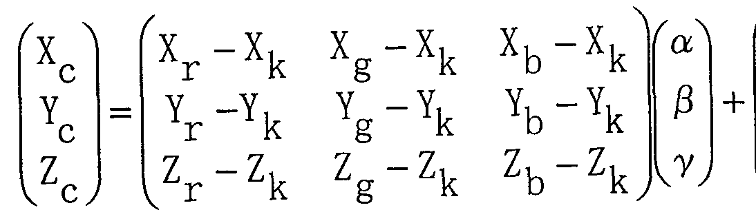
- Equation 14 In consideration of the effect of the floating black, Equation 1 is represented by Equation 14:
- Equation 14 is an equation 1 showing the XYZ tristimulus values of the color C when the effect of the black floating due to the dark current is considered. That is, the three primary colors R, G, XYZ tristimulus values X e mixed by color C are obtained these B, Y ", Z e is the three primary colors R, G, and B the dark current from each of the XY Z tristimulus values ⁇ ⁇ Tristimulus value X ⁇
- Equation 16 the emission luminances Y (R d ), Y (G d ), and Y (B d ) of each primary color alone when the effect of the black floating due to the current is taken into account are calculated by the function in Equation 2 as described above. If we consider an optical device in which f r , f g , and f b can be expressed by linear functions, this is expressed by Equation 16:
- Equation 16 is an equation for calculating the emission luminances Y (R d ), Y (G d ), and Y (B d ) of each primary color alone in consideration of the effect of floating black due to dark current.
- Equation 15 gives the emission luminances Y (R d ), Y (G d ), and Y (B d ) of each primary color alone, taking into account the black floating effect due to the dark current obtained from Equation 16
- This equation is used to calculate the scalar quantities ⁇ , ⁇ , and y (the ratio of each primary color to the maximum emission luminance) representing the light intensity from the R, G, and B digital input signals when used.
- Equation 15 is expressed by Equation 17.
- Equation 17 gives the scalar quantities ⁇ , ⁇ , and ⁇ (ratio of each primary color to the maximum emission luminance) that represent the light intensity in the case of a CRT monitor or projector where the emission luminance cannot be expressed by a linear function. This is the expression shown. Equation 15, Equation 16 and Equation 17 are for explaining ⁇ , ⁇ , and ⁇ in Equation 14. Even when the black floating phenomenon is considered, if ⁇ , ⁇ , and y are expressed by Equation 15, as shown in the description after Equation 2, the “input signal that can take a digital value of 0 to 255” By simply dividing by 255 and normalizing it, ⁇ , ⁇ , and ⁇ will be considered. ”With the concept of“ Equation 8 ”and“ Equation 9 ”, it is possible to arrive at Equation 10.
- Equation 18 is the definition of Equation 4 when considering the effect of black floating due to dark current, that is, the definition of the matrix display of the XYZ tristimulus values of the R, G, and B primary colors on the nth display.
- X nk , Y nk , and Z nk are XYZ tristimulus values when black (BK) is displayed on the nth display.
- Equation 19 is the definition of Equation 9 in consideration of the effect of black floating due to dark current, that is, the definition of the matrix display of the XYZ tristimulus values of the target colors of the R, G, and B primary colors.
- Xtk , Ytk , and Ztk are the XYZ tristimulus values of the target color black.
- XY z tristimulus values of black target color (X tk, Y tk, z tk) as the black XYZ tristimulus values of the display devices (X nk, Y nk, Z nk) in Select the XYZ tristimulus value with the largest Y nk .
- D n '— represents the inverse of matrix D n '.
- the obtained color conversion coefficient Mnt of each display device is stored in the color processing unit 8 of each display device (S52), a test image is displayed (S53), and the color calibration mode is set. finish.
- color calibration can be performed so that the target color is the target color. Further, according to this embodiment, the target color can be automatically obtained by measuring the display colors of the plurality of display devices.
- a chromaticity sensor for measuring colors of a plurality of display devices is built in the multi-vision system, and the chromaticity sensor is installed in a non-display area between the plurality of display devices.
- a color calibration device can be provided without increasing the size of the device.
- the colorimetric value having the smallest saturation among the colorimetric values of a plurality of display devices is set as the target color of the representative color, and the target color is automatically set.
- Chromatic calibration can be performed automatically in strict terms in terms of saturation, and the problem that the color reproduction area becomes narrower when simply pursuing only the common color reproduction area Solvable.
- a plurality of displays are provided for each representative color. Since the average value of the colorimetric values of the device is set as the target color of the representative color and the target color is automatically set, the color calibration can be automatically performed, and the common color reproduction area can be simply obtained. This solves the problem that the color reproduction area becomes narrower when pursuing only color.
- this embodiment can be applied to color calibration of one display device as long as the target color is determined in advance.
- the color conversion coefficient calculator 7 calculates color conversion coefficients using a three-dimensional space. That is, the color conversion coefficient calculation unit 7 calculates the color conversion coefficient using the XYZ tristimulus values of the colors obtained by mixing the three primary colors in the additive color mixture model.
- FIG. 6 is an overall block diagram of a multi-vision system having a color calibration function according to an embodiment of the present invention.
- a feature different from the first embodiment is that the chromaticity sensor 4 is installed outside the multi-vision system. Therefore, the color of the screen unit 3 itself is measured instead of the color of the light source. Further, in the first embodiment, the light leaking out of the screen is measured. However, in this system according to the second embodiment, the color at the center of the screen can be measured.
- the calibration method is the same as that of the first embodiment.
- a chromaticity sensor for measuring the colors of a plurality of display devices is installed outside the multi-vision system. The color of the display device itself can be measured instead of the color, and the position of the color measurement can be set at the center of the display device. In addition, precise color calibration becomes possible.
- FIG. 7 is an overall block diagram of a multi-vision system having a color calibration function according to an embodiment of the present invention.
- chromaticity sensors 4 smaller than the number of display devices are installed outside the multi-vision system.
- the chromaticity sensors 4 are arranged in one line on the sensor unit 10 as many as the number of display devices arranged in one horizontal row, and the sensor unit 10 is, as shown in FIG. A mechanism (not shown) that scans in the direction of A in parallel with is provided.
- Sensor unit 10
- a chromaticity sensor for measuring the colors of a plurality of display devices is installed on a one-line sensor unit outside the multi-vision system, and the sensor unit scans while parallel to the multi-vision.
- the scanning direction of the sensor is one-dimensional. Although it is only in the direction of A, two-dimensional scanning may be performed by providing a scanning mechanism parallel to the multivision and at a direction of 90 ° to the direction of A.
- the colorimetric values of all the colorimetric points are averaged and used.For example, a colorimetric point at an arbitrary position within one screen unit is determined, and the colorimetric value of only one point is determined. May be used. Alternatively, an average value of arbitrary colorimetric points may be used.
- FIG. 10 is an overall block diagram of a multi-vision system having a color calibration function according to an embodiment of the present invention.
- the feature different from the first embodiment is that the colorimetric values of the screen units 3 of the primary colors BK, R, G, and B are used when setting the target color. (XYZ tristimulus values) are displayed on the display monitor 11 connected to the system controller 6 in three-dimensional coordinates 20. The operator checks the colorimetric results of each screen unit 3 on the display monitor 11 In addition, the operator can set the target color of each primary color with a pointing device such as mouse 12.
- FIG. 11 shows two screens of the display monitor 11 connected to the system control unit 6.
- the left shows the screen before the target color is determined, and the right shows the screen after the target color is determined.
- the colorimetric results of the respective screen units are shown on the three-dimensional coordinates 20. These 3D coordinates can be rotated. Here, the colorimetric results of two screen units are displayed for simplification of the figure.
- the operator looks at the colorimetric result on the three-dimensional coordinates 20 and sets, for example, a target color so as to be the maximum common color gamut of all the screen units. If you click the R button 21 with the mouse 12, the letter R and the black dot are displayed on the three-dimensional coordinates 20. The operator can move this black spot on the three-dimensional coordinates 20 using the mouse 12.
- the rotation button 26 with the mouse 12 to rotate the coordinate system.
- the target color XYZ tristimulus values can be calculated by using the sides of the triangle formed by connecting the points of the colorimetric values of the three representative colors of each screen unit. There may be a restriction that it can only be set on vertices.
- the target color may be automatically determined without depending on the operator.
- the target is set so as to maximize the common color gamut within the color gamut of all display devices. Because the colors are set, the target color is a color that can be expressed by all display devices, and strict color calibration is possible.
- the operator since the operator checks the colorimetric results of all display devices on the connected display monitor and determines the target color, the common color reproduction of many display devices is performed. It is easy to visually set the maximum area.
- Embodiment 5 of the present invention will be described with reference to the drawings.
- FIG. 12 is an overall block diagram of a multi-vision system having a color calibration function according to an embodiment of the present invention.
- the feature that is different from the first embodiment is that, when setting the target color, if this calibration is performed for the second time or later, reference is made to the XYZ tristimulus values from the previous color measurement, If the values of the previous XYZ tristimulus value and the current XYZ tristimulus value are significantly different, execute calibration.
- FIGS. 13 and 14 are the same as FIGS. 2 and 3 except for S46.
- the determination of whether to execute the calibration in S46 is based on the calculation of the target color.
- Equation 20 is the definition of the matrix display of the XYZ tristimulus values of the R, G, and B primary colors of the previous n-th display, considering the black floating due to the ⁇ current.
- Equation 21 the matrix of the tristimulus value of the previous target color be C t , represented by Equation 21.
- Equation 21 defines the matrix display of the X, Y, and Z tristimulus values of the target color of the previous R, G, and B primary colors when the black floating due to the ⁇ current is considered. Also, the matrix Mn in consideration of the floating of black for the XYZ tristimulus values of the primary colors in this colorimetry is expressed by Equation 18 and the target color Ct is expressed by Equation 19. First, M n, was calculated _M n from current colorimetric value and the previous colorimetric values, the Re its a D Mn, represented by the formula 22.
- Equation 22 defines the difference between ⁇ ⁇ from Equation 20 obtained from the previous colorimetric result and M n from Equation 18 obtained from the current colorimetric result.
- Equation 23 is an equation indicating that the absolute value of the element of Matritas D Mn in Equation 22 is smaller than the threshold th1.
- Judgment 2 judges whether or not the condition “for all display devices, the sum of the absolute values of the elements of the matrix D Mn is calculated as the judgment parameter P 1 and it does not exceed the threshold value th 2.” .
- the expression is as shown in Expression 24.
- Equation 24 is an equation indicating that the sum of the absolute values of the elements of the matrix D Mn in Equation 22 is smaller than the threshold th2.
- the determination 3 it is determined whether or not the condition “the number of display devices that do not satisfy Expression 23 does not exceed the threshold value th3” is satisfied.
- the number of display devices that do not satisfy Expression 23 that is, the number of display devices that have changed to some extent is large, normal calibration is performed.
- the determination 4 it is determined whether or not the condition “the number of display devices that do not satisfy Expression 24 does not exceed the threshold value th4” is satisfied.
- the number of display devices that do not satisfy Expression 24 that is, the number of display devices that have changed to some extent is large, normal calibration is performed.
- C tl _M n is calculated, and it is expressed as D Cn , which is expressed by equation 25.
- Equation 25 is an equation that defines the difference between the matrix C tl (Equation 21 ) of the previous target XYZ tristimulus value of the target color and M n (Equation 18) of the current colorimetric result.
- Equation 2 6 Equation 2 6
- Equation 26 is an equation that indicates that the sum of the absolute values of the elements of Matritas D Cn in Equation 25 is smaller than the threshold th5.
- color calibration is performed for display devices other than display devices that satisfy all of Equations 23, 24 and 26 as color calibration.
- the color conversion coefficient is calculated using the previous value C t , for the target color.
- the colorimetric value of each display device and the chromaticity value of the target color are stored in the memory, and the colorimetric value obtained at the next calibration is used as the previous colorimetric value, or Compared with the chromaticity value of the target color, calibration is performed only when there is a certain degree of difference, so that unnecessary processing is not performed.
- the colorimetric value of each display device and the chromaticity value of the target color are stored in the memory, and the colorimetric value obtained at the next calibration is used for the previous measurement. Unnecessary processing because the display device with a certain difference is automatically selected by comparing it with the color value or the chromaticity value of the target color, and color calibration is performed only for the selected display device. Need not be performed.
- the related technologies include the following.
- Japanese Patent Application Laid-Open No. 63-26131327 has a similar sensor arrangement, but is considered different from the present invention in the following points.
- a target color is automatically set in order to develop a color calibration for a multi-vision including a plurality of display devices.
- the disclosure in 27 is the color adjustment of one display device.
- Japanese Unexamined Patent Publication No. Hei 4-243393 describes a colorimetric sensor, which measures the color temperature of external light and does not measure the color of the display itself. Different from the invention.
- the sensor described in Japanese Patent Application Laid-Open No. 5-236371 is a sensor for detecting a change in the brightness state around a television receiver, and a sensor for measuring the color of the display device of the present invention. And different.
- the disclosed content of Japanese Patent Application Laid-Open No. H5-2363771 is a color adjustment for a camera. Based on the results, colorimetric values are obtained and used as color correction information when printing the information. That is, colorimetry and correction of external light at the time of imaging.
- the present invention corrects the color characteristics of the display itself. Therefore, the color can be adjusted so that the outputs of a plurality of devices have the same color.
- a representative color displayed on a display device without color conversion The color conversion coefficient is calculated so that the color of the display device becomes the target color, and stored in the color processing unit, so that the color calibration can be automatically performed.
- the target color can be converted to a target color or a color close to the target color and displayed.
- the representative color is displayed without color conversion on the plurality of display devices, and the colorimetric result is obtained from the result of the color measurement.
- the color conversion coefficient is calculated so that the representative color becomes the target color and stored in the color processing unit, so that color calibration can be performed automatically, and as a result, the target that targets the colors of multiple display devices It can be converted to a color or a color close to the target color and displayed.
- the senor since the sensor is built in the multi-vision, a color calibration device can be realized without increasing the size of the device more than necessary and at no cost.
- the sensor since the sensor is installed outside the multi-vision, not the light source but the color of the display device itself can be measured, and the position of the color measurement can be set at the center of the display device. As a result, more precise color measurement and more precise color calibration are possible. Also, since the sensors are installed outside the multi-vision and can scan in parallel on the multi-vision, the colorimetry of all the display devices can be performed with fewer sensors than the number of the display devices. With this, when the number of display devices increases, colorimetry can be performed with a small number of sensors, which is effective in reducing costs.
- colorimetry can be performed by moving the colorimetric point in one display device, it is possible to correct the non-uniformity in one display device when taking the average of the colorimetric values.
- color calibration can be performed by focusing on any point.
- the target color is determined from the colorimetric results of all the display devices so as to set the largest color reproduction region in the common color reproduction region of all the display devices. Strict color calibration is possible because the target color is a color that can be expressed by all display devices.
- the target color target is determined by confirming the colorimetric results of all the display devices on the display monitor connected to the operator. It is easy to visually set the maximum area.
- a low-saturation colorimetric value is automatically set as a target target color from the colorimetric results of all the display devices. It is possible to automatically perform the rebirth, and solve the problem that the color reproduction area becomes narrow when simply searching for the common color reproduction area.
- the average value (centroid) of the colorimetric values of all the display devices is automatically calculated from the colorimetric results of all the display devices, and is set as the target color. Calibration can be performed automatically, and the problem of narrowing the color reproduction area when simply searching for the common color reproduction area is solved.
- the colorimetry results of all the display devices and the XYZ tristimulus values of the target color are stored in the memory, and are compared with the next colorimetry results, so that the calibration is required. Since it is executed only in cases, unnecessary processing need not be performed.
- the colorimetric results of all display devices are stored in the memory and compared with the colorimetric results of the next time so that only display devices that require calibration are executed, so unnecessary processing is performed. No need to do it.
Description


Claims
Priority Applications (4)
| Application Number | Priority Date | Filing Date | Title |
|---|---|---|---|
| PCT/JP1998/001709 WO1999053693A1 (fr) | 1998-04-15 | 1998-04-15 | Systeme multivision, procede d'etalonnage de couleurs et visualisation |
| EP98914018A EP0989757B1 (en) | 1998-04-15 | 1998-04-15 | Multivision system, color calibration method and display |
| JP54336799A JP3514776B2 (ja) | 1998-04-15 | 1998-04-15 | マルチビジョンシステム |
| US09/367,556 US6340976B1 (en) | 1998-04-15 | 1998-04-15 | Multivision system, color calibration method and display |
Applications Claiming Priority (1)
| Application Number | Priority Date | Filing Date | Title |
|---|---|---|---|
| PCT/JP1998/001709 WO1999053693A1 (fr) | 1998-04-15 | 1998-04-15 | Systeme multivision, procede d'etalonnage de couleurs et visualisation |
Publications (1)
| Publication Number | Publication Date |
|---|---|
| WO1999053693A1 true WO1999053693A1 (fr) | 1999-10-21 |
Family
ID=14208049
Family Applications (1)
| Application Number | Title | Priority Date | Filing Date |
|---|---|---|---|
| PCT/JP1998/001709 WO1999053693A1 (fr) | 1998-04-15 | 1998-04-15 | Systeme multivision, procede d'etalonnage de couleurs et visualisation |
Country Status (4)
| Country | Link |
|---|---|
| US (1) | US6340976B1 (ja) |
| EP (1) | EP0989757B1 (ja) |
| JP (1) | JP3514776B2 (ja) |
| WO (1) | WO1999053693A1 (ja) |
Cited By (4)
| Publication number | Priority date | Publication date | Assignee | Title |
|---|---|---|---|---|
| JP2007147852A (ja) * | 2005-11-25 | 2007-06-14 | Mitsubishi Electric Corp | マルチ画面表示装置 |
| JP2012244555A (ja) * | 2011-05-23 | 2012-12-10 | Sharp Corp | 測色位置決定方法および表示装置 |
| JP2014235295A (ja) * | 2013-05-31 | 2014-12-15 | 株式会社Jvcケンウッド | マルチプロジェクタシステム、投射装置、調整装置および画像調整方法、ならびに、画像調整プログラム |
| WO2015047103A1 (en) * | 2013-09-27 | 2015-04-02 | Phoenix Solutions As | Ultrasound mediated delivery of drugs |
Families Citing this family (77)
| Publication number | Priority date | Publication date | Assignee | Title |
|---|---|---|---|---|
| US6483537B1 (en) | 1997-05-21 | 2002-11-19 | Metavision Corporation | Apparatus and method for analyzing projected images, singly and for array projection applications |
| JP2000338950A (ja) * | 1999-05-26 | 2000-12-08 | Olympus Optical Co Ltd | 色再現システム |
| JP2001056658A (ja) * | 1999-06-07 | 2001-02-27 | Sony Corp | 陰極線管並びに輝度制御装置および方法 |
| US6760075B2 (en) | 2000-06-13 | 2004-07-06 | Panoram Technologies, Inc. | Method and apparatus for seamless integration of multiple video projectors |
| US7002606B2 (en) | 2000-07-17 | 2006-02-21 | Matsushita Electric Industrial Co., Ltd. | Image signal processing apparatus, image display apparatus, multidisplay apparatus, and chromaticity adjustment method for use in the multidisplay apparatus |
| DE60141262D1 (de) | 2000-08-31 | 2010-03-25 | Texas Instruments Inc | Automatische Farbabstimmung für verteiltes Projektionssystem |
| KR100396683B1 (ko) | 2001-01-08 | 2003-09-03 | 엘지전자 주식회사 | 티브이의 화면밝기/색도 보정장치 및 방법 |
| JP2002278537A (ja) * | 2001-03-22 | 2002-09-27 | Canon Inc | 画像処理装置、および、画像処理方法 |
| US6677958B2 (en) * | 2001-06-22 | 2004-01-13 | Eastman Kodak Company | Method for calibrating, characterizing and driving a color flat panel display |
| US7391475B2 (en) | 2002-01-31 | 2008-06-24 | Hewlett-Packard Development Company, L.P. | Display image generation with differential illumination |
| US7283181B2 (en) * | 2002-01-31 | 2007-10-16 | Hewlett-Packard Development Company, L.P. | Selectable color adjustment for image display |
| US7460179B2 (en) * | 2002-01-31 | 2008-12-02 | Hewlett-Packard Development Company, L.P. | Adaptive image display |
| FR2837056B1 (fr) * | 2002-03-07 | 2004-09-17 | France Telecom | Procede et systeme d'uniformisation du rendu colorimetrique d'une juxtaposition de surfaces d'affichage |
| KR20040013957A (ko) * | 2002-08-09 | 2004-02-14 | 엘지전자 주식회사 | 멀티비전 및 그 화면 구현 방법 |
| US7215362B2 (en) * | 2002-10-31 | 2007-05-08 | Fraunhofer-Gesellschaft Zur Foerderung Der Angewandten Forschung E.V. | Auto-calibration of multi-projector systems |
| JP4126487B2 (ja) * | 2002-11-08 | 2008-07-30 | 株式会社沖データ | 画像変換方法および画像変換装置 |
| US7184054B2 (en) * | 2003-01-21 | 2007-02-27 | Hewlett-Packard Development Company, L.P. | Correction of a projected image based on a reflected image |
| US7187797B2 (en) * | 2003-04-01 | 2007-03-06 | Applied Vision Company, Llc | Color machine vision system for colorimetry |
| US20040196250A1 (en) * | 2003-04-07 | 2004-10-07 | Rajiv Mehrotra | System and method for automatic calibration of a display device |
| TWI249959B (en) | 2003-05-16 | 2006-02-21 | Seiko Epson Corp | Image processing system, projector, information memorizing medium and image processing method |
| JP3790928B2 (ja) * | 2003-06-27 | 2006-06-28 | オリンパス株式会社 | 画像表示装置における補正データ取得方法およびキャリブレーションシステム |
| US7688316B2 (en) * | 2003-08-12 | 2010-03-30 | Apple Inc. | Adaptive method for acquiring color measurements |
| CN100533543C (zh) * | 2003-12-12 | 2009-08-26 | 松下电器产业株式会社 | 彩色图像显示装置、色变换装置、色彩模拟装置及方法 |
| US7365720B2 (en) * | 2003-12-23 | 2008-04-29 | Barco N.V. | Colour calibration of emissive display devices |
| US7948448B2 (en) | 2004-04-01 | 2011-05-24 | Polyvision Corporation | Portable presentation system and methods for use therewith |
| US7834819B2 (en) | 2004-04-01 | 2010-11-16 | Polyvision Corporation | Virtual flip chart method and apparatus |
| US7253841B2 (en) * | 2004-04-07 | 2007-08-07 | National Applied Research Laboratories | Remote control method of tile display |
| US7313270B2 (en) * | 2004-05-19 | 2007-12-25 | Applied Vision Company, Llc | Vision system and method for process monitoring |
| US7394937B2 (en) * | 2004-05-19 | 2008-07-01 | Applied Vision Company, Llc | Vision system and method for process monitoring |
| US7673995B2 (en) | 2004-07-06 | 2010-03-09 | Northrop Grumman Corporation | System and method for projector alignment |
| JP2006058754A (ja) * | 2004-08-23 | 2006-03-02 | Canon Inc | 表示装置 |
| US20060181552A1 (en) * | 2005-02-11 | 2006-08-17 | Siemens Medical Solutions Usa, Inc. | Image display calibration for ultrasound and other systems |
| TW200701179A (en) * | 2005-06-17 | 2007-01-01 | Mitac Technology Corp | Method of adjusting brightness and system using the same |
| US20070091435A1 (en) * | 2005-10-21 | 2007-04-26 | Hewlett-Packard Development Company, L.P. | Image pixel transformation |
| US8130184B2 (en) * | 2005-10-21 | 2012-03-06 | Hewlett-Packard Development Company L. P. | Image pixel transformation |
| US7609444B2 (en) * | 2005-10-21 | 2009-10-27 | Hewlett-Packard Development Company, L.P. | Projection partitioning and aligning |
| US20070091434A1 (en) * | 2005-10-21 | 2007-04-26 | Hewlett-Packard Development Company, L.P. | Luminance adjustment |
| US8248454B2 (en) * | 2007-11-14 | 2012-08-21 | Hewlett-Packard Development Company, L.P. | Video display calibration system and method |
| US20090184947A1 (en) * | 2008-01-22 | 2009-07-23 | Hupman Paul M | Color calibration system and method |
| DE102008019726A1 (de) * | 2008-04-18 | 2009-10-22 | Zentrum für Bild- und Signalverarbeitung e.V. | Verfahren und Vorrichtung zur Farbkalibrierung von Projektoren |
| JP5676430B2 (ja) * | 2008-05-02 | 2015-02-25 | トムソン ライセンシングThomson Licensing | デジタルシネマのカラーマネージメントシステム及びカラーマネージメントシステムが行う方法 |
| US8262236B2 (en) * | 2008-06-17 | 2012-09-11 | The Invention Science Fund I, Llc | Systems and methods for transmitting information associated with change of a projection surface |
| US8267526B2 (en) * | 2008-06-17 | 2012-09-18 | The Invention Science Fund I, Llc | Methods associated with receiving and transmitting information related to projection |
| US8944608B2 (en) * | 2008-06-17 | 2015-02-03 | The Invention Science Fund I, Llc | Systems and methods associated with projecting in response to conformation |
| US20100066983A1 (en) * | 2008-06-17 | 2010-03-18 | Jun Edward K Y | Methods and systems related to a projection surface |
| US8384005B2 (en) * | 2008-06-17 | 2013-02-26 | The Invention Science Fund I, Llc | Systems and methods for selectively projecting information in response to at least one specified motion associated with pressure applied to at least one projection surface |
| US8608321B2 (en) * | 2008-06-17 | 2013-12-17 | The Invention Science Fund I, Llc | Systems and methods for projecting in response to conformation |
| US8733952B2 (en) * | 2008-06-17 | 2014-05-27 | The Invention Science Fund I, Llc | Methods and systems for coordinated use of two or more user responsive projectors |
| US20090309828A1 (en) * | 2008-06-17 | 2009-12-17 | Searete Llc, A Limited Liability Corporation Of The State Of Delaware | Methods and systems for transmitting instructions associated with user parameter responsive projection |
| US8641203B2 (en) * | 2008-06-17 | 2014-02-04 | The Invention Science Fund I, Llc | Methods and systems for receiving and transmitting signals between server and projector apparatuses |
| US20100066689A1 (en) * | 2008-06-17 | 2010-03-18 | Jung Edward K Y | Devices related to projection input surfaces |
| US20090310039A1 (en) * | 2008-06-17 | 2009-12-17 | Searete Llc, A Limited Liability Corporation Of The State Of Delaware | Methods and systems for user parameter responsive projection |
| US8936367B2 (en) * | 2008-06-17 | 2015-01-20 | The Invention Science Fund I, Llc | Systems and methods associated with projecting in response to conformation |
| US8430515B2 (en) * | 2008-06-17 | 2013-04-30 | The Invention Science Fund I, Llc | Systems and methods for projecting |
| US20090310103A1 (en) * | 2008-06-17 | 2009-12-17 | Searete Llc, A Limited Liability Corporation Of The State Of Delaware | Methods and systems for receiving information associated with the coordinated use of two or more user responsive projectors |
| US8602564B2 (en) * | 2008-06-17 | 2013-12-10 | The Invention Science Fund I, Llc | Methods and systems for projecting in response to position |
| US20090313150A1 (en) * | 2008-06-17 | 2009-12-17 | Searete Llc, A Limited Liability Corporation Of The State Of Delaware | Methods associated with projection billing |
| US20110176119A1 (en) * | 2008-06-17 | 2011-07-21 | Searete Llc, A Limited Liability Corporation Of The State Of Delaware | Methods and systems for projecting in response to conformation |
| US20090310098A1 (en) * | 2008-06-17 | 2009-12-17 | Searete Llc, A Limited Liability Corporation Of The State Of Delaware | Methods and systems for projecting in response to conformation |
| US8723787B2 (en) * | 2008-06-17 | 2014-05-13 | The Invention Science Fund I, Llc | Methods and systems related to an image capture projection surface |
| US8308304B2 (en) * | 2008-06-17 | 2012-11-13 | The Invention Science Fund I, Llc | Systems associated with receiving and transmitting information related to projection |
| US20090313151A1 (en) * | 2008-06-17 | 2009-12-17 | Searete Llc, A Limited Liability Corporation Of The State Of Delaware | Methods associated with projection system billing |
| US8955984B2 (en) * | 2008-06-17 | 2015-02-17 | The Invention Science Fund I, Llc | Projection associated methods and systems |
| US20090312854A1 (en) * | 2008-06-17 | 2009-12-17 | Searete Llc, A Limited Liability Corporation Of The State Of Delaware | Methods and systems for transmitting information associated with the coordinated use of two or more user responsive projectors |
| US20090313152A1 (en) * | 2008-06-17 | 2009-12-17 | Searete Llc, A Limited Liability Corporation Of The State Of Delaware | Systems associated with projection billing |
| US20090309826A1 (en) * | 2008-06-17 | 2009-12-17 | Searete Llc, A Limited Liability Corporation Of The State Of Delaware | Systems and devices |
| CH700471B1 (de) * | 2009-02-17 | 2013-07-31 | Vario Optics Ag | Verfahren zur Herstellung einer elektro-optischen Leiterplatte mit Lichtwellenleiterstrukturen. |
| JP6011157B2 (ja) * | 2011-09-05 | 2016-10-19 | 株式会社リコー | 投影システム、投影装置、センサ装置、発電制御方法及び発電制御プログラム |
| US9076252B2 (en) | 2012-01-05 | 2015-07-07 | Qualcomm Incorporated | Image perceptual attribute adjustment |
| CN103050109B (zh) * | 2012-12-25 | 2015-04-29 | 广东威创视讯科技股份有限公司 | 多屏显示装置颜色校正方法和系统 |
| JP6240012B2 (ja) * | 2014-03-26 | 2017-11-29 | キヤノン株式会社 | 色処理装置およびその方法 |
| KR20160078023A (ko) * | 2014-12-24 | 2016-07-04 | 삼성전자주식회사 | 디스플레이 제어 장치 및 디스플레이 제어 방법 |
| CN105679263B (zh) * | 2016-02-01 | 2018-07-20 | 深圳市华星光电技术有限公司 | 用于拼接显示装置显示颜色的方法及系统 |
| US10264213B1 (en) | 2016-12-15 | 2019-04-16 | Steelcase Inc. | Content amplification system and method |
| CN111416968B (zh) | 2019-01-08 | 2022-01-11 | 精工爱普生株式会社 | 投影仪、显示系统、图像校正方法 |
| JP7363380B2 (ja) | 2019-10-31 | 2023-10-18 | セイコーエプソン株式会社 | 表示システムの制御方法および制御装置 |
| JP7338404B2 (ja) * | 2019-10-31 | 2023-09-05 | セイコーエプソン株式会社 | 表示システムの制御方法および制御装置 |
Citations (4)
| Publication number | Priority date | Publication date | Assignee | Title |
|---|---|---|---|---|
| JPH04285992A (ja) * | 1991-03-15 | 1992-10-12 | Toshiba Corp | マルチスクリーンディスプレイ装置 |
| JPH06178244A (ja) * | 1992-12-11 | 1994-06-24 | Matsushita Electric Ind Co Ltd | 投写型ディスプレイの画像処理方法およびその装置 |
| JPH07236105A (ja) * | 1994-02-25 | 1995-09-05 | Hitachi Ltd | マルチディスプレイ装置及びディスプレイ装置 |
| JPH1090645A (ja) * | 1996-09-12 | 1998-04-10 | Matsushita Electric Ind Co Ltd | 液晶表示装置 |
Family Cites Families (24)
| Publication number | Priority date | Publication date | Assignee | Title |
|---|---|---|---|---|
| US4688079A (en) * | 1986-08-05 | 1987-08-18 | Zenith Electronics Corporation | Color CRT purity measurement |
| JPS63261327A (ja) | 1987-04-20 | 1988-10-28 | Sony Corp | カラ−液晶表示装置 |
| US4962418A (en) | 1987-06-30 | 1990-10-09 | Kabushiki Kaisha Toshiba | Color picture display apparatus |
| US4875032A (en) | 1987-10-26 | 1989-10-17 | Mcmanus Paul A | Method and apparatus for processing colorimetric parameters of a color sample |
| US5136390A (en) * | 1990-11-05 | 1992-08-04 | Metavision Corporation | Adjustable multiple image display smoothing method and apparatus |
| JPH04243393A (ja) | 1991-01-18 | 1992-08-31 | Mitsubishi Electric Corp | 映像表示機器の映像制御回路 |
| JP2567756B2 (ja) | 1991-07-04 | 1996-12-25 | 三洋電機株式会社 | テレビジョン受信機の画像自動制御表示装置 |
| US5249056A (en) * | 1991-07-16 | 1993-09-28 | Sony Corporation Of America | Apparatus for generating video signals from film |
| JP3126046B2 (ja) | 1991-10-28 | 2001-01-22 | 富士通株式会社 | カラー画像の色調整方法及び色調整装置 |
| JPH05127620A (ja) * | 1991-11-06 | 1993-05-25 | Matsushita Electric Ind Co Ltd | 液晶投写型カラーデイスプレイの調整方法および調整回路 |
| JP3116472B2 (ja) | 1991-11-18 | 2000-12-11 | ソニー株式会社 | ホワイト・バランス調整方法 |
| US5321494A (en) * | 1992-03-23 | 1994-06-14 | Eastman Kodak Company | Subtractive measurement method and apparatus for CRT output intensity measurement |
| US5270818A (en) * | 1992-09-17 | 1993-12-14 | Alliedsignal Inc. | Arrangement for automatically controlling brightness of cockpit displays |
| KR0134160B1 (ko) | 1993-03-17 | 1998-04-22 | 모리시타 요이찌 | 화상보정장치 |
| JPH06311428A (ja) | 1993-04-21 | 1994-11-04 | Fujitsu General Ltd | 多画面表示システム |
| JPH0772817A (ja) | 1993-06-29 | 1995-03-17 | Hitachi Ltd | マルチビジョンの輝度制御装置 |
| JP3089924B2 (ja) | 1993-12-27 | 2000-09-18 | ブラザー工業株式会社 | Crtキャリブレーション装置 |
| US5510851A (en) | 1994-03-29 | 1996-04-23 | Radius Inc. | Method and apparatus for dynamic purity correction |
| JPH07301844A (ja) | 1994-05-09 | 1995-11-14 | Olympus Optical Co Ltd | カメラ |
| US5499040A (en) * | 1994-06-27 | 1996-03-12 | Radius Inc. | Method and apparatus for display calibration and control |
| JPH08336055A (ja) | 1995-06-08 | 1996-12-17 | Ricoh Co Ltd | 画像処理装置 |
| JP2914227B2 (ja) | 1995-07-11 | 1999-06-28 | 富士ゼロックス株式会社 | 画像処理装置および画像処理方法 |
| US5612710A (en) * | 1995-08-22 | 1997-03-18 | Fairtron Corporation | Real time low cost, large scale array 65K color display using lamps |
| US6262710B1 (en) * | 1999-05-25 | 2001-07-17 | Intel Corporation | Performing color conversion in extended color polymer displays |
-
1998
- 1998-04-15 EP EP98914018A patent/EP0989757B1/en not_active Expired - Lifetime
- 1998-04-15 WO PCT/JP1998/001709 patent/WO1999053693A1/ja active Application Filing
- 1998-04-15 JP JP54336799A patent/JP3514776B2/ja not_active Expired - Fee Related
- 1998-04-15 US US09/367,556 patent/US6340976B1/en not_active Expired - Fee Related
Patent Citations (4)
| Publication number | Priority date | Publication date | Assignee | Title |
|---|---|---|---|---|
| JPH04285992A (ja) * | 1991-03-15 | 1992-10-12 | Toshiba Corp | マルチスクリーンディスプレイ装置 |
| JPH06178244A (ja) * | 1992-12-11 | 1994-06-24 | Matsushita Electric Ind Co Ltd | 投写型ディスプレイの画像処理方法およびその装置 |
| JPH07236105A (ja) * | 1994-02-25 | 1995-09-05 | Hitachi Ltd | マルチディスプレイ装置及びディスプレイ装置 |
| JPH1090645A (ja) * | 1996-09-12 | 1998-04-10 | Matsushita Electric Ind Co Ltd | 液晶表示装置 |
Non-Patent Citations (1)
| Title |
|---|
| See also references of EP0989757A4 * |
Cited By (4)
| Publication number | Priority date | Publication date | Assignee | Title |
|---|---|---|---|---|
| JP2007147852A (ja) * | 2005-11-25 | 2007-06-14 | Mitsubishi Electric Corp | マルチ画面表示装置 |
| JP2012244555A (ja) * | 2011-05-23 | 2012-12-10 | Sharp Corp | 測色位置決定方法および表示装置 |
| JP2014235295A (ja) * | 2013-05-31 | 2014-12-15 | 株式会社Jvcケンウッド | マルチプロジェクタシステム、投射装置、調整装置および画像調整方法、ならびに、画像調整プログラム |
| WO2015047103A1 (en) * | 2013-09-27 | 2015-04-02 | Phoenix Solutions As | Ultrasound mediated delivery of drugs |
Also Published As
| Publication number | Publication date |
|---|---|
| JP3514776B2 (ja) | 2004-03-31 |
| EP0989757A1 (en) | 2000-03-29 |
| EP0989757A4 (en) | 2000-03-29 |
| EP0989757B1 (en) | 2011-12-07 |
| US6340976B1 (en) | 2002-01-22 |
Similar Documents
| Publication | Publication Date | Title |
|---|---|---|
| WO1999053693A1 (fr) | Systeme multivision, procede d'etalonnage de couleurs et visualisation | |
| Berns et al. | CRT colorimetry. Part I: Theory and practice | |
| KR100858985B1 (ko) | 광함수생성장치를 이용한 씸레스 타일 디스플레이 전자 교정 방법 및 씸레스 타일 디스플레이 시스템 | |
| US7314283B2 (en) | Color correction method and device for projector | |
| EP1463338B1 (en) | System, method and software for processing a projected image | |
| US7852316B2 (en) | Image processing method of pointer input system | |
| EP1205902B1 (en) | Image display system, image processing method, and information storage medium | |
| EP1391870B1 (en) | Image display system, projector, information storage medium and image processing method | |
| US8243210B2 (en) | Apparatus and method for ambient light adaptive color correction | |
| US6542185B1 (en) | Method and apparatus for automated optimization of white and color balance on video camera | |
| US7024034B2 (en) | Color temperature conversion system and method using the same | |
| US20070110304A1 (en) | Projector color correcting method | |
| JPH05127620A (ja) | 液晶投写型カラーデイスプレイの調整方法および調整回路 | |
| US20110148902A1 (en) | Evaluation method of display device | |
| CN101151886A (zh) | 图像显示装置及图像显示方法 | |
| KR20200074645A (ko) | 디스플레이장치 및 그 제어방법 | |
| JP4145888B2 (ja) | 表示装置および表示方法 | |
| JP2021101204A (ja) | 制御装置の動作方法、プロジェクターの制御方法およびプロジェクター | |
| US20140314317A1 (en) | Method and apparatus for converting gray level of color image | |
| Hardeberg et al. | Colorimetric characterization of projection displays using a digital colorimetric camera | |
| KR20180062571A (ko) | 표시 패널의 보상 데이터 생성 방법 및 장치 | |
| WO2019097937A1 (ja) | 画像処理装置、画像処理方法、及びプログラム、並びに画像形成装置 | |
| JP5058532B2 (ja) | 画像表示システムおよび画像表示方法 | |
| JP2012248911A (ja) | 画像表示装置 | |
| KR20070012017A (ko) | 디스플레이 기기의 특정 색보정 방법 및 이의 장치 |
Legal Events
| Date | Code | Title | Description |
|---|---|---|---|
| WWE | Wipo information: entry into national phase |
Ref document number: 09367556 Country of ref document: US |
|
| AK | Designated states |
Kind code of ref document: A1 Designated state(s): JP US |
|
| AL | Designated countries for regional patents |
Kind code of ref document: A1 Designated state(s): AT BE CH CY DE DK ES FI FR GB GR IE IT LU MC NL PT SE |
|
| WWE | Wipo information: entry into national phase |
Ref document number: 1998914018 Country of ref document: EP |
|
| 121 | Ep: the epo has been informed by wipo that ep was designated in this application | ||
| WWP | Wipo information: published in national office |
Ref document number: 1998914018 Country of ref document: EP |