EP1205902B1 - Image display system, image processing method, and information storage medium - Google Patents
Image display system, image processing method, and information storage medium Download PDFInfo
- Publication number
- EP1205902B1 EP1205902B1 EP01126883A EP01126883A EP1205902B1 EP 1205902 B1 EP1205902 B1 EP 1205902B1 EP 01126883 A EP01126883 A EP 01126883A EP 01126883 A EP01126883 A EP 01126883A EP 1205902 B1 EP1205902 B1 EP 1205902B1
- Authority
- EP
- European Patent Office
- Prior art keywords
- color gamut
- image
- target
- displayable
- display
- Prior art date
- Legal status (The legal status is an assumption and is not a legal conclusion. Google has not performed a legal analysis and makes no representation as to the accuracy of the status listed.)
- Expired - Lifetime
Links
- 238000003672 processing method Methods 0.000 title claims description 7
- 238000006243 chemical reaction Methods 0.000 claims description 89
- 239000011159 matrix material Substances 0.000 claims description 72
- 238000000034 method Methods 0.000 claims description 30
- 230000000007 visual effect Effects 0.000 claims description 28
- 230000007613 environmental effect Effects 0.000 claims description 18
- 238000001514 detection method Methods 0.000 claims description 5
- 239000003086 colorant Substances 0.000 description 26
- 238000013507 mapping Methods 0.000 description 24
- 238000010586 diagram Methods 0.000 description 14
- 238000012545 processing Methods 0.000 description 11
- 239000004973 liquid crystal related substance Substances 0.000 description 6
- 230000007274 generation of a signal involved in cell-cell signaling Effects 0.000 description 5
- 238000012986 modification Methods 0.000 description 5
- 230000004048 modification Effects 0.000 description 5
- 230000005540 biological transmission Effects 0.000 description 2
- 238000005401 electroluminescence Methods 0.000 description 2
- 241001085205 Prenanthella exigua Species 0.000 description 1
- 230000006835 compression Effects 0.000 description 1
- 238000007906 compression Methods 0.000 description 1
- 230000001419 dependent effect Effects 0.000 description 1
- 238000013461 design Methods 0.000 description 1
- 230000000694 effects Effects 0.000 description 1
- 238000002474 experimental method Methods 0.000 description 1
- 238000003384 imaging method Methods 0.000 description 1
- 238000012546 transfer Methods 0.000 description 1
Images


Classifications
-
- G—PHYSICS
- G09—EDUCATION; CRYPTOGRAPHY; DISPLAY; ADVERTISING; SEALS
- G09G—ARRANGEMENTS OR CIRCUITS FOR CONTROL OF INDICATING DEVICES USING STATIC MEANS TO PRESENT VARIABLE INFORMATION
- G09G1/00—Control arrangements or circuits, of interest only in connection with cathode-ray tube indicators; General aspects or details, e.g. selection emphasis on particular characters, dashed line or dotted line generation; Preprocessing of data
- G09G1/28—Control arrangements or circuits, of interest only in connection with cathode-ray tube indicators; General aspects or details, e.g. selection emphasis on particular characters, dashed line or dotted line generation; Preprocessing of data using colour tubes
- G09G1/285—Interfacing with colour displays, e.g. TV receiver
-
- H—ELECTRICITY
- H04—ELECTRIC COMMUNICATION TECHNIQUE
- H04N—PICTORIAL COMMUNICATION, e.g. TELEVISION
- H04N9/00—Details of colour television systems
- H04N9/64—Circuits for processing colour signals
- H04N9/67—Circuits for processing colour signals for matrixing
-
- H—ELECTRICITY
- H04—ELECTRIC COMMUNICATION TECHNIQUE
- H04N—PICTORIAL COMMUNICATION, e.g. TELEVISION
- H04N9/00—Details of colour television systems
- H04N9/64—Circuits for processing colour signals
- H04N9/73—Colour balance circuits, e.g. white balance circuits or colour temperature control
-
- G—PHYSICS
- G09—EDUCATION; CRYPTOGRAPHY; DISPLAY; ADVERTISING; SEALS
- G09G—ARRANGEMENTS OR CIRCUITS FOR CONTROL OF INDICATING DEVICES USING STATIC MEANS TO PRESENT VARIABLE INFORMATION
- G09G2320/00—Control of display operating conditions
- G09G2320/06—Adjustment of display parameters
- G09G2320/0666—Adjustment of display parameters for control of colour parameters, e.g. colour temperature
Definitions
- the present invention relates to an image display system, image processing method, and information storage medium.
- CMS color management system
- the desired image view can differ, depending on individuals and location.
- the standardized method for displaying images in Japan is NTSC, whereas one of the standardized methods for displaying images in Europe is PAL.
- image information that is generated in real time must be converted in real time.
- EP-A-1 079 605 discloses a color reproduction system that accurately corrects color displayed on a user's own display by generating a profile at a server, in order to allow each user to obtain a service for performing accurate color reproduction through a network.
- This system includes a network connecting section for connecting a color reproduction terminal to a network; a color image display for displaying a color image; a color camera or a sensor for capturing a color reproduction characteristic of the color image display and a viewing illuminant condition; and a color converting section that provides color conversion for the color image obtained through the network and outputs it to the color image display.
- US-A-6,320,980 a family member of Japanese patent publication JP 09-098301, discloses an image processing method and apparatus for obtaining a conversion parameter to be used for a signal conversion process between body color image data and light source color image data, the method comprising the steps of calculating a conversion parameter to match color sight between a body color and a light source color with each other, for each of a plurality of representative colors and calculating the conversion parameter to be used for the signal conversion process, on the basis of the plurality of conversion parameters for each of the plurality of representative colors, whereby a conversion coefficient applicable to an entire image can be obtained, and the signal conversion process between the body color and the light source color can be performed well without being affected by any characteristic of device.
- the conversion parameters are obtained from a color matching experiment performed for each of calculation of said representative colors and are stored in a look-up table.
- US-A-6,320,980 describes an arrangement comprising a scanner, a first conversion unit for converting RGB color data obtained from the scanner to tristimulus XYZ color data, a second unspecified conversion unit for converting the XYZ color data based on detected ambient light information to converted XYZ color data, a third conversion unit for converting the converted XYZ color data to RGB color data, and a monitor for displaying an image based on the RGB color data obtained from the third conversion unit.
- the first conversion unit operates on the basis of a scanner profile and the the third conversion unit operates on the basis of a monitor profile.
- the present invention was devised in the light of the above-described technical problems and has as an objective thereof the provision of an image display system, image processing method, and information storage medium that enable faster reproduction of an optimal image view in accordance with an image characteristic selected by a user.
- the present invention enables conversions that are faster than a case in which a look-up table (hereinafter abbreviated to LUT) is used as conversion information, by generating a conversion matrix for use as conversion information and using that conversion matrix in the conversion of the image information, which also enables a reduction in the dedicated space within a storage region.
- LUT look-up table
- a calibration image is generated within the projection-type display device, it is possible for the projection-type display device itself to perform calibration, without having to input a calibration image from an external input device such as a PC to the projection-type display device.
- TV standard such as NTSC, PAL, or SECAM will also be referred to as “image display method”
- color signal type such as RGB or sRGB will also be referred to as “image classification” hereinafter.
- the relationship between a color gamut based on an image characteristic and a color gamut that can be displayed by the image display means depends on the visual environment and the image characteristic. For that reason, it is not possible to reproduce an image appropriately by a method of converting image information that uses only a single conversion matrix.
- a preferred embodiment of present invention make it possible to reproduce an image more appropriately by dividing the relationships into the four patterns and generating a conversion matrix in correspondence to each of those patterns.
- a preferred embodiment makes it possible to reproduce an image more appropriately, by generating a conversion matrix that emphasizes either hue reproducibility or color gamut reproducibility.
- Embodiments of the present invention applied to an image display system that uses a liquid crystal projector are described below by way of example, with reference to the accompanying figures. Note that the embodiments described below do not limit the scope of the invention defined by the claims laid out herein. Similarly, the overall configuration of the embodiments below should not be taken as limiting the subject matter defined by the claims herein.
- FIG. 1 A schematic illustrative view of an image display system in accordance with one embodiment of the present invention is shown in Fig. 1.
- a projector 20 which is one type of a projection-type display device provided substantially facing a screen 10, projects an image for a predetermined presentation.
- a presenter 30 gives a presentation to an audience, while using a light spot 70 projected from the laser pointer 50 to point at a desired position of an image in an image display region 12, which is a display-receiving area on the screen.
- the image view on the image display region 12 will vary greatly, depending on factors such as the type of the screen 10 and ambient light 80.
- the type of the screen 10 could make it seem to be white with a yellow cast or white with a blue cast.
- differences in the ambient light 80 could make the same white appear to be a bright white or a dull white.
- this projector 20 has become smaller and easy to transport. For that reason, it has become possible to perform presentations at a client's location, by way of example, but it is difficult to adjust colors to match the environment at the client's location and the manual adjustment of colors at the client's location takes too much time.
- color modification is based on an input-output profile that indicates input-output characteristics that are specific to that particular projector, so no consideration is paid to the visual environment in which the image is projected and displayed. Note that this "profile” means “characteristic data”.
- the view of colors is determined by three factors: light, the reflection or transmission of light by objects, and vision.
- This embodiment of the present invention implements an image display system that can reproduce appropriate colors, by detecting the visual environment of light and the reflection or transmission of light by objects.
- the projector 20 is to be used in Japan, for example, it is considered that the user would want to reproduce the colors of the image in accordance with the NTSC method, whereas if the projector 20 is to be used in Europe, it is considered that the user might want to reproduce the colors of the image in accordance with the PAL method.
- the projector 20 is configured in such a manner that the colors of images can be adjusted on the basis of a selection of the user's image display method or the like.
- the device is provided with a colored-light sensor 60 that functions as visual environment detection means for detecting the visual environment, as shown in Fig. 1, and environmental information from the colored-light sensor 60 is input to the projector 20.
- the colored-light sensor 60 measures environmental information (more specifically, RGB or XYZ tristimulus values) within the image display region 12 of the screen 10.
- the projector 20 is provided with a conversion means for generating a matrix used for conversion, based on selection information such as environmental information from the colored-light sensor 60 and the user's image display method, then using that conversion matrix for converting image information to be used for the image display.
- An image display system that enables appropriate image color reproduction can be implemented by detecting the visual environment on the basis of environmental information and determining the user preferences from selection information.
- this embodiment calculates the displayable color gamut that can be displayed by the projector 20 in the visual environment in which the presentation is given, and also uses an image display method selected by the user to calculate a target color gamut. Image processing is done by comparing the thus-obtained displayable color gamut and target color gamut, so that the colors that are as close as possible to the target color gamut can be displayed by the projector 20.
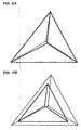
- FIG. 2A A schematic diagram of a target color gamut and a displayable color gamut when the target color gamut and the displayable color gamut match is shown in Fig. 2A and a schematic diagram of a target color gamut and a displayable color gamut when the displayable color gamut is larger than the target color gamut is shown in Fig. 2B.
- a schematic diagram of a target color gamut and a displayable color gamut when the displayable color gamut is smaller than the target color gamut is shown in Fig. 3A
- a schematic diagram of a target color gamut and a displayable color gamut when the target color gamut has a portion that overlaps the displayable color gamut and a portion that does not overlap the displayable color gamut is shown in Fig. 3B.
- the solid lines denote target color gamuts and the broken lines denote displayable color gamuts.
- the intersection of lines from each vertex of each triangular color gamut towards the central portion of the triangular shape is the white spot.
- the relationship between the target color gamut and the displayable color gamut is not fixed. It can be broadly classified into the four patterns shown in Figs. 2A to 3B.
- the method of converting image information differs somewhat depending on which of these four patterns is appropriate. For example, if the displayable color gamut covers the whole of the target color gamut, as shown in Figs. 2A and 2B, the target image can be reproduced appropriately by using an ordinary conversion method.
- the displayable color gamut does not cover the entire target color gamut, as shown in Figs. 3A and 3B, it will not be possible to reproduce the target image appropriately by using an ordinary conversion method.
- color gamut mapping this could also be called color gamut compression
- This embodiment of the present invention uses either a method that places priority on color gamuts or a method that places priority on hues, as the color gamut mapping method.
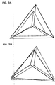
- FIG. 4A A schematic diagram of color gamuts (mapping color gamuts) after color gamut mapping that places priority on color gamuts is shown in Fig. 4A and a schematic diagram of color gamuts after color gamut mapping that places priority on hues is shown in Fig. 4B.
- Figs. 4A and 4B broken lines denote displayable color gamuts and dot-dot-dash lines denote target color gamuts.
- Figs. 4A and 4B show examples in which the target color gamut and displayable color gamut of Fig. 3B overlap partially.
- a vertex D of the target color gamut is within the displayable color gamut ABC but a vertex E and a vertex F of the target color gamut is on the outside of the displayable color gamut ABC. It is therefore not possible to reproduce colors in the vicinity of the vertex E and the vertex F.
- color gamut mapping is performed to ensure that those colors are reproduced as close as possible.
- the color gamut mapping places priority on either color gamut or hue.
- a point H that is close as possible to the vertex E and a point I that is close as possible to the vertex F are obtained from intersections between the triangular shape DEF and the triangular shape ABC. Note that since the vertex D is within the triangular shape ABC, it can be used without modification as a vertex G of the new color gamut.
- the triangular shape GHI obtained in this manner is the mapping color gamut obtained when priority is on color gamut, in other words, that obtained when consideration is placed on making the mapping color gamut as extensive as possible.
- the priority is on hue, for example, points K and L where lines from the vertices of the triangular shape DEF towards the white spot intersect the edges of the triangular shape ABC. Note that since the vertex D is within the triangular shape ABC, it can be used without modification as a vertex J of the new color gamut.
- the triangular shape JKL obtained in this manner is the mapping color gamut obtained when priority is on hue, in other words, that obtained when consideration is placed on reproducing the hues as accurately as possible.
- Color has three attributes : brightness, chroma, and hue. Of these three, human eyes are most sensitive to hue. It is therefore possible to use the projector 20 to reproduce colors that are closer to the target color gamut, by obtaining a mapping color gamut that places priority on hue.
- mapping color gamuts of Figs. 2A and 2B can use the target color gamut without modification.
- This embodiment of the invention generates a conversion matrix for the conversion of image information that enables the reproduction of the mapping color gamut as described above, then used the thus-generated conversion matrix to convert the image information.
- FIG. 5 A functional block diagram of an image processor section 100 within the projector 20 in accordance with one embodiment of the invention is shown in Fig. 5.
- the projector 20 inputs an R1 signal, a G1 signal, and a B1 signal (which form an RGB signal in analog form, sent from a PC or the like) to an A/D converter section 110, and uses the projector image processor section 100 to perform color conversion on an R2 signal, a G2 signal, and a B2 signal which have been converted into digital form by a CPU 200.
- An R3 signal, a G3 signal, and a B3 signal that have been subjected to the color conversion are input to a D/A converter section 180, and an R4 signal, a G4 signal, and a B4 signal that have been converted into analog form are input to a light valve (L/V) drive section 190 that is part of the image display means, to drive liquid crystal light bulbs to display an image.
- L/V light valve
- the projector image processor section 100 comprises a projector color converter section 120, a color gamut calculation section 160, and a calibration signal generation section 150.
- the color gamut calculation section 160 comprises a target profile storage section 162 and a projector profile storage section 164.
- the calibration signal generation section 150 generates calibration image signals. These calibration image signals are input to the projector color converter section 120 as a digital-format R2 signal, G2 signal, and B2 signal, in a similar manner to the signals output from the A/D converter section 110.
- calibration image signals are generated within the projector 20 in this manner, calibration can be done by the projector 20 itself, without having to input calibration image signals to the projector 20 from an external input device such as a PC.
- the projector color converter section 120 references a projector profile that is managed by the projector profile storage section 164 to convert the RGB signals (R2 signal, G2 signal, and B2 signal) from the calibration signal generation section 150 into digital RGB signals (R3 signal, G3 signal, and B3 signal) suitable for projector output.
- the projector color converter section 120 comprises a matrix generation section 122, which generates a conversion matrix for the conversion of the digital signals (R2 signal, G2 signal, and B2 signal) that are image information, and a matrix converter section 124, which uses the thus-generated conversion matrix to convert the image information.
- the matrix generation section 122 generates a matrix for use in conversion, enabling reproduction of the mapping color gamut calculated by the color gamut calculation section 160.
- the color gamut calculation section 160 comprises the target profile storage section 162 and the projector profile storage section 164. More specifically, the color gamut calculation section 160 calculates the mapping color gamut that was described with reference to Figs. 2 to 4, in such a manner as to obtain the preferred colors selected by the user and also the view of image colors that conforms to the visual environment, based on a target profile selected by the user, environmental information from the colored-light sensor 60, and a projector profile.
- each target profile is a type of input-output characteristic data for the colors that will be the target. More specifically, each target profile is data that defines correspondences between factors such as RGB luminance signals and tristimulus values (X, Y, Z), by way of example. With this embodiment of the invention, each target profile is implemented by a matrix that converts RGB luminance signals into tristimulus values (X, Y, Z). A plurality of profiles corresponding to a plurality of image characteristics that can be selected by the user is provided as target profiles.
- a "projector profile” is a type of input-output characteristic data corresponding to the type of the projector 20. More specifically, each projector profile is data that defines correspondences between factors such as RGB luminance signals and tristimulus values (X, Y, Z) obtained in practice when an image is displayed in an ideal environment on the basis of those RGB luminance signals, by way of example. With this embodiment of the invention, each projector profile is implemented by a matrix that converts RGB luminance signals into tristimulus values (X, Y, Z).
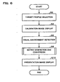
- FIG. 6 A flowchart of the procedure for image processing in accordance with one embodiment of the invention is shown in Fig. 6.
- the user of the projector 20 selects one image characteristic from a plurality of image characteristics allocated to operating buttons of the projector 20. More specifically, the outer surface of the projector 20 is provided with selection buttons for image characteristics such as NTSC, PAL, or SECAM, and the user is induced to press one of those selection buttons to select one image characteristic.
- image characteristics such as NTSC, PAL, or SECAM
- This selection information is sent to the projector image processor section 100.
- the projector image processor section 100 turns on the flag of the thus-selected target profile, from a plurality of target profiles of the target profile storage section 162, based on that selection information.
- the projector image processor section 100 selects the target profile corresponding to the user's selection (step S2).
- the projector 20 After the target profile corresponding to the user's selection has been selected, the projector 20 generates calibration signals (R2, G2, B2) from the calibration signal generation section 150.
- the calibration signal generation section 150 outputs those calibration signals to the projector color converter section 120.
- the projector color converter section 120 uses a default (initial state) conversion matrix to convert the calibration signals and outputs them as digital RGB signals (R3, G3, B3).
- the D/A converter section 180 converts the digital RGB signals into analog RGB signals (R4, G4, B4).
- the L/V drive section 190 drives liquid crystal light valves, based on the analog RGB signals (R4, G4, B4).
- the projector 20 projects a calibration image to display on the image display region 12
- the colored-light sensor 60 detects tristimulus values for detecting the visual environment
- the visual environment can be detected more appropriately, by using the calibration image in the detection of the visual environment. It is therefore possible to reproduce the image view more appropriately.
- the projector color converter section 120 generates a conversion matrix based on the thus-detected visual environment, then uses that conversion matrix to convert the image information (step S8).
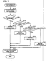
- FIG. 7 A flowchart of the procedure of matrix generation and conversion processing in accordance with one embodiment of the present invention is shown in Fig. 7.
- the color gamut calculation section 160 calculates and obtains the target color gamut, based on the target profile selected from the target profile storage section 162.
- the color gamut calculation section 160 then calculates and obtains the displayable color gamut of the projector 20, based on the projector profile stored in the projector profile storage section 164 and the tristimulus values detected by the colored-light sensor 60 (step S12).
- the color gamut calculation section 160 compares the displayable color gamut and the target color gamut obtained by the calculations (step S12).
- the matrix generation section 122 generates a conversion matrix that enables reproduction of the triangular mapping color gamut denoted by the solid line in Fig. 2A (step S16).
- the matrix generation section 122 If the displayable color gamut is larger than the target color gamut, in other words, if the situation is as shown in Fig. 2B (step S18), the matrix generation section 122 generates a conversion matrix that enables reproduction of the triangular mapping color gamut denoted by the solid line in Fig. 2B (step S20).
- the matrix generation section 122 If the displayable color gamut is smaller than the target color gamut, in other words, if the situation is as shown in Fig. 3A, the matrix generation section 122 generates a conversion matrix that enables reproduction of a mapping color gamut that gives priority to either color gamut or hue reproduction, as shown in Fig. 4A or 4B (step S24).
- the displayable color gamut has a portion that overlaps the target color gamut and a portion that does not overlap, as shown in Fig. 3B.
- the matrix generation section 122 generates a conversion matrix that enables reproduction of a mapping color gamut that gives priority to either color gamut or hue reproduction, as shown in Fig. 4A or 4B (step S26).
- the matrix converter section 124 uses the conversion matrix generated by the matrix generation section 122 to perform color conversion (image information conversion) (step S28). More specifically, the matrix converter section 124 uses a 3x3 conversion matrix to convert the digital RGB signals (R2, G2, B2) and outputs them as digital RGB signals (R3, G3, B3).
- the projector 20 uses the D/A converter section 180 to convert the thus-converted digital RGB signals (R3, G3, B3) into analog form, then uses the converted analog RGB signals (R4, G4, B4) to display the actual presentation image (step S10).
- this embodiment uses a conversion matrix to convert image information to enable the display of an image that conforms to the image characteristic selected by the user.
- This embodiment also projects and displays an image from consideration of the visual environment, by using the colored-light sensor 60 to detect the visual environment.
- this embodiment makes it possible to convert the image information more rapidly and reduce the amount of dedicated storage required therefor, by using a conversion matrix for the image information conversion, not an LUT.
- This embodiment also divides the relationship between displayable color gamut and target color gamut into four patterns during the generation of the conversion matrix, and generates a conversion matrix corresponding to the appropriate pattern.
- the relationship between the displayable color gamut and the target color gamut differs with the environment in which the projector 20 is used and the image characteristic selected by the user. For that reason, it is necessary to generate a conversion matrix that is appropriate for the relationship between the displayable color gamut and the target color gamut.
- an appropriate conversion matrix can be generated by generating a conversion matrix corresponding to any of four assumed patterns.
- the target color gamut can be used substantially unchanged as the mapping color gamut, enabling faster conversion matrix generation than in the cases shown in Figs. 3A and 3B in which color gamut mapping is necessary.
- the A/D converter section 110 could be implemented by an A/D converter or the like, the D/A converter section 180 by a D/A converter or the like, the L/V drive section 190 by a liquid crystal light valve driver or the like, the projector color converter section 120 by image processing circuitry or an ASIC, and the color gamut calculation section 160 by a CPU and RAM, by way of example.
- these portions could be implemented in a hardware fashion by circuitry, or they could be implemented in a software fashion by drivers and/or programs.
- the functions of the components shown in Fig. 5 could be implemented by reading out a program from an information storage medium 300.
- the information storage medium 300 could be a CD-ROM, DVD-ROM, ROM, RAM, or HDD, by way of example, and the method of reading the program therefrom could be a direct method or an indirect method.
- components such as a color filter and photodiode that selectively pass each stimulus value, an A/D converter that converts an analog signal from that photodiode into a digital signal, and an op-amp that amplifies that digital signal could be employed therefor.
- an image characteristic such as RGB or sRGB image type could be employed as the target profile, instead of the NTSC or similar image display method.
- the visual environment detection means could be imaging means such as a CCD camera or a CMOS camera, instead of the colored-light sensor 60.
- the abovementioned screen 10 could be of a reflective type or a transmissive type.
- the conversion matrix that was described above related to a single matrix, but the color conversion could also be done with a combination of a plurality of matrices.
- the color conversion could be done with a combination of an inverse-conversion matrix corresponding to an output device and an environment compensation matrix that reflects environmental information.
- the present invention can also be applied to presentations in which images are displayed by a display means other than a projection-type image display device such as a projector.
- this display means could be a display device such as a cathode ray tube (CRT), a plasma display panel (PDP), a field emission device (FED), and electro-luminescence (EL) device, or a direct-view type of liquid crystal display device, or a projector using a digital micromirror device (DMD), by way of example.
- the DMD is a tradename registered by Texas Instruments Inc., of the US.
- the projector is not limited to a front-projection type; it could equally well be of a rear-projection type.
- this invention is also effective when used in the display of images, such as those at meetings, during medical treatment, in the design and fashion fields, business activities, commercials, and education, as well as general-purpose images such as those in movies, TV, videos, and games.
- the functions of the above-described projector image processor section 100 of the projector 20 could be implemented by a simple image display device (such as the projector 20 itself) or by distribution between a plurality of processing devices (such as distributed processing between the projector 20 and a PC).
Landscapes
- Engineering & Computer Science (AREA)
- Signal Processing (AREA)
- Multimedia (AREA)
- Theoretical Computer Science (AREA)
- Computer Hardware Design (AREA)
- General Physics & Mathematics (AREA)
- Physics & Mathematics (AREA)
- Remote Sensing (AREA)
- Radar, Positioning & Navigation (AREA)
- Controls And Circuits For Display Device (AREA)
- Processing Of Color Television Signals (AREA)
- Color Image Communication Systems (AREA)
- Control Of Indicators Other Than Cathode Ray Tubes (AREA)
- Digital Computer Display Output (AREA)
Description
- Japanese Patent No. 2000-344822, filed on November 13, 2000, and Japanese Patent No. 2000-296027, filed on September 27, 2001, are herein incorporated by reference in their entirety.
- The present invention relates to an image display system, image processing method, and information storage medium.
- Various color conversion systems such as the color management system (CMS) have been proposed in order to provide uniformity in an image view.
- However, the desired image view can differ, depending on individuals and location.
- As one example, the standardized method for displaying images in Japan is NTSC, whereas one of the standardized methods for displaying images in Europe is PAL.
- A situation that can therefore arise in which an image that was generated on the assumption that it would be viewed as NTSC in Japan is displayed in Europe to Europeans, giving rise to a difference in which the image is viewed, from consideration of the preferences of Europeans.
- For that reason, it is not sufficient merely to convert the image information (such as the RGB signals), but it is necessary to convert the image information in accordance with an image characteristic such as the display method selected by the user.
- Since an image view is also affected by factors such as ambient light, it is also necessary to detect the visual environment and take that visual environment into consideration when converting the image information.
- During the conversion of image information in accordance with the image characteristic and the visual environment, the information used for the conversion must be generated. However, storing conversion information for all assumed image characteristics and visual environments beforehand in a storage region places pressures upon that storage region.
- In addition, image information that is generated in real time must be converted in real time.
- EP-A-1 079 605 (prior art according to Article 54(3) EPC) discloses a color reproduction system that accurately corrects color displayed on a user's own display by generating a profile at a server, in order to allow each user to obtain a service for performing accurate color reproduction through a network. This system includes a network connecting section for connecting a color reproduction terminal to a network; a color image display for displaying a color image; a color camera or a sensor for capturing a color reproduction characteristic of the color image display and a viewing illuminant condition; and a color converting section that provides color conversion for the color image obtained through the network and outputs it to the color image display.
- US-A-6,320,980 a family member of Japanese patent publication JP 09-098301, discloses an image processing method and apparatus for obtaining a conversion parameter to be used for a signal conversion process between body color image data and light source color image data, the method comprising the steps of calculating a conversion parameter to match color sight between a body color and a light source color with each other, for each of a plurality of representative colors and calculating the conversion parameter to be used for the signal conversion process, on the basis of the plurality of conversion parameters for each of the plurality of representative colors, whereby a conversion coefficient applicable to an entire image can be obtained, and the signal conversion process between the body color and the light source color can be performed well without being affected by any characteristic of device. The conversion parameters are obtained from a color matching experiment performed for each of calculation of said representative colors and are stored in a look-up table.
- In its prior art section US-A-6,320,980 describes an arrangement comprising a scanner, a first conversion unit for converting RGB color data obtained from the scanner to tristimulus XYZ color data, a second unspecified conversion unit for converting the XYZ color data based on detected ambient light information to converted XYZ color data, a third conversion unit for converting the converted XYZ color data to RGB color data, and a monitor for displaying an image based on the RGB color data obtained from the third conversion unit. The first conversion unit operates on the basis of a scanner profile and the the third conversion unit operates on the basis of a monitor profile.
- The present invention was devised in the light of the above-described technical problems and has as an objective thereof the provision of an image display system, image processing method, and information storage medium that enable faster reproduction of an optimal image view in accordance with an image characteristic selected by a user.
- This objective is achieved by an image display system, an image processing method and an information storage medium as claimed in the independent claims, respectively. Preferred embodiments of the invention are subject-matter of the dependent claims.
- The present invention enables conversions that are faster than a case in which a look-up table (hereinafter abbreviated to LUT) is used as conversion information, by generating a conversion matrix for use as conversion information and using that conversion matrix in the conversion of the image information, which also enables a reduction in the dedicated space within a storage region.
- It therefore becomes possible to display an image that conforms to the image characteristic selected by the user and the visual environment, in real time.
- Since a calibration image is generated within the projection-type display device, it is possible for the projection-type display device itself to perform calibration, without having to input a calibration image from an external input device such as a PC to the projection-type display device.
- Note that the TV standard such as NTSC, PAL, or SECAM will also be referred to as "image display method", and the color signal type such as RGB or sRGB will also be referred to as "image classification" hereinafter.
- The relationship between a color gamut based on an image characteristic and a color gamut that can be displayed by the image display means depends on the visual environment and the image characteristic. For that reason, it is not possible to reproduce an image appropriately by a method of converting image information that uses only a single conversion matrix.
- A preferred embodiment of present invention make it possible to reproduce an image more appropriately by dividing the relationships into the four patterns and generating a conversion matrix in correspondence to each of those patterns.
- A preferred embodiment makes it possible to reproduce an image more appropriately, by generating a conversion matrix that emphasizes either hue reproducibility or color gamut reproducibility.
-
- Fig. 1
- is a schematic illustrative view of an image display system according to one embodiment of the present invention;
- Fig. 2A
- is a schematic diagram of a target color gamut and a displayable color gamut when the target color gamut and the displayable color gamut match, and Fig. 2B is a schematic diagram of a target color gamut and a displayable color gamut when the displayable color gamut is larger than the target color gamut ;
- Fig. 3A
- is a schematic diagram of a target color gamut and a displayable color gamut when the displayable color gamut is smaller than the target color gamut, and Fig. 3B is a schematic diagram of a target color gamut and a displayable color gamut when the target color gamut has a portion that overlaps the displayable color gamut and a portion that does not overlap the displayable color gamut;
- Fig. 4A
- is a schematic diagram of color gamuts after color gamut mapping that places priority on color gamuts and Fig. 4B is a schematic diagram of color gamuts after color gamut mapping that places priority on hues;
- Fig. 5
- is a functional block diagram of an image processor section within a projector in accordance with one embodiment of the present invention;
- Fig. 6
- is a flowchart of the procedure for image processing in accordance with one embodiment of the present invention; and
- Fig. 7
- is a flowchart of the procedure for matrix generation and conversion processing in accordance with one embodiment of the present invention.
- Embodiments of the present invention applied to an image display system that uses a liquid crystal projector are described below by way of example, with reference to the accompanying figures. Note that the embodiments described below do not limit the scope of the invention defined by the claims laid out herein. Similarly, the overall configuration of the embodiments below should not be taken as limiting the subject matter defined by the claims herein.
- A schematic illustrative view of an image display system in accordance with one embodiment of the present invention is shown in Fig. 1.
- A
projector 20, which is one type of a projection-type display device provided substantially facing ascreen 10, projects an image for a predetermined presentation. Apresenter 30 gives a presentation to an audience, while using alight spot 70 projected from thelaser pointer 50 to point at a desired position of an image in animage display region 12, which is a display-receiving area on the screen. - During such a presentation, the image view on the
image display region 12 will vary greatly, depending on factors such as the type of thescreen 10 and ambient light 80. When the same white is displayed, for example, the type of thescreen 10 could make it seem to be white with a yellow cast or white with a blue cast. Similarly, differences in the ambient light 80 could make the same white appear to be a bright white or a dull white. - Recently, this
projector 20 has become smaller and easy to transport. For that reason, it has become possible to perform presentations at a client's location, by way of example, but it is difficult to adjust colors to match the environment at the client's location and the manual adjustment of colors at the client's location takes too much time. - With a prior-art projector, color modification is based on an input-output profile that indicates input-output characteristics that are specific to that particular projector, so no consideration is paid to the visual environment in which the image is projected and displayed. Note that this "profile" means "characteristic data".
- However, it is difficult to make the view of colors uniform in this manner, without taking the visual environment into account. The view of colors is determined by three factors: light, the reflection or transmission of light by objects, and vision.
- This embodiment of the present invention implements an image display system that can reproduce appropriate colors, by detecting the visual environment of light and the reflection or transmission of light by objects.
- If the objective is to reproduce colors appropriately, there may be differences in the appropriate colors, depending on the user or the location at which the colors are reproduced.
- If the
projector 20 is to be used in Japan, for example, it is considered that the user would want to reproduce the colors of the image in accordance with the NTSC method, whereas if theprojector 20 is to be used in Europe, it is considered that the user might want to reproduce the colors of the image in accordance with the PAL method. - In such a situation, it is necessary for the user to reproduce the desired image colors, regardless of the location in which the
projector 20 is used. - With this embodiment of the invention, the
projector 20 is configured in such a manner that the colors of images can be adjusted on the basis of a selection of the user's image display method or the like. - More specifically, the device is provided with a colored-
light sensor 60 that functions as visual environment detection means for detecting the visual environment, as shown in Fig. 1, and environmental information from the colored-light sensor 60 is input to theprojector 20. The colored-light sensor 60 measures environmental information (more specifically, RGB or XYZ tristimulus values) within theimage display region 12 of thescreen 10. - The
projector 20 is provided with a conversion means for generating a matrix used for conversion, based on selection information such as environmental information from the colored-light sensor 60 and the user's image display method, then using that conversion matrix for converting image information to be used for the image display. - An image display system that enables appropriate image color reproduction can be implemented by detecting the visual environment on the basis of environmental information and determining the user preferences from selection information.
- In addition, this embodiment calculates the displayable color gamut that can be displayed by the
projector 20 in the visual environment in which the presentation is given, and also uses an image display method selected by the user to calculate a target color gamut. Image processing is done by comparing the thus-obtained displayable color gamut and target color gamut, so that the colors that are as close as possible to the target color gamut can be displayed by theprojector 20. - A schematic diagram of a target color gamut and a displayable color gamut when the target color gamut and the displayable color gamut match is shown in Fig. 2A and a schematic diagram of a target color gamut and a displayable color gamut when the displayable color gamut is larger than the target color gamut is shown in Fig. 2B. Similarly, a schematic diagram of a target color gamut and a displayable color gamut when the displayable color gamut is smaller than the target color gamut is shown in Fig. 3A and a schematic diagram of a target color gamut and a displayable color gamut when the target color gamut has a portion that overlaps the displayable color gamut and a portion that does not overlap the displayable color gamut is shown in Fig. 3B.
- In Figs. 2A to 3B, the solid lines denote target color gamuts and the broken lines denote displayable color gamuts. In addition, the intersection of lines from each vertex of each triangular color gamut towards the central portion of the triangular shape is the white spot.
- Note that the color gamuts in Figs. 2A to 3B are defined in the plans as color coordinates (x, y). In this case, x = X/ (X + Y + Z) and y = Y/(X + Y + Z). Each of X, Y, and Z is a stimulus value in the XYZ color display system.
- Since there are two variable factors (the image characteristic and the visual environment), the relationship between the target color gamut and the displayable color gamut is not fixed. It can be broadly classified into the four patterns shown in Figs. 2A to 3B.
- The method of converting image information differs somewhat depending on which of these four patterns is appropriate. For example, if the displayable color gamut covers the whole of the target color gamut, as shown in Figs. 2A and 2B, the target image can be reproduced appropriately by using an ordinary conversion method.
- If, however, the displayable color gamut does not cover the entire target color gamut, as shown in Figs. 3A and 3B, it will not be possible to reproduce the target image appropriately by using an ordinary conversion method.
- In such a case, it is necessary to perform color gamut mapping (this could also be called color gamut compression) to allocate colors of the target color gamut that are outside the displayable color gamut to colors within the target color gamut.
- This embodiment of the present invention uses either a method that places priority on color gamuts or a method that places priority on hues, as the color gamut mapping method.
- A schematic diagram of color gamuts (mapping color gamuts) after color gamut mapping that places priority on color gamuts is shown in Fig. 4A and a schematic diagram of color gamuts after color gamut mapping that places priority on hues is shown in Fig. 4B.
- In Figs. 4A and 4B, broken lines denote displayable color gamuts and dot-dot-dash lines denote target color gamuts. Figs. 4A and 4B show examples in which the target color gamut and displayable color gamut of Fig. 3B overlap partially.
- In Fig. 4A, for example, a vertex D of the target color gamut is within the displayable color gamut ABC but a vertex E and a vertex F of the target color gamut is on the outside of the displayable color gamut ABC. It is therefore not possible to reproduce colors in the vicinity of the vertex E and the vertex F.
- If it is required to display such colors that cannot be reproduced in this case, color gamut mapping is performed to ensure that those colors are reproduced as close as possible.
- With this embodiment, the color gamut mapping places priority on either color gamut or hue.
- If the priority is on color gamut, for example, a point H that is close as possible to the vertex E and a point I that is close as possible to the vertex F are obtained from intersections between the triangular shape DEF and the triangular shape ABC. Note that since the vertex D is within the triangular shape ABC, it can be used without modification as a vertex G of the new color gamut.
- The triangular shape GHI obtained in this manner is the mapping color gamut obtained when priority is on color gamut, in other words, that obtained when consideration is placed on making the mapping color gamut as extensive as possible.
- If the priority is on hue, for example, points K and L where lines from the vertices of the triangular shape DEF towards the white spot intersect the edges of the triangular shape ABC. Note that since the vertex D is within the triangular shape ABC, it can be used without modification as a vertex J of the new color gamut.
- The triangular shape JKL obtained in this manner is the mapping color gamut obtained when priority is on hue, in other words, that obtained when consideration is placed on reproducing the hues as accurately as possible. Color has three attributes : brightness, chroma, and hue. Of these three, human eyes are most sensitive to hue. It is therefore possible to use the
projector 20 to reproduce colors that are closer to the target color gamut, by obtaining a mapping color gamut that places priority on hue. - The mapping color gamuts of Figs. 2A and 2B can use the target color gamut without modification.
- This embodiment of the invention generates a conversion matrix for the conversion of image information that enables the reproduction of the mapping color gamut as described above, then used the thus-generated conversion matrix to convert the image information.
- The description now turns to the functional blocks of the image processor section of the
projector 20 that comprises this matrix generation means. - A functional block diagram of an
image processor section 100 within theprojector 20 in accordance with one embodiment of the invention is shown in Fig. 5. - The
projector 20 inputs an R1 signal, a G1 signal, and a B1 signal (which form an RGB signal in analog form, sent from a PC or the like) to an A/D converter section 110, and uses the projectorimage processor section 100 to perform color conversion on an R2 signal, a G2 signal, and a B2 signal which have been converted into digital form by aCPU 200. - An R3 signal, a G3 signal, and a B3 signal that have been subjected to the color conversion are input to a D/
A converter section 180, and an R4 signal, a G4 signal, and a B4 signal that have been converted into analog form are input to a light valve (L/V)drive section 190 that is part of the image display means, to drive liquid crystal light bulbs to display an image. - The projector
image processor section 100 comprises a projectorcolor converter section 120, a colorgamut calculation section 160, and a calibrationsignal generation section 150. - The color
gamut calculation section 160 comprises a targetprofile storage section 162 and a projectorprofile storage section 164. - The calibration
signal generation section 150 generates calibration image signals. These calibration image signals are input to the projectorcolor converter section 120 as a digital-format R2 signal, G2 signal, and B2 signal, in a similar manner to the signals output from the A/D converter section 110. - Since the calibration image signals are generated within the
projector 20 in this manner, calibration can be done by theprojector 20 itself, without having to input calibration image signals to theprojector 20 from an external input device such as a PC. - The projector
color converter section 120 references a projector profile that is managed by the projectorprofile storage section 164 to convert the RGB signals (R2 signal, G2 signal, and B2 signal) from the calibrationsignal generation section 150 into digital RGB signals (R3 signal, G3 signal, and B3 signal) suitable for projector output. - The projector
color converter section 120 comprises amatrix generation section 122, which generates a conversion matrix for the conversion of the digital signals (R2 signal, G2 signal, and B2 signal) that are image information, and amatrix converter section 124, which uses the thus-generated conversion matrix to convert the image information. - More specifically, the
matrix generation section 122 generates a matrix for use in conversion, enabling reproduction of the mapping color gamut calculated by the colorgamut calculation section 160. - The description now turns to the color
gamut calculation section 160. - The color
gamut calculation section 160 comprises the targetprofile storage section 162 and the projectorprofile storage section 164. More specifically, the colorgamut calculation section 160 calculates the mapping color gamut that was described with reference to Figs. 2 to 4, in such a manner as to obtain the preferred colors selected by the user and also the view of image colors that conforms to the visual environment, based on a target profile selected by the user, environmental information from the colored-light sensor 60, and a projector profile. - Note that the "target profile" in this case is a type of input-output characteristic data for the colors that will be the target. More specifically, each target profile is data that defines correspondences between factors such as RGB luminance signals and tristimulus values (X, Y, Z), by way of example. With this embodiment of the invention, each target profile is implemented by a matrix that converts RGB luminance signals into tristimulus values (X, Y, Z). A plurality of profiles corresponding to a plurality of image characteristics that can be selected by the user is provided as target profiles.
- A "projector profile" is a type of input-output characteristic data corresponding to the type of the
projector 20. More specifically, each projector profile is data that defines correspondences between factors such as RGB luminance signals and tristimulus values (X, Y, Z) obtained in practice when an image is displayed in an ideal environment on the basis of those RGB luminance signals, by way of example. With this embodiment of the invention, each projector profile is implemented by a matrix that converts RGB luminance signals into tristimulus values (X, Y, Z). - The description now turns to the flow of image processing using the above described components, with reference to flowcharts.
- A flowchart of the procedure for image processing in accordance with one embodiment of the invention is shown in Fig. 6.
- First of all, before the presentation, the user of the
projector 20 selects one image characteristic from a plurality of image characteristics allocated to operating buttons of theprojector 20. More specifically, the outer surface of theprojector 20 is provided with selection buttons for image characteristics such as NTSC, PAL, or SECAM, and the user is induced to press one of those selection buttons to select one image characteristic. - This selection information is sent to the projector
image processor section 100. The projectorimage processor section 100 turns on the flag of the thus-selected target profile, from a plurality of target profiles of the targetprofile storage section 162, based on that selection information. - In this manner, the projector
image processor section 100 selects the target profile corresponding to the user's selection (step S2). - After the target profile corresponding to the user's selection has been selected, the
projector 20 generates calibration signals (R2, G2, B2) from the calibrationsignal generation section 150. - The calibration
signal generation section 150 outputs those calibration signals to the projectorcolor converter section 120. - The projector
color converter section 120 uses a default (initial state) conversion matrix to convert the calibration signals and outputs them as digital RGB signals (R3, G3, B3). - The D/
A converter section 180 converts the digital RGB signals into analog RGB signals (R4, G4, B4). The L/V drive section 190 drives liquid crystal light valves, based on the analog RGB signals (R4, G4, B4). Theprojector 20 projects a calibration image to display on theimage display region 12 - In the state in which the calibration image is displayed on the
image display region 12, the colored-light sensor 60 detects tristimulus values for detecting the visual environment - In this manner, the visual environment can be detected more appropriately, by using the calibration image in the detection of the visual environment. It is therefore possible to reproduce the image view more appropriately.
- The projector
color converter section 120 generates a conversion matrix based on the thus-detected visual environment, then uses that conversion matrix to convert the image information (step S8). - This matrix generation and conversion processing (step S8) will now be described more specifically.
- A flowchart of the procedure of matrix generation and conversion processing in accordance with one embodiment of the present invention is shown in Fig. 7.
- The color
gamut calculation section 160 calculates and obtains the target color gamut, based on the target profile selected from the targetprofile storage section 162. The colorgamut calculation section 160 then calculates and obtains the displayable color gamut of theprojector 20, based on the projector profile stored in the projectorprofile storage section 164 and the tristimulus values detected by the colored-light sensor 60 (step S12). - The color
gamut calculation section 160 compares the displayable color gamut and the target color gamut obtained by the calculations (step S12). - First of all, if the displayable color gamut matches the target color gamut, in other words, if the situation is as shown in Fig. 2A (step S14), the
matrix generation section 122 generates a conversion matrix that enables reproduction of the triangular mapping color gamut denoted by the solid line in Fig. 2A (step S16). - If the displayable color gamut is larger than the target color gamut, in other words, if the situation is as shown in Fig. 2B (step S18), the
matrix generation section 122 generates a conversion matrix that enables reproduction of the triangular mapping color gamut denoted by the solid line in Fig. 2B (step S20). - If the displayable color gamut is smaller than the target color gamut, in other words, if the situation is as shown in Fig. 3A, the
matrix generation section 122 generates a conversion matrix that enables reproduction of a mapping color gamut that gives priority to either color gamut or hue reproduction, as shown in Fig. 4A or 4B (step S24). - If the situation is not one of the above three patterns (steps S14, S18, and S22), the displayable color gamut has a portion that overlaps the target color gamut and a portion that does not overlap, as shown in Fig. 3B. In that case, the
matrix generation section 122 generates a conversion matrix that enables reproduction of a mapping color gamut that gives priority to either color gamut or hue reproduction, as shown in Fig. 4A or 4B (step S26). - Note that all of the conversion matrices generated by the individual matrix generation steps (steps S16, S20, S24, and S26) are different.
- The
matrix converter section 124 uses the conversion matrix generated by thematrix generation section 122 to perform color conversion (image information conversion) (step S28). More specifically, thematrix converter section 124 uses a 3x3 conversion matrix to convert the digital RGB signals (R2, G2, B2) and outputs them as digital RGB signals (R3, G3, B3). - This can be expressed as an equation, as: (R3, G3, B3) = M(R2, G2, B2), where M denotes the conversion matrix.
- The
projector 20 uses the D/A converter section 180 to convert the thus-converted digital RGB signals (R3, G3, B3) into analog form, then uses the converted analog RGB signals (R4, G4, B4) to display the actual presentation image (step S10). - Thus this embodiment uses a conversion matrix to convert image information to enable the display of an image that conforms to the image characteristic selected by the user.
- This makes it possible to implement an image display system that can display an image that conforms to the user's preferences.
- This embodiment also projects and displays an image from consideration of the visual environment, by using the colored-
light sensor 60 to detect the visual environment. - It is therefore possible to display an image that is adjusted for the visual environment when the image is displayed, making it possible to absorb differences in display environment and thus display the same image regardless of the environment in which it is employed. This makes it possible to reproduce substantially the same colors within a short time, in a plurality of different locations.
- Furthermore, this embodiment makes it possible to convert the image information more rapidly and reduce the amount of dedicated storage required therefor, by using a conversion matrix for the image information conversion, not an LUT.
- This embodiment also divides the relationship between displayable color gamut and target color gamut into four patterns during the generation of the conversion matrix, and generates a conversion matrix corresponding to the appropriate pattern.
- The relationship between the displayable color gamut and the target color gamut differs with the environment in which the
projector 20 is used and the image characteristic selected by the user. For that reason, it is necessary to generate a conversion matrix that is appropriate for the relationship between the displayable color gamut and the target color gamut. - With this embodiment of the invention, an appropriate conversion matrix can be generated by generating a conversion matrix corresponding to any of four assumed patterns.
- Note that in the patterns shown in Figs. 2A and 2B, it is possible that the target color gamut can be used substantially unchanged as the mapping color gamut, enabling faster conversion matrix generation than in the cases shown in Figs. 3A and 3B in which color gamut mapping is necessary.
- In addition, it is possible to reproduce an image more appropriately in the cases shown in Figs. 3A and 3B in which color gamut mapping is necessary, by using a conversion matrix that emphases either hue reproducibility or color gamut reproducibility, in comparison with the use of a conversion matrix that emphases brightness or chroma.
- Note that the hardware listed below could be applied as the portions described above.
- For example, the A/
D converter section 110 could be implemented by an A/D converter or the like, the D/A converter section 180 by a D/A converter or the like, the L/V drive section 190 by a liquid crystal light valve driver or the like, the projectorcolor converter section 120 by image processing circuitry or an ASIC, and the colorgamut calculation section 160 by a CPU and RAM, by way of example. Note that these portions could be implemented in a hardware fashion by circuitry, or they could be implemented in a software fashion by drivers and/or programs. - In addition, the functions of the components shown in Fig. 5 could be implemented by reading out a program from an
information storage medium 300. Theinformation storage medium 300 could be a CD-ROM, DVD-ROM, ROM, RAM, or HDD, by way of example, and the method of reading the program therefrom could be a direct method or an indirect method. - Instead of the
information storage medium 300, it is possible to implement the above described functions by downloading a program that implements those functions over a transfer path from a host device or the like. In other words, a program for implementing these functions could be embodied over carrier waves. - The hardware described below could be employed for the colored-
light sensor 60. - For example, components such as a color filter and photodiode that selectively pass each stimulus value, an A/D converter that converts an analog signal from that photodiode into a digital signal, and an op-amp that amplifies that digital signal could be employed therefor.
- Note the present invention has been described above by way of embodiments thereof, but the application of the present invention is not limited to the above embodiments.
- For example, an image characteristic such as RGB or sRGB image type could be employed as the target profile, instead of the NTSC or similar image display method.
- Similarly, the visual environment detection means could be imaging means such as a CCD camera or a CMOS camera, instead of the colored-
light sensor 60. - Note that the
abovementioned screen 10 could be of a reflective type or a transmissive type. - Furthermore, the conversion matrix that was described above related to a single matrix, but the color conversion could also be done with a combination of a plurality of matrices. For example, the color conversion could be done with a combination of an inverse-conversion matrix corresponding to an output device and an environment compensation matrix that reflects environmental information.
- The present invention can also be applied to presentations in which images are displayed by a display means other than a projection-type image display device such as a projector. Apart from a liquid crystal projector, this display means could be a display device such as a cathode ray tube (CRT), a plasma display panel (PDP), a field emission device (FED), and electro-luminescence (EL) device, or a direct-view type of liquid crystal display device, or a projector using a digital micromirror device (DMD), by way of example. Note the DMD is a tradename registered by Texas Instruments Inc., of the US. In addition, the projector is not limited to a front-projection type; it could equally well be of a rear-projection type.
- In addition to presentations, this invention is also effective when used in the display of images, such as those at meetings, during medical treatment, in the design and fashion fields, business activities, commercials, and education, as well as general-purpose images such as those in movies, TV, videos, and games.
- Note that the functions of the above-described projector
image processor section 100 of theprojector 20 could be implemented by a simple image display device (such as theprojector 20 itself) or by distribution between a plurality of processing devices (such as distributed processing between theprojector 20 and a PC).
Claims (10)
- An image display system adapted to receive image information representing a target image to be displayed in a display area (10), to convert the image information and to display the target image based on the converted image information, the image display system comprising:calibration image generation means (150) for generating a calibration image;image display means (190) for displaying the target image and the calibration image;visual environment detection means (60) for detecting the tristimulus values of the calibration image displayed in the display area (10) as environmental information;selection input means, responsive to user input to select, as an image characteristic, at least one of a TV standard and a color signal type, the TV standard including NTSC, PAL and SECAM and the color signal type including RGB and sRGB;matrix generation means (122) for generating a conversion matrix in response to the detected environmental information and to the selected image characteristic; andmatrix conversion means (124) for converting the image information, based on the generated conversion matrix;wherein the image display means (190) is adapted to display the target image based on the converted image information, so as to display the target image in a way suited to the detected environmental information and the selected image characteristic.
- The system as defined by claim 1, further comprising:a color gamut calculation means (160) for calculating a target color gamut based on the image characteristic and for calculating a displayable color gamut that is displayable by the image display means (190) in the visual environment, based on the environmental information;wherein the matrix generation means (122) is adapted to generate different conversion matrices according to a relationship between the displayable color gamut and the target gamut, the relationship including a case where the displayable color gamut is larger than the target color gamut, a case where the displayable color gamut is smaller than the target color gamut, a case where the displayable color gamut matches the target color gamut, and a case where the displayable color gamut has a portion that overlaps the target color gamut and a portion that does not overlap the target color gamut.
- The system as defined by claim 2, wherein the matrix generation means (122) is adapted to generate the conversion matrix that emphasizes either hue reproducibility or color gamut reproducibility, when the displayable color gamut is smaller than the target color gamut or when the displayable color gamut has a portion that overlaps the target color gamut and a portion that does not overlap the target color gamut.
- The system as defined by any one of claims 1 to 3, further comprising a projection-type display device (20) having: the color gamut calculation means (160), the matrix generation means (122), the matrix conversion means (124), the image display means (190), and the calibration image generation means (150), wherein the image display means (190) is adapted to project the generated calibration image for display on the display area (10).
- An image processing method adapted to receive image information representing a target image to be displayed in a display area (10), to convert the image information and to display the target image based on the converted image information, the image processing method comprising the steps of:a) generating a calibration image;b) displaying the calibration image;c) detecting the tristimulus values of the calibration image displayed in the display area (10) as environmental information;d) selecting, in response to user input, as an image characteristic at least one of a TV standard and a color signal type, the TV standard including NTSC, PAL and SECAM and the color signal type including RGB and sRGB;e) generating a conversion matrix in response to the detected environmental information and to the selected image characteristic;f) converting the image information, based on the generated conversion matrix; andg) displaying the target image based on the converted image information, so as to display the target image in a way suited to the detected environmental information and the selected image characteristic.
- The method as defined by claim 5, wherein:step e) includes a step of calculating a target color gamut based on the image characteristic and also calculating a displayable color gamut that is displayable by the image display means (190) in the visual environment, based on the environmental information; andstep e) generates different conversion matrices according to a relationship between the displayable color gamut and the target gamut, the relationship including a case where the displayable color gamut is larger than the target color gamut, a case where the displayable color gamut is smaller than the target color gamut, a case where the displayable color gamut matches the target color gamut, and a case where the displayable color gamut has a portion that overlaps the target color gamut and a portion that does not overlap the target color gamut.
- The method as defined by claim 6,
wherein step e) generates the conversion matrix that emphases either hue reproducibility or color gamut reproducibility, when the displayable color gamut is smaller than the target color gamut or when the displayable color gamut has a portion that overlaps the target color gamut and a portion that does not overlap the target color gamut. - A computer-readable information storage medium which stores a program adapted to receive image information representing a target image to be displayed in a display area (10), to convert the image information and to display the target image based on the converted image information,
the program causing a computer to function as:calibration image generation means (150) for generating a calibration image;image display means (190) for displaying the target image and the calibration image;visual environment detection means (60) for detecting the tristimulus values of the calibration image displayed in the display area (10) as environmental information;selection input means, responsive to user input to select, as an image characteristic, at least one of a TV standard and a color signal type, the TV standard including NTSC, PAL and SECAM and the color signal type including RGB and sRGB;matrix generation means (122) for generating a conversion matrix in response to the detected environmental information and to the selected image characteristic; andmatrix conversion means (124) for converting the image information, based on the generated conversion matrix;the program being adapted to cause the image display means (190) to display the target image based on the converted image information, so as to display the target image in a way suited to the detected environmental information and the selected image characteristic. - The information storage medium as defined by claim 8, stores a program causing the computer to function as:a color gamut calculation means (160) for calculating a target color gamut based on the image characteristic and for calculating a displayable color gamut that is displayable by the image display means (190) in the visual environment, based on the environmental information;the program being adapted to cause the matrix generation means (122) to generate different conversion matrices according to a relationship between the displayable color gamut and the target gamut, the relationship including a case where the displayable color gamut is larger than the target color gamut, a case where the displayable color gamut is smaller than the target color gamut, a case where the displayable color gamut matches the target color gamut, and a case where the displayable color gamut has a portion that overlaps the target color gamut and a portion that does not overlap the target color gamut.
- The information storage medium as defined by claim 9, wherein the program is adapted to cause the matrix generation means (122) to generate the conversion matrix that emphasizes either hue reproducibility or color gamut reproducibility, when the displayable color gamut is smaller than the target color gamut or when the displayable color gamut has a portion that overlaps the target color gamut and a portion that does not overlap the target color gamut.
Applications Claiming Priority (4)
| Application Number | Priority Date | Filing Date | Title |
|---|---|---|---|
| JP2000344822 | 2000-11-13 | ||
| JP2000344822 | 2000-11-13 | ||
| JP2001296027 | 2001-09-27 | ||
| JP2001296027A JP3692989B2 (en) | 2000-11-13 | 2001-09-27 | Image display system, projector, image processing method, program, and information storage medium |
Publications (3)
| Publication Number | Publication Date |
|---|---|
| EP1205902A2 EP1205902A2 (en) | 2002-05-15 |
| EP1205902A3 EP1205902A3 (en) | 2003-01-22 |
| EP1205902B1 true EP1205902B1 (en) | 2007-02-14 |
Family
ID=26603818
Family Applications (1)
| Application Number | Title | Priority Date | Filing Date |
|---|---|---|---|
| EP01126883A Expired - Lifetime EP1205902B1 (en) | 2000-11-13 | 2001-11-12 | Image display system, image processing method, and information storage medium |
Country Status (5)
| Country | Link |
|---|---|
| US (1) | US6765585B2 (en) |
| EP (1) | EP1205902B1 (en) |
| JP (1) | JP3692989B2 (en) |
| CN (1) | CN1172527C (en) |
| DE (1) | DE60126554T8 (en) |
Families Citing this family (34)
| Publication number | Priority date | Publication date | Assignee | Title |
|---|---|---|---|---|
| US6765589B1 (en) * | 2000-11-16 | 2004-07-20 | Adobe Systems Incorporated | Brush for warping and water reflection effects |
| JP3729252B2 (en) * | 2001-03-26 | 2005-12-21 | セイコーエプソン株式会社 | Image processing system, program, and information storage medium |
| JP3719411B2 (en) * | 2001-05-31 | 2005-11-24 | セイコーエプソン株式会社 | Image display system, projector, program, information storage medium, and image processing method |
| JP3894302B2 (en) * | 2002-03-25 | 2007-03-22 | セイコーエプソン株式会社 | Image display system, image processing method, program, and information storage medium |
| KR20030097507A (en) * | 2002-06-21 | 2003-12-31 | 삼성전자주식회사 | Color calibrator for flat panel display and method thereof |
| JP3855881B2 (en) * | 2002-08-09 | 2006-12-13 | セイコーエプソン株式会社 | Color correction circuit and image display apparatus having the same |
| US7184054B2 (en) * | 2003-01-21 | 2007-02-27 | Hewlett-Packard Development Company, L.P. | Correction of a projected image based on a reflected image |
| EP1443777A1 (en) * | 2003-01-28 | 2004-08-04 | Gretag-Macbeth AG | Profiling method, electronic projector therewith and system for profiling an electronic display device |
| JP4295316B2 (en) | 2003-02-20 | 2009-07-15 | ザ−リンク・セミコンダクタ−・インコ−ポレイテッド | Clock adjustment through multiple packet networks |
| TWI249959B (en) * | 2003-05-16 | 2006-02-21 | Seiko Epson Corp | Image processing system, projector, information memorizing medium and image processing method |
| US7221374B2 (en) * | 2003-10-21 | 2007-05-22 | Hewlett-Packard Development Company, L.P. | Adjustment of color in displayed images based on identification of ambient light sources |
| JP2005134482A (en) * | 2003-10-28 | 2005-05-26 | Olympus Corp | Image projector |
| TW200520549A (en) * | 2003-12-02 | 2005-06-16 | Quanta Comp Inc | Display device featuring automatic adjustment of display setting function in response to surrounding brightness |
| KR100595251B1 (en) * | 2004-01-12 | 2006-07-03 | 엘지전자 주식회사 | Color reproduction apparatus and method of display device |
| KR100565810B1 (en) | 2004-06-16 | 2006-03-29 | 삼성전자주식회사 | Color signal processing device and method |
| CA2591205C (en) * | 2004-12-20 | 2015-02-17 | Color Kinetics Incorporated | Color management methods and apparatus for lighting devices |
| US7907756B2 (en) * | 2005-01-31 | 2011-03-15 | Siemens Medical Solutions Usa, Inc. | System and method for validating an image segmentation algorithm |
| JP2006293087A (en) * | 2005-04-12 | 2006-10-26 | Casio Comput Co Ltd | Image projector and image output device |
| TWI260922B (en) * | 2005-04-14 | 2006-08-21 | Coretronic Corp | A projection system with a built-in digital video player |
| KR101133572B1 (en) | 2005-06-21 | 2012-04-05 | 삼성전자주식회사 | A color reproduction apparatus having a plurality of color reproduction ranges and a method for processing the color signals |
| US20070097669A1 (en) * | 2005-11-01 | 2007-05-03 | Hui Man P | Adaptor for capturing screen images from handheld video game devices and handheld video player devices and transmitting said images to a television or computer monitor |
| KR100763190B1 (en) * | 2005-12-19 | 2007-10-04 | 삼성전자주식회사 | Imaging System, Image Signal Format Setting Device and Setting Method |
| JP4974607B2 (en) * | 2006-08-09 | 2012-07-11 | 株式会社ナナオ | Display device, display system, and RGB signal processing method |
| KR20080029410A (en) * | 2006-09-29 | 2008-04-03 | 삼성전자주식회사 | Display system and image processing method |
| KR100843089B1 (en) | 2006-10-17 | 2008-07-02 | 삼성전자주식회사 | Apparatus and method for improving the visibility of an image |
| EP2095624A1 (en) * | 2006-12-21 | 2009-09-02 | Thomson Licensing | Method, apparatus and system for providing color grading for displays |
| KR101477533B1 (en) * | 2008-06-26 | 2014-12-30 | 삼성전자주식회사 | Method and apparatus for compensating an image |
| JP5267325B2 (en) * | 2009-05-22 | 2013-08-21 | ソニー株式会社 | Information processing apparatus and method, and program |
| JP5348022B2 (en) * | 2010-03-05 | 2013-11-20 | セイコーエプソン株式会社 | Projector and projection conversion processing apparatus |
| US20150187327A1 (en) * | 2013-12-28 | 2015-07-02 | Mark Francis | Wearable electronic device with color display |
| KR101594258B1 (en) * | 2014-09-24 | 2016-02-16 | 주식회사 넥서스칩스 | APPARATUS AND METHOD FOR CORRECTING AND CONTROLLING IMAGE of camera using color/light sensor |
| JP2016105153A (en) * | 2014-11-19 | 2016-06-09 | 株式会社東芝 | Image processing apparatus and image display device |
| WO2020100200A1 (en) * | 2018-11-12 | 2020-05-22 | Eizo株式会社 | Image processing system, image processing device, and computer program |
| CN114584752B (en) * | 2020-11-30 | 2024-02-02 | 华为技术有限公司 | Image color restoration method and related equipment |
Family Cites Families (15)
| Publication number | Priority date | Publication date | Assignee | Title |
|---|---|---|---|---|
| US5300944A (en) * | 1988-07-21 | 1994-04-05 | Proxima Corporation | Video display system and method of using same |
| JPH0425892A (en) | 1990-05-21 | 1992-01-29 | Canon Inc | Image processor |
| JP2973477B2 (en) | 1990-06-20 | 1999-11-08 | ソニー株式会社 | Projector with correction circuit |
| JP2567756B2 (en) | 1991-07-04 | 1996-12-25 | 三洋電機株式会社 | Image automatic control display device for television receiver |
| US5754184A (en) * | 1993-01-06 | 1998-05-19 | Eastman Kodak Company | Digital color system and method which provides a visual match across different input and output viewing conditions |
| JP2907057B2 (en) | 1995-04-20 | 1999-06-21 | 日本電気株式会社 | Brightness automatic adjustment device |
| JP3412985B2 (en) * | 1995-10-02 | 2003-06-03 | キヤノン株式会社 | Image processing apparatus and method |
| US6320980B1 (en) * | 1995-10-02 | 2001-11-20 | Canon Kabushiki Kaisha | Image processing apparatus and method, and recording medium |
| CN1153444C (en) * | 1995-10-02 | 2004-06-09 | 佳能株式会社 | Image processing apparatus and method |
| JPH1175072A (en) * | 1997-08-29 | 1999-03-16 | Toyota Motor Corp | Image output method and system |
| JP3029254B2 (en) | 1998-02-12 | 2000-04-04 | リコー計器株式会社 | Control device for liquid crystal display |
| WO1999055074A1 (en) * | 1998-04-17 | 1999-10-28 | Mitsubishi Denki Kabushiki Kaisha | Color gamut compression method and color gamut compression device |
| JP3628173B2 (en) * | 1998-05-01 | 2005-03-09 | パイオニア株式会社 | Information display device |
| JP2000278546A (en) * | 1999-01-22 | 2000-10-06 | Sony Corp | Device and method for image processing, device and method for color gamut conversion table preparation, recording medium recording image processing program and recording medium recording color gamut conversion table preparation program |
| JP2001060082A (en) * | 1999-08-24 | 2001-03-06 | Matsushita Electric Ind Co Ltd | Color reproducing terminal device and network color reproducing system |
-
2001
- 2001-09-27 JP JP2001296027A patent/JP3692989B2/en not_active Expired - Fee Related
- 2001-11-12 DE DE60126554T patent/DE60126554T8/en active Active
- 2001-11-12 EP EP01126883A patent/EP1205902B1/en not_active Expired - Lifetime
- 2001-11-13 CN CNB011427620A patent/CN1172527C/en not_active Expired - Fee Related
- 2001-11-13 US US09/987,170 patent/US6765585B2/en not_active Expired - Lifetime
Also Published As
| Publication number | Publication date |
|---|---|
| US20020057835A1 (en) | 2002-05-16 |
| CN1172527C (en) | 2004-10-20 |
| JP3692989B2 (en) | 2005-09-07 |
| JP2002209229A (en) | 2002-07-26 |
| US6765585B2 (en) | 2004-07-20 |
| DE60126554D1 (en) | 2007-03-29 |
| EP1205902A2 (en) | 2002-05-15 |
| DE60126554T8 (en) | 2008-02-21 |
| DE60126554T2 (en) | 2007-11-08 |
| CN1353538A (en) | 2002-06-12 |
| EP1205902A3 (en) | 2003-01-22 |
Similar Documents
| Publication | Publication Date | Title |
|---|---|---|
| EP1205902B1 (en) | Image display system, image processing method, and information storage medium | |
| EP1265219B1 (en) | Environment adaptive image display system, image processing method and information storing medium | |
| US6894697B2 (en) | Environment-compliant image display system and program | |
| JP4110408B2 (en) | Image display system, projector, image processing method, and information storage medium | |
| EP1349387B1 (en) | Image display system, image processing method and information storage medium | |
| EP1391870B1 (en) | Image display system, projector, information storage medium and image processing method | |
| EP1370092A1 (en) | Environment-adaptive image display system, information storage medium, and image processing method | |
| EP1363462A2 (en) | Image processing system, projector, information storage medium, and image processing method | |
| US6899431B2 (en) | Image processing system, projector, information storage medium, and image processing method | |
| JP4743424B2 (en) | Image display system, projector, program, and information storage medium | |
| EP1315142B1 (en) | Environment-adapted image display system and image processing method | |
| JP4150876B2 (en) | Image display system, image processing method, program, and information storage medium | |
| JP4164659B2 (en) | Image display system and image display method |
Legal Events
| Date | Code | Title | Description |
|---|---|---|---|
| PUAI | Public reference made under article 153(3) epc to a published international application that has entered the european phase |
Free format text: ORIGINAL CODE: 0009012 |
|
| AK | Designated contracting states |
Kind code of ref document: A2 Designated state(s): AT BE CH CY DE DK ES FI FR GB GR IE IT LI LU MC NL PT SE TR |
|
| AX | Request for extension of the european patent |
Free format text: AL;LT;LV;MK;RO;SI |
|
| PUAL | Search report despatched |
Free format text: ORIGINAL CODE: 0009013 |
|
| AK | Designated contracting states |
Kind code of ref document: A3 Designated state(s): AT BE CH CY DE DK ES FI FR GB GR IE IT LI LU MC NL PT SE TR |
|
| AX | Request for extension of the european patent |
Free format text: AL;LT;LV;MK;RO;SI |
|
| 17P | Request for examination filed |
Effective date: 20030702 |
|
| AKX | Designation fees paid |
Designated state(s): DE FR GB |
|
| 17Q | First examination report despatched |
Effective date: 20030923 |
|
| GRAP | Despatch of communication of intention to grant a patent |
Free format text: ORIGINAL CODE: EPIDOSNIGR1 |
|
| GRAS | Grant fee paid |
Free format text: ORIGINAL CODE: EPIDOSNIGR3 |
|
| GRAA | (expected) grant |
Free format text: ORIGINAL CODE: 0009210 |
|
| AK | Designated contracting states |
Kind code of ref document: B1 Designated state(s): DE FR GB |
|
| REG | Reference to a national code |
Ref country code: GB Ref legal event code: FG4D |
|
| REF | Corresponds to: |
Ref document number: 60126554 Country of ref document: DE Date of ref document: 20070329 Kind code of ref document: P |
|
| ET | Fr: translation filed | ||
| PLBE | No opposition filed within time limit |
Free format text: ORIGINAL CODE: 0009261 |
|
| STAA | Information on the status of an ep patent application or granted ep patent |
Free format text: STATUS: NO OPPOSITION FILED WITHIN TIME LIMIT |
|
| 26N | No opposition filed |
Effective date: 20071115 |
|
| REG | Reference to a national code |
Ref country code: FR Ref legal event code: PLFP Year of fee payment: 15 |
|
| PGFP | Annual fee paid to national office [announced via postgrant information from national office to epo] |
Ref country code: DE Payment date: 20151103 Year of fee payment: 15 Ref country code: GB Payment date: 20151111 Year of fee payment: 15 |
|
| PGFP | Annual fee paid to national office [announced via postgrant information from national office to epo] |
Ref country code: FR Payment date: 20151008 Year of fee payment: 15 |
|
| REG | Reference to a national code |
Ref country code: DE Ref legal event code: R119 Ref document number: 60126554 Country of ref document: DE |
|
| GBPC | Gb: european patent ceased through non-payment of renewal fee |
Effective date: 20161112 |
|
| REG | Reference to a national code |
Ref country code: FR Ref legal event code: ST Effective date: 20170731 |
|
| PG25 | Lapsed in a contracting state [announced via postgrant information from national office to epo] |
Ref country code: FR Free format text: LAPSE BECAUSE OF NON-PAYMENT OF DUE FEES Effective date: 20161130 |
|
| PG25 | Lapsed in a contracting state [announced via postgrant information from national office to epo] |
Ref country code: DE Free format text: LAPSE BECAUSE OF NON-PAYMENT OF DUE FEES Effective date: 20170601 Ref country code: GB Free format text: LAPSE BECAUSE OF NON-PAYMENT OF DUE FEES Effective date: 20161112 |