JP4164659B2 - Image display system and image display method - Google Patents
Image display system and image display method Download PDFInfo
- Publication number
- JP4164659B2 JP4164659B2 JP2003123341A JP2003123341A JP4164659B2 JP 4164659 B2 JP4164659 B2 JP 4164659B2 JP 2003123341 A JP2003123341 A JP 2003123341A JP 2003123341 A JP2003123341 A JP 2003123341A JP 4164659 B2 JP4164659 B2 JP 4164659B2
- Authority
- JP
- Japan
- Prior art keywords
- color
- information
- correction
- image
- brightness
- Prior art date
- Legal status (The legal status is an assumption and is not a legal conclusion. Google has not performed a legal analysis and makes no representation as to the accuracy of the status listed.)
- Expired - Fee Related
Links
Images


Description
【0001】
【発明の属する技術分野】
本発明は、画像表示システムおよび画像表示方法に関する。
【0002】
【背景技術および発明が解決しようとする課題】
複数の異なる場所でプレゼンテーションやミーティング、医療、デザイン・ファッション分野、営業活動、コマーシャル、教育、さらには映画、TV、ビデオ、ゲーム等の一般映像等において画像表示を行う場合、制作者の意図した画像をどの場所においても再現できることが効果的なプレゼンテーション等を行う上で重要である。
【0003】
このような画像の見えを調整する考え方として、デバイスの入出力特性を管理して色を再現するカラーマネジメントという考え方があるが、その具体的な手法については明確になっていない。
【0004】
特に、スクリーンとプロジェクタを用いて画像を投写する場合には、環境光だけでなく、スクリーンの種別を考慮しなければ適切な色の再現を行うことは困難である。
【0005】
また、近年、プロジェクタは高精細化が進み、色の再現性も重要になってきている。
【0006】
また、従来のプロジェクタでは、色温度調整、γ補正、表示素子の特性を矯正する等の目的で1D−LUT(1次元ルックアップテーブル)が使用されていた。
【0007】
しかし、高度なカラーマネジメントを行う場合、色再現域の異なる他の表示装置や標準の色空間(sRGB等)と色再現域の一致を図る必要がある。
【0008】
また、環境の影響で変化した表示装置の色再現域を他の表示装置や標準の色空間の色再現域と合わせ込む必要もある。このような色再現域の合わせ込みにあたっては、色圧縮、色伸長という補正が施される。
【0009】
2つの色再現域の合わせ込みにあたっては、一方の色再現域の一部は他方の色再現域よりはみ出し、一方の色再現域の別の一部は他方の色再現域の範囲にある。そのため同一の色再現域の中で、特定の色の領域には圧縮を行い、他の特定の色の領域には伸長を行うといった補正を施す必要がある。
【0010】
このような特定の領域ごとの色制御は、RGB毎のガンマで制御する1D−LUTでは実現しがたい。1D−LUTが対応表であっても、制御できるのは原色のみのため、色毎に異なる制御を施すのは困難である。
【0011】
本発明は、上記の課題に鑑みなされたものであり、その目的は、複数の異なる場所において、ほぼ同一の色を短時間で再現できる画像表示システムおよび画像表示方法を提供することにある。
【0012】
【課題を解決するための手段】
上記課題を解決するため、本発明に係る画像表示システムは、画像の被表示領域における視環境を示す環境情報に基づき、前記画像を補正して表示する画像表示システムであって、
前記環境情報に基づき、前記画像の明るさを補正するための明るさ補正用情報と、
前記環境情報に基づき、前記画像の色を補正するための色補正用情報と、
を記憶する手段と、
前記環境情報、前記明るさ補正用情報および前記色補正用情報に基づき、前記画像を表示するための画像情報を補正する補正手段と、
を含むことを特徴とする。
【0013】
また、本発明に係る情報記憶媒体は、画像の被表示領域における視環境を示す環境情報に基づき、前記画像を補正して表示するためのプログラムを記憶したコンピュータ読み取り可能な情報記憶媒体であって、
コンピュータを、
前記環境情報に基づき、前記画像の明るさを補正するための明るさ補正用情報と、
前記環境情報に基づき、前記画像の色を補正するための色補正用情報と、
を所定の記憶領域に記憶させる手段と、
前記環境情報、前記明るさ補正用情報および前記色補正用情報に基づき、前記画像を表示するための画像情報を補正する補正手段として機能させるためのプログラムを記憶したことを特徴とする。
【0014】
本発明によれば、環境情報を用いて画像の補正を行う際に、明るさ補正用情報と、色補正用情報とを分離して管理することにより、明るさと色とをより柔軟に補正することができる。
【0015】
例えば、従来は、色温度調整、γ補正、表示素子の特性を矯正する等の目的で1D−LUT(1次元ルックアップテーブル)が使用されていた。
【0016】
しかし、高度なカラーマネジメントを行う場合、色再現域の異なる他の表示装置や標準の色空間(sRGB等)と色再現域の一致を図る必要がある。
【0017】
また、環境の影響で変化した表示装置の色再現域を他の表示装置や標準の色空間の色再現域と合わせ込む必要もある。このような色再現域の合わせ込みにあたっては、色圧縮、色伸長という補正が施される。
【0018】
2つの色再現域の合わせ込みにあたっては、一方の色再現域の一部は他方の色再現域よりはみ出し、一方の色再現域の別の一部は他方の色再現域の範囲にある。そのため同一の色再現域の中で、特定の色の領域には圧縮を行い、他の特定の色の領域には伸長を行うといった補正を施す必要がある。
【0019】
このような特定の領域ごとの色制御は、RGB毎のガンマで制御する1D−LUTでは実現しがたい。1D−LUTが対応表であっても、制御できるのは原色のみのため、色毎に異なる制御を施すのは困難である。他方、3D−LUT(3次元ルックアップテーブル)は、原色以外の色についても色毎に制御が可能なため、上記のような色の領域毎に異なる制御(色圧縮・色伸長)を行うことが可能である。
【0020】
3D−LUTを用いることにより、1D−LUTでは困難な色の領域ごとに異なる色圧縮、色伸長等を制御することが可能となり、正確な色の再現を行うことができる。
【0021】
このように、明るさ補正用の1D−LUTと色補正用の3D−LUTとを独立して管理することにより、より適切な色の再現を行うことができる。
【0022】
これにより、表示環境の差を吸収して適用される環境によらずに同一の画像を表示することができる。したがって、複数の異なる場所において、ほぼ同一の色を短時間で再現することができる。
【0023】
なお、ここで、視環境としては、例えば、環境光(照明光、自然光等)や、被表示対象(ディスプレイ、壁面、スクリーン等)等が該当する。
【0024】
また、前記環境情報としては、例えば、xyYのように色および明るさを表す値や、ΔxΔyΔYのように色および明るさの補正量等が該当する。
【0025】
また、このような画像表示システムを実現する場合、例えば、プロジェクタ、モニター等を用いて実現できる。
【0026】
また、前記明るさ補正用情報は、1次元ルックアップテーブルを含み、
前記色補正用情報は、3次元ルックアップテーブルを含んでもよい。
【0027】
また、前記1次元ルックアップテーブルは、ガンマテーブルおよびカラーバランステーブルの少なくとも一方を含み、
前記3次元ルックアップテーブルは、色域補正テーブルおよび色温度補正テーブルの少なくとも一方を含んでもよい。
【0028】
また、前記補正手段は、
入力される複数種の環境情報を一括する手段を含み、
一括された環境情報に基づき、前記画像情報を補正してもよい。
【0029】
これによれば、複数種の環境情報を入力する場合でも、一括することにより、その後の補正処理を迅速に行うことができる。
【0030】
ここで、一括後の情報としては、例えば、xyY、Luv、Lab、XYZ等を用いることができる。
【0031】
また、前記補正手段は、前記環境情報に基づき、前記画像情報の補正に用いる所定の補正係数を変更してもよい。
【0032】
これによれば、例えば、メーカーによって設定されたデフォルトの補正係数を目的の色に応じて変更することにより、実際の視環境に応じた適切な色再現を行うことができる。
【0033】
また、前記画像表示システムは、前記被表示領域に表示された画像の色値、ガンマおよび色温度のうち少なくとも1つを計測する視環境把握手段を含んでもよい。
【0034】
また、前記情報記憶媒体において、前記環境情報は、前記被表示領域に表示された画像の色値、ガンマおよび色温度のうち少なくとも1つを計測する視環境把握手段による情報であってもよい。
【0035】
なお、前記視環境把握手段としては、例えば、被表示領域の輝度値を計測する輝度センサー、被表示領域のRGB値やXYZ値を計測する色光センサー、被表示領域の色度値を計測する色度センサー等のうちの1つまたはこれらの組み合わせを適用できる。
【0036】
また、ここで、色値とは、三刺激値、色度座標、分光分布、刺激純度と主波長等の色を表現し得る指標を意味する。
【0037】
また、前記被表示領域は、スクリーン上の領域であってもよい。
【0038】
スクリーンのように材質によって色の見え方が大きく変わってしまう場合にも本画像表示システムを良好に適用することができる。
【0039】
また、前記画像表示システムは、前記スクリーンの種別の入力を促す画像を表示する手段と、
入力された前記スクリーンの種別を、前記環境情報の少なくとも一部として入力する手段と、
を含んでもよい。
【0040】
また、前記情報記憶媒体は、コンピュータを、前記スクリーンの種別の入力を促す画像を表示する手段と、
入力された前記スクリーンの種別を、前記環境情報の少なくとも一部として入力する手段として機能させるためのプログラムを記憶してもよい。
【0041】
これによれば、スクリーンという従来考慮されなかった視環境を把握することにより、適切に画像の色や明るさを補正することができる。
【0042】
特に、スクリーンの種類は少なく、人が容易に判別できるので、スクリーンの種別の入力時の判断ミスが少ないため、正確にスクリーンの種別を把握することができる。
【0043】
なお、前記スクリーンは、反射型のものであっても、透過型のものであってもよい。
【0044】
また、前記視環境把握手段は、前記スクリーンの種別を反映した視環境を把握してもよい。
【0045】
例えば、前記視環境把握手段は、スクリーン特性を把握するセンサーを含んでもよい。
【0046】
具体的には、スクリーンの特性は、白色光を投影した際の反射光(透過光)を色光センサーなどのセンサーで測定することで把握できる。
【0047】
これによれば、スクリーンの種別を反映した視環境を把握し、その把握結果に基づき、ガンマ補正や色温度補正等を行うことにより、スクリーンの種別の違いを吸収することができる。これにより、スクリーンの種別によらずに色の見えが同一の画像を再現できる。
【0048】
特に、従来のカラーマネジメントシステムを内蔵したOS等を用いるPC等では、PCに接続されたディスプレイの種別を考慮したものにすぎない。また、環境光を考慮して色の補正を行う提案もなされているが、画像の被表示領域となるスクリーンを考慮したものは皆無である。
【0049】
本発明によれば、スクリーンの種別を反映した視環境を把握して色の補正を行うことにより、適切に視環境を反映した画像を生成して表示することができる。
【0050】
また、前記画像表示システムにおいて、前記視環境把握手段は、少なくとも環境光を計測して前記視環境を把握する手段を含んでもよい。
【0051】
また、前記情報記憶媒体において、前記視環境把握手段は、少なくとも環境光を反映した視環境を把握してもよい。
【0052】
これによれば、環境光の計測等を行って視環境を把握することができる。視環境においては、環境光は画像の見えに大きな影響を与える。画像の見えの主要な要因である環境光を計測することにより、視環境を適切に把握することができる。
【0053】
【発明の実施の形態】
以下、本発明を、液晶プロジェクタを用いた画像表示システムに適用した場合を例に採り、図面を参照しつつ説明する。
【0054】
(システム全体の説明)
図1は、本実施の形態の一例に係る画像表示システムの概略説明図である。
【0055】
スクリーン10のほぼ正面に設けられたプロジェクタ20から、所定のプレゼンテーション用の画像が投写される。プレゼンター30は、スクリーン10上の被表示領域である画像表示領域12の画像の所望の位置をレーザーポインタ50から投射したスポット光70で指し示しながら、第三者に対するプレゼンテーションを行なう。
【0056】
このようなプレゼンテーションを行う場合、スクリーン10の種別や、環境光80によって画像表示領域12の画像の見え方は大きく異なってしまう。例えば、同じ白を表示する場合であっても、スクリーン10の種別によっては、黄色がかった白に見えたり、青色がかった白に見えたりする。また、同じ白を表示する場合であっても、環境光80が異なれば、明るい白に見えたり、暗い白に見えたりする。
【0057】
また、近年、プロジェクタ20は小型化が進み、持ち運びも容易になっている。このため、例えば、客先においてプレゼンテーションを行う場合もあり得るが、客先の環境に合わせて色を事前に調整することは困難であり、客先で色を手動で調整するには時間がかかりすぎる。
【0058】
図2は、従来のプロジェクタ内の画像処理部の機能ブロック図である。
【0059】
従来のプロジェクタでは、PC等から送られるアナログ形式のRGB信号を構成するR1信号、G1信号、B1信号をA/D変換部110に入力し、デジタル形式のR2信号、G2信号、B2信号をプロジェクタ画像処理部100で色変換を行っている。
【0060】
そして、色変換されたR3信号、G3信号、B3信号をD/A変換部180に入力し、アナログ変換されたR4信号、G4信号、B4信号をL/V(ライトバルブ)駆動部190に入力し、液晶ライトバルブを駆動して画像の投写を行っている。
【0061】
また、CPU200によって制御されるプロジェクタ画像処理部100は、プロジェクタ色変換部120と、プロファイル管理部130とを含んで構成されている。
【0062】
プロジェクタ色変換部120は、A/D変換部110からのRGBの各デジタル信号(R2信号、G2信号、B2信号)を、プロファイル管理部130で管理されているプロジェクタの入出力用プロファイルに基づき、プロジェクタ出力用のRGBデジタル信号(R3信号、G3信号、B3信号)に変換する。なお、ここで、プロファイルとは、特性データという意味である。
【0063】
このように、従来のプロジェクタでは、プロジェクタ固有の入出力特性を示す入出力用プロファイルに基づき、色の変換を行っているだけであり、画像の投写される視環境は考慮されていない。
【0064】
しかし、上述したように、視環境を考慮しなければ、色の見え方を統一することは困難である。色の見え方は、光、対象の光の反射または透過、視覚の3つの要因で決定する。
【0065】
本実施の形態では、光および対象の光の反射または透過を反映した視環境を把握することにより、適用される環境によらずに色の見えが同一な画像を再現できる画像表示システムを実現している。
【0066】
具体的には、図1に示すように、視環境を把握する視環境把握手段として機能する色光センサー417を設け、色光センサー417からの環境情報をプロジェクタ20に入力する。色光センサー417は、具体的には、スクリーン10内の画像表示領域12の色光情報(より具体的にはxyYの色と明るさを示す情報)を計測する。
【0067】
プロジェクタ20は、前記環境情報に基づき、前記画像の明るさを補正するための明るさ補正用情報と、前記環境情報に基づき、前記画像の色を補正するための色補正用情報とを記憶して管理する色制御処理手段と、前記環境情報、前記明るさ補正用情報および前記色補正用情報に基づき、前記画像を表示するための画像情報を補正する補正手段とを有する。
【0068】
次に、これらの色制御処理手段や補正手段を含むプロジェクタ20の画像処理部の機能ブロックについて説明する。
【0069】
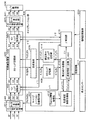
図3は、本実施形態の一例に係るプロジェクタ20内の画像処理部の機能ブロック図である。
【0070】
画像処理部は、RGBの各信号を入力する入力信号処理部401と、色制御処理部420と、補正手段として機能するキャリブレーション部430と、出力信号処理部405と、L/V駆動部406とを含んで構成されている。
【0071】
入力信号処理部401は、R1、G1、B1の各アナログ映像信号をR2、G2、B2の各デジタル映像信号に変換するA/D変換部440を含んで構成されている。
【0072】
色制御処理部420は、入力信号処理用の1D−LUT(1次元ルックアップテーブル)記憶部402と、色情報の補正に用いられる3D−LUT(3次元ルックアップテーブル)記憶部403と、明るさ情報の補正に用いられる1D−LUT記憶部404とを含んで構成されている。
【0073】
なお、より具体的には、1D−LUT記憶部402、404には、明るさ補正用情報の一部として、ガンマテーブルおよびカラーバランステーブル(ただし、どちらか一方の場合もある。)が記憶されている。また、3D−LUT記憶部403には、色補正用情報の一部として、色域補正テーブルおよび色温度補正テーブル(ただし、どちらか一方の場合もある。)が記憶されている。
【0074】
従来は、色制御を1D−LUTにて行い、明るさ補正は入力信号のサンプリング時の電位をどう決めるかによって制御していた。
【0075】
再現される色の明るさを補正する場合、低階調域の出力を上げる必要がある。そこで、階調特性を操作できる1D−LUTにて明るさ補正を行う。
【0076】
さらに、上述したように、色制御で他の色再現域との合わせ込みにあたり、色圧縮、色伸長の適用が色ごとに異なるため、3D−LUTにて色の補正を行う。
【0077】
このように、明るさに関する環境情報と色に関する環境情報に基づき、明るさ補正、色補正を別々に補正、制御することで、それぞれの補正をより的確に行うことができる。
【0078】
以下、色の補正について説明し、次に、明るさの補正について説明する。
【0079】
(色の補正)
キャリブレーション部430は、キャリブレーション(校正)用画像信号を入力信号処理部401に入力するキャリブレーション画像提示部407と、3D−LUT記憶部403に記憶された変換先の色をRGB表色系からXYZ表色系に変換する色変換部408と、色光センサー417から入力される環境情報に基づいて色と明るさの補正を行う環境補正処理部410とを含んで構成されている。
【0080】
なお、RGBはプロジェクタ20等の入出力デバイスによって変化するデバイス依存型の色であり、XYZは、デバイスによらずに同一であるデバイス非依存型の色である。
【0081】
また、キャリブレーション部430は、Gamut情報管理部412と、色度補正係数処理部411とを含んで構成されている。
【0082】
Gamut情報管理部412では、描写する画像の色域情報が管理されている。色域情報は、色度補正係数処理部411に供給され、色度補正係数δの導出に利用される。
【0083】
色度補正係数処理部411は、Gamut情報管理部412からのRGBの色度に基づき、色再現域の複数の相似形の三角形を描く。そして、色度補正係数処理部411は、環境補正処理部410からの色情報(例えば、x1、y1、Y1)に基づき、色度補正係数(例えば、δ(x1、y1、Y1))を導出する。
【0084】
図4は、Y=Y1の場合の色度補正係数δの導出法の例を示す図である。
【0085】
例えば、xy色度図にRGBW(Wは白(グレー))の色三角形を描くと図4のようになる。
【0086】
色度補正係数処理部411は、一番外側の三角形とその1つ内側の三角形(中央の三角形)の間の領域の色度に対する色度補正係数をδ=mξとする。同様に中央の三角形と一番内側の三角形の間の領域の色度に対する色度補正係数をδ=nξとする。ここで、m、nは係数である。また、一番内側の三角形の中の領域の色度に対する色度補正係数をδ=ξとする。
【0087】
このようにして色度補正係数処理部411は、入力信号処理部401から入力される色情報(x1、y1、Y1)に対する色度補正係数(δ(x1、y1、Y1))を求め、色度補正係数を環境補正処理部410に出力する。
【0088】
このように、入力される色に応じて色度補正係数を変更することにより、適切な色再現(色の補正)を行える。
【0089】
また、環境補正処理部410には、色光センサー417から環境情報が入力される。
【0090】
色光センサー417は、視環境を把握する視環境把握手段として機能する。色光センサー417としては、例えば、被表示領域の輝度値を計測する輝度センサー、被表示領域のRGB値やXYZ値を計測する色光センサー、被表示領域の色度値を計測する色度センサー等のうちの1つまたはこれらの組み合わせを適用できる。
【0091】
すなわち、色光センサー417からは複数の環境情報が環境補正処理部410に入力される場合もあり、環境補正処理部410では、入力される環境情報に応じて重み付け(例えば、輝度、色温度、色情報のそれぞれに対する重み付け)をする必要がある。
【0092】
このような重み付けの処理負荷を軽減するため、環境補正処理部410には、複数の環境情報を一括する環境情報一括部450が設けられている。
【0093】
環境情報一括部450は、複数の環境情報に対して所定の処理を施して1つの環境情報に一括する。
【0094】
例えば、色温度または相関色温度は色度座標(x、y)で表現することが可能なため、xyYで一括することが可能である。
【0095】
また、1つの環境情報に一括する処理としては、具体的には例えば、以下の式を適用できる。
【0096】
Δx=a1x1+a2x2+・・・+apxp
Δy=a1y1+a2y2+・・・+aqyq
ΔY=b1Y1+b2Y2+・・・+brYr
ここで、a、bは前述の重みづけの係数である。このようにして、重みづけ処理を一括して行い、様々な環境影響の補正に必要な総合的な補正要求値Δx、Δy、ΔYを導出する。以降の回路等では、Δx、Δy、ΔYを用いることで簡単に必要な補正を施すことが可能である。なお、ここで、Δx、Δy、ΔYは理想状態の環境情報と比較して導出する。
【0097】
環境補正処理部410は、一括された環境情報のうちの色情報(Δx、Δy)を用いて色の補正を行う。
【0098】
具体的には、3D−LUT記憶部403の対応する色を書き換えるため、環境補正処理部410は、3D−LUT記憶部409から入力される色情報(例えば、X1、Y1、Z1)に対して以下の処理を行う。
【0099】
まず、環境補正処理部410は、色度座標(x1、y1)を求めるため、以下の演算を行う。
【0100】
x1=X1/(X1+Y1+Z1)
y1=Y1/(X1+Y1+Z1)
そして、環境補正処理部410は、色度補正係数処理部411に色情報(x1、y1、Y1)を出力し、色度補正係数処理部411から色度補正情報(δ(x1、y1、Y1))を入力する。
【0101】
さらに、環境補正処理部410は、環境情報一括部450で一括処理された環境情報(Δx、Δy)、色度補正情報(δ)および色度(x1、y1)に基づき、色度(x2、y2)を求める。具体的には、例えば、変換式として以下の式を用いることができる。
【0102】
x2=Kx(x1、Δx、δ)
y2=Ky(y1、Δy、δ)
z2=1−x2−y2
X’1=x2(X1+Y1+Z1)
Y’1=y2(X1+Y1+Z1)
Z’1=z2(X1+Y1+Z1)
環境補正処理部410は、このようにして求めた三刺激値(X’1、Y’1、Z’1)を補正済み3D−LUT記憶部414に出力する。
【0103】
そして、色変換部408は、補正済み3D−LUT記憶部414の(X’1、Y’1、Z’1)を(R’1、G’1、B’1)に変換し、変換後の(R’1、G’1、B’1)を3D−LUT記憶部403に出力する。
【0104】
3D−LUT記憶部403では、(R’1、G’1、B’1)を用いて3D−LUTの対応先の色を書き換える。
【0105】
このようにして、視環境に基づき、3D−LUT記憶部403の3D−LUTの色が書き換えられることにより、視環境に応じた適切な色を再現できるようになる。
【0106】
(明るさの補正)
次に、明るさの補正について説明する。
【0107】
明るさの補正は、主に、γ補正部413によって1D−LUT記憶部402および1D−LUT記憶部404に記憶された各1D−LUTのγを補正することによって行われる。
【0108】
上述した手法によって環境補正処理部410により求められたγ補正用のパラメータであるΔYが、環境補正処理部410によってγ補正部413に入力される。
【0109】
γ補正部413は、環境補正処理部410からのΔYに基づき、γ補正処理を行って、1D−LUT記憶部402のγ1をγ’1に変換し、1D−LUT記憶部404のγ2をγ’2に変換する。
【0110】
このようにして、視環境に基づき、1D−LUT記憶部402、404の1D−LUTが書き換えられることにより、視環境に応じた適切な明るさを再現できるようになる。
【0111】
1D−LUT記憶部402、404で明るさの補正がされ、3D−LUT記憶部403で色の補正がなされた各LUT(ルックアップテーブル)を用いて調整された画像信号(R5、G5、B5)が1D−LUT記憶部404から出力信号処理部405に入力される。
【0112】
出力信号処理部405は、D/A変換部441を用いてデジタル画像信号(R5、G5、B5)をアナログ画像信号(R6、G6、B6)に変換し、変換後のアナログ画像信号をL/V駆動部406に出力する。
【0113】
L/V駆動部406は、当該アナログ画像信号を用いて液晶ライトバルブを駆動し、プロジェクタ20から投写する画像を調節する。
【0114】
以上のようにして、プロジェクタ20から投写する画像が調整され、スクリーン10上の画像表示領域12に表示される画像の見え方が適切に調整される。
【0115】
このように、本実施の形態では、視環境を考慮して画像を投写している。
【0116】
これにより、表示環境の差を吸収して、適用される環境によらずに同一の画像を表示することができる。したがって、複数の異なる場所において、ほぼ同一の色を短時間で再現することができる。
【0117】
さらに、階調特性を操作できる1D−LUTを用いて明るさ補正を行うことにより、低階調域の出力を上げ、再現される色の明るさを補正することができる。
【0118】
また、3D−LUTを用いて色の補正を行うことにより、色圧縮、色伸長の適用を色ごとに独立して行うことができる。
【0119】
このように、明るさに関する環境情報と色に関する環境情報に基づき、明るさ補正、色補正を別々に補正、制御することで、それぞれの補正をより的確に行うことができる。
【0120】
(ハードウェアの説明)
なお、上述した各部に用いるハードウェアとしては、例えば、以下のものを適用できる。
【0121】
例えば、入力信号処理部401としては、例えばA/Dコンバーター等、色制御処理部420としては、例えばRAM、CPU等、出力信号処理部405としては、例えばD/Aコンバーター等、L/V駆動部406としては液晶ライトバルブ駆動ドライバ等、キャリブレーション部430としては、例えば画像処理回路等を用いて実現できる。なお、これら各部は回路のようにハードウェア的に実現してもよいし、ドライバのようにソフトウェア的に実現してもよい。
【0122】
また、これらの各部の機能を情報記憶媒体500からプログラムを読み取って実現してもよい。情報記憶媒体500としては、例えば、CD−ROM、DVD−ROM、ROM、RAM、HDD等を適用でき、そのプログラムの読み取り方式は接触方式であっても、非接触方式であってもよい。
【0123】
また、情報記憶媒体500に代えて、上述した各機能を実現するためのプログラム等を、伝送路を介してホスト装置等からダウンロードすることによって上述した各機能を実現することも可能である。
【0124】
以上、本発明を適用した好適な実施の形態について説明してきたが、本発明の適用は上述した実施例に限定されない。
【0125】
(変形例)
例えば、上述した1D−LUT記憶部402、404に記憶されるLUTは、対応表形式のような離散的に値を求めるものであってもよく、関数のように連続的に値を求めるものであってもよい。
【0126】
なお、対応表形式のような離散的な場合には、ラグランジュ補間法、直線補間法等の補間を行うことにより、ほぼ連続的な値(対応する色)を求めることができる。
【0127】
また、上述した実施例では、視環境把握手段として、色光センサー417を用いた例について説明したが、例えば、外光の有無、照明種別、スクリーン種別等を環境情報の少なくとも一部として入力する入力手段を用いてもよく、これらの入力を促す画像を表示する画像表示手段を用いてもよい。また、色光センサー417と、スクリーン種別等の入力用画像とを併用してもよい。
【0128】
特に、スクリーンの場合、その種別は人が容易に判別できるため、例えば、選択肢として提示できる上、人による判断ミスが少なく、スクリーンの種別を正確に反映した色を再現することができる。
【0129】
また、ここで、視環境把握手段が把握する視環境としては、例えば、環境光(照明光、自然光等)や、被表示対象(ディスプレイ、壁面、スクリーン等)等が該当する。
【0130】
特に、スクリーンという従来あまり考慮のされなかった部分についての情報を得ることにより、より適切な画像の補正を行うことができ、より均一な画像の色の再現を行うことができる。
【0131】
なお、上述したスクリーン10は、反射型のものであったが、透過型のものであってもよい。スクリーンが透過型の場合、色光センサーとしては、スクリーンを直接走査するセンサーを適用してもよい。
【0132】
また、上述したプロジェクタのような投写手段以外の表示手段で画像表示を行ってプレゼンテーション等を行う場合にも本発明を適用できる。このような表示手段としては、例えば、液晶プロジェクタのほか、CRT(Cathode Ray Tube)、PDP(Plasma Display Panel)、FED(Field Emission Display)、EL(Electro Luminescence)、直視型液晶表示装置等のディスプレイ装置等が該当する。
【0133】
もちろん、プレゼンテーション以外にも、ミーティング、医療、デザイン・ファッション分野、営業活動、コマーシャル、教育、さらには映画、TV、ビデオ、ゲーム等の一般映像等における画像表示を行う場合にも本発明は有効である。
【0134】
また、A/D変換部440は入力信号(R1、G1、B1)がデジタル形式である場合には不要であり、D/A変換部441も出力信号(R6、G6、B6)がデジタル形式でよい場合には不要である。
【0135】
なお、上述したプロジェクタ20の画像処理部の機能は、単体の画像表示装置(例えば、プロジェクタ20)で実現してもよいし、複数の処理装置で分散して(例えば、プロジェクタ20とPCとで分散処理)実現してもよい。
【0136】
また、上述した実施例では、明るさ情報を含む色情報として、xyY(Yxyともいう。)を用いたが、例えば、Lab、Luv、LCh等を用いてもよい。
【0137】
また、上述した環境情報としては、xyYのように色および明るさを表す値であってもよく、ΔxΔyΔYのように色および明るさの補正量であってもよい。
【0138】
さらに、上述した実施例では、前面投写型のプロジェクタを適用した例について説明したが、背面投写型のプロジェクタを適用することも可能である。
【図面の簡単な説明】
【図1】 本実施形態の一例に係る画像表示システムの概略説明図である。
【図2】 従来のプロジェクタ内の画像処理部の機能ブロック図である。
【図3】 本実施形態の一例に係るプロジェクタ内の画像処理部の機能ブロック図である。
【図4】 Y=Y1の場合の色度補正係数δの導出法の例を示す図である。
【符号の説明】
20 プロジェクタ、80 環境光、402、404 1D−LUT記憶部、403、409 3D−LUT記憶部、410 環境補正処理部、411 色度補正係数処理部、413 γ補正部、417 色光センサー、450 環境情報一括部、500 情報記憶媒体[0001]
BACKGROUND OF THE INVENTION
The present invention relates to an image display system and Image display method About.
[0002]
[Background Art and Problems to be Solved by the Invention]
When displaying images in presentations, meetings, medical care, design / fashion fields, sales activities, commercials, education, and general images such as movies, TV, videos, games, etc. Can be reproduced at any place is important for effective presentations.
[0003]
As an idea for adjusting the appearance of such an image, there is an idea of color management for reproducing colors by managing input / output characteristics of a device, but the specific method is not clear.
[0004]
In particular, when an image is projected using a screen and a projector, it is difficult to reproduce appropriate colors without considering not only ambient light but also the type of screen.
[0005]
In recent years, projectors have been improved in definition and color reproducibility has become important.
[0006]
Further, in a conventional projector, a 1D-LUT (one-dimensional look-up table) is used for purposes such as color temperature adjustment, γ correction, and correction of display element characteristics.
[0007]
However, when performing advanced color management, it is necessary to match the color gamut with other display devices or standard color spaces (such as sRGB) having different color gamuts.
[0008]
It is also necessary to match the color gamut of the display device that has changed due to environmental influences with the color gamut of other display devices or a standard color space. In such adjustment of the color gamut, corrections such as color compression and color expansion are performed.
[0009]
When the two color gamuts are combined, a part of one color gamut protrudes from the other color gamut, and another part of one color gamut lies within the range of the other color gamut. For this reason, it is necessary to perform correction such that a specific color area is compressed and another specific color area is expanded in the same color reproduction range.
[0010]
Such color control for each specific region is difficult to achieve with a 1D-LUT that is controlled by gamma for each RGB. Even if the 1D-LUT is a correspondence table, only the primary colors can be controlled, so it is difficult to perform different control for each color.
[0011]
The present invention has been made in view of the above problems, and an object of the present invention is to provide an image display system capable of reproducing substantially the same color in a short time at a plurality of different locations. Image display method Is to provide.
[0012]
[Means for Solving the Problems]
In order to solve the above problems, an image display system according to the present invention is an image display system that corrects and displays the image based on environment information indicating a visual environment in a display area of the image,
Brightness correction information for correcting the brightness of the image based on the environment information;
Color correction information for correcting the color of the image based on the environment information;
Means for storing
Correction means for correcting image information for displaying the image based on the environment information, the brightness correction information, and the color correction information;
It is characterized by including.
[0013]
An information storage medium according to the present invention is a computer-readable information storage medium storing a program for correcting and displaying the image based on environmental information indicating a viewing environment in a display area of the image. ,
Computer
Brightness correction information for correcting the brightness of the image based on the environment information;
Color correction information for correcting the color of the image based on the environment information;
Means for storing in a predetermined storage area;
A program for functioning as correction means for correcting image information for displaying the image is stored based on the environment information, the brightness correction information, and the color correction information.
[0014]
According to the present invention, when correcting an image using environment information, brightness and color are more flexibly corrected by separately managing brightness correction information and color correction information. be able to.
[0015]
For example, conventionally, a 1D-LUT (one-dimensional lookup table) has been used for purposes such as color temperature adjustment, γ correction, and correction of display element characteristics.
[0016]
However, when performing advanced color management, it is necessary to match the color gamut with other display devices or standard color spaces (such as sRGB) having different color gamuts.
[0017]
It is also necessary to match the color gamut of the display device that has changed due to environmental influences with the color gamut of other display devices or a standard color space. In such adjustment of the color gamut, corrections such as color compression and color expansion are performed.
[0018]
When the two color gamuts are combined, a part of one color gamut protrudes from the other color gamut, and another part of one color gamut lies within the range of the other color gamut. For this reason, it is necessary to perform correction such that a specific color area is compressed and another specific color area is expanded in the same color reproduction range.
[0019]
Such color control for each specific region is difficult to achieve with a 1D-LUT that is controlled by gamma for each RGB. Even if the 1D-LUT is a correspondence table, only the primary colors can be controlled, so it is difficult to perform different control for each color. On the other hand, since the 3D-LUT (three-dimensional lookup table) can be controlled for each color for colors other than the primary colors, different control (color compression / color expansion) is performed for each color region as described above. Is possible.
[0020]
By using the 3D-LUT, it is possible to control different color compression, color expansion, and the like for each color region that is difficult with the 1D-LUT, and accurate color reproduction can be performed.
[0021]
As described above, by appropriately managing the 1D-LUT for brightness correction and the 3D-LUT for color correction, more appropriate color reproduction can be performed.
[0022]
Thereby, the same image can be displayed irrespective of the environment applied by absorbing the difference in display environment. Therefore, substantially the same color can be reproduced in a short time at a plurality of different locations.
[0023]
Here, as the visual environment, for example, environmental light (illumination light, natural light, etc.), a display target (display, wall surface, screen, etc.), and the like are applicable.
[0024]
The environment information includes, for example, a value representing color and brightness such as xyY, and a color and brightness correction amount such as ΔxΔyΔY.
[0025]
Moreover, when realizing such an image display system, it can be realized using, for example, a projector, a monitor, or the like.
[0026]
The brightness correction information includes a one-dimensional lookup table,
The color correction information may include a three-dimensional lookup table.
[0027]
The one-dimensional lookup table includes at least one of a gamma table and a color balance table,
The three-dimensional lookup table may include at least one of a color gamut correction table and a color temperature correction table.
[0028]
The correction means includes
Including a means to batch input multiple types of environmental information;
The image information may be corrected based on the collected environmental information.
[0029]
According to this, even when a plurality of types of environmental information are input, the subsequent correction processing can be performed quickly by collecting them together.
[0030]
Here, as post-collection information, for example, xyY, Luv, Lab, XYZ, or the like can be used.
[0031]
The correction unit may change a predetermined correction coefficient used for correcting the image information based on the environment information.
[0032]
According to this, for example, by changing the default correction coefficient set by the manufacturer according to the target color, it is possible to perform appropriate color reproduction according to the actual visual environment.
[0033]
The image display system may include a visual environment grasping unit that measures at least one of a color value, a gamma, and a color temperature of an image displayed in the display area.
[0034]
In the information storage medium, the environment information may be information by a visual environment grasping unit that measures at least one of the color value, gamma, and color temperature of the image displayed in the display area.
[0035]
The visual environment grasping means includes, for example, a luminance sensor that measures the luminance value of the display area, a color light sensor that measures the RGB value and XYZ value of the display area, and a color that measures the chromaticity value of the display area. One or a combination of degree sensors or the like can be applied.
[0036]
Here, the color value means an index capable of expressing colors such as tristimulus values, chromaticity coordinates, spectral distribution, stimulus purity and dominant wavelength.
[0037]
Further, the display area may be an area on a screen.
[0038]
The present image display system can be applied satisfactorily even when the color appearance changes greatly depending on the material such as a screen.
[0039]
Further, the image display system includes means for displaying an image prompting input of the screen type,
Means for inputting the type of the input screen as at least part of the environmental information;
May be included.
[0040]
Further, the information storage medium has a computer for displaying an image prompting an input of the screen type,
You may memorize | store the program for functioning as a means to input the input classification of the said screen as at least one part of the said environment information.
[0041]
According to this, it is possible to appropriately correct the color and brightness of an image by grasping the visual environment that has not been considered in the past, such as a screen.
[0042]
In particular, since there are few types of screens and humans can easily discriminate them, there are few judgment errors when inputting the type of screen, so that the type of screen can be accurately grasped.
[0043]
The screen may be a reflective type or a transmissive type.
[0044]
The visual environment grasping means may grasp a visual environment reflecting the type of the screen.
[0045]
For example, the visual environment grasping means may include a sensor for grasping screen characteristics.
[0046]
Specifically, the characteristics of the screen can be grasped by measuring reflected light (transmitted light) when white light is projected with a sensor such as a color light sensor.
[0047]
According to this, it is possible to absorb the difference in the screen type by grasping the visual environment reflecting the type of the screen and performing gamma correction, color temperature correction or the like based on the grasped result. This makes it possible to reproduce an image with the same color appearance regardless of the type of screen.
[0048]
In particular, a PC or the like using an OS or the like incorporating a conventional color management system merely considers the type of display connected to the PC. There have also been proposals for correcting colors in consideration of ambient light, but none of them considers a screen that is a display area of an image.
[0049]
According to the present invention, it is possible to generate and display an image that appropriately reflects the viewing environment by grasping the viewing environment that reflects the type of screen and performing color correction.
[0050]
In the image display system, the visual environment grasping unit may include a unit that measures at least ambient light to grasp the visual environment.
[0051]
In the information storage medium, the visual environment grasping means may grasp a visual environment reflecting at least ambient light.
[0052]
According to this, it is possible to grasp the visual environment by measuring ambient light or the like. In the visual environment, ambient light greatly affects the appearance of an image. The visual environment can be appropriately grasped by measuring the ambient light which is the main factor of the appearance of the image.
[0053]
DETAILED DESCRIPTION OF THE INVENTION
Hereinafter, a case where the present invention is applied to an image display system using a liquid crystal projector will be described as an example with reference to the drawings.
[0054]
(Description of the entire system)
FIG. 1 is a schematic explanatory diagram of an image display system according to an example of the present embodiment.
[0055]
A predetermined presentation image is projected from the
[0056]
When such a presentation is performed, the appearance of the image in the
[0057]
In recent years, the
[0058]
FIG. 2 is a functional block diagram of an image processing unit in a conventional projector.
[0059]
In a conventional projector, an R1 signal, a G1 signal, and a B1 signal constituting an analog RGB signal sent from a PC or the like are input to an A /
[0060]
Then, the color-converted R3 signal, G3 signal, and B3 signal are input to the D /
[0061]
Further, the projector
[0062]
The projector
[0063]
As described above, in the conventional projector, only the color conversion is performed based on the input / output profile indicating the input / output characteristics unique to the projector, and the viewing environment in which the image is projected is not taken into consideration.
[0064]
However, as described above, it is difficult to unify the color appearance without considering the visual environment. The color appearance is determined by three factors: light, reflection or transmission of light of the object, and vision.
[0065]
In this embodiment, an image display system capable of reproducing an image with the same color appearance regardless of the environment to be applied is realized by grasping the visual environment reflecting the reflection or transmission of light and target light. ing.
[0066]
Specifically, as shown in FIG. 1, a
[0067]
The
[0068]
Next, functional blocks of the image processing unit of the
[0069]
FIG. 3 is a functional block diagram of the image processing unit in the
[0070]
The image processing unit includes an input signal processing unit 401 that inputs RGB signals, a color
[0071]
The input signal processing unit 401 includes an A / D conversion unit 440 that converts R1, G1, and B1 analog video signals into R2, G2, and B2 digital video signals.
[0072]
The color
[0073]
More specifically, the 1D-
[0074]
Conventionally, color control is performed by a 1D-LUT, and brightness correction is controlled by how to determine the potential at the time of sampling the input signal.
[0075]
When correcting the brightness of the reproduced color, it is necessary to increase the output of the low gradation range. Therefore, brightness correction is performed using a 1D-LUT capable of manipulating gradation characteristics.
[0076]
Furthermore, as described above, since the application of color compression and color expansion differs for each color when combining with other color reproduction areas in color control, color correction is performed with a 3D-LUT.
[0077]
As described above, by correcting and controlling the brightness correction and the color correction separately based on the environment information about the brightness and the environment information about the color, each correction can be performed more accurately.
[0078]
Hereinafter, color correction will be described, and then brightness correction will be described.
[0079]
(Color correction)
The
[0080]
Note that RGB is a device-dependent color that varies depending on an input / output device such as the
[0081]
The
[0082]
The Gamut
[0083]
The chromaticity correction
[0084]
FIG. 4 is a diagram illustrating an example of a method for deriving the chromaticity correction coefficient δ when Y = Y1.
[0085]
For example, when a color triangle of RGBW (W is white (gray)) is drawn on the xy chromaticity diagram, the result is as shown in FIG.
[0086]
The chromaticity correction
[0087]
In this way, the chromaticity correction
[0088]
In this manner, appropriate color reproduction (color correction) can be performed by changing the chromaticity correction coefficient in accordance with the input color.
[0089]
In addition, environment information is input from the
[0090]
The
[0091]
That is, a plurality of environment information may be input from the
[0092]
In order to reduce such a weighting processing load, the environment
[0093]
The environment
[0094]
For example, since the color temperature or the correlated color temperature can be expressed by chromaticity coordinates (x, y), they can be collectively expressed by xyY.
[0095]
For example, the following formula can be applied as a process for batching into one environment information.
[0096]
Δx = a1x1 + a2x2 + ... + apxp
Δy = a1y1 + a2y2 + ... + aqyq
ΔY = b1Y1 + b2Y2 + ... + brYr
Here, a and b are the aforementioned weighting coefficients. In this way, the weighting process is performed collectively to derive comprehensive correction request values Δx, Δy, ΔY necessary for correcting various environmental effects. In subsequent circuits and the like, necessary correction can be easily performed by using Δx, Δy, and ΔY. Here, Δx, Δy, and ΔY are derived by comparing with the environmental information in the ideal state.
[0097]
The environment
[0098]
Specifically, in order to rewrite the corresponding color in the 3D-
[0099]
First, the environment
[0100]
x1 = X1 / (X1 + Y1 + Z1)
y1 = Y1 / (X1 + Y1 + Z1)
Then, the environment
[0101]
Further, the environment
[0102]
x2 = Kx (x1, Δx, δ)
y2 = Ky (y1, Δy, δ)
z2 = 1-x2-y2
X′1 = x2 (X1 + Y1 + Z1)
Y′1 = y2 (X1 + Y1 + Z1)
Z′1 = z2 (X1 + Y1 + Z1)
The environment
[0103]
Then, the
[0104]
The 3D-
[0105]
In this way, by rewriting the 3D-LUT color in the 3D-
[0106]
(Brightness correction)
Next, brightness correction will be described.
[0107]
The correction of brightness is mainly performed by correcting γ of each 1D-LUT stored in the 1D-
[0108]
ΔY, which is a parameter for γ correction obtained by the environment
[0109]
The
[0110]
In this way, by rewriting the 1D-LUT in the 1D-
[0111]
Image signals (R5, G5, B5) adjusted using the respective LUTs (look-up tables) that have been corrected for brightness by the 1D-
[0112]
The output signal processing unit 405 converts the digital image signal (R5, G5, B5) into an analog image signal (R6, G6, B6) using the D / A conversion unit 441, and converts the converted analog image signal to L / Output to the
[0113]
The L /
[0114]
As described above, the image projected from the
[0115]
Thus, in this embodiment, an image is projected in consideration of the visual environment.
[0116]
Thereby, the difference of display environment can be absorbed and the same image can be displayed irrespective of the environment applied. Therefore, substantially the same color can be reproduced in a short time at a plurality of different locations.
[0117]
Furthermore, by performing brightness correction using a 1D-LUT capable of manipulating the gradation characteristics, it is possible to increase the output of the low gradation region and correct the brightness of the reproduced color.
[0118]
In addition, by performing color correction using a 3D-LUT, color compression and color expansion can be applied independently for each color.
[0119]
As described above, by correcting and controlling the brightness correction and the color correction separately based on the environment information about the brightness and the environment information about the color, each correction can be performed more accurately.
[0120]
(Hardware description)
In addition, as hardware used for each part mentioned above, the following can be applied, for example.
[0121]
For example, the input signal processing unit 401 is, for example, an A / D converter, the color
[0122]
Further, the functions of these units may be realized by reading a program from the
[0123]
Further, instead of the
[0124]
The preferred embodiments to which the present invention is applied have been described above, but the application of the present invention is not limited to the above-described examples.
[0125]
(Modification)
For example, the above-described LUTs stored in the 1D-
[0126]
In a discrete case such as a correspondence table format, a substantially continuous value (corresponding color) can be obtained by performing interpolation such as Lagrangian interpolation or linear interpolation.
[0127]
In the above-described embodiment, the example using the
[0128]
In particular, in the case of a screen, since the type can be easily identified by a person, for example, it can be presented as an option, and it is possible to reproduce a color that accurately reflects the type of the screen with few judgment errors by a person.
[0129]
Here, as the visual environment grasped by the visual environment grasping means, for example, environmental light (illumination light, natural light, etc.), a display target (display, wall surface, screen, etc.), and the like are applicable.
[0130]
In particular, by obtaining information about a portion of the screen that has not been considered so far, more appropriate image correction can be performed, and more uniform image color reproduction can be performed.
[0131]
The
[0132]
The present invention can also be applied to a case where an image is displayed by a display unit other than the projection unit such as the projector described above to give a presentation. Examples of such display means include liquid crystal projectors, displays such as CRT (Cathode Ray Tube), PDP (Plasma Display Panel), FED (Field Emission Display), EL (Electro Luminescence), and direct view type liquid crystal display devices. Applicable to devices.
[0133]
Of course, in addition to presentations, the present invention is also effective when displaying images in meetings, medical care, design / fashion fields, sales activities, commercials, education, and general images such as movies, TVs, videos, and games. is there.
[0134]
Further, the A / D converter 440 is not necessary when the input signals (R1, G1, B1) are in a digital format, and the D / A converter 441 also has an output signal (R6, G6, B6) in a digital format. It is unnecessary if it is good.
[0135]
Note that the functions of the image processing unit of the
[0136]
In the above-described embodiment, xyY (also referred to as Yxy) is used as color information including brightness information. However, for example, Lab, Luv, LCh, or the like may be used.
[0137]
Further, the environmental information described above may be a value representing color and brightness such as xyY, or may be a correction amount of color and brightness such as ΔxΔyΔY.
[0138]
Further, in the above-described embodiment, the example in which the front projection type projector is applied has been described. However, it is also possible to apply the rear projection type projector.
[Brief description of the drawings]
FIG. 1 is a schematic explanatory diagram of an image display system according to an example of an embodiment.
FIG. 2 is a functional block diagram of an image processing unit in a conventional projector.
FIG. 3 is a functional block diagram of an image processing unit in the projector according to an example of the present embodiment.
FIG. 4 is a diagram illustrating an example of a method for deriving a chromaticity correction coefficient δ when Y = Y1.
[Explanation of symbols]
20 projector, 80 ambient light, 402, 404 1D-LUT storage unit, 403, 409 3D-LUT storage unit, 410 environment correction processing unit, 411 chromaticity correction coefficient processing unit, 413 γ correction unit, 417 color light sensor, 450 environment Information batch section, 500 information storage medium
Claims (6)
入力された前記スクリーンの種別に応じたスクリーン特性を、色および明るさを表す第1の環境情報として入力する第1の入力手段と、
環境光に関する情報を第2の環境情報として入力する第2の入力手段と、
前記第1および第2の環境情報に基づき、色および明るさの補正量を示す情報を生成するとともに、当該色および明るさの補正量を示す情報に基づき、前記画像を表示するための画像情報を補正する補正手段と、
を含み、
前記補正手段は、前記第1および第2の環境情報に対して所定の重み付け演算を行うことにより、前記色および明るさの補正量を示す情報を生成することを特徴とする画像表示システム。Means for displaying an image for input of a screen type which is a display area of the image;
First input means for inputting screen characteristics corresponding to the type of the input screen as first environmental information representing color and brightness;
Second input means for inputting information relating to ambient light as second environmental information;
Image information for generating the information indicating the correction amount of the color and brightness based on the first and second environment information, and displaying the image based on the information indicating the correction amount of the color and brightness. Correction means for correcting
Only including,
The image display system according to claim 1, wherein the correction unit generates information indicating a correction amount of the color and brightness by performing a predetermined weighting operation on the first and second environment information .
前記画像の明るさを補正するための明るさ補正用情報と、前記画像の色を補正するための色補正用情報とを記憶する手段を含み、
前記補正手段は、前記明るさ補正用情報と、前記色補正用情報と、前記色および明るさの補正量を示す情報とに基づき、前記画像情報を補正することを特徴とする画像表示システム。Oite to claim 1,
Means for storing brightness correction information for correcting the brightness of the image and color correction information for correcting the color of the image;
The image display system, wherein the correction means corrects the image information based on the brightness correction information, the color correction information, and information indicating the correction amount of the color and brightness.
前記補正手段は、
前記明るさの補正量に基づいて前記明るさ補正用情報を補正し、
前記色の補正量に基づいて前記色補正用情報を補正し、
前記明るさ補正用情報および前記色補正用情報に基づき、前記画像を表示するための画像情報を補正することを特徴とする画像表示システム。In claim 2 ,
The correction means includes
Correcting the brightness correction information based on the brightness correction amount;
Correcting the color correction information based on the color correction amount;
An image display system, wherein image information for displaying the image is corrected based on the brightness correction information and the color correction information.
前記明るさ補正用情報は、1次元ルックアップテーブルを含み、
前記色補正用情報は、3次元ルックアップテーブルを含むことを特徴とする画像表示システム。In any one of Claims 2 and 3 ,
The brightness correction information includes a one-dimensional lookup table,
The image display system, wherein the color correction information includes a three-dimensional lookup table.
前記1次元ルックアップテーブルは、ガンマテーブルおよびカラーバランステーブルの少なくとも一方を含み、
前記3次元ルックアップテーブルは、色域補正テーブルおよび色温度補正テーブルの少なくとも一方を含むことを特徴とする画像表示システム。In claim 4 ,
The one-dimensional lookup table includes at least one of a gamma table and a color balance table;
The image display system, wherein the three-dimensional lookup table includes at least one of a color gamut correction table and a color temperature correction table.
画像の被表示領域であるスクリーンの種別の入力用の画像を表示するステップと、
入力された前記スクリーンの種別に応じたスクリーン特性を、色および明るさを表す第1の環境情報として入力する第1の入力ステップと、
環境光に関する情報を第2の環境情報として入力する第2の入力ステップと、
前記第1および第2の環境情報に対して所定の重み付け演算を行うことにより、色および明るさの補正量を示す情報を生成するステップと、
当該色および明るさの補正量を示す情報に基づき、前記画像を表示するための画像情報を補正するステップと、
を実行することを特徴とする画像表示方法。The image display system
Displaying an image for input of a screen type that is a display area of the image;
A first input step of inputting screen characteristics according to the type of the input screen as first environmental information representing color and brightness;
A second input step of inputting information relating to ambient light as second environmental information;
By performing predetermined weighting calculation for the first and second environmental information, and generating information indicating the amount of correction of color and brightness,
Correcting image information for displaying the image based on the information indicating the correction amount of the color and brightness;
The image display method characterized by performing.
Priority Applications (1)
| Application Number | Priority Date | Filing Date | Title |
|---|---|---|---|
| JP2003123341A JP4164659B2 (en) | 2003-04-28 | 2003-04-28 | Image display system and image display method |
Applications Claiming Priority (1)
| Application Number | Priority Date | Filing Date | Title |
|---|---|---|---|
| JP2003123341A JP4164659B2 (en) | 2003-04-28 | 2003-04-28 | Image display system and image display method |
Related Parent Applications (1)
| Application Number | Title | Priority Date | Filing Date |
|---|---|---|---|
| JP2000230950A Division JP3632574B2 (en) | 2000-07-31 | 2000-07-31 | Environment-adaptive image display system and information storage medium |
Publications (3)
| Publication Number | Publication Date |
|---|---|
| JP2004004808A JP2004004808A (en) | 2004-01-08 |
| JP2004004808A5 JP2004004808A5 (en) | 2007-09-06 |
| JP4164659B2 true JP4164659B2 (en) | 2008-10-15 |
Family
ID=30438017
Family Applications (1)
| Application Number | Title | Priority Date | Filing Date |
|---|---|---|---|
| JP2003123341A Expired - Fee Related JP4164659B2 (en) | 2003-04-28 | 2003-04-28 | Image display system and image display method |
Country Status (1)
| Country | Link |
|---|---|
| JP (1) | JP4164659B2 (en) |
-
2003
- 2003-04-28 JP JP2003123341A patent/JP4164659B2/en not_active Expired - Fee Related
Also Published As
| Publication number | Publication date |
|---|---|
| JP2004004808A (en) | 2004-01-08 |
Similar Documents
| Publication | Publication Date | Title |
|---|---|---|
| JP3632574B2 (en) | Environment-adaptive image display system and information storage medium | |
| JP3719411B2 (en) | Image display system, projector, program, information storage medium, and image processing method | |
| JP4605987B2 (en) | Projector, image processing method, and information storage medium | |
| JP3692989B2 (en) | Image display system, projector, image processing method, program, and information storage medium | |
| JP4110408B2 (en) | Image display system, projector, image processing method, and information storage medium | |
| US7595811B2 (en) | Environment-complaint image display system, projector, and program | |
| JP3894302B2 (en) | Image display system, image processing method, program, and information storage medium | |
| US6847374B2 (en) | Environment-compliant image display system and program | |
| JP3755593B2 (en) | Projection-type image display system, projector, program, information storage medium, and image processing method | |
| EP1370092A1 (en) | Environment-adaptive image display system, information storage medium, and image processing method | |
| JP4743424B2 (en) | Image display system, projector, program, and information storage medium | |
| JP2014072855A (en) | Image display apparatus | |
| JP2002125125A (en) | Image display system of environment adaptation type, program and information storage medium | |
| JP4150876B2 (en) | Image display system, image processing method, program, and information storage medium | |
| JP4164659B2 (en) | Image display system and image display method |
Legal Events
| Date | Code | Title | Description |
|---|---|---|---|
| RD04 | Notification of resignation of power of attorney |
Free format text: JAPANESE INTERMEDIATE CODE: A7424 Effective date: 20060112 |
|
| A521 | Written amendment |
Free format text: JAPANESE INTERMEDIATE CODE: A523 Effective date: 20070719 |
|
| A621 | Written request for application examination |
Free format text: JAPANESE INTERMEDIATE CODE: A621 Effective date: 20070719 |
|
| A131 | Notification of reasons for refusal |
Free format text: JAPANESE INTERMEDIATE CODE: A131 Effective date: 20080305 |
|
| A521 | Written amendment |
Free format text: JAPANESE INTERMEDIATE CODE: A523 Effective date: 20080417 |
|
| TRDD | Decision of grant or rejection written | ||
| A01 | Written decision to grant a patent or to grant a registration (utility model) |
Free format text: JAPANESE INTERMEDIATE CODE: A01 Effective date: 20080702 |
|
| A01 | Written decision to grant a patent or to grant a registration (utility model) |
Free format text: JAPANESE INTERMEDIATE CODE: A01 |
|
| A61 | First payment of annual fees (during grant procedure) |
Free format text: JAPANESE INTERMEDIATE CODE: A61 Effective date: 20080715 |
|
| R150 | Certificate of patent or registration of utility model |
Free format text: JAPANESE INTERMEDIATE CODE: R150 |
|
| FPAY | Renewal fee payment (event date is renewal date of database) |
Free format text: PAYMENT UNTIL: 20110808 Year of fee payment: 3 |
|
| FPAY | Renewal fee payment (event date is renewal date of database) |
Free format text: PAYMENT UNTIL: 20120808 Year of fee payment: 4 |
|
| FPAY | Renewal fee payment (event date is renewal date of database) |
Free format text: PAYMENT UNTIL: 20130808 Year of fee payment: 5 |
|
| S531 | Written request for registration of change of domicile |
Free format text: JAPANESE INTERMEDIATE CODE: R313531 |
|
| R350 | Written notification of registration of transfer |
Free format text: JAPANESE INTERMEDIATE CODE: R350 |
|
| LAPS | Cancellation because of no payment of annual fees |