明 細 書 マルチビジョンシステム及びカラーキヤリブレーション方法及びディス プレイ装置 技術分野 Description Multi-vision system, color calibration method and display device
この発明は、 デイスプレイ装置及び複数のディスプレイ装置によって 構成されるマルチビジョンシステムのカラーキヤリブレーションに関す るものである。 背景技術 The present invention relates to color calibration of a multi-vision system including a display device and a plurality of display devices. Background art
図 1 6, 図 1 7は、 例えば、 特開平 7— 7 2 8 1 7号公報に示された 従来の複数ディスプレイ装置より成るマルチビジョンの輝度制御装置の 部分断面図と要部のプロック図である。 FIGS. 16 and 17 are a partial cross-sectional view and a block diagram of a main part of a conventional multi-vision brightness control device including a plurality of display devices disclosed in Japanese Patent Application Laid-Open No. 7-72817, for example. is there.
また、 図 1 8は、 同マルチビジョンの輝度制御装置の動作のフローチ ヤートである。 Fig. 18 is a flowchart of the operation of the multi-vision brightness control device.
図 1 6 , 図 1 7において、 R 1はスクリーン、 R 3は外周の輝度を検 知するセンサ、 R 5は壁、 R 6は天井、 R 7は収納棚、 R 3 1は天窓、 R 8は投写ユニッ ト、 R 9は投写ユニッ ト R 8のレンズブロック、 R 1 0は投写ュニッ ト R 8の制御基板、 R 1 1は投写ュ二ッ ト R 8のブラゥ ン管、 R 1 2は投写ユニット R 8の操作盤、 R 1 3はセンサ R 3の信号 を制御基板に伝達するリ一ド線である。 In Figs. 16 and 17, R1 is a screen, R3 is a sensor that detects the brightness of the outer periphery, R5 is a wall, R6 is a ceiling, R7 is a storage shelf, R31 is a skylight, and R8. Is the projection unit, R9 is the lens block of the projection unit R8, R10 is the control board of the projection unit R8, R11 is the projection tube of the projection unit R8, and R12 is The operation panel R13 of the projection unit R8 is a lead wire for transmitting the signal of the sensor R3 to the control board.
スクリーン R 1は複数枚であり、 スクリーン R 1に対して、 投写ュ二 ッ ト R 8は 1 : 1に対応し、 その映像はスクリーン R 1に投写される。 スクリーン枠の外周にセンサ R 3を配備し、 スクリーン枠に照射される 光線の輝度が検知できる。 センサ R 3によって検知された輝度情報は、
リード線 R l 3により制御基板 R l 0に送られ、 記憶、 演算されてブラ ゥン管 R 1 1に輝度を設定する。 There are a plurality of screens R1, and the projection unit R8 corresponds to 1: 1 with respect to the screen R1, and the image is projected on the screen R1. A sensor R3 is provided on the outer periphery of the screen frame to detect the brightness of the light beam applied to the screen frame. The luminance information detected by the sensor R 3 is The signal is sent to the control board R10 by the lead wire R13, stored and calculated, and the brightness is set to the tube tube R11.
以下、 上記構成のマルチビジョンの輝度制御装置の動作について、 図 1 8を参照して更に詳細に説明する。 Hereinafter, the operation of the multi-vision luminance control device having the above configuration will be described in more detail with reference to FIG.
まず、 マルチビジョンに電源を投入させ、 起動させる。 次に、 制御回 路内の各記憶装置の内容をゼロクリアし、 一定時間たつたら時間カウン ター tをゼロクリアし、 周辺の輝度をセンサ R 3より検知し、 周囲の輝 度情報を制御基板 R 1 0にリード線 1 3により入力する。 制御基板 R 1 0は、 周囲の輝度情報によりブラウン管 R 1 1の輝度の数値を周囲の輝 度に応じて見やすくなる最小の輝度になるよう仕組まれた演算を施し、 演算された結果をブラウン管に入力し輝度を設定して映像をスクリーン に写し、 その後、 装置の停止があれば停止処理を行い、 なければ、 再び 輝度の検知から処理を繰り返す。 First, power on the multivision and start it. Next, the contents of each storage device in the control circuit are cleared to zero, the time counter t is cleared to zero after a certain time, the surrounding brightness is detected by the sensor R3, and the surrounding brightness information is read from the control board R1. Input 0 to lead 13. The control board R 10 performs an operation designed to minimize the brightness value of the cathode ray tube R 11 according to the surrounding brightness based on the surrounding brightness information so as to make it easy to see, and the calculated result is sent to the cathode ray tube. Input and set the brightness and project the image on the screen. After that, if the device is stopped, stop the process. If not, repeat the process from detecting the brightness again.
従来例のマルチビジョンは、 上記のように輝度の制御をしていた。 セ ンサ R 3で得られる情報が輝度の情報だけであるために、 その時の周囲 の環境に応じて最適な輝度の設定しかできず、 表示色の制御ができなか つた。 In the conventional multivision, the luminance is controlled as described above. Since the information obtained by the sensor R3 is only luminance information, only the optimal luminance can be set according to the surrounding environment at that time, and the display color cannot be controlled.
また、 センサ R 3がスクリーン各々に対して、 設定されていないため に、 各スク リーン間で表示色の相違があっても、 それを検知できないの で、 スク リーン毎の色の制御ができず、 色の不均一なままでしか表示が できなかった。 Also, since the sensor R3 is not set for each screen, even if there is a difference in display color between screens, it cannot be detected, so that color control for each screen cannot be performed. However, display was possible only with uneven color.
本発明は、 ディスプレイ装置の表示色をターゲット色に合わせること を目的とする。 An object of the present invention is to match a display color of a display device with a target color.
更に、 本発明では、 マルチビジョンシステム内の複数のディスプレイ 装置の表示色を同一のターゲット色に合わせ、 ディスプレイ装置間で表 示する色の差をなくすることを目的とする。
更に、 本発明では、 マルチビジョンシステム内の複数のディスプレイ 装置の表示色を合わせる目標となるターゲッ ト色を最適に選択し、 全体 の色合わせの性能を上げることを目的とする。 Another object of the present invention is to match the display colors of a plurality of display devices in a multi-vision system with the same target color to eliminate the difference in colors displayed between the display devices. Further, it is an object of the present invention to optimally select a target color as a target for matching the display colors of a plurality of display devices in a multi-vision system, and to improve the overall color matching performance.
更に、 構成の簡単な装置で、 なるべく人の手を介さないで自動的に上 記のカラーキヤリブレーションを行うことを目的とする。 発明の開示 It is another object of the present invention to automatically perform the above-described color calibration with a device having a simple structure and as little as possible with human intervention. Disclosure of the invention
この発明に係るマルチビジョンシステムは、 複数のディスプレイ装置 から構成されるマルチビジョンシステムにおいて、 A multi-vision system according to the present invention is a multi-vision system including a plurality of display devices.
複数のデイスプレイ装置の表示色を測色するセンサと、 A sensor for measuring display colors of a plurality of display devices,
上記センサにより測色された複数のディスプレイ装置の表示色の測色 値より各ディスプレイ装置の表示色をキヤリブレーションするための色 変換係数を算出する色変換係数演算部と、 A color conversion coefficient calculation unit that calculates a color conversion coefficient for calibrating the display color of each display device from the colorimetric values of the display colors of the plurality of display devices measured by the sensor,
上記色変換係数演算部により算出された色変換係数を用いて各ディス プレイ装置の表示色の色変換を行う色処理部と A color processing unit that performs color conversion of the display color of each display device using the color conversion coefficient calculated by the color conversion coefficient calculation unit;
を備えたことを特徴とする。 It is characterized by having.
上記色処理部は、 少なく とも 1つ以上の代表色の信号を受け、 上記代 表色を色変換なしにディスプレイ装置上に表示し、 The color processing unit receives a signal of at least one or more representative colors, displays the representative color on a display device without color conversion,
上記センサは、 上記色処理部が表示した複数のディスプレイ装置上の 代表色を測色し、 The sensor measures a representative color displayed on the plurality of display devices by the color processing unit,
上記色変換係数演算部は、 上記センサが測色した代表色が予め定めた ターゲッ ト色になるように色変換するための各ディスプレイ装置の色変 換係数を算出し、 算出された色変換係数を色処理部に出力することを特 徴とする。 The color conversion coefficient calculation unit calculates a color conversion coefficient of each display device for performing color conversion so that the representative color measured by the sensor becomes a predetermined target color, and calculates the calculated color conversion coefficient. Is output to the color processing unit.
上記センサは、 マルチビジョンシステム内に内蔵され、 複数のデイス プレイ装置の間の非表示エリアに設置されていることを特徴とする。
上記センサは、 マルチビジョンシステム外側に設置されていることを 特徴とする。 The sensor is built in a multi-vision system and is installed in a non-display area between a plurality of display devices. The sensor is installed outside the multi-vision system.
上記センサは、 複数のディスプレイ装置に対して平行走査可能に設置 されていることを特徴とする。 The sensor is installed so as to be capable of parallel scanning with respect to a plurality of display devices.
上記色変換係数演算部は、 少なく とも 1つ以上の代表色の信号値を決 定しておき、 前記代表色を複数のデイスプレイ装置に色変換なしに表示 した時の代表色の測色値の中で、 複数のディスプレイ装置の色再現領域 内で、 共通の色再現域を最大にとれる測色値をその代表色のターゲッ ト 色とすることを特徴とする。 The color conversion coefficient calculation unit determines signal values of at least one or more representative colors, and calculates a colorimetric value of the representative color when the representative colors are displayed on a plurality of display devices without color conversion. Among them, a colorimetric value which can maximize a common color gamut within a color gamut of a plurality of display devices is set as a target color of the representative color.
上記色変換係数演算部は、 複数のディスプレイ装置の少なく とも 1つ 以上の代表色の測色値を色度座標上に表示し、 指示された色度座標によ りターゲッ ト色を決定することを特徴とする。 The color conversion coefficient calculator displays colorimetric values of at least one or more representative colors of a plurality of display devices on chromaticity coordinates, and determines a target color based on the designated chromaticity coordinates. It is characterized by.
上記色変換係数演算部は、 少なく とも 1つ以上の代表色の信号値を予 め決定しておき、 前記代表色を複数のディスプレイ装置に色変換なしに 表示した時の代表色の測色値の中で彩度の最も小さい測色値をその代表 色のターゲッ ト色とすることを特徴とする。 The color conversion coefficient calculation unit determines in advance signal values of at least one or more representative colors, and measures the colorimetric values of the representative colors when the representative colors are displayed on a plurality of display devices without color conversion. In this method, the colorimetric value with the smallest saturation is set as the target color of the representative color.
上記色変換係数演算部は、 少なく とも 1つ以上の代表色の信号値を予 め決定しておき、 前記代表色を複数ディスプレイ装置に色変換なしに表 示した時の代表色の測色値の平均値をその代表色のターゲッ ト色とする ことを特徴とする。 The color conversion coefficient calculation unit previously determines signal values of at least one or more representative colors, and measures colorimetric values of the representative colors when the representative colors are displayed on a plurality of display devices without color conversion. The average value is used as the target color of the representative color.
上記マルチビジョンシステムは、 各ディスプレイ装置の測色値とター ゲッ ト色の色度値とを記憶するメモリを備え、 上記色変換係数演算部は 、 次回のキヤリブレーションの際に得られる測色値を前回の測色値とタ ーゲッ ト色の色度値とのいずれかと比較し、 所定以上の差がある場合に 色変換係数を演算することを特徴とする。 The multi-vision system includes a memory that stores a colorimetric value of each display device and a chromaticity value of a target color, and the color conversion coefficient calculation unit includes a colorimetric value obtained at the next calibration. The value is compared with one of the previous colorimetric value and the chromaticity value of the target color, and when there is a difference equal to or more than a predetermined value, a color conversion coefficient is calculated.
上記マルチビジョンシステムは、 各ディスプレイ装置の測色値とター
ゲッ ト色の色度値とを記憶するメモリを備え、 上記色変換係数演算部は 、 次回のキヤリブレーションの際に得られる測色値を前回の測色値とタ ーゲッ ト色の色度値とのいずれかと比較し、 所定以上の差があるディス プレイ装置を選択し、 選択されたディスプレイ装置の色変換係数を演算 することを特徴とする。 The above multi-vision system uses the colorimetric values and A memory for storing the chromaticity value of the target color; and the color conversion coefficient calculating section calculates the colorimetric value obtained at the next calibration by using the previous colorimetric value and the chromaticity of the target color. A display device having a difference equal to or more than a predetermined value is compared with any of the display devices, and a color conversion coefficient of the selected display device is calculated.
この発明に係るディスプレイ装置は、 原色の混色によりカラーを表示 するディスプレイ装置において、 The display device according to the present invention is a display device that displays colors by mixing primary colors,
上記ディスプレイ装置の表示色を測色するセンサと、 A sensor for measuring the display color of the display device,
上記センサにより測色されたディスプレイ装置の表示色の測色値より ディスプレイ装置の表示色をキヤリブレーションするための色変換係数 を算出する色変換係数演算部と、 A color conversion coefficient calculation unit that calculates a color conversion coefficient for calibrating the display color of the display device from the colorimetric value of the display color of the display device measured by the sensor;
上記色変換係数演算部により算出された色変換係数を用いて各ディス プレイ装置の表示色の色変換を行う色処理部と A color processing unit that performs color conversion of the display color of each display device using the color conversion coefficient calculated by the color conversion coefficient calculation unit;
を備え、 With
上記色処理部は、 少なく とも 1つ以上の代表色の信号を受け、 上記代 表色を色変換なしにディスプレイ装置上に表示し、 The color processing unit receives a signal of at least one or more representative colors, displays the representative color on a display device without color conversion,
上記センサは、 上記色処理部が表示したディスプレイ装置上の代表色 を測色し、 The sensor measures a representative color on the display device displayed by the color processing unit,
上記色変換係数演算部は、 上記センサが測色した代表色が予めターゲ ット色になるように色変換するための色変換係数を算出し、 算出された 色変換係数を色処理部に出力することを特徴とする。 The color conversion coefficient calculation unit calculates a color conversion coefficient for performing color conversion so that the representative color measured by the sensor becomes a target color in advance, and outputs the calculated color conversion coefficient to the color processing unit. It is characterized by doing.
上記色変換係数演算部は、 3次元空間を用いて色変換係数を算出する ことを特徴とする。 The color conversion coefficient calculator calculates a color conversion coefficient using a three-dimensional space.
上記色変換係数演算部は、 加法混色モデルにおける三原色の混色によ り得られる色の X Y Z三刺激値を用いて色変換係数を算出することを特 徴とする。
この発明に係るマルチビジョンシステムのカラーキャリブレーション 方法は、 複数のディスプレイ装置から構成されるマルチビジョンシステ ムのカラーキヤリブレーション方法において、 The color conversion coefficient calculation unit is characterized in that a color conversion coefficient is calculated using XYZ tristimulus values of colors obtained by mixing the three primary colors in the additive color mixing model. A color calibration method for a multi-vision system according to the present invention is a color calibration method for a multi-vision system comprising a plurality of display devices.
複数のディスプレイ装置の表示色を測色するセンサ工程と、 上記センサ工程により測色された複数のデイスプレイ装置の表示色の 測色値より各ディスプレイ装置の表示色をキヤリブレーションするため の色変換係数を算出する色変換係数演算工程と、 A sensor process for measuring the display colors of the plurality of display devices, and a color conversion for calibrating the display colors of the respective display devices based on the colorimetric values of the display colors of the plurality of display devices measured by the sensor process. A color conversion coefficient calculation step of calculating a coefficient,
上記色変換係数演算工程により算出された色変換係数を用いて各ディ スプレイ装置の表示色の色変換を行う色処理工程と A color processing step of performing color conversion of a display color of each display device using the color conversion coefficient calculated in the color conversion coefficient calculation step;
を備えたことを特徴とする。 It is characterized by having.
上記色処理工程は、 少なく とも 1つ以上の代表色の信号を受け、 上記 代表色を色変換なしにディスプレイ装置上に表示する工程を有し、 上記センサ工程は、 上記色処理工程により表示した複数のデイスプレ ィ装置上の代表色を測色する工程を有し、 The color processing step includes a step of receiving a signal of at least one or more representative colors and displaying the representative colors on a display device without color conversion, and the sensor step is performed by the color processing step. A step of measuring a representative color on a plurality of display devices;
上記色変換係数演算工程は、 上記センサが測色した代表色が予め定め たターゲッ ト色になるように色変換するための各ディスプレイ装置の色 変換係数を算出する工程と、 算出された色変換係数を色処理工程に出力 する工程を有することを特徴とする。 図面の簡単な説明 The color conversion coefficient calculation step includes a step of calculating a color conversion coefficient of each display device for performing color conversion so that the representative color measured by the sensor becomes a predetermined target color; and a step of calculating the calculated color conversion coefficient. A step of outputting the coefficient to the color processing step. BRIEF DESCRIPTION OF THE FIGURES
図 1は、 この発明の実施の形態 1における全体ブロック図である。 図 2は、 この発明の実施の形態 1におけるカラーキヤリブレーシヨン の処理のフローチヤ一ト図である。 FIG. 1 is an overall block diagram according to Embodiment 1 of the present invention. FIG. 2 is a flowchart of the color calibration process according to the first embodiment of the present invention.
図 3は、 この発明の実施の形態 1におけるカラーキヤリブレーシヨン の処理のフローチャート図である。 FIG. 3 is a flowchart of a color calibration process according to the first embodiment of the present invention.
図 4は、 この発明の実施の形態 1におけるカラ一キヤリブレーション
において決定されるターゲッ ト色を示す図である。 FIG. 4 shows a color calibration according to the first embodiment of the present invention. FIG. 3 is a diagram showing a target color determined in the step (a).
図 5は、 この発明の実施の形態 1におけるカラーキヤリブレーション において決定されるターゲッ ト色を示す図である。 FIG. 5 is a diagram showing a target color determined in the color calibration according to the first embodiment of the present invention.
図 6は、 この発明の実施の形態 2における全体プロック図である。 図 7は、 この発明の実施の形態 3における全体ブロック図である。 図 8は、 この発明の実施の形態 3におけるカラーキヤリブレーシヨン の処理のフローチヤ一ト図である。 FIG. 6 is an overall block diagram according to Embodiment 2 of the present invention. FIG. 7 is an overall block diagram according to Embodiment 3 of the present invention. FIG. 8 is a flowchart of a color calibration process according to the third embodiment of the present invention.
図 9は、 この発明の実施の形態 3におけるカラーキヤリブレーシヨン の処理のフローチヤ一ト図である。 FIG. 9 is a flowchart of a color calibration process according to the third embodiment of the present invention.
図 1 0は、 この発明の実施の形態 4における全体ブロック図である。 図 1 1は、 この発明の実施の形態 4におけるカラーキヤリブレーショ ンにおいて測色結果を示すディスプレイモニタの画面と決定されたター ゲッ ト色を示す図である。 FIG. 10 is an overall block diagram according to Embodiment 4 of the present invention. FIG. 11 is a diagram showing a display monitor screen showing a color measurement result and a determined target color in the color calibration according to the fourth embodiment of the present invention.
図 1 2は、 この発明の実施の形態 5における全体ブロック図である。 図 1 3は、 この発明の実施の形態 5におけるカラーキヤリブレーショ ンの処理のフローチヤ一ト図である。 FIG. 12 is an overall block diagram according to Embodiment 5 of the present invention. FIG. 13 is a flowchart of a color calibration process according to the fifth embodiment of the present invention.
図 1 4は、 この発明の実施の形態 5におけるカラーキヤリブレーショ ンの処理のフローチヤ一ト図である。 FIG. 14 is a flowchart of a color calibration process according to the fifth embodiment of the present invention.
図 1 5は、 この発明の実施の形態 5におけるキヤリブレーション実行 決定のためのフローチャート図である。 FIG. 15 is a flowchart for the execution determination of calibration according to the fifth embodiment of the present invention.
図 1 6は、 従来のマルチビジョンシステムを示す図である。 FIG. 16 is a diagram showing a conventional multi-vision system.
図 1 7は、 従来のマルチビジョンシステムを示す図である。 FIG. 17 is a diagram showing a conventional multi-vision system.
図 1 8は、 従来のマルチビジョンシステムの動作を示す図である。 発明を実施するための最良の形態 FIG. 18 is a diagram showing the operation of a conventional multi-vision system. BEST MODE FOR CARRYING OUT THE INVENTION
実施の形態 1 .
以下、 この発明の実施の形態 1を図に基づいて説明する。 Embodiment 1 Hereinafter, Embodiment 1 of the present invention will be described with reference to the drawings.
図 1は、 本発明の一実施の形態を示すカラーキヤリブレーシヨン機能 を備えたマルチビジョンシステムの全体プロック図である。 FIG. 1 is an overall block diagram of a multi-vision system having a color calibration function according to an embodiment of the present invention.
図 1において、 1はマルチビジョンシステムの外郭である。 2はプロ ジェクタユニッ ト、 3はスクリーンユニッ トである。 1つのプロジェク タュニッ ト 2に 1つのスクリーンュニッ ト 3が対応している。 入力され た映像アナログ信号は拡大器 9により、 拡大、 分割され、 各々のプロジ ェクタュニッ ト 2毎の映像信号が作成され、 色処理部 8を介してプロジ ェクタュニッ ト 2に入力される。 In FIG. 1, reference numeral 1 denotes an outline of a multi-vision system. 2 is a projector unit and 3 is a screen unit. One screen unit 3 corresponds to one project unit 2. The input video analog signal is enlarged and divided by a magnifier 9 to create a video signal for each projector unit 2, and is input to the projector unit 2 via a color processing unit 8.
また、 色度センサ 4は、 各々のスクリーンユニット 3の間に設置され ており、 それぞれ対応しているプロジェクタュニッ ト 2の色処理部 8に より色変換がされていない光源の色を測色するように、 位置の設定がな されている。 キャリブレーション部 5は、 システム制御部 6と色変換係 数演算部 7で構成されている。 システム制御部 6では、 カラーキヤリブ レーシヨンにおけるプロジェクタユニッ ト 2、 色度センサ 4、 色変換係 数演算部 7、 色処理部 8の一連の処理の制御を行う。 色変換係数演算部 7は、 色度センサ 4で得られた、 各プロジェクタユニッ ト 2の光源の色 の X Y Z三刺激値より、 ターゲッ ト色を決定し、 各プロジェクタュニッ ト 2の光源の色をターゲッ ト色に変換して統一するための色変換係数を 算出する。 算出された色変換係数は、 各プロジェクタユニッ ト 2に 1対 1に対応している色処理部 8に格納される。 以降、 プロジェクタュニッ ト 2とスクリーンュニッ ト 3をセッ トとして、 ディスプレイとレヽぅ概念 で扱っている。 The chromaticity sensors 4 are installed between the screen units 3 to measure the color of the light source that has not been color-converted by the corresponding color processing unit 8 of the projector unit 2. The position is set so that The calibration unit 5 includes a system control unit 6 and a color conversion coefficient calculation unit 7. The system control unit 6 controls a series of processes of the projector unit 2, the chromaticity sensor 4, the color conversion coefficient calculation unit 7, and the color processing unit 8 in the color calibration. The color conversion coefficient calculator 7 determines the target color from the XYZ tristimulus values of the color of the light source of each projector unit 2 obtained by the chromaticity sensor 4, and determines the color of the light source of each projector unit 2. Is converted to the target color and the color conversion coefficient for unification is calculated. The calculated color conversion coefficients are stored in the color processing unit 8 corresponding to each projector unit 1 on a one-to-one basis. Hereafter, the projector and screen unit 3 are treated as a set with the concept of a display and a ray.
以下、 本発明の実施の形態 1の詳細な説明を行う。 Hereinafter, the first embodiment of the present invention will be described in detail.
まず、 色処理部 8で行われる本マルチビジョンシステムの色変換と、 色変換係数演算部 7で行われる色変換係数の求め方の概略について述べ
る。 加法混色モデルが成り立つディスプレイ装置においては、 式 1が成 り立つ。 式 1は、 加法混色の成り立つディスプレイの色空間は、 線形空 間であることを示している。 式 1は、 三原色 R (赤) , G (緑) , B ( 青) の混色により得られる色 Cの XY Z三刺激値 X。 , Yc , Z e は 、 三原色 R, G, Bそれぞれの XY Z三刺激値の線形和で表わされるこ とを表わす。 今、 原色 Rの X Y Z三刺激値を X r , Yr , Z r 、 同様 に原色 Gの X Y Z三刺激値を Xg , Yg , Zg 、 同様に原色 Bの XY Z三刺激値を Xb , Yb , Zb で表わす。 First, the outline of the color conversion of the multi-vision system performed by the color processing unit 8 and the method of obtaining the color conversion coefficients performed by the color conversion coefficient calculation unit 7 will be described. You. In a display device in which the additive color mixture model is established, Equation 1 is established. Equation 1 shows that the color space of a display in which additive color mixing is established is a linear space. Equation 1 is the XYZ tristimulus value X of the color C obtained by mixing the three primary colors R (red), G (green), and B (blue). , Y c , and Z e represent the linear sum of the X, Y, and Z tristimulus values of the three primary colors R, G, and B, respectively. Now, the XYZ tristimulus values of the primary color R X r, Y r, Z r, likewise the XYZ tristimulus values of the primary color G X g, Y g, Z g, likewise the XY Z tristimulus values of the primary color B X b, Y b, represented by Z b.
式 1 Equation 1
ここで、 α, β , γは、 光の強さを表わすスカラー量として式 2のよ うに表わせる。 式 2において、 R G Bd は、 R, G, Bのデ イジタル入力信号である。 式 2において、 f r , f e , f b は、 R,Here, α, β, and γ can be expressed as Equation 2 as scalar quantities representing the light intensity. In Equation 2, RGB d is the digital input signal of R, G, and B. In Equation 2, f r , f e , f b are R,
G, Bのディジタル入力信号から光の強さ (輝度) を表すスカラー量 α , β, y (即ち、 各原色単独の最大発光輝度に対する比であり、 0〜1 の値) をそれぞれ算出する関数である。 Functions for calculating scalar quantities α, β, y representing the light intensity (luminance) from the G and B digital input signals (that is, the ratio of each primary color to the maximum emission luminance alone, a value from 0 to 1) It is.
式 2 Equation 2
式 1, 式 2を合わせて、 三原色 R, G, Bの XYZ三刺激値が既知で あれば、 ある色 Cを表示する時のディジタル入力信号 (Rd , Gd , Bd ) から、 この色 Cの XYZ三刺激値は計算され得ることになる。 係数 α, β, 0は、 各原色単独の最大発光輝度に対する比であるため
、 いずれも 0〜1の間の値となる。 通常の CRT (カソ一ド · レイ ·チ ユーブ) モニタやプロジェクタの場合には、 f f b は高次 関数で表わされるが、 ここでは簡単のために、 1次関数で表わすことが できる光学デバイスについて記述する。 よって、 例えば、 8ビッ トで表 現できるディジタル値 0〜255の値を取り得る入力信号については、 入力信号の値を単純に 255で割ってノーマライズすることで、 係数ひ , β, γを考えることにする。 即ち、 ひ =Rd / 25 5 , jS =Gd / 255, γ = B d / 255とする。 By combining Equations 1 and 2, if the XYZ tristimulus values of the three primary colors R, G, and B are known, the digital input signal (R d , G d , B d ) for displaying a certain color C The XYZ tristimulus values for color C could be calculated. The coefficients α, β, 0 are the ratios of each primary color to the maximum emission brightness , Both have a value between 0 and 1. In the case of ordinary CRT (cathode ray tube) monitors and projectors, ff b is represented by a higher-order function, but here, for simplicity, an optical device that can be represented by a linear function Describe. Therefore, for example, for an input signal that can take a digital value that can be represented by 8 bits and has a value of 0 to 255, the coefficients H, β, and γ are considered by simply dividing the input signal value by 255 and normalizing it. I will. That is, the ratio = R d / 25 5, jS = G d / 255, and γ = B d / 255.
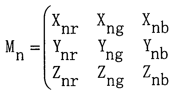
今、 n番目のディスプレイ装置を示す添え字 nを付加して、 式 1の行 列について、 以下の式 3, 式 4, 式 5に示すように定義する。 Now, the suffix n indicating the n-th display device is added, and the matrix of Equation 1 is defined as shown in Equations 3, 4, and 5 below.
式 3 Equation 3
X nrc X nrc
Ync Ync
7 7
、 ncノ , Nc
式 3は、 n番目のディスプレイの色 Cの XY Z三刺激値のマトリタス 表示の定義である。 Equation 3 defines the Matrix display of the XYZ tristimulus value for color C on the nth display.
式 4 Equation 4
式 4は、 n番目のディスプレイの R, G, B三原色の XYZ三刺激値 のマトリクス表示の定義である。 Equation 4 defines the matrix display of the XYZ tristimulus values of the R, G, and B primary colors on the nth display.
式 5 Equation 5
式 5は、 n番目のディスプレイの各原色単独の最大発光輝度に対する 比 (光の強さを表すスカラー量) のマ ト リクス表示の定義である。 Equation 5 defines the matrix display of the ratio (scalar quantity representing the light intensity) to the maximum emission luminance of each primary color of the n-th display alone.
以上のように定義すると、 n番目のディスプレイ装置のある色 Cn の XYZ三刺激値は、 式 6に示すように表わされる。 When defined as above, the XYZ tristimulus values of a certain color Cn of the nth display device are expressed as shown in Equation 6.
式 6は、 式 1を式 3, 式 4, 式 5で定義したマ トリ クス表示で表現し た式である。 式 6において、 "·" は行列の積を表す (以下、 同様) 。 式 6 Equation 6 is an expression that expresses Equation 1 in the matrix display defined by Equations 3, 4, and 5. In Equation 6, "·" represents the product of matrices (the same applies hereinafter). Equation 6
Cn =Mn -Dn C n = M n- D n
式 6より、 Mn は入力信号の R, G, Bのディジタル値から色の X YZ三刺激値への変換行列を表わすと言える。 入力信号が等しくても、 各ディスプレイ装置によって表示される色が異なる時には、 この行列 M n は、 各ディスプレイ装置に固有のものである。 From Equation 6, it can be said that M n represents a conversion matrix from the digital values of R, G, and B of the input signal to XYZ tristimulus values of the color. This matrix M n is specific to each display device when the input signals are equal but the colors displayed by each display device are different.
今、 式 6で表わされた色 Cn の値は、 実際、 各ディスプレイ装置毎 に異なるので、 プロジェクタュニットに入力する信号値に補正をかけて 最終的に表示される色、 つまり、 XYZ三刺激値がほぼ等しくなるよう にしたい。 そこで、 色処理部 8において、 入力信号に色変換係数 Mn t をかけて色変換を施し、 共通色再現領域の色を出力することを式 7に示 す。 式 7は、 ある色の各原色単独の最大発光輝度に対する比 (光の強さ を表すスカラー量) に色変換係数 Mn tをかけて、 共通色再現領域の色 (ターゲット色) に変換することを示した式である。 今、 共通色再現領 域の XYZ三刺激値を c t で表わす。 Now, since the value of the color C n expressed by Equation 6 actually differs for each display device, the signal value input to the projector unit is corrected and the color finally displayed, that is, XYZ I want the tristimulus values to be almost equal. Equation 7 shows that the color processing unit 8 performs color conversion by multiplying the input signal by the color conversion coefficient Mnt and outputs a color in the common color reproduction area. Equation 7 shows that the ratio (scalar amount indicating light intensity) of each primary color to the maximum emission luminance of each primary color alone is multiplied by the color conversion coefficient M nt to convert it into the color (target color) of the common color reproduction area. Is an expression showing Now, representing the XYZ tristimulus values of the common color reproduction area in c t.
式 7 Equation 7
Ct =Mn -Mnt -Dn C t = M n- M nt- D n
本発明におけるカラーキヤリブレーションでは、 色変換係数 Mn tを 求め、 色処理部 8に格納する。 In the color calibration according to the present invention, a color conversion coefficient M nt is obtained and stored in the color processing unit 8.
さて、 Mn tは式 7において、 R, G, Bの三原色について考えたと
きに最も簡単に算出できる。 三原色 R, G, Bをそれぞれ別個に表示し た時の各原色単独の最大発光輝度に対する比を D とすると、 Dn , は、 式 8のように単位行列として表される。 Now, Mnt considers the three primary colors R, G, and B in Equation 7. Can be calculated most easily. Assuming that the ratio of each primary color to the maximum emission luminance when each of the three primary colors R, G, and B is displayed separately is D, D n , is expressed as a unit matrix as shown in Equation 8.
式 8 Equation 8
ノNo
式 8は、 式 5を拡張して三原色 R, G, Bをそれぞれ別個に表示した 時の各原色単独の最大発光輝度に対する比を示す式である。 Equation 8 is an equation that shows the ratio of each primary color to the maximum emission luminance when the three primary colors R, G, and B are separately displayed by extending Equation 5.
f r (Rr ) , f g (Gr ) , f b (B r ) は、 原色 Rを表示した 時の最大発光輝度に対する比である。 f r (Rg ) , f g (Gg ) , f b (B g ) は、 原色 Gを表示した時の最大発光輝度に対する比であ る。 f r (Rb ) , f g (Gb ) , f b (Bb ) は、 原色 Bを表示し た時の最大発光輝度に対する比である。 この式 8を用いると、 即ち、 D n ' が単位行列である場合を用いると、 式 7の共通色再現領域の XY Z三刺激値 C t が式 9のように表せる。 f r (R r ), f g (G r ), and f b (B r ) are ratios to the maximum emission luminance when the primary color R is displayed. f r (R g ), f g (G g ), and f b (B g ) are ratios to the maximum emission luminance when the primary color G is displayed. f r (R b ), f g (G b ), and f b (B b ) are ratios with respect to the maximum emission luminance when the primary color B is displayed. Using this equation 8, that is, using the case where D n ′ is a unit matrix, the XYZ tristimulus value C t of the common color reproduction area of equation 7 can be expressed as in equation 9.
式 9 Equation 9
Xtr tb 0 0、 X tr tb 0 0,
Xtg X X tg X
M 0 1 0 =M ct= Ytr Ytg Ytb n ·Μ nt D n M n ·Μ nt n ·Μ ntM 0 1 0 = M c t = Y tr Y tg Y tb n ・ Μ nt D n M n ・ Μ nt n
Z+ 0 0 1 Z + 0 0 1
Ztg Ztb Z tg Z tb
式 9は、 式 7を式 8同様に三原色 R, G, Bをそれぞれ別個に表示し た場合に拡張した式である。 最終的に求めたい Mn tは、 式 9を変換す ることにより、
式 1 0 Equation 9 is an extension of Equation 7 when the three primary colors R, G, and B are displayed separately, as in Equation 8. The Mnt that is finally obtained is obtained by transforming Equation 9. Equation 1 0
Mnt=Mn_1 -Ct となる。 式 1 0において、 "Mn 1 " は、 行列 Mn の逆行列を表す。 この式 1 0が最終的に求めたい色変換係数 Mn tを算出する式となる。 なお、 各原色単独の最大発光輝度を用いない場合には、 Dn は単位 行列で表せないので、 式 8の各要素の値を具体的に求める。 この場合、 式 1 0は、 Mn t =Mn— 1 · C t · Dn , 1となる。 ここで、 "Dn , _1" は、 行列 Dn , の逆行列を表す。 M nt = M n _1 - C t. In Equation 10, “M n 1 ” represents the inverse of the matrix M n . This equation 10 is an equation for calculating the color conversion coefficient Mnt desired to be finally obtained. When the maximum emission luminance of each primary color alone is not used, D n cannot be represented by a unit matrix, and thus the values of the respective elements of Equation 8 are specifically obtained. In this case, Equation 10 becomes M nt = M n — 1 · C t · D n , 1 . Here, “D n , _1 ” represents an inverse matrix of the matrix D n ,.
以上のように、 カラーキャリブレーションとは、 このシステムにおい て、 色処理部における色変換係数 Mn tを求めることである。 以下、 シ ステム制御部 6が実行するカラーキヤリブレーションの方法について、 図 2, 図 3のフローチャートをもとに詳細に述べる。 As described above, the color calibration is to determine the color conversion coefficient Mnt in the color processing unit in this system. Hereinafter, the color calibration method executed by the system control unit 6 will be described in detail with reference to the flowcharts of FIGS.
通常の映像表示の場合には、 色処理部 8において色変換を行うが、 力 ラーキヤリブレーションの際には色変換を行わずに表示を行うので、 各 色処理部 8に対して、 色変換なしの設定を行う (S 1 0) 。 In the case of normal image display, color conversion is performed in the color processing unit 8, but in the case of power calibration, display is performed without performing color conversion. Perform the setting without conversion (S10).
次に、 測色であるが、 例えば、 画面一面に黒 (BK) と原色の R, G , Bを順番に表示する。 ここで、 黒 (BK) を表示するのは、 後述する 黒浮き現象を考慮するためであり、 黒浮き現象を考慮しないのならば、 黒 (BK) を表示する必要はない。 Next, for colorimetry, for example, black (BK) and the primary colors R, G, and B are sequentially displayed on the entire screen. Here, the reason why black (BK) is displayed is to consider a black floating phenomenon described later. If the black floating phenomenon is not considered, it is not necessary to display black (BK).
それぞれの入力信号値 (Rd , Gd , Bd ) は、 Each input signal value (R d , G d , B d ) is
BK : (0, 0, 0) BK: (0, 0, 0)
R : (255, 0, 0) R: (255, 0, 0)
G : (0, 255, 0) G: (0, 255, 0)
B : (0, 0, 255) B: (0, 0, 255)
である。 まず、 黒 (BK) を全てのディスプレイ装置上に同時に表示し
、 色度センサ 4で得られた全てのディスプレイ装置の XY Z三刺激値を 色変換係数演算部 7に転送する。 色変換係数演算部 7では、 複数回のセ ンサの XY Z三刺激値を記憶しておき、 m回測定終了後に全てのディス プレイ装置の XY Z三刺激値の平均値をそれぞれ計算する (S I 1〜S 1 5) 。 計算された値は、 後述する黒浮き現象を考慮する場合に用いら れる。 また、 以上の処理を R, G, B原色全てについて行い (S 2 1〜 S 2 5 , S 3 1〜S 3 5, S 4 1〜S 4 5) 、 R, G, Bに対して式 4 の Mn が求められる。 求めた Mn は、 色変換係数 Mn tを求める式 1 0 に用いられる。 It is. First, display black (BK) on all display devices simultaneously. Then, the X, Y, and Z tristimulus values of all the display devices obtained by the chromaticity sensor 4 are transferred to the color conversion coefficient calculator 7. The color conversion coefficient calculator 7 stores the XYZ tristimulus values of a plurality of sensors, and calculates the average of the XYZ tristimulus values of all the display devices after the measurement is completed m times (SI 1 to S15). The calculated value is used when considering a black floating phenomenon described later. The above processing is performed for all the R, G, and B primary colors (S 21 to S 25, S 31 to S 35, S 41 to S 45). Mn of 4 is required. The obtained Mn is used in the expression 10 for obtaining the color conversion coefficient Mnt .
次に、 色変換係数演算部 7においてターゲット色の設定を行う (S 5 Next, the target color is set in the color conversion coefficient calculator 7 (S5).
0) 。 この時、 設定の方法として全ての測色値の中で、 それぞれの代表 色に対して、 例えば、 ここでは、 原色に対して、 彩度の最も小さい測色 値の XY Z三刺激値の値をターゲッ ト色の XY Z三刺激値 ct として 設定する。 彩度の最も小さな測色値の決定方法は、 3次元空間である X Y Z空間中の複数の点と直線で表される無彩色軸との距離をそれぞれ求 め、 最も小さな距離である測色値を選択する。 0). At this time, as a setting method, among all the colorimetric values, for each representative color, for example, here, for the primary color, the value of the XYZ tristimulus value of the colorimetric value with the smallest saturation the set as target color XY Z tristimulus values c t of. The method for determining the colorimetric value with the smallest saturation is to determine the distance between a plurality of points in the XYZ space, which is a three-dimensional space, and the achromatic axis represented by a straight line. Select
また、 上記の 3次元空間内での処理は複雑になるので、 以下に示すよ うに、 2次元平面に射影することで簡単な処理にできる。 但し、 近似で ある。 2次元平面への射影は、 例えば、 式 1 1で示す x, y色度座標へ の変換で表される。 例えば、 ディスプレイ装置 nの代表色 (原色) Rの XY Z三刺激値は (Xn r, Yn r, Z n r) で表わされるとすると、 この 値を色度座標 (x n r, y n r, z n r) で表わすと、 式 1 1のようになる 式
xnr =Xnノ(Xnr +Ynr +Znr) Also, since the above processing in the three-dimensional space is complicated, simple processing can be performed by projecting it on a two-dimensional plane as shown below. However, it is an approximation. The projection onto the two-dimensional plane is represented, for example, by conversion to x, y chromaticity coordinates shown in Equation 11: For example, assuming that the XYZ tristimulus value of the representative color (primary color) R of the display device n is represented by ( Xnr , Ynr , Znr ), this value is represented by the chromaticity coordinates ( xnr , ynr , znr). ) x nr = X n no ( X nr + Y nr + Z nr)
ynr =Ynノ(Xnr +Ynr +Znr) ynr = Y n ( X nr + Y nr + Z nr)
z =1— x ― z = 1— x ―
nr nr J nr nr nr J nr
式 1 1は、 x + y + z = 1という単位面への投影といえる。 この色度 座標系において、 無彩色軸も 1つの点となり、 2変数で表される。 その 座標を (x Q , y。 ) と表すと、 測色値の中で最も彩度の小さな値は 、 無彩色の点からの距離が最小の測色値である。 式で表わすと、 式 1 2 で算出される値が最小であるところの色度座標 (x n r, y n r) の点を ターゲット色の色度座標とする。 Equation 11 can be said to be a projection onto a unit plane of x + y + z = 1. In this chromaticity coordinate system, the achromatic axis is also one point and is represented by two variables. If the coordinates are expressed as (x Q , y.), The smallest value of the colorimetric values is the colorimetric value with the smallest distance from the achromatic point. When expressed by the equation, the point of the chromaticity coordinates (x nr , y nr ) where the value calculated by the equation 12 is the minimum is defined as the chromaticity coordinates of the target color.
式 1 2 Equation 1 2
1 = (xnr- 0)2 +(ynr-y0)2 但し、 このままでは、 XYZ三刺激値 (Xt r, Yt r, Z t r) がー意 には決まらない。 そこで、 XYZ三刺激値の内、 Yの値を設定すること にする。 その 1つの方法としては、 式 1 2で算出される値が最小である ディスプレイ nの (x n r, y„ r) の Yn rをそのまま採用し、 Xn r, Z n rの値を算出する。 1 = (x nr-0 ) 2 + (y nr- y 0 ) 2 However, the XYZ tristimulus values (X tr , Y tr , and Z tr ) cannot be determined at all. Therefore, among the XYZ tristimulus values, the value of Y is set. As one of the methods, the value of X nr , Z nr is calculated by directly using Y nr of (x nr , y „ r ) of the display n having the minimum value calculated by Equation 12.
これを原色 G, Bについても同様に行い、 それぞれの原色のターゲッ ト色の XYZ三刺激値 (Xt g, Yt g, Z t g) 、 (Xt b, Yt b, ztb ) を求める。 以上のことを 3次元空間で図示するのは困難であるので、 簡単のために 2次元の X y色度図上で示すと、 図 4のようになる。 This primary colors G, similarly performed for B, the target color of the XYZ tristimulus values of each primary color (X tg, Y tg, Z tg), determine the (X tb, Y tb, z tb). Since it is difficult to illustrate the above in a three-dimensional space, it is shown in FIG. 4 on a two-dimensional xy chromaticity diagram for simplicity.
また、 図 4は、 簡単のため 3つのディスプレイ装置についての例であ り、 左側が測色結果を示し、 右側に決定されたターゲット色の色度座標 が黒点會で示されている。 例えば、 黒点參は、 3つのディスプレイ装置 の原色 Rの測色値 R l, R 2 , R 3の中で最の彩度の小さな R 3がター ゲット色の色度座標となることを示している。
また、 その他のターゲット色の設定の方法として以下の方法もある。 n個の全てのディスプレイ装置の測色結果の XYZ三刺激値から、 それ ぞれの代表色に対して平均値 (即ち、 重心) となる値を算出し、 それを ターゲット色の XY Z三刺激値として設定する。 例えば、 ディスプレイ 装置 nの代表色 Rの X Y Z三刺激値は (Xn r, Yn r, Zn r) で表わさ れるとすると、 原色 Rのターゲット色の XY Z三刺激値 (Xt r, Y t r , Z t r) は、 式 1 3のようになる。 FIG. 4 shows an example of three display devices for the sake of simplicity. The left side shows the colorimetric results, and the right side shows the chromaticity coordinates of the determined target color in black dots. For example, the black dot reference indicates that among the colorimetric values Rl, R2, and R3 of the primary colors R of the three display devices, R3 having the smallest saturation is the chromaticity coordinates of the target color. I have. Also, there is the following method for setting other target colors. From the XYZ tristimulus values of the colorimetric results of all n display devices, calculate the value that is the average value (that is, the center of gravity) for each representative color, and calculate it as the XYZ tristimulus of the target color. Set as a value. For example, XYZ tristimulus values of the representative color R of the display device and n (X nr, Y nr, Z nr) When expressed by the target color XY Z tristimulus values of the primary colors R (X tr, Y tr, Z tr ) is as shown in Equation 13.
式 1 3 Equation 1 3
式 1 3は、 全てのディスプレイの代表色 Rの XY Z三刺激値の平均値 Equation 13 is the average of the X, Y, and Z tristimulus values for the representative color R of all displays.
(即ち、 重心) を算出する式である。 (That is, the center of gravity).
この計算を原色 G, Bについても同様に行い、 それぞれの原色のター ゲット色の XYZ三刺激値 (X t g, Yt g, Z t g) 、 (X t b, Yt b, Z t b) を求める。 以上のことを 3次元空間で図示するのは困難である ので、 簡単のために 2次元の X y色度図上で示すと、 図 5のようになる また、 図 4と同様、 図 5も簡単のため 3つのディスプレイ装置につい ての例であり、 左側が測色結果を示し、 右側に決定されたターゲット色 の色度座標が黒点 で示されている。 例えば、 Rの黒点秦は、 3つのデ イスプレイ装置の原色 Rの測定値 R 1, R 2 , R 3の平均値 (重心) を 示している。
9 This calculation primary colors G, similarly performed for B, the target color of the XYZ tristimulus values of each primary color (X tg, Y tg, Z tg), determine the (X tb, Y tb, Z tb). Since it is difficult to illustrate the above in a three-dimensional space, the two-dimensional xy chromaticity diagram shown in Fig. 5 for simplicity is as shown in Fig. 5. For simplicity, this is an example of three display devices. The left side shows the colorimetric results, and the right side shows the chromaticity coordinates of the determined target color with black dots. For example, the sunspot Hata of R indicates the average value (center of gravity) of the measured values R1, R2, and R3 of the primary colors R of the three display devices. 9
17 各原色 R, G, Bのターゲッ ト色の三刺激値 C t が決定すると、 色 変換係数演算部 7において、 それぞれのプロジェクタュニットに対する 色変換係数 Mn tが式 1 0に基づいて算出される (S 5 1 ) 。 この時、 実際は黒浮きの現象を考慮することが必要となる。 黒浮きとは、 デイジ タル入力信号値 R = G==B = 0を入力しても、 即ち、 黒 (BK) を表示 する場合でも、 実際は暗電流等によりわずかに発光することを言う。 17 each of the primary colors R, G, the target color tristimulus value C t and B is determined, the color conversion coefficient computing unit 7, a color conversion coefficient M nt for each projector Interview knit is calculated based on Equation 1 0 (S51). At this time, it is actually necessary to consider the phenomenon of black floating. Black floating means that even if a digital input signal value of R = G = = B = 0 is input, that is, even if black (BK) is displayed, light emission actually occurs due to dark current or the like.
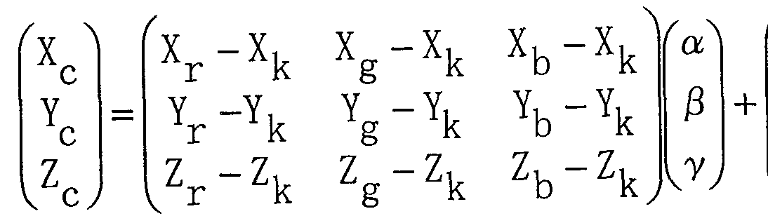
黒浮きの効果を考慮した場合、 式 1は式 1 4で示される式となる。 In consideration of the effect of the floating black, Equation 1 is represented by Equation 14:
式 1 4 Equation 1 4
式 1 4は、 暗電流による黒浮きの効果を考慮した時の色 Cの XYZ三 刺激値を示す式 1である。 即ち、 三原色の R, G, Bの混色により得ら れる色 Cの X Y Z三刺激値 X e , Y„ , Z e は、 三原色の R, G, B それぞれの XY Z三刺激値から暗電流の ΧΥ Ζ三刺激値 X Υ Equation 14 is an equation 1 showing the XYZ tristimulus values of the color C when the effect of the black floating due to the dark current is considered. That is, the three primary colors R, G, XYZ tristimulus values X e mixed by color C are obtained these B, Y ", Z e is the three primary colors R, G, and B the dark current from each of the XY Z tristimulus values Ζ ΖTristimulus value X Υ
Z k を引いた値の線形和であることを表した式である。 ここで、 α, β, γは、 光の強さを表わすスカラー量として、 式 1 5のように表わせ る。 式 1 5において、 R G B d は、 8ビッ トで表される R,This is an expression showing that it is a linear sum of values obtained by subtracting Zk. Here, α, β, and γ can be expressed as Expression 15 as scalar quantities representing light intensity. In Equation 15, RGB d is R, represented by 8 bits.
G, Bのディジタル入力信号である。 Y (Rd ) , Y (Gd ) , Y ( B d ) は、 暗電流による黒浮きの効果を考慮した時の各原色単独の発 光輝度である。 Yk は、 黒 (BK) を表示した場合の暗電流による発 光輝度である。 Yr , Yg , Yb は、 各原色単独の最大発光輝度であ る。 また、 式 1 5は、 式 2における関数 i r , f f h が 1次関数 で表すことができる光学デバイスについて考えるものとしている, 式 1 5
o; = (Y(R(1)-Yk)/(Yr-Yk) = Rd/255 G and B digital input signals. Y (R d ), Y (G d ), and Y (B d ) are the emission luminances of the primary colors alone when the effect of floating black caused by dark current is considered. Y k is the emission luminance due to dark current when displaying black (BK). Y r , Y g , and Y b are the maximum emission luminances of the primary colors alone. Equation 15 considers an optical device in which the functions i r and ff h in Equation 2 can be expressed by a linear function. o; = (Y (R (1 ) -Y k ) / (Y r -Y k ) = R d / 255
j3 = (Y(Gd)-Yk)/(Yg-Yk) = Gd/255 j3 = (Y (G d ) -Y k ) / (Y g -Y k ) = G d / 255
7 = (Y(Bd)-Yk)/(Yb-Yk) = Bd/255 7 = (Y (B d ) -Y k ) / (Y b -Y k ) = B d / 255
ここで、 喑電流による黒浮きの効果を考慮した時の各原色単独の発光 輝度 Y (Rd ) , Y (Gd ) , Y (B d ) は、 先に示したとおり、 式 2における関数 f r , f g , f b が 1次関数で表すことができる光学 デバイスについて考えるものとすると、 式 1 6で表わされる。 Here, the emission luminances Y (R d ), Y (G d ), and Y (B d ) of each primary color alone when the effect of the black floating due to the current is taken into account are calculated by the function in Equation 2 as described above. If we consider an optical device in which f r , f g , and f b can be expressed by linear functions, this is expressed by Equation 16:
式 1 6 Equation 1 6
. k k . k k
、、 ί, , Ί,
Y(Rd)、 (Yr-Yk)- d/255 Λ f Y (R d ), (Y r -Y k ) -d / 255 Λ f
Y(Gd) (Yg-V'V255 + γ, Y (G d ) (Yg-V'V 255 + γ,
Y(Bd ( -ν·ν255 Y (B d (-ν · ν 255
式 1 6は、 暗電流による黒浮きの効果を考慮した時の各原色単独の発 光輝度 Y (Rd ) , Y (Gd ) , Y (Bd ) を算出する式である。 よ つて、 式 1 5は、 式 1 6から得られる暗電流による黒浮きの効果を考慮 した時の各原色単独の発光輝度 Y (Rd ) , Y (Gd ) , Y (Bd ) を用いた場合の R, G, Bのディジタル入力信号から光の強さを表すス カラー量 α, β , y (各原色単独の最大発光輝度に対する比) を算出す る式である。 通常の C RTモニタやプロジェクタの場合、 式 1 5は式 1 7で表わされる。 Equation 16 is an equation for calculating the emission luminances Y (R d ), Y (G d ), and Y (B d ) of each primary color alone in consideration of the effect of floating black due to dark current. Thus, Equation 15 gives the emission luminances Y (R d ), Y (G d ), and Y (B d ) of each primary color alone, taking into account the black floating effect due to the dark current obtained from Equation 16 This equation is used to calculate the scalar quantities α, β, and y (the ratio of each primary color to the maximum emission luminance) representing the light intensity from the R, G, and B digital input signals when used. In the case of a normal CRT monitor or projector, Equation 15 is expressed by Equation 17.
式 1 7 Equation 1 7
a = (fr(Rd)-Yk)/(Yr-Yk) a = (f r (R d ) -Y k ) / (Y r -Y k )
^(fg(Gd)-Yk)/(Yg-Yk) ^ (f g (G d ) -Y k ) / (Y g -Y k )
= (fb(Bd)-Yk)/(Yb-Yk) = (f b (B d ) -Y k ) / (Y b -Y k )
式 1 7は、 発光輝度が 1次関数で表され得ない CRTモニタやプロジ ェクタの場合の光の強さを表すスカラー量 α, β , γ (各原色単独の最 大発光輝度に対する比) を表した式である。
式 1 5, 式 1 6, 式 1 7は、 式 1 4の中の α, β , γを説明するため のものである。 黒浮き現象を考慮する場合も、 α, β, yが式 1 5で表 されれば、 式 2の後の記述にあるように、 「ディジタル値 0〜 2 5 5の 値をとり得る入力信号について、 単純に 25 5で割ってノーマライズす ることで、 α, β, γを考えることにする」 という考え方で式 8, 式 9 を経て、 式 1 0に迪り着くことができる。 Equation 17 gives the scalar quantities α, β, and γ (ratio of each primary color to the maximum emission luminance) that represent the light intensity in the case of a CRT monitor or projector where the emission luminance cannot be expressed by a linear function. This is the expression shown. Equation 15, Equation 16 and Equation 17 are for explaining α, β, and γ in Equation 14. Even when the black floating phenomenon is considered, if α, β, and y are expressed by Equation 15, as shown in the description after Equation 2, the “input signal that can take a digital value of 0 to 255” By simply dividing by 255 and normalizing it, α, β, and γ will be considered. ”With the concept of“ Equation 8 ”and“ Equation 9 ”, it is possible to arrive at Equation 10.
暗電流による黒浮きの効果を考慮した時の求める色変換係数 M n tは 、 式 1 8で定義される変換行列 Mn と、 式 1 9で定義されるターゲッ ト色の X Y Z三刺激値 C t により、 式 1 0、 即ち、 Mn t=Mn— 1 · C t で求められる。 The color conversion coefficient M nt obtained in consideration of the effect of black floating due to dark current is represented by a conversion matrix M n defined by Equation 18 and a XYZ tristimulus value C t of the target color defined by Equation 19 Is given by Equation 10, that is, M nt = M n — 1 · C t .
式 1 8 Equation 1 8
,Xnr - Xnk Xng"Ank Xnb- Xnk , X nr- X nk X ng " A nk X nb- X nk
γ — γ Y - Y γ — γ Y-Y
Mn = nr nk ng nk Ynb"Ynk M n = nr nk ng nk Y nb " Y nk
Z nr一 Z n ,k Z ng一 Z n ,k Znb— Znk Z nr one Z n, k Z ng one Z n, k Z nb- Z nk
式 1 9 Equation 1 9
Xtr "Xtk Xtg "Xtk Xtb — ¾ X tr " X tk X tg" X tk X tb — ¾
Ytr — ¾ Ytg "Ytk Ytb ~Ytk Y tr — ¾ Y tg " Y tk Y tb ~ Y tk
Ztr -Ztk Ztg "Ztk Ztb ~Ztk Z tr- Z tk Z tg " Z tk Z tb ~ Z tk
式 1 8は、 暗電流による黒浮きの効果を考慮した時の式 4の定義、 即 ち、 n番目のディスプレイの R, G, B三原色の X Y Z三刺激値のマト リクス表示の定義である。 式 1 8において、 Xn k, Yn k, Zn kは、 n 番目のディスプレイに黒 (BK) を表示した場合の XYZ三刺激値であ る。 また、 式 1 9は、 暗電流による黒浮きの効果を考慮した時の式 9の 定義、 即ち、 R, G, B三原色のターゲット色の XY Z三刺激値のマト リクス表示の定義である。 式 1 9において、 X t k, Y t k, Z t kは、 タ ーゲット色の黒の XY Z三刺激値である。
ここで、 ターゲッ ト色の黒の X Y z三刺激値 (X t k, Y t k, z t k) としては、 各ディスプレイ装置の黒の XYZ三刺激値 (Xn k, Yn k, Zn k) の中で、 最も大きな Yn kを持つ XYZ三刺激値を選択する。 なお、 Dn ' が単位行列で表せない場合、 式 9は C t =Mn - Mn t · Dn ' となるので、 式 1 0は Mn t=Mn一 1 · C t · Dn , —1となる 。 ここで、 "Dn ' — は、 行列 Dn ' の逆行列を表す。 Equation 18 is the definition of Equation 4 when considering the effect of black floating due to dark current, that is, the definition of the matrix display of the XYZ tristimulus values of the R, G, and B primary colors on the nth display. In Equation 18, X nk , Y nk , and Z nk are XYZ tristimulus values when black (BK) is displayed on the nth display. Equation 19 is the definition of Equation 9 in consideration of the effect of black floating due to dark current, that is, the definition of the matrix display of the XYZ tristimulus values of the target colors of the R, G, and B primary colors. In Equation 19, Xtk , Ytk , and Ztk are the XYZ tristimulus values of the target color black. Here, XY z tristimulus values of black target color (X tk, Y tk, z tk) as the black XYZ tristimulus values of the display devices (X nk, Y nk, Z nk) in Select the XYZ tristimulus value with the largest Y nk . If D n ′ cannot be represented by an identity matrix, Equation 9 becomes C t = M n −M nt · D n ′, and thus Equation 10 becomes M nt = M n− 1 · C t · D n , — Becomes 1 . Where "D n '— represents the inverse of matrix D n '.
求められた各ディスプレイ装置の色変換係数 Mn tは、 各ディスプレ ィ装置の色処理部 8に格納され (S 5 2) 、 テス ト画像を表示して (S 5 3) 、 カラーキャリブレーションモードを終了する。 The obtained color conversion coefficient Mnt of each display device is stored in the color processing unit 8 of each display device (S52), a test image is displayed (S53), and the color calibration mode is set. finish.
この実施の形態によれば、 全てのディスプレイ装置において、 前記代 表色を目的とするターゲット色になるように、 カラーキヤリブレーショ ンすることができる。 また、 この実施の形態によれば、 複数のディスプ レイ装置の表示色を測色することにより、 ターゲット色を自動的に求め ることができる。 According to this embodiment, in all display devices, color calibration can be performed so that the target color is the target color. Further, according to this embodiment, the target color can be automatically obtained by measuring the display colors of the plurality of display devices.
また、 この実施の形態によれば、 複数のディスプレイ装置の色を測色 する色度センサをマルチビジョンシステム内に内蔵し、 複数のディスプ レイ装置の間の非表示エリアに色度センサを設置し、 直接光源からの光 を測色するので、 装置を大型化せずにカラーキヤリブレーション装置を 設けることができる。 Further, according to this embodiment, a chromaticity sensor for measuring colors of a plurality of display devices is built in the multi-vision system, and the chromaticity sensor is installed in a non-display area between the plurality of display devices. However, since the color from the light source is directly measured, a color calibration device can be provided without increasing the size of the device.
また、 この実施の形態によれば、 各代表色につき複数ディスプレイ装 置の測色値の中で彩度の最も小さい測色値をその代表色のターゲット色 し、 前記ターゲット色を自動的に設定するので、 彩度の点では厳密な力 ラーキヤリブレーションを自動的に行うことができ、 単純に共通色再現 領域だけを追及していった時に、 色再現領域が狭くなってしまうという 問題を解決できる。 Further, according to this embodiment, for each representative color, the colorimetric value having the smallest saturation among the colorimetric values of a plurality of display devices is set as the target color of the representative color, and the target color is automatically set. Chromatic calibration can be performed automatically in strict terms in terms of saturation, and the problem that the color reproduction area becomes narrower when simply pursuing only the common color reproduction area Solvable.
また、 この実施の形態によれば、 各代表色につき、 複数ディスプレイ
装置の測色値の平均値をその代表色のターゲッ ト色とし、 前記ターゲッ ト色を自動的に設定するので、 カラーキヤリブレーションを自動的に行 うことができ、 単純に共通色再現領域だけを追及していった時に、 色再 現領域が狭くなってしまうという問題を解決できる。 According to this embodiment, a plurality of displays are provided for each representative color. Since the average value of the colorimetric values of the device is set as the target color of the representative color and the target color is automatically set, the color calibration can be automatically performed, and the common color reproduction area can be simply obtained. This solves the problem that the color reproduction area becomes narrower when pursuing only color.
また、 この実施の形態は、 ターゲッ ト色が予め定められていれば、 1 台のディスプレイ装置のカラーキヤリブレーションにも適用することが できる。 1台のディスプレイ装置のカラーキヤリブレーションを実行す る場合は、 色変換係数演算部 7が 3次元空間を用いて色変換係数を算出 することを特徴とする。 即ち、 色変換係数演算部 7が加法混色モデルに おける三原色の混色により得られる色の X Y Z三刺激値を用いて色変換 係数を算出することを特徴とする。 In addition, this embodiment can be applied to color calibration of one display device as long as the target color is determined in advance. When performing color calibration of one display device, the color conversion coefficient calculator 7 calculates color conversion coefficients using a three-dimensional space. That is, the color conversion coefficient calculation unit 7 calculates the color conversion coefficient using the XYZ tristimulus values of the colors obtained by mixing the three primary colors in the additive color mixture model.
実施の形態 2 . Embodiment 2
この発明の実施の形態 2を図に基づいて説明する。 Embodiment 2 of the present invention will be described with reference to the drawings.
図 6は、 本発明の一実施の形態を示すカラーキヤリブレーシヨン機能 を備えたマルチビジョンシステムの全体ブロック図である。 FIG. 6 is an overall block diagram of a multi-vision system having a color calibration function according to an embodiment of the present invention.
図 6において、 実施の形態 1 と異なる特徴は、 色度センサ 4がマルチ ビジョンシステムの外部に設置されていることである。 従って、 光源の 色ではなく、 スク リーンユニッ ト 3の色そのものを測色する。 また、 実 施の形態 1では、 スク リーンの外に漏れてくる光を測っていたが、 実施 の形態 2のこのシステムにおいては、 スク リーンの中央部の色を測るこ とができる。 キャリブレーションの方法は、 実施の形態 1に同じである この実施の形態によれば、 複数のディスプレイ装置の色を測色する色 度センサをマルチビジョンシステム外に設置するので、 光源からの光の 色ではなくディスプレイ装置の表示色そのものを測色でき、 また、 測色 の位置もディスプレイ装置の中央部に設定できるので、 より精密な測色
、 更には精密なカラーキヤリブレーションが可能になる。 In FIG. 6, a feature different from the first embodiment is that the chromaticity sensor 4 is installed outside the multi-vision system. Therefore, the color of the screen unit 3 itself is measured instead of the color of the light source. Further, in the first embodiment, the light leaking out of the screen is measured. However, in this system according to the second embodiment, the color at the center of the screen can be measured. The calibration method is the same as that of the first embodiment. According to this embodiment, a chromaticity sensor for measuring the colors of a plurality of display devices is installed outside the multi-vision system. The color of the display device itself can be measured instead of the color, and the position of the color measurement can be set at the center of the display device. In addition, precise color calibration becomes possible.
実施の形態 3. Embodiment 3.
この発明の実施の形態 3を図に基づいて説明する。 Embodiment 3 of the present invention will be described with reference to the drawings.
図 7は、 本発明の一実施の形態を示すカラーキヤリブレーション機能 を備えたマルチビジョンシステムの全体ブロック図である。 FIG. 7 is an overall block diagram of a multi-vision system having a color calibration function according to an embodiment of the present invention.
図 7において、 実施の形態 1 と異なる特徴は、 ディスプレイ装置の数 より少ない色度センサ 4がマルチビジョンシステムの外部に設置されて いることである。 この色度センサ 4は、 具体的に横 1列に並ぶディスプ レイ装置の数だけセンサュニッ ト 1 0上に 1ライン上に配置され、 セン サユニッ ト 1 0は、 図 7に示すように、 マルチビジョンに平行して Aの 方向に走査する機構 (図示せず) を備えている。 センサユニット 1 0は In FIG. 7, a feature different from the first embodiment is that chromaticity sensors 4 smaller than the number of display devices are installed outside the multi-vision system. The chromaticity sensors 4 are arranged in one line on the sensor unit 10 as many as the number of display devices arranged in one horizontal row, and the sensor unit 10 is, as shown in FIG. A mechanism (not shown) that scans in the direction of A in parallel with is provided. Sensor unit 10
、 マルチビジョン上を走査しながら、 上下方向に位置を変えて各スクリ ーンュニッ トの複数の点を測色する。 測色点を図 7の各スク リーンュニ ット 3上の X印で示す。 While scanning on the multi-vision, change the position in the vertical direction and measure multiple points on each screen unit. The colorimetric points are indicated by X marks on each screen unit 3 in FIG.
以下、 システム制御部 6の動作を、 図 8, 図 9のフローチャートに従 つて詳細に説明する。 Hereinafter, the operation of the system control unit 6 will be described in detail with reference to the flowcharts of FIGS.
各色処理部に色変換なしのモードを設定した後 (S 58) 、 まず、 セ ンサユニット 1 0の位置を初期化する (S 59) 。 最初に 1, 2, 3の スクリーンュニッ ト 3についての測色をするということで、 最上段の位 置設定を行う (S 6 1 ) 。 次に、 最初の測色点 K= 1のラインまでセン サユニッ ト 1 0を動かし、 固定する (S 62) 。 測色は、 実施の形態 1 と同様、 BK, R, G, Βの順に行い、 各色の映像信号を入力した後に 色度センサ 4より ΧΥ Ζ三刺激値をロードする。 以上のようにして、 1 回の測色が終了すると、 センサユニッ ト 1 0を、 また K= lのラインま で動かし、 固定して測色する。 これを Κ= 3のラインまで繰り返す (S 6 3〜S 6 6) 。 図の簡略化のため、 測色点は各スクリーンユニッ ト 3
JP /017 After setting the mode without color conversion in each color processing unit (S58), first, the position of the sensor unit 10 is initialized (S59). First, the uppermost position is set by performing colorimetry on screen units 3 of 1, 2, and 3 (S61). Next, the sensor unit 10 is moved to the first colorimetric point K = 1 line and fixed (S62). The colorimetry is performed in the order of BK, R, G, 同 様 as in the first embodiment, and the tristimulus values are loaded from the chromaticity sensor 4 after inputting the video signal of each color. As described above, when one color measurement is completed, the sensor unit 10 is moved to the line of K = l and fixed, and the color is measured. This is repeated until the line of ラ イ ン = 3 (S63 to S66). For simplification of the figure, the colorimetric points are JP / 017
23 にっき 4点となっているが、 これ以上でも以下でも良い。 以上のように 、 最上段のスク リーンユニッ ト 3の測色が終了すると、 それぞれのスク リーンュニッ ト 3の代表色の XYZ三刺激値から平均値を算出する (S 6 7) 。 同様の処理を中段、 最下段についても行い、 全てのスクリーン ュニッ ト 3の測色を終了する (S 7 1〜S 7 7, S 8 1〜S 8 7) 。 以 降のターゲッ ト色の算出、 色変換係数の算出等の処理は、 実施の形態 1 に同じである (S 50〜S 5 3) 。 23 Nikki 4 points, but more or less. As described above, when the color measurement of the uppermost screen unit 3 is completed, the average value is calculated from the XYZ tristimulus values of the representative colors of each screen unit 3 (S67). The same process is performed for the middle and bottom rows, and the colorimetry of all screen units 3 is completed (S71 to S77, S81 to S87). Subsequent processes such as calculation of the target color and calculation of the color conversion coefficient are the same as those of the first embodiment (S50 to S53).
この実施の形態によれば、 複数のディスプレイ装置の色を測色する色 度センサを、 マルチビジョンシステム外に 1ライン上のセンサュニッ ト 上に設置し、 センサユニッ トはマルチビジョンに平行に走査しながら、 全てのディスプレイ装置の表示色を測色するので、 ディスプレイ装置の 数より少ない色度センサで全てのディスプレイ装置の測色が可能になる 実施の形態 3においては、 センサの走査方向が 1次元で Aの方向のみ であるが、 マルチビジョンに平行、 かつ、 Aの方向に対して 90° の方 向の走査機構も持たせて、 2次元の走査を行ってもよい。 According to this embodiment, a chromaticity sensor for measuring the colors of a plurality of display devices is installed on a one-line sensor unit outside the multi-vision system, and the sensor unit scans while parallel to the multi-vision. However, since the display colors of all the display devices are measured, the colorimetry of all the display devices can be performed with less chromaticity sensors than the number of the display devices. In the third embodiment, the scanning direction of the sensor is one-dimensional. Although it is only in the direction of A, two-dimensional scanning may be performed by providing a scanning mechanism parallel to the multivision and at a direction of 90 ° to the direction of A.
また、 全ての測色点の測色値を平均して用いているが、 例えば、 1つ のスクリーンュニッ ト内の任意の位置の測色点を決めておき、 その 1点 のみの測色値を用いてもよい。 また、 任意の複数点の測色点の平均値を 用いてもよい。 In addition, the colorimetric values of all the colorimetric points are averaged and used.For example, a colorimetric point at an arbitrary position within one screen unit is determined, and the colorimetric value of only one point is determined. May be used. Alternatively, an average value of arbitrary colorimetric points may be used.
実施の形態 4. Embodiment 4.
この発明の実施の形態 4を図に基づいて説明する。 Embodiment 4 of the present invention will be described with reference to the drawings.
図 1 0は、 本発明の一実施の形態を示すカラーキヤリブレーション機 能を備えたマルチビジョンシステムの全体ブロック図である。 FIG. 10 is an overall block diagram of a multi-vision system having a color calibration function according to an embodiment of the present invention.
図 1 0において、 実施の形態 1 と異なる特徴は、 ターゲット色の設定 を行う際に、 原色 BK, R, G, Bの各スク リーンユニッ ト 3の測色値
( X Y Z三刺激値) をシステム制御部 6に接続しているディスプレイモ ニタ 1 1に 3次元座標 2 0を表示し、 オペレータは、 前記ディスプレイ モニタ 1 1で各スクリーンュニッ ト 3の測色結果を確認し、 マウス 1 2 などのポィンティングデパイスで各原色のターゲッ ト色をオペレータが 設定できることである。 In FIG. 10, the feature different from the first embodiment is that the colorimetric values of the screen units 3 of the primary colors BK, R, G, and B are used when setting the target color. (XYZ tristimulus values) are displayed on the display monitor 11 connected to the system controller 6 in three-dimensional coordinates 20. The operator checks the colorimetric results of each screen unit 3 on the display monitor 11 In addition, the operator can set the target color of each primary color with a pointing device such as mouse 12.
ターゲッ ト色の設定の方法を具体的に図 1 1を用いて説明する。 The method of setting the target color will be specifically described with reference to FIG.
図 1 1は、 システム制御部 6に接続しているディスプレイモニタ 1 1 の画面が 2つ示されている。 FIG. 11 shows two screens of the display monitor 11 connected to the system control unit 6.
左にはターゲッ ト色を決める前の段階の画面が、 右にはターゲッ ト色 を決めた後の段階の画面が示されている。 それぞれスク リーンユニット の測色結果が、 3次元座標 2 0上に示されている。 この 3次元座標は、 回転できるようになつている。 ここでは、 図の簡略化のため、 2つのス クリーンユニッ トの測色結果を表示している。 オペレータは、 この 3次 元座標 2 0上の測色結果を見て、 例えば、 全てのスク リーンユニッ トの 最大の共通色再現域となるように、 ターゲッ ト色を設定する。 Rのボタ ン 2 1をマウス 1 2でクリックすると、 3次元座標 2 0上には Rの文字 と黒点參が表示される。 オペレータは、 マウス 1 2を用いて、 この黒点 •を 3次元座標 2 0上で移動させることができる。 このとき、 1方向か らの 3次元表示では位置が分かりにくい場合、 回転ボタン 2 6をマウス 1 2でクリックすると、 座標系が回転するようになっている。 座標系の 表示パターンはいくつか存在し、 回転ボタンをクリックする度に、 次の 表示パターンに変化するようになっている。 また、 3次元空間内で 1点 を設定しづらいことがあれば、 ターゲッ ト色の X Y Z三刺激値は、 各ス クリーンュニッ トの 3つの代表色の測色値の点を結んでできる三角形の 辺、 頂点の上にのみ設定され得るという制限を設けてもよい。 The left shows the screen before the target color is determined, and the right shows the screen after the target color is determined. The colorimetric results of the respective screen units are shown on the three-dimensional coordinates 20. These 3D coordinates can be rotated. Here, the colorimetric results of two screen units are displayed for simplification of the figure. The operator looks at the colorimetric result on the three-dimensional coordinates 20 and sets, for example, a target color so as to be the maximum common color gamut of all the screen units. If you click the R button 21 with the mouse 12, the letter R and the black dot are displayed on the three-dimensional coordinates 20. The operator can move this black spot on the three-dimensional coordinates 20 using the mouse 12. At this time, if the position is difficult to understand in the three-dimensional display from one direction, click the rotation button 26 with the mouse 12 to rotate the coordinate system. There are several coordinate system display patterns, and each time you click the rotation button, it changes to the next display pattern. If it is difficult to set one point in the three-dimensional space, the target color XYZ tristimulus values can be calculated by using the sides of the triangle formed by connecting the points of the colorimetric values of the three representative colors of each screen unit. There may be a restriction that it can only be set on vertices.
オペレータがターゲッ ト色の χ γ z三刺激値の点に黒点譬を移動させ
た後、 選択ボタン 2 4をクリ ックすると、 Rのターゲッ ト色が黒点會の 座標値として決定される。 同様に、 G, Bについてもターゲッ ト色を決 定し、 終了ボタン 2 5をクリ ックすると、 ターゲッ ト色の X Y Z三刺激 値を頂点にした三角形が表示され、 オペレータは、 決定したターゲッ ト 色の確認ができる。 この状態を図 1 1の右の部分に示す。 これ以降の色 変換係数の算出等の処理は、 実施の形態 1に同じである。 The operator moves the black dot parallax to the point of the target color γγ z tristimulus value. Then, when the select button 24 is clicked, the target color of R is determined as the coordinate value of the black spot. Similarly, the target colors are determined for G and B, and when the end button 25 is clicked, a triangle having the XYZ tristimulus values of the target colors as vertices is displayed, and the operator determines the target colors determined. You can check the color. This state is shown in the right part of FIG. Subsequent processes such as calculation of the color conversion coefficient are the same as in the first embodiment.
なお、 オペレータによらず、 自動的にターゲット色を決定してもよい この実施の形態によれば、 全てのディスプレイ装置の色再現領域内で 、 共通の色再現域を最大にとれるようにターゲッ ト色を設定するので、 ターゲット色は全てのディスプレイ装置が表現可能な色となり、 厳密な カラーキヤリブレーションが可能となる。 Note that the target color may be automatically determined without depending on the operator. According to this embodiment, the target is set so as to maximize the common color gamut within the color gamut of all display devices. Because the colors are set, the target color is a color that can be expressed by all display devices, and strict color calibration is possible.
また、 この実施の形態によれば、 全てのディスプレイ装置の測色結果 を接続しているディスプレイモニタ上でオペレータが確認して、 ターゲ ッ ト色を決定するので、 多くのディスプレイ装置の共通色再現領域を最 大に設定することを目視で簡単に行うことができる。 Further, according to this embodiment, since the operator checks the colorimetric results of all display devices on the connected display monitor and determines the target color, the common color reproduction of many display devices is performed. It is easy to visually set the maximum area.
実施の形態 5 . Embodiment 5
この発明の実施の形態 5を図に基づいて説明する。 Embodiment 5 of the present invention will be described with reference to the drawings.
図 1 2は、 本発明の一実施の形態を示すカラーキヤリブレーション機 能を備えたマルチビジョンシステムの全体ブロック図である。 FIG. 12 is an overall block diagram of a multi-vision system having a color calibration function according to an embodiment of the present invention.
図において、 実施の形態 1と異なる特徴は、 ターゲッ ト色の設定を行 う際に、 このキャリブレーションが 2回目以降であれば、 以前に測色し た時の X Y Z三刺激値を参照し、 前回の X Y Z三刺激値と今回の X Y Z 三刺激値の値がかなり異なる場合であれば、 キヤリブレーションを実行 する。 In the figure, the feature that is different from the first embodiment is that, when setting the target color, if this calibration is performed for the second time or later, reference is made to the XYZ tristimulus values from the previous color measurement, If the values of the previous XYZ tristimulus value and the current XYZ tristimulus value are significantly different, execute calibration.
以下、 キャリブレーションの実行の決定のアルゴリズムを図 1 3, 図
1 4のフローチヤ一トに沿って示す。 The algorithm for determining the execution of calibration is described below. Shown along the flowchart of FIG.
図 1 3と図 1 4は、 S 46を除き、 図 2と図 3と同じである。 S 46 のキヤリブレーションを実行するか否かの判断は、 ターゲッ ト色の算出 FIGS. 13 and 14 are the same as FIGS. 2 and 3 except for S46. The determination of whether to execute the calibration in S46 is based on the calculation of the target color.
(S 50) の前に行う。 この判断の具体的な内容については、 図 1 5の フローチヤ一トに従って以下に示す。 まず、 メモリに記憶されている前回のカラーキヤリブレーション時の 原色の XY Z三刺激値において、 黒浮きを考慮したマトリクスを式 20 で表わされる Μη ,とする。 Perform before (S50). The specific contents of this judgment are shown below according to the flowchart of FIG. First, in the XY Z tristimulus values of the primary colors of the previous color Canon calibration stored in the memory, and Micromax eta, the matrix in consideration of the black floating of formula 20.
式 20 Equation 20
Mnl M nl
式 20は、 喑電流による黒浮きを考慮した場合の前回の n番目のディ スプレイの R, G, B三原色の XYZ三刺激値のマトリクス表示の定義 である。 Equation 20 is the definition of the matrix display of the XYZ tristimulus values of the R, G, and B primary colors of the previous n-th display, considering the black floating due to the 喑 current.
また、 前回のターゲッ ト色の ΧΥΖ三刺激値のマトリタスを式 2 1で 表わされる C t ,とする。 Also, let the matrix of the tristimulus value of the previous target color be C t , represented by Equation 21.
式 2 1 Equation 2 1
Xtrl - Xtkl Xtgl - Xtkl Xtbl一 X tkl X trl- X tkl X tgl- X tkl X tbl X tkl
-I -I
Ctl = Ytrl - Ytkl Hgl - Ytkl Ytbl tkl C tl = Y trl- Y tkl Hgl- Y tkl Y tbl tkl
Ztrl "Ztkl Ztgl — Ztkl "tbl一 tkl Z trl " Z tkl Z tgl — Z tkl" tbl one tkl
式 2 1は、 喑電流による黒浮きを考慮した場合の前回の R, G, B三 原色のターゲッ ト色の XY Z三刺激値のマトリクス表示の定義である。 また、 今回の測色における原色の XY Z三刺激値についての黒浮きを 考慮したマトリクス Mn を式 1 8、 ターゲッ ト色 C t を式 1 9で表わ す。
最初に、 前回の測色値と今回の測色値より Mn , _Mn を算出し、 そ れを DMnとし、 式 22で表わす。 Equation 21 defines the matrix display of the X, Y, and Z tristimulus values of the target color of the previous R, G, and B primary colors when the black floating due to the 喑 current is considered. Also, the matrix Mn in consideration of the floating of black for the XYZ tristimulus values of the primary colors in this colorimetry is expressed by Equation 18 and the target color Ct is expressed by Equation 19. First, M n, was calculated _M n from current colorimetric value and the previous colorimetric values, the Re its a D Mn, represented by the formula 22.
式 2 2は、 前回の測色結果より得られる式 2 0による Μη ,と、 今回 の測色結果により得られる式 1 8による Mn の差を定義した式である Equation 22 defines the difference between Μ η from Equation 20 obtained from the previous colorimetric result and M n from Equation 18 obtained from the current colorimetric result.
判断 1は、 条件 「全てのディスプレイ装置について、 マ トリクス DM nの要素の絶対値でしきい値 t h 1を超える要素が存在しない。 」 を満 たすかどうかを判断する。 式で表わすと、 式 23に示すようになる。 式 2 3 Decision 1, "for all of the display device, Ma Torikusu D M n elements exceeds the threshold th 1 in absolute value of the element does not exist in." Conditions plus whether to determine satisfy the. This can be expressed as shown in Equation 23. Equation 2 3
1J '<thl 1J '<thl
式 2 3は、 式 2 2のマトリタス DMnの要素の絶対値がしきい値 t h 1より小さいことを示す式である。 Equation 23 is an equation indicating that the absolute value of the element of Matritas D Mn in Equation 22 is smaller than the threshold th1.
判断 2は、 条件 「全てのディスプレイ装置について、 判断パラメータ P 1 としてマトリクス DMnの要素の絶対値の和を算出し、 それがしき い値 t h 2を超えない。 」 を満たすかどうかを判断する。 具体的に式で 示すと、 式 24に示すようになる。 Judgment 2 judges whether or not the condition “for all display devices, the sum of the absolute values of the elements of the matrix D Mn is calculated as the judgment parameter P 1 and it does not exceed the threshold value th 2.” . Specifically, the expression is as shown in Expression 24.
式 24 Pl =∑∑|dnij|≤th2 式 24は、 式 2 2のマトリクス DMnの要素の絶対値の和がしきい値 t h 2より小さいことを示す式である。 Equation 24 Pl = ∑∑ | d nij | ≤th2 Equation 24 is an equation indicating that the sum of the absolute values of the elements of the matrix D Mn in Equation 22 is smaller than the threshold th2.
判断 1、 判断 2の両方を満たした場合、 今回の測色結果は前回の測色
結果とほとんど変わらないと判断し、 カラーキヤリブレーションは実行 されない。 If both Judgment 1 and Judgment 2 are satisfied, the current colorimetry result will be Judging that the result is almost the same, the color calibration is not performed.
判断 3では、 条件 「式 23を満たさなかったディスプレイ装置の数が しきい値 t h 3を超えない。 」 を満たすかどうかを判断する。 ここで、 式 2 3を満たさなかったディスプレイ装置、 つまり、 ある程度変化の大 きかったディスプレイ装置の数が多かった場合には、 通常のキヤリブレ ーションを行う。 In the determination 3, it is determined whether or not the condition “the number of display devices that do not satisfy Expression 23 does not exceed the threshold value th3” is satisfied. Here, when the number of display devices that do not satisfy Expression 23, that is, the number of display devices that have changed to some extent is large, normal calibration is performed.
判断 4では、 条件 「式 24を満たさなかったディスプレイ装置の数が しきい値 t h 4を超えない。 」 を満たすかどうかを判断する。 ここで、 式 24を満たさなかったディスプレイ装置、 つまり、 ある程度変化の大 きかったディスプレイ装置の数が多かった場合には、 通常のキヤリブレ ーションを行う。 In the determination 4, it is determined whether or not the condition “the number of display devices that do not satisfy Expression 24 does not exceed the threshold value th4” is satisfied. Here, when the number of display devices that do not satisfy Expression 24, that is, the number of display devices that have changed to some extent is large, normal calibration is performed.
判断 5で前回のターゲッ ト色の X Y Z三刺激値と今回の測色値とを比 較するために、 C t l _Mn を算出し、 それを DCnとし、 式 2 5で表わ す。 In order to compare the XYZ tristimulus value of the previous target color with the current colorimetric value in decision 5, C tl _M n is calculated, and it is expressed as D Cn , which is expressed by equation 25.
式 25 nil cn21 "n31 Expression 25 nil c n21 "n31
DCn=Ctl一 Mn = c nl2 cn22 cn32 D Cn = C tl-M n = c nl2 c n22 c n32
Vcnl3 cn23 cn33ノ V c nl3 c n23 c n33
式 2 5は、 前回のターゲッ ト色の XYZ三刺激値のマトリクス C t l (式 2 1 ) と、 今回の測色結果の Mn (式 1 8) との差を定義した式 である。 Equation 25 is an equation that defines the difference between the matrix C tl (Equation 21 ) of the previous target XYZ tristimulus value of the target color and M n (Equation 18) of the current colorimetric result.
判断 5は、 条件 「全てのディスプレイ装置について、 判断パラメータ P 2としてマトリタス DCnの要素の絶対値の和を算出し、 それがしき い値 t h 5を超えない。 」 を満たすかどうかを判断する。 具体的に式で 示すと、
式 2 6 The judgment 5 judges whether or not the condition “for all display devices, the sum of the absolute values of the elements of the matrix D Cn is calculated as the judgment parameter P 2, and the sum does not exceed the threshold value th 5.” . In concrete terms, Equation 2 6
P2 =∑∑|cnij|≤th5 式 2 6は、 式 2 5のマトリタス D C nの要素の絶対値の和がしきい値 t h 5より小さいことを示す式である。 P2 = ∑∑ | c nij | ≤th5 Equation 26 is an equation that indicates that the sum of the absolute values of the elements of Matritas D Cn in Equation 25 is smaller than the threshold th5.
となる。 Becomes
判断 5で y e s となった場合、 カラーキヤリブレーションとしては、 式 2 3, 式 2 4, 式 2 6の全てを満たしたディスプレイ装置以外のディ スプレイ装置について、 カラーキャリブレーションを行う。 その時に、 ターゲッ ト色は前回の値 C t ,を用いて、 色変換係数の算出を行う。 この実施の形態によれば、 各ディスプレイ装置の測色値、 ターゲット 色の色度値をメモリに記憶し、 次回のキヤリブレーシヨンの際に得られ た測色値を前回の測色値、 又はターゲッ ト色の色度値と比較し、 ある程 度の差がある場合にのみキヤリブレーションを行うので、 不必要な処理 を行わなくて済む。 If the result of determination 5 is yes, color calibration is performed for display devices other than display devices that satisfy all of Equations 23, 24 and 26 as color calibration. At that time, the color conversion coefficient is calculated using the previous value C t , for the target color. According to this embodiment, the colorimetric value of each display device and the chromaticity value of the target color are stored in the memory, and the colorimetric value obtained at the next calibration is used as the previous colorimetric value, or Compared with the chromaticity value of the target color, calibration is performed only when there is a certain degree of difference, so that unnecessary processing is not performed.
また、 この実施の形態によれば、 各ディスプレイ装置の測色値、 ター ゲッ ト色の色度値をメモリに記憶し、 次回のキヤリブレーションの際に 得られた測色値を前回の測色値、 又はターゲッ ト色の色度値と比較し、 ある程度の差があるディスプレイ装置を自動的に選択し、 前記選択され たディスプレイ装置に限ってカラーキヤリブレーションを行うので、 不 必要な処理を行わなくて済む。 Further, according to this embodiment, the colorimetric value of each display device and the chromaticity value of the target color are stored in the memory, and the colorimetric value obtained at the next calibration is used for the previous measurement. Unnecessary processing because the display device with a certain difference is automatically selected by comparing it with the color value or the chromaticity value of the target color, and color calibration is performed only for the selected display device. Need not be performed.
なお、 関連技術として、 以下のものがある。 The related technologies include the following.
( 1 ) 特開平 9— 2 7 9 1 6, 特開平 6— 3 1 1 4 2 8, 特開平 5 - 1 1 9 7 5 2 , 特開平 7— 1 9 1 6 4 9は、 カラー画像の色調整について の技術を開示しているが、 全て、 測色センサの構成がなく、 実際にディ スプレイ装置の色を測色して、 それを色調整に反映するという本発明の
特徴的な点を有していない。 (1) Japanese Patent Application Laid-Open No. 9-27991, Japanese Patent Application Laid-Open No. 6-3111428, Japanese Patent Application Laid-Open No. 5-119752, Japanese Patent Application Although the technology for color adjustment is disclosed, there is no configuration of a colorimetric sensor, and the color of the display device is actually measured and reflected in the color adjustment of the present invention. It has no characteristic points.
( 2 ) 特開昭 6 3— 2 6 1 3 2 7は、 センサの配置構成が似ているが、 以下の点で本発明とは異なると考えられる。 (2) Japanese Patent Application Laid-Open No. 63-26131327 has a similar sensor arrangement, but is considered different from the present invention in the following points.
本発明は、 カラーキャリブレーションとして、 色の三属性 (明度、 彩 度、 色相) を全て合わせるが、 特開昭 6 3— 2 6 1 3 2 7の開示内容は 、 色相のみの調整である。 In the present invention, all three attributes of color (lightness, saturation, and hue) are adjusted as color calibration. However, the disclosure of Japanese Patent Application Laid-Open No. 63-261327 is adjustment of only hue.
本発明は、 複数のディスプレイ装置から構成されるマルチビジョンに 対してのカラーキヤリブレーションに発展するべく、 ターゲット色の設 定も自動的に行われるが、 特開昭 6 3 - 2 6 1 3 2 7の開示内容は、 1 つのディスプレイ装置の色調整である。 According to the present invention, a target color is automatically set in order to develop a color calibration for a multi-vision including a plurality of display devices. The disclosure in 27 is the color adjustment of one display device.
( 3 ) 特開平 4一 2 4 3 3 9 3には、 測色センサの記述があるが、 これ は外部光の色温度を測るもので、 ディスプレイそのものの色を測色しな い点で本発明とは異なる。 (3) Japanese Unexamined Patent Publication No. Hei 4-243393 describes a colorimetric sensor, which measures the color temperature of external light and does not measure the color of the display itself. Different from the invention.
( 4 ) 特開平 5 _ 2 3 6 3 7 1に記載されたセンサは、 テレビジョン受 信機周辺の明るさ状態変化を検知するセンサであり、 本発明のディスプ レイ装置の測色をするセンサとは異なる。 (4) The sensor described in Japanese Patent Application Laid-Open No. 5-236371 is a sensor for detecting a change in the brightness state around a television receiver, and a sensor for measuring the color of the display device of the present invention. And different.
( 5 ) 特開平 5 _ 2 3 6 3 7 1の開示内容は、 カメラについての色調整 であり、 特開平 5— 2 3 6 3 7 1の開示内容に記載のセンサは、 撮像の 際の測光結果より、 測色値を求め、 その情報をプリントする際に色補正 情報として用いている。 即ち、 撮像の際の外部光についての測色、 補正 である。 本発明は、 ディスプレイという機器そのものの色の特性を補正 するものである。 よって、 複数の機器の出力が同じ色になるように色調 整することができる。 産業上の利用可能性 (5) The disclosed content of Japanese Patent Application Laid-Open No. H5-2363771 is a color adjustment for a camera. Based on the results, colorimetric values are obtained and used as color correction information when printing the information. That is, colorimetry and correction of external light at the time of imaging. The present invention corrects the color characteristics of the display itself. Therefore, the color can be adjusted so that the outputs of a plurality of devices have the same color. Industrial applicability
この発明によれば、 ディスプレイ装置に色変換なしに表示した代表色
を測色し、 前記ディスプレイ装置の色がターゲッ ト色になるように色変 換係数を算出し、 色処理部に格納するので、 自動的にカラーキヤリブレ ーシヨンが行え、 結果として、 ディスプレイ装置を目標とするターゲッ ト色、 或いは、 ターゲッ ト色に近い色に変換して表示することができる 。 According to the present invention, a representative color displayed on a display device without color conversion The color conversion coefficient is calculated so that the color of the display device becomes the target color, and stored in the color processing unit, so that the color calibration can be automatically performed. The target color can be converted to a target color or a color close to the target color and displayed.
また、 この発明によれば、 複数のディスプレイ装置から構成されるマ ルチビジョンシステムにおいて、 複数のディスプレイ装置上に、 代表色 を色変換なしに表示して、 測色した結果より、 前記ディスプレイ装置の 代表色がターゲッ ト色になるように色変換係数を算出し、 色処理部に格 納するので、 自動的にカラーキャリブレーションが行え、 結果として、 複数のディスプレイ装置の色を目標とするターゲッ ト色、 或いは、 ター ゲッ ト色に近い色に変換して表示することができる。 Further, according to the present invention, in a multi-vision system including a plurality of display devices, the representative color is displayed without color conversion on the plurality of display devices, and the colorimetric result is obtained from the result of the color measurement. The color conversion coefficient is calculated so that the representative color becomes the target color and stored in the color processing unit, so that color calibration can be performed automatically, and as a result, the target that targets the colors of multiple display devices It can be converted to a color or a color close to the target color and displayed.
また、 この発明によれば、 センサがマルチビジョン内に内蔵されてい るので、 必要以上に大きな装置にならずに、 また、 コス トもかからずに カラーキャリブレーション装置の実現ができる。 Further, according to the present invention, since the sensor is built in the multi-vision, a color calibration device can be realized without increasing the size of the device more than necessary and at no cost.
また、 この発明によれば、 センサがマルチビジョンの外に設置されて いるので光源ではなく、 ディスプレイ装置の色そのものを測色でき、 ま た、 測色の位置もディスプレイ装置の中央部に設定できるので、 より精 密な測色、 更には精密なカラーキヤリブレーションが可能である。 また、 この発明によれば、 センサがマルチビジョンの外に設置され、 マルチビジョン上を平行に走査することができるので、 ディスプレイ装 置の数より少ないセンサで全てのディスプレイ装置の測色が可能であり 、 これは、 ディスプレイ装置の数が大きくなつた場合に少ないセンサで 測色が可能になり、 コス ト低減に有効である。 また、 1つのディスプレ ィ装置の中でも測色点を移動させて測色できるので、 測色値の平均値を とる場合は、 1つのディスプレイ装置内の不均一性も捕正することが可
能であり、 また、 任意の点に注目して、 カラーキャリブレーションを行 うことができる。 Further, according to the present invention, since the sensor is installed outside the multi-vision, not the light source but the color of the display device itself can be measured, and the position of the color measurement can be set at the center of the display device. As a result, more precise color measurement and more precise color calibration are possible. Also, according to the present invention, since the sensors are installed outside the multi-vision and can scan in parallel on the multi-vision, the colorimetry of all the display devices can be performed with fewer sensors than the number of the display devices. With this, when the number of display devices increases, colorimetry can be performed with a small number of sensors, which is effective in reducing costs. In addition, since colorimetry can be performed by moving the colorimetric point in one display device, it is possible to correct the non-uniformity in one display device when taking the average of the colorimetric values. In addition, color calibration can be performed by focusing on any point.
また、 この発明によれば、 目標とするターゲット色を、 全てのデイス プレイ装置の測色結果より、 全てのディスプレイ装置の共通色再現領域 内に最大の色再現領域を設定するように決めるので、 ターゲット色は全 てのディスプレイ装置が表現可能な色であるので、 厳密なカラーキヤリ ブレーションが可能である。 Further, according to the present invention, the target color is determined from the colorimetric results of all the display devices so as to set the largest color reproduction region in the common color reproduction region of all the display devices. Strict color calibration is possible because the target color is a color that can be expressed by all display devices.
また、 この発明によれば、 目標とするターゲット色を、 全てのデイス プレイ装置の測色結果をオペレータが接続しているディスプレイモニタ 上で確認して決定するので、 多くのディスプレイ装置の共通色再現領域 を最大に設定することを目視で簡単に行うことができる。 Further, according to the present invention, the target color target is determined by confirming the colorimetric results of all the display devices on the display monitor connected to the operator. It is easy to visually set the maximum area.
また、 この発明によれば、 目標とするターゲット色として、 全てのデ イスプレイ装置の測色結果より、 自動的に彩度の低い測色値を設定する ので、 彩度の点では厳密なカラーキヤリブレーションを自動的に行うこ とができ、 単純に共通色再現領域だけを追及していった時に、 色再現領 域が狭くなってしまう問題を解決する。 Further, according to the present invention, a low-saturation colorimetric value is automatically set as a target target color from the colorimetric results of all the display devices. It is possible to automatically perform the rebirth, and solve the problem that the color reproduction area becomes narrow when simply searching for the common color reproduction area.
また、 この発明によれば、 全てのディスプレイ装置の測色結果より、 自動的に全てのディスプレイ装置の測色値の平均値 (重心) を算出し、 目標とするターゲット色として設定するので、 カラーキヤリブレーショ ンを自動的に行うことができ、 単純に共通色再現領域だけを追及してい つた時に、 色再現領域が狭くなってしまう問題を解決する。 Further, according to the present invention, the average value (centroid) of the colorimetric values of all the display devices is automatically calculated from the colorimetric results of all the display devices, and is set as the target color. Calibration can be performed automatically, and the problem of narrowing the color reproduction area when simply searching for the common color reproduction area is solved.
また、 この発明によれば、 全てのディスプレイ装置の測色結果、 ター ゲット色の X Y Z三刺激値をメモリに記憶しておき、 次回の測色結果と 比較することで、 キヤリブレーシヨンの必要な場合のみ実行するように しているので、 不必要な処理を行わなくて済む。 Further, according to the present invention, the colorimetry results of all the display devices and the XYZ tristimulus values of the target color are stored in the memory, and are compared with the next colorimetry results, so that the calibration is required. Since it is executed only in cases, unnecessary processing need not be performed.
また、 この発明によれば、 全てのディスプレイ装置の測色結果、 ター
ゲッ ト色の X Y Z三刺激値をメモリに記憶しておき、 次回の測色結果と 比較することで、 キヤリブレーションの必要なディスプレイ装置のみ実 行するようにしているので、 不必要な処理を行わなくて済む。
Also, according to the present invention, the colorimetric results of all display devices, The XYZ tristimulus values of the target color are stored in the memory and compared with the colorimetric results of the next time so that only display devices that require calibration are executed, so unnecessary processing is performed. No need to do it.