US9816460B2 - Engine cover - Google Patents
Engine cover Download PDFInfo
- Publication number
- US9816460B2 US9816460B2 US14/550,179 US201414550179A US9816460B2 US 9816460 B2 US9816460 B2 US 9816460B2 US 201414550179 A US201414550179 A US 201414550179A US 9816460 B2 US9816460 B2 US 9816460B2
- Authority
- US
- United States
- Prior art keywords
- recess
- attachment member
- engine cover
- engine
- cover body
- Prior art date
- Legal status (The legal status is an assumption and is not a legal conclusion. Google has not performed a legal analysis and makes no representation as to the accuracy of the status listed.)
- Active, expires
Links
- 239000000463 material Substances 0.000 claims abstract description 34
- 238000000465 moulding Methods 0.000 claims abstract description 34
- 229920002803 thermoplastic polyurethane Polymers 0.000 claims abstract description 32
- 238000007789 sealing Methods 0.000 claims abstract description 31
- JOYRKODLDBILNP-UHFFFAOYSA-N Ethyl urethane Chemical compound CCOC(N)=O JOYRKODLDBILNP-UHFFFAOYSA-N 0.000 claims abstract description 13
- 239000006260 foam Substances 0.000 claims abstract description 12
- 230000002787 reinforcement Effects 0.000 claims description 15
- 229920002725 thermoplastic elastomer Polymers 0.000 claims description 4
- 229920006311 Urethane elastomer Polymers 0.000 claims description 2
- 239000007787 solid Substances 0.000 claims 4
- 238000000034 method Methods 0.000 description 27
- 230000008569 process Effects 0.000 description 22
- 238000000576 coating method Methods 0.000 description 13
- 239000011248 coating agent Substances 0.000 description 12
- 238000010097 foam moulding Methods 0.000 description 11
- 238000010521 absorption reaction Methods 0.000 description 9
- 239000000853 adhesive Substances 0.000 description 7
- 230000001070 adhesive effect Effects 0.000 description 7
- 239000011347 resin Substances 0.000 description 7
- 229920005989 resin Polymers 0.000 description 7
- 229920001971 elastomer Polymers 0.000 description 6
- 238000005187 foaming Methods 0.000 description 5
- 230000004888 barrier function Effects 0.000 description 4
- 230000000694 effects Effects 0.000 description 4
- 239000000806 elastomer Substances 0.000 description 4
- 238000004519 manufacturing process Methods 0.000 description 4
- 230000007547 defect Effects 0.000 description 3
- 238000012423 maintenance Methods 0.000 description 3
- 238000012545 processing Methods 0.000 description 3
- 239000004925 Acrylic resin Substances 0.000 description 2
- 229920000178 Acrylic resin Polymers 0.000 description 2
- 229920002943 EPDM rubber Polymers 0.000 description 2
- 229920000459 Nitrile rubber Polymers 0.000 description 2
- 239000004952 Polyamide Substances 0.000 description 1
- 239000004743 Polypropylene Substances 0.000 description 1
- 230000008901 benefit Effects 0.000 description 1
- 238000013461 design Methods 0.000 description 1
- 239000002184 metal Substances 0.000 description 1
- 238000012986 modification Methods 0.000 description 1
- 230000004048 modification Effects 0.000 description 1
- 230000002093 peripheral effect Effects 0.000 description 1
- 229920002647 polyamide Polymers 0.000 description 1
- -1 polypropylene Polymers 0.000 description 1
- 229920001155 polypropylene Polymers 0.000 description 1
- 238000005507 spraying Methods 0.000 description 1
- 238000013519 translation Methods 0.000 description 1
Images


Classifications
-
- F—MECHANICAL ENGINEERING; LIGHTING; HEATING; WEAPONS; BLASTING
- F02—COMBUSTION ENGINES; HOT-GAS OR COMBUSTION-PRODUCT ENGINE PLANTS
- F02F—CYLINDERS, PISTONS OR CASINGS, FOR COMBUSTION ENGINES; ARRANGEMENTS OF SEALINGS IN COMBUSTION ENGINES
- F02F7/00—Casings, e.g. crankcases or frames
- F02F7/0065—Shape of casings for other machine parts and purposes, e.g. utilisation purposes, safety
- F02F7/008—Sound insulation
-
- B—PERFORMING OPERATIONS; TRANSPORTING
- B29—WORKING OF PLASTICS; WORKING OF SUBSTANCES IN A PLASTIC STATE IN GENERAL
- B29C—SHAPING OR JOINING OF PLASTICS; SHAPING OF MATERIAL IN A PLASTIC STATE, NOT OTHERWISE PROVIDED FOR; AFTER-TREATMENT OF THE SHAPED PRODUCTS, e.g. REPAIRING
- B29C44/00—Shaping by internal pressure generated in the material, e.g. swelling or foaming ; Producing porous or cellular expanded plastics articles
- B29C44/02—Shaping by internal pressure generated in the material, e.g. swelling or foaming ; Producing porous or cellular expanded plastics articles for articles of definite length, i.e. discrete articles
- B29C44/12—Incorporating or moulding on preformed parts, e.g. inserts or reinforcements
- B29C44/1214—Anchoring by foaming into a preformed part, e.g. by penetrating through holes
-
- B—PERFORMING OPERATIONS; TRANSPORTING
- B29—WORKING OF PLASTICS; WORKING OF SUBSTANCES IN A PLASTIC STATE IN GENERAL
- B29C—SHAPING OR JOINING OF PLASTICS; SHAPING OF MATERIAL IN A PLASTIC STATE, NOT OTHERWISE PROVIDED FOR; AFTER-TREATMENT OF THE SHAPED PRODUCTS, e.g. REPAIRING
- B29C44/00—Shaping by internal pressure generated in the material, e.g. swelling or foaming ; Producing porous or cellular expanded plastics articles
- B29C44/02—Shaping by internal pressure generated in the material, e.g. swelling or foaming ; Producing porous or cellular expanded plastics articles for articles of definite length, i.e. discrete articles
- B29C44/12—Incorporating or moulding on preformed parts, e.g. inserts or reinforcements
- B29C44/1261—Avoiding impregnation of a preformed part
-
- B—PERFORMING OPERATIONS; TRANSPORTING
- B60—VEHICLES IN GENERAL
- B60R—VEHICLES, VEHICLE FITTINGS, OR VEHICLE PARTS, NOT OTHERWISE PROVIDED FOR
- B60R13/00—Elements for body-finishing, identifying, or decorating; Arrangements or adaptations for advertising purposes
- B60R13/08—Insulating elements, e.g. for sound insulation
- B60R13/0838—Insulating elements, e.g. for sound insulation for engine compartments
-
- F—MECHANICAL ENGINEERING; LIGHTING; HEATING; WEAPONS; BLASTING
- F02—COMBUSTION ENGINES; HOT-GAS OR COMBUSTION-PRODUCT ENGINE PLANTS
- F02B—INTERNAL-COMBUSTION PISTON ENGINES; COMBUSTION ENGINES IN GENERAL
- F02B77/00—Component parts, details or accessories, not otherwise provided for
- F02B77/11—Thermal or acoustic insulation
- F02B77/13—Acoustic insulation
-
- F—MECHANICAL ENGINEERING; LIGHTING; HEATING; WEAPONS; BLASTING
- F02—COMBUSTION ENGINES; HOT-GAS OR COMBUSTION-PRODUCT ENGINE PLANTS
- F02F—CYLINDERS, PISTONS OR CASINGS, FOR COMBUSTION ENGINES; ARRANGEMENTS OF SEALINGS IN COMBUSTION ENGINES
- F02F7/00—Casings, e.g. crankcases or frames
- F02F7/0065—Shape of casings for other machine parts and purposes, e.g. utilisation purposes, safety
- F02F7/0073—Adaptations for fitting the engine, e.g. front-plates or bell-housings
-
- F—MECHANICAL ENGINEERING; LIGHTING; HEATING; WEAPONS; BLASTING
- F02—COMBUSTION ENGINES; HOT-GAS OR COMBUSTION-PRODUCT ENGINE PLANTS
- F02F—CYLINDERS, PISTONS OR CASINGS, FOR COMBUSTION ENGINES; ARRANGEMENTS OF SEALINGS IN COMBUSTION ENGINES
- F02F7/00—Casings, e.g. crankcases or frames
- F02F7/0085—Materials for constructing engines or their parts
-
- F—MECHANICAL ENGINEERING; LIGHTING; HEATING; WEAPONS; BLASTING
- F16—ENGINEERING ELEMENTS AND UNITS; GENERAL MEASURES FOR PRODUCING AND MAINTAINING EFFECTIVE FUNCTIONING OF MACHINES OR INSTALLATIONS; THERMAL INSULATION IN GENERAL
- F16B—DEVICES FOR FASTENING OR SECURING CONSTRUCTIONAL ELEMENTS OR MACHINE PARTS TOGETHER, e.g. NAILS, BOLTS, CIRCLIPS, CLAMPS, CLIPS OR WEDGES; JOINTS OR JOINTING
- F16B21/00—Means for preventing relative axial movement of a pin, spigot, shaft or the like and a member surrounding it; Stud-and-socket releasable fastenings
- F16B21/06—Releasable fastening devices with snap-action
- F16B21/07—Releasable fastening devices with snap-action in which the socket has a resilient part
- F16B21/073—Releasable fastening devices with snap-action in which the socket has a resilient part the socket having a resilient part on its inside
-
- F—MECHANICAL ENGINEERING; LIGHTING; HEATING; WEAPONS; BLASTING
- F16—ENGINEERING ELEMENTS AND UNITS; GENERAL MEASURES FOR PRODUCING AND MAINTAINING EFFECTIVE FUNCTIONING OF MACHINES OR INSTALLATIONS; THERMAL INSULATION IN GENERAL
- F16B—DEVICES FOR FASTENING OR SECURING CONSTRUCTIONAL ELEMENTS OR MACHINE PARTS TOGETHER, e.g. NAILS, BOLTS, CIRCLIPS, CLAMPS, CLIPS OR WEDGES; JOINTS OR JOINTING
- F16B5/00—Joining sheets or plates, e.g. panels, to one another or to strips or bars parallel to them
- F16B5/06—Joining sheets or plates, e.g. panels, to one another or to strips or bars parallel to them by means of clamps or clips
- F16B5/0607—Joining sheets or plates, e.g. panels, to one another or to strips or bars parallel to them by means of clamps or clips joining sheets or plates to each other
- F16B5/0621—Joining sheets or plates, e.g. panels, to one another or to strips or bars parallel to them by means of clamps or clips joining sheets or plates to each other in parallel relationship
- F16B5/0664—Joining sheets or plates, e.g. panels, to one another or to strips or bars parallel to them by means of clamps or clips joining sheets or plates to each other in parallel relationship at least one of the sheets or plates having integrally formed or integrally connected snap-in-features
-
- B—PERFORMING OPERATIONS; TRANSPORTING
- B29—WORKING OF PLASTICS; WORKING OF SUBSTANCES IN A PLASTIC STATE IN GENERAL
- B29C—SHAPING OR JOINING OF PLASTICS; SHAPING OF MATERIAL IN A PLASTIC STATE, NOT OTHERWISE PROVIDED FOR; AFTER-TREATMENT OF THE SHAPED PRODUCTS, e.g. REPAIRING
- B29C44/00—Shaping by internal pressure generated in the material, e.g. swelling or foaming ; Producing porous or cellular expanded plastics articles
- B29C44/02—Shaping by internal pressure generated in the material, e.g. swelling or foaming ; Producing porous or cellular expanded plastics articles for articles of definite length, i.e. discrete articles
- B29C44/12—Incorporating or moulding on preformed parts, e.g. inserts or reinforcements
- B29C44/1228—Joining preformed parts by the expanding material
-
- B—PERFORMING OPERATIONS; TRANSPORTING
- B29—WORKING OF PLASTICS; WORKING OF SUBSTANCES IN A PLASTIC STATE IN GENERAL
- B29C—SHAPING OR JOINING OF PLASTICS; SHAPING OF MATERIAL IN A PLASTIC STATE, NOT OTHERWISE PROVIDED FOR; AFTER-TREATMENT OF THE SHAPED PRODUCTS, e.g. REPAIRING
- B29C44/00—Shaping by internal pressure generated in the material, e.g. swelling or foaming ; Producing porous or cellular expanded plastics articles
- B29C44/02—Shaping by internal pressure generated in the material, e.g. swelling or foaming ; Producing porous or cellular expanded plastics articles for articles of definite length, i.e. discrete articles
- B29C44/12—Incorporating or moulding on preformed parts, e.g. inserts or reinforcements
- B29C44/14—Incorporating or moulding on preformed parts, e.g. inserts or reinforcements the preformed part being a lining
-
- B—PERFORMING OPERATIONS; TRANSPORTING
- B29—WORKING OF PLASTICS; WORKING OF SUBSTANCES IN A PLASTIC STATE IN GENERAL
- B29K—INDEXING SCHEME ASSOCIATED WITH SUBCLASSES B29B, B29C OR B29D, RELATING TO MOULDING MATERIALS OR TO MATERIALS FOR MOULDS, REINFORCEMENTS, FILLERS OR PREFORMED PARTS, e.g. INSERTS
- B29K2075/00—Use of PU, i.e. polyureas or polyurethanes or derivatives thereof, as moulding material
-
- B—PERFORMING OPERATIONS; TRANSPORTING
- B60—VEHICLES IN GENERAL
- B60R—VEHICLES, VEHICLE FITTINGS, OR VEHICLE PARTS, NOT OTHERWISE PROVIDED FOR
- B60R13/00—Elements for body-finishing, identifying, or decorating; Arrangements or adaptations for advertising purposes
- B60R13/08—Insulating elements, e.g. for sound insulation
- B60R2013/0807—Arrangements of fasteners or clips specially adapted therefore
-
- F—MECHANICAL ENGINEERING; LIGHTING; HEATING; WEAPONS; BLASTING
- F05—INDEXING SCHEMES RELATING TO ENGINES OR PUMPS IN VARIOUS SUBCLASSES OF CLASSES F01-F04
- F05C—INDEXING SCHEME RELATING TO MATERIALS, MATERIAL PROPERTIES OR MATERIAL CHARACTERISTICS FOR MACHINES, ENGINES OR PUMPS OTHER THAN NON-POSITIVE-DISPLACEMENT MACHINES OR ENGINES
- F05C2253/00—Other material characteristics; Treatment of material
- F05C2253/20—Resin
Definitions
- the present invention relates to an engine cover that is disposed in an engine compartment of a vehicle and that detachably covers an engine member such as a cylinder head cover.
- An engine cover is disposed in an engine compartment of a vehicle.
- the engine cover is attached to a cylinder head cover of an engine.
- Patent Documents 1 and 2 describe an engine cover having a covering material, an attachment base extending from the covering material, and a rubber grommet secured to the attachment base.
- An attachment pin is provided to project from the cylinder head cover.
- the grommet has a recess into which the attachment pin is fitted. By fitting the attachment pin into the grommet, the engine cover is attached to the cylinder head cover.
- a covering material is manufactured first, then a grommet is attached to an attachment base to manufacture an engine cover. Therefore, the number of processing steps is increased, resulting in a higher cost.
- the grommet may be incidentally removed from the attachment base, and be kept fitted to the attachment pin. In this case, the grommet needs to be reattached to the attachment base, which is a cumbersome process.
- the covering material is made of polypropylene or polyamide, which is full hard. Accordingly, vibrations generated from the engine are easily transmitted to the engine cover, and secondary sound may be generated from the engine cover.
- Patent Documents 3 and 4 describe an engine cover having a sound absorption layer made of foamed resin.
- an attachment member (grommet) into which the attachment pin is fitted is disposed in the sound absorption layer.
- the attachment member is set in a molding die to perform foam molding for a foamable resin material.
- the attachment member has a recess into which the attachment pin is fitted. Therefore, in the case where foam molding is performed for the foamable resin material so that the attachment member is covered, the formable resin material easily enters the recess due to foaming pressure.
- burrs are formed on the periphery of an opening of the recess. Removing the burrs requires a complicated process, and it is difficult to completely remove the burrs from the small attachment member. Therefore, the dimensional accuracy at the recess is lowered, which may cause defects in attachment to occur.
- the present invention has been devised in consideration of these issues, and it is an object of the present invention to provide an engine cover that can be manufactured easily and at a lower cost and has an attachment member that is high in quality and may not easily fall off.
- an engine cover according to the present invention is characterized by including a cover body made of urethane foam, a skin layer disposed on a surface of the cover body, and an attachment member made of an elastic body and integrally molded with the cover body, wherein the attachment member has a recess into which an attachment pin provided to project from an engine member is fitted, and a sealing portion that is provided to project from at least one of an opening end surface of the recess and a side surface of an opening end part of the recess and that suppresses entry of a foamed urethane resin material that forms the cover body into the recess during integral molding.
- the attachment member into which the attachment pin on the engine member side is fitted is integrally molded with the cover body. Therefore, an operation in which the attachment member is attached after the cover body is manufactured is unnecessary. An attachment base to which the attachment member is secured is also unnecessary. Accordingly, the number of processing steps can be reduced compared to the related art, and the engine cover can be manufactured at a lower cost.
- the attachment member is adhered to the cover body by integral molding. Therefore, the attachment member does not easily fall off from the cover body even when the engine cover is detached for maintenance, etc.
- the attachment member is formed of an elastic body, whereby vibrations generated from an engine can be absorbed by the attachment member and the cover body. Therefore, the engine cover according to the present invention excels in sound absorption performance.
- the attachment member has a sealing portion on at least one of the opening end surface of the recess (the end surface of the attachment member having the opening of the recess) and the side surface of the opening end part of the recess (the end part of the attachment member having the opening of the recess).
- the sealing portion has a function of suppressing entry of the foamed urethane resin material that forms the cover body into the recess of the attachment member during integral molding. This enables to reduce the amount of burrs formed on the periphery of the opening of the recess. Accordingly, dimensional accuracy of the recess can be easily maintained. Therefore, in the engine cover according to the present invention, the quality of the attachment member is high, and defects in attachment are unlikely to occur.
- the sealing portion preferably includes a projection disposed in a ring shape around an opening of the recess on the opening end surface of the recess.
- the attachment member is disposed in a molding die to perform foam molding for the foamed urethane resin material.
- the attachment member is attached to an upper die with the opening end surface of the recess facing up and the foamed urethane resin material is poured into a lower die for foam molding.
- the attachment member is pressed from below toward the upper die due to foaming pressure of the foamed urethane resin material.
- the projection is disposed on the opening end surface of the recess. The projection is brought into elastic contact with the upper die. The contact area between the projection and the upper die is smaller than that when the entire opening end surface contacts the upper die.
- the projection is pressed into contact with the upper die with large force once the foaming pressure is applied.
- the adhesiveness between the projection and the upper die is improved, resulting in excellent sealing performance. Therefore, according to the present configuration, it is possible to effectively suppress entry of the foamed urethane resin material into the recess.
- the sealing portion preferably includes a sealing flange disposed on the opening end part of the recess.
- the sealing flange becomes a barrier that prevents the expanding foamed urethane resin material from flowing from below. This can effectively suppress entry of the foamed urethane resin material into the recess.
- the attachment member preferably has a thinning portion around the recess.
- the attachment member according to the present configuration has a thinning portion. Therefore, the foamed urethane resin material enters the thinning portion during integral molding. Accordingly, the adhesion area between the attachment member and the cover body increases, which improves the adhesive strength. Providing the thinning portion also enables the weight of the attachment member to be reduced.
- the attachment member preferably has a reinforcement rib extending from a periphery of the recess through the thinning portion.
- the press-fitted attachment pin needs to be removed from the recess of the attachment member by moving the engine cover.
- Providing the thinning portion causes the rigidity of the periphery of the recess to decrease. Therefore, the attachment member deforms due to the movement of the engine cover, and the attachment pin may not be easily removed.
- the reinforcement rib is disposed at the thinning portion around the recess. Accordingly, the rigidity of the periphery of the recess can be maintained even though the thinning portion is provided.
- the rigidity of the periphery of the recess is increased by providing the reinforcement rib. Therefore, an operator can confirm that the engine cover is surely set to the cylinder head cover when the attachment pin is press-fitted into the recess of the attachment member. Accordingly, it becomes easier to determine whether or not the engine cover is securely attached to the cylinder head cover.
- the attachment member preferably has a fixing flange on the end part on the opposite side from the opening end part of the recess.
- a fixing flange is disposed on one end part of the attachment member according to the present configuration so as to extend in a direction in which the diameter is increased. Therefore, the adhesion area between the attachment member and the cover body increases, which improves the adhesive strength.
- the attachment member is preferably made of thermoplastic elastomer, which can be adhered to the cover body by integral molding.
- the attachment member is formed of an elastic body.
- the attachment member is made of rubber materials such as ethylene propylene diene monomer rubber (EPDM) and nitrile rubber (NBR) used widely as a grommet material
- EPDM ethylene propylene diene monomer rubber
- NBR nitrile rubber
- thermoplastic elastomer is preferably urethane elastomer.
- thermoplastic urethane elastomer has the good adhesion to the urethane foam. According to the present configuration, the adhesive strength between the attachment member and the cover body is high, whereby the attachment member does not easily fall off from the cover body.
- FIG. 1 is a cross-sectional view in a front-rear direction of an engine cover according to a first embodiment, which is attached to an engine member.
- FIG. 2 is a cross-sectional view in the front-rear direction of the engine cover.
- FIG. 3 is a cross-sectional view of an attachment member.
- FIG. 4 is a partially cut-out perspective cross-sectional view of the attachment member.
- FIG. 5 is a cross-sectional view of a molding die in a placement process.
- FIG. 6 is a cross-sectional view of the molding die in a mold clamping process.
- FIG. 7 is a cross-sectional view of the molding die in a molding process.
- FIG. 8 is an enlarged view of an inside of a circle VIII in FIG. 7 .
- FIG. 9 is a cross-sectional view of the molding die in a mold opening process.
- FIG. 10 is a cross-sectional view of an attachment member in an engine cover according to a second embodiment.
- FIG. 11 is a partially cut-out perspective cross-sectional view of the attachment member.
- FIG. 12 is an enlarged cross-sectional view of the attachment member and its surroundings in the molding process.
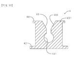
- FIG. 13 is a cross-sectional view of an attachment member in an engine cover according to a third embodiment.
- FIG. 14 is a bottom view of the attachment member.
- FIG. 15 is a partially cut-out perspective cross-sectional view of the attachment member.
- FIG. 1 is a cross-sectional view in a front-rear direction of the engine cover according to the present embodiment, which is attached to an engine member.
- FIG. 2 is a cross-sectional view in the front-rear direction of the engine cover.
- FIG. 3 is a cross-sectional view of an attachment member.
- FIG. 4 is a partially cut-out perspective cross-sectional view of the attachment member.
- the attachment member is shown in an exaggerated manner.
- FIG. 2 shows an upside-down state of the engine cover of FIG. 1 . Therefore, the orientation in the vertical direction is opposite between FIG. 1 and FIG. 2 .
- an engine cover 1 is attached to an upper surface of a cylinder head cover 80 .
- the cylinder head cover 80 is included in the concept of the “engine member” of the present invention.
- Two attachment pins 81 are provided to project from the upper surface of the cylinder head cover 80 in the front-rear direction.
- the two attachment pins 81 are each made of metal, and each have a leg portion 810 fixed to the cylinder head cover 80 and a head portion 811 in a spherical shape with larger diameter than that of the leg portion 810 .
- the engine cover 1 has a cover body 2 , a skin layer 3 , and two attachment members 4 .
- the cover body 2 is made of urethane foam with a density of 100 kg/m 3 and has the shape of a plate.
- the skin layer 3 is formed of a urethane resin coating.
- the skin layer 3 is disposed so as to cover a lower surface (the upper surface in FIG. 1 ) of the cover body 2 .
- the skin layer 3 is exposed in the engine compartment.
- Two attachment members 4 are each embedded in an upper portion of the cover body 2 .
- Each of the two attachment members 4 has the shape similar to a cylinder and is disposed at a position corresponding to the attachment pin 81 of the cylinder head cover 80 .
- Each of the two attachment members 4 is made of thermoplastic urethane elastomer (TPU).
- TPU thermoplastic urethane elastomer
- the attachment member 4 has a recess 40 , a projection 41 , and a fixing flange 42 .
- the recess 40 is formed recessed downward in the center of an upper end surface 430 of the attachment member 4 .
- An opening of the recess 40 is exposed in the upper surface of the cover body 2 .
- the recess 40 has a taper portion 400 and a housing portion 401 .
- the taper portion 400 is disposed so that the diameter is reduced downwards from the upper end surface 430 of the attachment member 4 .
- the housing portion 401 has a generally spherical shape, and is disposed below the taper portion 400 .
- the inner diameter of the housing portion 401 is generally the same as the outer diameter of the head portion 811 of the attachment pin 81 .
- the head portion 811 of the attachment pin 81 is accommodated in the housing portion 401 .
- the projection 41 is provided to project from the upper end surface 430 of the attachment member 4 .
- the upper end surface 430 of the attachment member 4 is included in the concept of the “opening end surface of the recess” of the present invention.
- the projection 41 has the semi-spherical shape in cross section, and is disposed in a ring shape around the opening of the recess 40 .
- the fixing flange 42 has the circular shape.
- the fixing flange 42 is disposed around the lower end part of the attachment member 4 so as to extend in the direction in which the diameter is increased.
- the lower end part of the attachment member 4 is included in the concept of the “end part on the opposite side from the opening end part of the recess” of the present invention.
- the engine cover 1 is disposed above the cylinder head cover 80 so that the attachment pin 81 is horizontally aligned with the recess 40 . Then, the engine cover 1 is pressed against the cylinder head cover 80 . Accordingly, the head portion 811 of the attachment pin 81 is press-fitted into the housing portion 401 through the taper portion 400 of the recess 40 . The engine cover 1 is thus attached to the cylinder head cover 80 .
- the method for manufacturing the engine cover 1 according to the present embodiment includes a placement process, a mold clamping process, a molding process, and a mold opening process.
- FIG. 5 is a cross-sectional view of a molding die in the placement process.
- FIG. 6 is a cross-sectional view of the molding die in the mold clamping process.
- FIG. 7 is a cross-sectional view of the molding die in the molding process.
- FIG. 8 is an enlarged view of an inside of a circle VIII in FIG. 7 .
- FIG. 9 is a cross-sectional view of the molding die in the mold opening process.
- a molding die 5 includes an upper die 50 , an intermediate die 51 , and a lower die 52 .
- a protrusion 500 having the same shape and size as those of the attachment pin 81 is disposed on a lower surface of the upper die 50 .
- a urethane resin coating is applied to a die surface of the lower die 52 by spraying.
- a coating film thus formed is then dried to form the skin layer 3 on the die surface of the lower die 52 .
- the intermediate die 51 is fixed to the upper die 50 .
- the attachment member 4 is attached to the upper die 50 .
- the projection 41 of the attachment member 4 is brought into elastic contact with a lower surface 501 of the upper die 50 .
- a mold clamping is performed by mounting the upper die 50 and the intermediate die 51 on the lower die 52 on which the skin layer 3 is disposed.
- a foamed urethane resin material 20 is poured into a cavity 53 for foam molding, and the cover body 2 is molded.
- the projection 41 of the attachment member 4 is brought into elastic contact with the lower surface 501 of the upper die 50 .
- the projection 41 is pressed against the lower surface 501 of the upper die 50 from below due to foaming pressure of the foamed urethane resin material 20 .
- the projection 41 is pressed into contact with the lower surface 501 so as to become a barrier. This suppresses entry of the foamed urethane resin material 20 into the recess 40 .
- the upper die 50 is removed first. Then, the intermediate die 51 is removed. Finally, the engine cover 1 into which the cover body 2 , the skin layer 3 , and the attachment member 4 are integrated is taken out. The engine cover 1 shown in FIG. 2 is thus manufactured.
- the attachment member 4 is made of thermoplastic urethane elastomer.
- the cover body 2 is made of urethane foam.
- the thermoplastic urethane elastomer has the good adhesion to the urethane foam. Therefore, the attachment member 4 can be adhered to the cover body 2 by integral molding. Further, the adhesive strength between the attachment member 4 and the cover body 2 is high, whereby the attachment member 4 does not easily fall off from the cover body 2 even when the engine cover 1 is detached for maintenance, etc.
- vibrations from an engine transmitted through the cylinder head cover 80 can be absorbed by the attachment member 4 and the cover body 2 . Therefore, the engine cover 1 excels in sound absorption performance.
- the engine cover 1 of the present embodiment it is not necessary to attach the attachment member 4 after the cover body 2 is manufactured.
- An attachment base that secures the attachment member 4 is also not necessary. Therefore, the number of processing steps can be reduced compared to the related art, and the engine cover 1 can be manufactured at a lower cost.
- the engine cover 1 of the present embodiment does not include a full hard covering material but includes the cover body 2 made of urethane foam and the skin layer 3 formed of the urethane resin coating. Therefore, the engine cover 1 is lightweight.
- the cover body 2 is formed of urethane foam with a density of 100 kg/m 3 .
- the cover body 2 is hard compared to the sound absorption layer of the engine cover according to the related art. Thus, appropriate rigidity is applied to the cover body 2 without reducing the sound absorption performance. Accordingly, an excellent sound absorption performance of the engine cover 1 is achieved while the entire shape of the engine cover 1 is kept.
- the skin layer 3 is formed of a urethane material which is the same as that of the cover body 2 .
- the skin layer 3 has the good adhesion to the cover body 2 without affecting the cover body 2 much.
- the coating film that has good flexibility and excels in cold resistance, compared to an acrylic resin coating, can be formed. Therefore, the skin layer 3 excels in flexibility and cold resistance.
- the projection 41 is disposed on the upper end surface 430 of the attachment member 4 .
- the projection 41 is brought into elastic contact with the lower surface 501 of the upper die 50 .
- the contact area between the projection 41 and the lower surface 501 is smaller than that when the entire upper end surface 430 contacts the lower surface 501 . Therefore, when the foaming pressure is applied during foam molding, the projection 41 is pressed into contact with the lower surface 501 with large force. Accordingly, the adhesiveness between the projection 41 and the lower surface 501 is increased, resulting in excellent sealing performance. This suppresses entry of the foamed urethane resin material 20 into the recess 40 during foam molding.
- the engine cover 1 is manufactured using the molding die 5 including the upper die 50 , the intermediate die 51 , and the lower die 52 .
- the attachment member 4 is attached to the lower surface 501 of the upper die 50 .
- the upper die 50 is removed, and then the intermediate die 51 is removed.
- a molded component engine cover 1
- gas can be discharged from between the upper die 50 and the intermediate die 51 . Therefore, a short shot of the foamed urethane resin material 20 can be suppressed.
- the engine cover 1 has the fixing flange 42 on the side of the lower end part of the attachment member 4 . Therefore, the adhesion area between the attachment member 4 and the cover body 2 increases, which improves the adhesive strength.
- FIG. 10 is a cross-sectional view of the attachment member in the engine cover according to the present embodiment.
- FIG. 11 is a partially cut-out perspective cross-sectional view of the attachment member.
- components corresponding to those of FIG. 3 are denoted by the same reference numerals.
- components corresponding to those of FIG. 4 are denoted by the same reference numerals.
- an attachment member 4 has a recess 40 , a sealing flange 44 , and a fixing flange 42 .
- the sealing flange 44 has the circular shape.
- the sealing flange 44 is disposed around an upper end part 431 of the attachment member 4 so as to extend in a direction in which the diameter is increased.
- the upper end part 431 of the attachment member 4 is included in the concept of the “opening end part of the recess” of the present invention.
- FIG. 12 is an enlarged cross-sectional view of the attachment member and its surroundings in the molding process.
- components corresponding to those of FIG. 8 are denoted by the same reference numerals.
- a lower surface 501 of an upper die 50 has a stepped portion 502 in an area in which the attachment member 4 is disposed.
- the side peripheral surface of the sealing flange 44 is brought into elastic contact with the stepped portion 502 .
- the sealing flange 44 is pressed into contact with the lower surface 501 of the upper die 50 including the stepped portion 502 during foam molding.
- the sealing flange 44 becomes a barrier, and this suppresses entry of the foamed urethane resin material 20 into the recess 40 .
- the engine cover according to the present embodiment has the same operation and effects as those of the engine cover according to the first embodiment with respect to portions with common structures.
- the sealing flange 44 is disposed as a sealing portion in the periphery of the upper end part 431 of the attachment member 4 according to the present embodiment.
- the sealing flange 44 becomes a barrier that prevents the expanding foamed urethane resin material 20 from flowing from below. This suppresses entry of the foamed urethane resin material 20 into the recess 40 .
- FIG. 13 is a cross-sectional view of an attachment member in an engine cover according to the present embodiment.
- FIG. 14 is a bottom view of the attachment member.
- FIG. 15 is a partially cut-out perspective cross-sectional view of the attachment member.
- components corresponding to those of FIG. 3 are denoted by the same reference numerals.
- components corresponding to those of FIG. 4 are denoted by the same reference numerals.
- an attachment member 4 has a recess 40 , a projection 41 , a fixing flange 42 , a thinning portion 45 , and reinforcement ribs 46 .
- the thinning portion 45 is disposed so as to surround the recess 40 .
- Four of the reinforcement ribs 46 are disposed in total.
- the reinforcement ribs 46 are disposed so as to divide the thinning portion 45 around the housing portion 401 into four sections when viewed from a lower end surface (bottom surface) 432 of the attachment member 4 .
- the reinforcement ribs 46 are each disposed so as to pass through the thinning portion 45 and connect the periphery of the housing portion 401 and a side wall 47 .
- the engine cover according the present embodiment is manufactured in the same method as that of the engine cover according to the first embodiment.
- the engine cover according to the present embodiment has the same operation and effects as those of the engine cover according to the first embodiment with respect to portions with common structures.
- the attachment member 4 according to the present embodiment has the thinning portion 45 . Therefore, the attachment member 4 can be lightweight accordingly.
- the foamed urethane resin material 20 enters the thinning portion 45 during foam molding. Therefore, the adhesion area between the attachment member 4 and the cover body 2 increases, and the attachment member 4 and the cover body 2 can be adhered to each other more securely.
- the attachment member 4 according to the present embodiment has reinforcement ribs 46 . This maintains the rigidity of the periphery of the recess 40 even though the thinning portion 45 is disposed around the recess 40 .
- the rigidity of the periphery of the recess 40 is high, an operator can confirm that the engine cover is surely set to the cylinder head cover when a head portion 811 of the attachment pin 81 is press-fitted into the housing portion 401 of the recess 40 during the attachment of the engine cover. Therefore, it becomes easier to determine whether or not the engine cover is securely attached to the cylinder head cover.
- Embodiments of the engine cover in the present invention were described above. However, the embodiments of the present invention are not particularly limited to the embodiments described above. The present invention can be embodied in various modifications or improvements that can be achieved by those skilled in the art.
- the material of the attachment member is not particularly limited as far as it is elastic and can be adhered to the cover body by integral molding.
- a projection is disposed on the opening end surface of the recess
- a sealing flange is disposed on the opening end part of the recess.
- the size and shape of the projection and the sealing flange, etc. are not particularly limited.
- the attachment member may have both a projection disposed on the opening end surface of the recess and a sealing flange disposed on the opening end part of the recess.
- the attachment member is provided with the thinning portion and the reinforcement rib.
- a mode for disposing the thinning portion and the reinforcement rib is not particularly limited.
- only the thinning portion may be disposed, and the reinforcement rib may not be disposed.
- the reinforcement rib is disposed, its shape and number may be determined as necessary in consideration of the rigidity and the like of the periphery of the recess.
- the fixing flange is disposed at the end part on the opposite side from the opening end part of the recess.
- the fixing flange is not particularly necessary.
- a projection and the like may also be disposed on the side or the bottom of the attachment member.
- the density of urethane foam that forms the cover body is not particularly limited. As described in the above embodiments, in the case where a skin layer is formed of a coating, the density of urethane foam may be set as 80 kg/m 3 or more to 120 kg/m 3 or less from the viewpoint of achieving an excellent sound absorption performance of the cover body and keeping the entire shape of the cover body.
- the coating that forms the skin layer is not limited to the urethane resin coating.
- various coatings that can be adhered to the cover body such as an acrylic resin coating, can be used.
- the skin layer may not be formed of a coating but be formed by molding the resin separately. In such a case, the skin layer formed by molding the resin is disposed in a molding die to perform foam molding for the foamed urethane resin material. Alternatively, the skin layer formed by molding the resin may be adhered to the cover body into which the attachment member is integrated.
- the engine member, to which the engine cover is to be attached may include an intake manifold, wire harnesses, brackets, and the like, in addition to a cylinder head cover.
Landscapes
- Engineering & Computer Science (AREA)
- General Engineering & Computer Science (AREA)
- Mechanical Engineering (AREA)
- Chemical & Material Sciences (AREA)
- Combustion & Propulsion (AREA)
- Physics & Mathematics (AREA)
- Acoustics & Sound (AREA)
- Cylinder Crankcases Of Internal Combustion Engines (AREA)
- Superstructure Of Vehicle (AREA)
- Connection Of Plates (AREA)
Applications Claiming Priority (3)
| Application Number | Priority Date | Filing Date | Title |
|---|---|---|---|
| JP2012199529A JP6073610B2 (ja) | 2012-09-11 | 2012-09-11 | エンジンカバー |
| JP2012-199529 | 2012-09-11 | ||
| PCT/JP2013/074407 WO2014042157A1 (ja) | 2012-09-11 | 2013-09-10 | エンジンカバー |
Related Parent Applications (1)
| Application Number | Title | Priority Date | Filing Date |
|---|---|---|---|
| PCT/JP2013/074407 Continuation WO2014042157A1 (ja) | 2012-09-11 | 2013-09-10 | エンジンカバー |
Publications (2)
| Publication Number | Publication Date |
|---|---|
| US20150075482A1 US20150075482A1 (en) | 2015-03-19 |
| US9816460B2 true US9816460B2 (en) | 2017-11-14 |
Family
ID=50278268
Family Applications (1)
| Application Number | Title | Priority Date | Filing Date |
|---|---|---|---|
| US14/550,179 Active 2033-10-26 US9816460B2 (en) | 2012-09-11 | 2014-11-21 | Engine cover |
Country Status (5)
| Country | Link |
|---|---|
| US (1) | US9816460B2 (ja) |
| EP (1) | EP2896805B1 (ja) |
| JP (1) | JP6073610B2 (ja) |
| CN (1) | CN104169541B (ja) |
| WO (1) | WO2014042157A1 (ja) |
Cited By (5)
| Publication number | Priority date | Publication date | Assignee | Title |
|---|---|---|---|---|
| US10982698B2 (en) * | 2018-02-08 | 2021-04-20 | Fastmount Limited | Surface panel connection system |
| US20210190114A1 (en) * | 2018-09-20 | 2021-06-24 | Sumitomo Riko Company Limited | Grommet for attaching cover and cover |
| US11353112B2 (en) | 2018-09-28 | 2022-06-07 | Federal-Mogul Motorparts Llc | Gasket and grommet installation assembly |
| EP4253772A1 (en) * | 2022-04-01 | 2023-10-04 | BDR Thermea Group B.V. | Fixing assembly |
| US11959415B2 (en) | 2022-01-07 | 2024-04-16 | Honda Motor Co., Ltd. | Internal combustion engine fitted with engine cover |
Families Citing this family (17)
| Publication number | Priority date | Publication date | Assignee | Title |
|---|---|---|---|---|
| JP2015217687A (ja) * | 2014-05-14 | 2015-12-07 | 小島プレス工業株式会社 | 車両用エンジンカバー及びその製造方法 |
| JP6232451B2 (ja) * | 2014-07-09 | 2017-11-15 | 住友理工株式会社 | エンジンカバー |
| TW201706156A (zh) * | 2015-04-15 | 2017-02-16 | 歐拓管理股份公司 | 頂蓋、扣合固定件、固定系統、模造裝置及製造扣合固定件之方法 |
| DE102016103931A1 (de) * | 2016-03-04 | 2017-09-07 | Lisa Dräxlmaier GmbH | Schraube für Bauteile aus geschäumten Kunststoff |
| GB2562230B (en) * | 2017-05-08 | 2019-12-11 | Jaguar Land Rover Ltd | Thermal encapsulation apparatus |
| US10336248B2 (en) * | 2017-06-06 | 2019-07-02 | Ford Global Technologies, Llc | Engine cover having embedded circuit for illuminated badging |
| US10495024B2 (en) | 2017-10-05 | 2019-12-03 | Ford Global Technologies, Llc | Reinforced vehicle component cover |
| US10315589B2 (en) | 2017-10-05 | 2019-06-11 | Ford Global Technologies, Llc | Reinforced vehicle component cover |
| US10415619B1 (en) | 2018-03-05 | 2019-09-17 | Ford Global Technologies, Llc | Toolless fastener for engine cover |
| DE102018109066A1 (de) * | 2018-04-17 | 2019-10-17 | Auria Solutions Uk I Ltd. | Abdeckung, insbesondere für den Motor eines Kraftfahrzeugs |
| DE202018104667U1 (de) | 2018-08-14 | 2018-08-28 | Woco Industrietechnik Gmbh | Federklemmaufnahme und Federklemmverbindung für Schaumbauteile und Schaumbauteil mit Federklemmaufnahme |
| FR3098469B1 (fr) * | 2019-07-11 | 2021-07-16 | Treves Products Services & Innovation | Montage d’un écran de protection acoustique sur un moteur de véhicule automobile |
| DE102019123966A1 (de) * | 2019-09-06 | 2021-03-11 | Volkswagen Aktiengesellschaft | Akustikdämmelement, System aus Akustikdämmelementen, Antriebsvorrichtung mit Dämmelementen und Verfahren für die Montage von einem Akustikdämmelement an einer Antriebsvorrichtung |
| JP2022072836A (ja) * | 2020-10-30 | 2022-05-17 | 株式会社イノアックコーポレーション | 吸音カバーと音源部品 |
| KR102591333B1 (ko) * | 2020-12-11 | 2023-10-20 | 엔브이에이치코리아(주) | 고압연료펌프용 흡차음커버 |
| WO2023174741A1 (en) * | 2022-03-14 | 2023-09-21 | Bdr Thermea Group B.V. | Fixing assembly |
| JP2024064655A (ja) * | 2022-10-28 | 2024-05-14 | トヨタ自動車株式会社 | エンジン |
Citations (13)
| Publication number | Priority date | Publication date | Assignee | Title |
|---|---|---|---|---|
| JP2004190810A (ja) | 2002-12-12 | 2004-07-08 | Bridgestone Corp | Ea材の取付構造及び係止ピース |
| WO2004090307A1 (de) | 2003-04-14 | 2004-10-21 | Carcoustics Tech Center Gmbh | Abdeckung für ein aggregat im motorraum eines kraftfahrzeuges |
| JP2005178134A (ja) | 2003-12-18 | 2005-07-07 | Bridgestone Corp | Ea材及びその製造方法 |
| US20050280195A1 (en) * | 2004-06-18 | 2005-12-22 | Basf Corporation | Mount assembly |
| US20060125286A1 (en) * | 2002-10-10 | 2006-06-15 | Toshiyuki Horimatsu | Ea member attaching construction |
| JP2006336743A (ja) | 2005-06-01 | 2006-12-14 | Toyota Motor Corp | グロメットを用いた構造物の固定構造 |
| WO2008055806A1 (de) | 2006-11-08 | 2008-05-15 | Polytec Automotive Gmbh & Co. Kg | Motorabdeckung mit schaum als fussgängerschutz |
| JP2008196587A (ja) | 2007-02-13 | 2008-08-28 | Ntn Corp | 摺動部材および摺動装置 |
| JP2008298084A (ja) | 2007-05-02 | 2008-12-11 | Oiles Ind Co Ltd | 合成樹脂製の滑り軸受 |
| JP2011021486A (ja) | 2009-07-13 | 2011-02-03 | Toyoda Gosei Co Ltd | エンジンカバーの取付構造 |
| JP2012037002A (ja) | 2010-08-09 | 2012-02-23 | Bridgestone Corp | 発泡成形部材、その取付用クリップ、発泡成形部材の製造方法並びに発泡成形部材の取付構造 |
| JP2012037001A (ja) | 2010-08-09 | 2012-02-23 | Bridgestone Corp | 発泡成形部材、その取付用クリップ、発泡成形部材の製造方法並びに発泡成形部材の取付構造 |
| CN102396023A (zh) | 2009-10-27 | 2012-03-28 | 东海橡胶工业株式会社 | 隔音罩及其制造方法 |
Family Cites Families (4)
| Publication number | Priority date | Publication date | Assignee | Title |
|---|---|---|---|---|
| US6206604B1 (en) * | 1997-09-12 | 2001-03-27 | Bollhoff Gmbh | Plug-in coupling |
| US6838155B2 (en) * | 2002-02-28 | 2005-01-04 | Woodbridge Foam Corporation | Foam pad and process for production thereof |
| JP4370766B2 (ja) * | 2002-10-10 | 2009-11-25 | 株式会社ブリヂストン | Ea材の取付構造 |
| JP4400455B2 (ja) * | 2004-12-27 | 2010-01-20 | 豊田合成株式会社 | エンジンカバーの取付構造 |
-
2012
- 2012-09-11 JP JP2012199529A patent/JP6073610B2/ja active Active
-
2013
- 2013-09-10 CN CN201380014739.1A patent/CN104169541B/zh active Active
- 2013-09-10 EP EP13836351.0A patent/EP2896805B1/en active Active
- 2013-09-10 WO PCT/JP2013/074407 patent/WO2014042157A1/ja unknown
-
2014
- 2014-11-21 US US14/550,179 patent/US9816460B2/en active Active
Patent Citations (16)
| Publication number | Priority date | Publication date | Assignee | Title |
|---|---|---|---|---|
| US20060125286A1 (en) * | 2002-10-10 | 2006-06-15 | Toshiyuki Horimatsu | Ea member attaching construction |
| JP2004190810A (ja) | 2002-12-12 | 2004-07-08 | Bridgestone Corp | Ea材の取付構造及び係止ピース |
| WO2004090307A1 (de) | 2003-04-14 | 2004-10-21 | Carcoustics Tech Center Gmbh | Abdeckung für ein aggregat im motorraum eines kraftfahrzeuges |
| US20060073310A1 (en) * | 2003-04-14 | 2006-04-06 | Detlef Winkler | Cover for a unit in the engine compartment of a motor vehicle |
| JP2006522890A (ja) | 2003-04-14 | 2006-10-05 | カーコースティクス テック センター ゲゼルシャフト ミット ベシュレンクテル ハフツング | 自動車のエンジンルーム内の装置のためのカバー |
| JP2005178134A (ja) | 2003-12-18 | 2005-07-07 | Bridgestone Corp | Ea材及びその製造方法 |
| US20050280195A1 (en) * | 2004-06-18 | 2005-12-22 | Basf Corporation | Mount assembly |
| JP2006336743A (ja) | 2005-06-01 | 2006-12-14 | Toyota Motor Corp | グロメットを用いた構造物の固定構造 |
| WO2008055806A1 (de) | 2006-11-08 | 2008-05-15 | Polytec Automotive Gmbh & Co. Kg | Motorabdeckung mit schaum als fussgängerschutz |
| JP2008196587A (ja) | 2007-02-13 | 2008-08-28 | Ntn Corp | 摺動部材および摺動装置 |
| JP2008298084A (ja) | 2007-05-02 | 2008-12-11 | Oiles Ind Co Ltd | 合成樹脂製の滑り軸受 |
| JP2011021486A (ja) | 2009-07-13 | 2011-02-03 | Toyoda Gosei Co Ltd | エンジンカバーの取付構造 |
| CN102396023A (zh) | 2009-10-27 | 2012-03-28 | 东海橡胶工业株式会社 | 隔音罩及其制造方法 |
| US20120168246A1 (en) | 2009-10-27 | 2012-07-05 | Tokai Chemical Industries, Ltd. | Soundproofing cover and method of manufacturing same |
| JP2012037002A (ja) | 2010-08-09 | 2012-02-23 | Bridgestone Corp | 発泡成形部材、その取付用クリップ、発泡成形部材の製造方法並びに発泡成形部材の取付構造 |
| JP2012037001A (ja) | 2010-08-09 | 2012-02-23 | Bridgestone Corp | 発泡成形部材、その取付用クリップ、発泡成形部材の製造方法並びに発泡成形部材の取付構造 |
Non-Patent Citations (10)
| Title |
|---|
| English translation of JP2006-522890, dated Oct. 5, 2006. |
| International Preliminary Report on Patentability for PCT/JP2013/074407, dated Mar. 17, 2015. |
| Office Action issued in China Counterpart Patent Appl. No. 201380014739.1, dated Dec. 30, 2015 , along with an English translation thereof. |
| Office Action issued in China Counterpart Patent Appl. No. 201380014739.1, dated Sep. 18, 2016 , along with an English translation thereof. |
| Office Action issued in Japan Counterpart Patent Appl. No. 2012-199529, dated May 31, 2016 , along with an English translation thereof. |
| Partial English language translation of JP 2004-190810 having a date of Jul. 8, 2004. |
| Partial English language translation of JP 2008-196587 having a date of Aug. 28, 2008. |
| Partial English language translation of JP 2008-298084 having a date of Dec. 11, 2008. |
| Search report from PCT/JP2013/074407, dated Dec. 17, 2013. |
| Search Report issued in European Patent Office (EPO) Patent Application No. 13836351.0, dated Apr. 22, 2016. |
Cited By (7)
| Publication number | Priority date | Publication date | Assignee | Title |
|---|---|---|---|---|
| US10982698B2 (en) * | 2018-02-08 | 2021-04-20 | Fastmount Limited | Surface panel connection system |
| US11946505B2 (en) | 2018-02-08 | 2024-04-02 | Fastmount Limited | Surface panel connection system |
| US20210190114A1 (en) * | 2018-09-20 | 2021-06-24 | Sumitomo Riko Company Limited | Grommet for attaching cover and cover |
| US11846309B2 (en) * | 2018-09-20 | 2023-12-19 | Sumitomo Riko Company Limited | Grommet for attaching cover and cover |
| US11353112B2 (en) | 2018-09-28 | 2022-06-07 | Federal-Mogul Motorparts Llc | Gasket and grommet installation assembly |
| US11959415B2 (en) | 2022-01-07 | 2024-04-16 | Honda Motor Co., Ltd. | Internal combustion engine fitted with engine cover |
| EP4253772A1 (en) * | 2022-04-01 | 2023-10-04 | BDR Thermea Group B.V. | Fixing assembly |
Also Published As
| Publication number | Publication date |
|---|---|
| EP2896805A4 (en) | 2016-05-25 |
| EP2896805A1 (en) | 2015-07-22 |
| US20150075482A1 (en) | 2015-03-19 |
| WO2014042157A1 (ja) | 2014-03-20 |
| JP2014055529A (ja) | 2014-03-27 |
| EP2896805B1 (en) | 2019-12-04 |
| CN104169541B (zh) | 2017-10-03 |
| CN104169541A (zh) | 2014-11-26 |
| JP6073610B2 (ja) | 2017-02-01 |
Similar Documents
| Publication | Publication Date | Title |
|---|---|---|
| US9816460B2 (en) | Engine cover | |
| JP5772444B2 (ja) | クランプ | |
| US10374302B2 (en) | Antenna unit | |
| US9610718B2 (en) | Automotive side view mirror attachment assembly and method of making same | |
| JP6232451B2 (ja) | エンジンカバー | |
| US8876195B2 (en) | Shock absorber and vehicular door trim including the same | |
| JP6517173B2 (ja) | 車両用アンテナ装置 | |
| CA2911539C (en) | Fuel cell case | |
| US8833836B2 (en) | Tunable water deflector | |
| CN214153905U (zh) | 线束安装结构及车辆 | |
| US10962083B2 (en) | Vibration-damping device | |
| US8950737B2 (en) | Antivibration device | |
| JP7480148B2 (ja) | 車体の前壁用の遮音要素およびそのような遮音要素のための支持要素 | |
| US20190322228A1 (en) | Vehicle acoustic dash panel seal and guide | |
| KR102343924B1 (ko) | 프레임 인서트형 발포커버 | |
| JP2012111310A (ja) | 送受波器保護装置 | |
| JP2006264554A (ja) | 自動車用アームレスト | |
| US9873389B2 (en) | Vehicle cushion component | |
| JP4602774B2 (ja) | 成形部品 | |
| US20180334068A1 (en) | Car safety seat | |
| JP5342483B2 (ja) | 防振装置 | |
| JP5338444B2 (ja) | 車両用内装部品 | |
| JP2006168464A (ja) | フェンダーサイドプロテクタ | |
| JPS601025A (ja) | フユエルフイラ−チユ−ブの取付構造 | |
| JP2011148434A (ja) | 車両用内装部品 |
Legal Events
| Date | Code | Title | Description |
|---|---|---|---|
| AS | Assignment |
Owner name: SUMITOMO RIKO COMPANY LIMITED, JAPAN Free format text: ASSIGNMENT OF ASSIGNORS INTEREST;ASSIGNORS:KONDO, HIROYUKI;ISHII, KIMIO;REEL/FRAME:036971/0264 Effective date: 20151019 Owner name: TOKAI CHEMICAL INDUSTRIES, LTD., JAPAN Free format text: ASSIGNMENT OF ASSIGNORS INTEREST;ASSIGNORS:KONDO, HIROYUKI;ISHII, KIMIO;REEL/FRAME:036971/0264 Effective date: 20151019 |
|
| STCF | Information on status: patent grant |
Free format text: PATENTED CASE |
|
| MAFP | Maintenance fee payment |
Free format text: PAYMENT OF MAINTENANCE FEE, 4TH YEAR, LARGE ENTITY (ORIGINAL EVENT CODE: M1551); ENTITY STATUS OF PATENT OWNER: LARGE ENTITY Year of fee payment: 4 |