US9776346B2 - Particle foam component and method for production thereof - Google Patents
Particle foam component and method for production thereof Download PDFInfo
- Publication number
- US9776346B2 US9776346B2 US14/775,106 US201414775106A US9776346B2 US 9776346 B2 US9776346 B2 US 9776346B2 US 201414775106 A US201414775106 A US 201414775106A US 9776346 B2 US9776346 B2 US 9776346B2
- Authority
- US
- United States
- Prior art keywords
- foam body
- cover layer
- surface structure
- mold
- areas
- Prior art date
- Legal status (The legal status is an assumption and is not a legal conclusion. Google has not performed a legal analysis and makes no representation as to the accuracy of the status listed.)
- Expired - Fee Related
Links
Images


Classifications
-
- B—PERFORMING OPERATIONS; TRANSPORTING
- B29—WORKING OF PLASTICS; WORKING OF SUBSTANCES IN A PLASTIC STATE IN GENERAL
- B29C—SHAPING OR JOINING OF PLASTICS; SHAPING OF MATERIAL IN A PLASTIC STATE, NOT OTHERWISE PROVIDED FOR; AFTER-TREATMENT OF THE SHAPED PRODUCTS, e.g. REPAIRING
- B29C44/00—Shaping by internal pressure generated in the material, e.g. swelling or foaming ; Producing porous or cellular expanded plastics articles
- B29C44/34—Auxiliary operations
- B29C44/56—After-treatment of articles, e.g. for altering the shape
-
- B—PERFORMING OPERATIONS; TRANSPORTING
- B29—WORKING OF PLASTICS; WORKING OF SUBSTANCES IN A PLASTIC STATE IN GENERAL
- B29C—SHAPING OR JOINING OF PLASTICS; SHAPING OF MATERIAL IN A PLASTIC STATE, NOT OTHERWISE PROVIDED FOR; AFTER-TREATMENT OF THE SHAPED PRODUCTS, e.g. REPAIRING
- B29C44/00—Shaping by internal pressure generated in the material, e.g. swelling or foaming ; Producing porous or cellular expanded plastics articles
- B29C44/34—Auxiliary operations
- B29C44/58—Moulds
- B29C44/585—Moulds with adjustable size of the mould cavity
-
- B—PERFORMING OPERATIONS; TRANSPORTING
- B29—WORKING OF PLASTICS; WORKING OF SUBSTANCES IN A PLASTIC STATE IN GENERAL
- B29C—SHAPING OR JOINING OF PLASTICS; SHAPING OF MATERIAL IN A PLASTIC STATE, NOT OTHERWISE PROVIDED FOR; AFTER-TREATMENT OF THE SHAPED PRODUCTS, e.g. REPAIRING
- B29C45/00—Injection moulding, i.e. forcing the required volume of moulding material through a nozzle into a closed mould; Apparatus therefor
- B29C45/14—Injection moulding, i.e. forcing the required volume of moulding material through a nozzle into a closed mould; Apparatus therefor incorporating preformed parts or layers, e.g. injection moulding around inserts or for coating articles
- B29C45/1418—Injection moulding, i.e. forcing the required volume of moulding material through a nozzle into a closed mould; Apparatus therefor incorporating preformed parts or layers, e.g. injection moulding around inserts or for coating articles the inserts being deformed or preformed, e.g. by the injection pressure
-
- B—PERFORMING OPERATIONS; TRANSPORTING
- B29—WORKING OF PLASTICS; WORKING OF SUBSTANCES IN A PLASTIC STATE IN GENERAL
- B29C—SHAPING OR JOINING OF PLASTICS; SHAPING OF MATERIAL IN A PLASTIC STATE, NOT OTHERWISE PROVIDED FOR; AFTER-TREATMENT OF THE SHAPED PRODUCTS, e.g. REPAIRING
- B29C45/00—Injection moulding, i.e. forcing the required volume of moulding material through a nozzle into a closed mould; Apparatus therefor
- B29C45/14—Injection moulding, i.e. forcing the required volume of moulding material through a nozzle into a closed mould; Apparatus therefor incorporating preformed parts or layers, e.g. injection moulding around inserts or for coating articles
- B29C45/14778—Injection moulding, i.e. forcing the required volume of moulding material through a nozzle into a closed mould; Apparatus therefor incorporating preformed parts or layers, e.g. injection moulding around inserts or for coating articles the article consisting of a material with particular properties, e.g. porous, brittle
- B29C45/14795—Porous or permeable material, e.g. foam
-
- B—PERFORMING OPERATIONS; TRANSPORTING
- B32—LAYERED PRODUCTS
- B32B—LAYERED PRODUCTS, i.e. PRODUCTS BUILT-UP OF STRATA OF FLAT OR NON-FLAT, e.g. CELLULAR OR HONEYCOMB, FORM
- B32B27/00—Layered products comprising a layer of synthetic resin
- B32B27/06—Layered products comprising a layer of synthetic resin as the main or only constituent of a layer, which is next to another layer of the same or of a different material
- B32B27/065—Layered products comprising a layer of synthetic resin as the main or only constituent of a layer, which is next to another layer of the same or of a different material of foam
-
- B—PERFORMING OPERATIONS; TRANSPORTING
- B32—LAYERED PRODUCTS
- B32B—LAYERED PRODUCTS, i.e. PRODUCTS BUILT-UP OF STRATA OF FLAT OR NON-FLAT, e.g. CELLULAR OR HONEYCOMB, FORM
- B32B5/00—Layered products characterised by the non- homogeneity or physical structure, i.e. comprising a fibrous, filamentary, particulate or foam layer; Layered products characterised by having a layer differing constitutionally or physically in different parts
- B32B5/18—Layered products characterised by the non- homogeneity or physical structure, i.e. comprising a fibrous, filamentary, particulate or foam layer; Layered products characterised by having a layer differing constitutionally or physically in different parts characterised by features of a layer of foamed material
-
- B—PERFORMING OPERATIONS; TRANSPORTING
- B29—WORKING OF PLASTICS; WORKING OF SUBSTANCES IN A PLASTIC STATE IN GENERAL
- B29K—INDEXING SCHEME ASSOCIATED WITH SUBCLASSES B29B, B29C OR B29D, RELATING TO MOULDING MATERIALS OR TO MATERIALS FOR MOULDS, REINFORCEMENTS, FILLERS OR PREFORMED PARTS, e.g. INSERTS
- B29K2023/00—Use of polyalkenes or derivatives thereof as moulding material
- B29K2023/10—Polymers of propylene
- B29K2023/12—PP, i.e. polypropylene
-
- B—PERFORMING OPERATIONS; TRANSPORTING
- B29—WORKING OF PLASTICS; WORKING OF SUBSTANCES IN A PLASTIC STATE IN GENERAL
- B29K—INDEXING SCHEME ASSOCIATED WITH SUBCLASSES B29B, B29C OR B29D, RELATING TO MOULDING MATERIALS OR TO MATERIALS FOR MOULDS, REINFORCEMENTS, FILLERS OR PREFORMED PARTS, e.g. INSERTS
- B29K2025/00—Use of polymers of vinyl-aromatic compounds or derivatives thereof as moulding material
- B29K2025/04—Polymers of styrene
- B29K2025/06—PS, i.e. polystyrene
-
- B—PERFORMING OPERATIONS; TRANSPORTING
- B29—WORKING OF PLASTICS; WORKING OF SUBSTANCES IN A PLASTIC STATE IN GENERAL
- B29K—INDEXING SCHEME ASSOCIATED WITH SUBCLASSES B29B, B29C OR B29D, RELATING TO MOULDING MATERIALS OR TO MATERIALS FOR MOULDS, REINFORCEMENTS, FILLERS OR PREFORMED PARTS, e.g. INSERTS
- B29K2105/00—Condition, form or state of moulded material or of the material to be shaped
- B29K2105/04—Condition, form or state of moulded material or of the material to be shaped cellular or porous
-
- B—PERFORMING OPERATIONS; TRANSPORTING
- B29—WORKING OF PLASTICS; WORKING OF SUBSTANCES IN A PLASTIC STATE IN GENERAL
- B29L—INDEXING SCHEME ASSOCIATED WITH SUBCLASS B29C, RELATING TO PARTICULAR ARTICLES
- B29L2009/00—Layered products
-
- B—PERFORMING OPERATIONS; TRANSPORTING
- B32—LAYERED PRODUCTS
- B32B—LAYERED PRODUCTS, i.e. PRODUCTS BUILT-UP OF STRATA OF FLAT OR NON-FLAT, e.g. CELLULAR OR HONEYCOMB, FORM
- B32B2266/00—Composition of foam
- B32B2266/08—Closed cell foam
Definitions
- the present invention relates to a particle foam component having a foam body, which is provided with a cover layer made of a plastic material at least in partial areas of its outer surface.
- the present invention pertains to a method for producing a particle foam component, which has a foam body, which is provided with a cover layer made of a plastic material at least in partial areas of its outer surface, wherein the foam body is foamed in a mold and the cover layer is foamed or molded integrally in a subsequent method step.
- particle foam components made of foamed plastic for example, expanded polystyrene (EPS) or expanded polypropylene (EPP) are known and used in many areas in industry, because they have considerable advantages in terms of weight and insulation, especially in terms of heat insulation. They are frequently used, for example, in the automobile industry to reduce weight compared to metallic components or as insulating components against sound, heat or mechanical stress.
- EPS expanded polystyrene
- EPP expanded polypropylene
- a particle foam component subsequently at least in some areas with a plastic material, especially a thermoplastic elastomer, has been known for some time.
- the particle foam component is inserted into the injection mold, wherein a cavity remains between the particle foam component and the injection mold, and a low-viscosity plastic is injected into the cavity at a high temperature and under high pressure.
- the plasticized plastic fills out the cavity between the particle foam component and the wall of the injection mold in the form of a melt. Because of the irregular porous surface structure of the particle foam component, the liquid plastic enters undefined into the near-surface areas of the structure of the particle foam component. In this case, undefined accumulations of material form in the near-surface zones of the structure of the particle foam component and thus non-uniform cross sections of the applied thermoplastic cover layer. This is still acceptable in small particle foam components or in particle foam components, which are invisibly inserted for a user; however, the irregularity over time is conspicuous in large, visible particle foam components and very disturbing in terms of aesthetics.
- a basic object of the present invention is to create a particle foam component which is provided with a cover layer of uniform thickness, wherein the cover layer shall be bonded in a reliable and simple manner to the foam body. Further, a method shall be created, with which a corresponding particle foam component can be produced in a simple manner.
- the above-mentioned object is accomplished by a particle foam component of the present invention. Provisions are made here for the foam body to have a compressed surface structure in its areas supporting the cover layer, wherein the cover layer is bonded in substance to the compressed surface structure of the foam body.
- the present invention is based on the basic idea of not applying the cover layer made of preferably thermoplastic plastic directly on the foamed foam body, but rather those surface areas of the foam body, which shall be provided with the cover layer, are compressed before the application of the cover layer. Provisions may be made here, for example, for the foam pores for forming the compressed surface structure to be melted together and to form a closed surface. In this way, the liquid thermoplastic plastic is prevented from penetrating into the foam body during the application, i.e., during the spraying on. Thus, it is ensured by the compressed surface structure of the foam body that the cover layer has a uniform predetermined thickness.
- the bonding in substance of the cover layer to the compressed surface structure of the foam body ensures a secure, all-over hold of the cover layer on the foam body, without it requiring the use of adhesives, etc. for this.
- cover layer may, however, also be bonded in a positive-locking manner and/or nonpositive-locking manner to the compressed surface structure of the foam body.
- the plastic material of the cover layer is preferably a thermoplastic elastomer.
- the above-mentioned object is accomplished by a compressed surface structure being formed in the surface areas of the foam body supporting the cover layer before applying the cover layer, wherein the cover layer is bonded in substance to the compressed surface structure.
- the original open-pore structure of the foam body is reformed into a homogeneous closed structure by means of compression. Because of the compressed, closed-pore surface structure, the melt flow of the sprayed-on thermoplastic plastic may be uniform and reproducible. This leads to a particle foam component with a defined thickness of the sprayed-on cover layer.
- the bonding in substance of the cover layer to the compressed surface structure of the foam body ensures a secure, all-over hold of the cover layer on the foam body, without requiring the use of adhesives, etc. for this.
- provisions may be made for the compressed surface structure of the foam body to be formed directly during the foaming of the foam body in the mold. This is, for example, possible, by the wall of the mold being adjusted to a predetermined temperature in some sections, so that the particle foam forming in the mold during the foaming melts on this wall of the mold, so that the foam particles in this area of the surface melt together and form a closed, compressed surface structure.
- the compressed surface structure of the foam body is formed only after the foaming of the foam body. This may take place in the same mold, in which the foam body is also foamed; however, it is also possible to transfer the foam body into a different work station.
- the forming of the compressed surface structure of the foam body may be achieved, for example, by the action of an external force of pressure on the foam body. Provisions are preferably made here for those surface areas of the foam body, on which the force of pressure acts, to be melted on at least in some areas before and/or during the application of the force of pressure. A compression of the material and at the same time a smooth outer surface is achieved by means of the melting on and application of the force of pressure.
- the force of pressure may be applied, for example, by means of a punch.
- the punch may also be used at the same time for heating and melting the surface areas of the foam body by the punch being heated.
- a heating device may be arranged in the punch.
- the cover layer which is preferably made of a thermoplastic elastomer, is sprayed onto the foam body in an injection mold.
- the cover layer here is bonded in substance to the compressed surface structure of the foam body.
- provisions may be made in a variant of the present invention for the compressed surface structure of the foam body to be melted on or at least partially melted at least in some areas before and/or during the application of the cover layer.
- FIG. 1 is a sectional view of a mold for foaming a foam body
- FIG. 2 is a sectional view of the mold according to FIG. 1 with a foamed foam body
- FIG. 3 is a sectional view of the mold according to FIG. 2 after formation of the compressed surface structure
- FIG. 4 is a sectional view of the mold according to FIG. 3 after opening the mold;
- FIG. 5 is a sectional view of the mold according to FIG. 4 upon removal of the foam body
- FIG. 6 is a sectional view of the foam body with compressed surface structure
- FIG. 7 is a sectional view of an injection mold with inserted foam body
- FIG. 8 is a sectional view of an injection mold according to FIG. 7 upon closing
- FIG. 9 is a sectional view of the closed injection mold with inserted foam body
- FIG. 10 is a sectional view of the injection mold according to FIG. 9 with molded integrally cover layer;
- FIG. 11 is a sectional view of the opened injection mold upon removal of the particle foam component
- FIG. 12 is a sectional view of the finished particle foam component.
- FIG. 12 shows a schematic view of a particle foam component 10 , which consists of a foam body 11 made of EPP or EPS and is provided on one side with a cover layer 13 made of a thermoplastic elastomer, wherein the foam body 11 has a compressed surface structure 12 in its areas supporting the cover layer 13 .
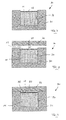
- FIG. 1 shows a schematic view of a mold 20 with a container-like lower mold part 21 , in which an only schematically suggested filling nozzle 22 for inserting foamable plastic particles and two steam nozzles 23 for introducing hot steam into a mold cavity 25 defined by the lower mold part 21 are provided.
- the mold cavity 25 is closed by a cover-like second mold part 24 , which can be inserted into the mold cavity 25 with a punch-like attachment 24 a .
- the cover-like second mold part 24 can be adjusted in relation to the first mold part 21 , as it is suggested by the double arrow A. Further, the second mold part 24 may be heated up to a desired temperature by means of a heating device 26 , which is shown as an example.
- the second mold part 24 In its starting position, the second mold part 24 is retracted from the mold cavity 25 with its punch-like attachment 24 a , as it is shown in FIG. 1 .
- the punch-like second mold part 24 is preheated to a predetermined temperature by activating the heating device 26 and particles made of foamable plastic, especially of EPP or EPS are inserted into the mold cavity 25 by the filling nozzle 22 .
- Hot steam is introduced into the mold cavity 25 by the steam nozzles 23 (arrows D in FIG. 2 ), as a result of which the particles foam and form a mold cavity 25 forming the entire foam body 11 .
- the adjustable second mold part 24 is moved, such that it enters the mold cavity 25 with its punch-like attachment 24 a and compresses the foam body 11 and melts on the surface facing the punch-like attachment 24 a because of its high wall temperature. Due to the melting-on boundary layer of the foam body 11 and the compression resulting from the punch-like attachment 24 a of the second mold part 24 , a compressed, closed-pore surface structure 12 forms in the surface areas of the foam body 11 coming into contact with the second mold part 24 , as it is suggested in FIG. 3 .
- the cover-like second mold part 24 is removed and thus the mold 20 is opened (see FIG. 4 ) and the foam body 11 with compressed surface structure 12 on the top side can be removed from the mold 20 (see FIG. 5 ).
- the cover layer 13 made of a thermoplastic plastic is subsequently sprayed onto the foam body 11 with compressed surface structure 12 shown in FIG. 6 in a further method step, which is explained below on the basis of FIGS. 7 through 11 .
- FIG. 7 shows a schematically shown injection mold 30 with a container-like lower first mold part 31 , which defines a cavity 34 .
- the foam body 11 with compressed surface structure 12 can be inserted into the cavity 34 , as it is shown in FIG. 7 .
- the injection mold 30 is subsequently closed by a cover-like, upper second mold part 32 , in which a spray nozzle 33 is formed, as it is suggested by arrow V in FIG. 8 .
- FIG. 9 shows the closed injection mold 30 with inserted foam body 11 , wherein the cavity 34 is somewhat larger than the foam body 11 , so that a cavity 35 is formed between the top side of the foam body 11 , i.e., between the compressed surface structure 12 of the foam body 11 and the second mold part 32 .
- thermoplastic elastomer can be injected into this cavity 35 by the spray nozzle 33 , which forms the cover layer 13 and forms a positive-locking bonding to the compressed surface structure 12 of the foam body 11 .
- the injection mold 30 is opened and the particle foam component 10 with the foam body 11 and the thermoplastic cover layer 13 , which is bonded to the foam body 11 via the compressed surface structure 12 , can be removed from the injection mold (see FIG. 11 ).
Landscapes
- Engineering & Computer Science (AREA)
- Manufacturing & Machinery (AREA)
- Mechanical Engineering (AREA)
- Laminated Bodies (AREA)
- Injection Moulding Of Plastics Or The Like (AREA)
- Moulds For Moulding Plastics Or The Like (AREA)
Applications Claiming Priority (4)
| Application Number | Priority Date | Filing Date | Title |
|---|---|---|---|
| DE102013004196.1 | 2013-03-12 | ||
| DE102013004196 | 2013-03-12 | ||
| DE102013004196.1A DE102013004196A1 (de) | 2013-03-12 | 2013-03-12 | Partikelschaum-Bauteil und Verfahren zu seiner Herstellung |
| PCT/EP2014/000636 WO2014139667A1 (de) | 2013-03-12 | 2014-03-11 | Partikelschaum-bauteil und verfahren zu seiner herstellung |
Publications (2)
| Publication Number | Publication Date |
|---|---|
| US20160039127A1 US20160039127A1 (en) | 2016-02-11 |
| US9776346B2 true US9776346B2 (en) | 2017-10-03 |
Family
ID=50549277
Family Applications (1)
| Application Number | Title | Priority Date | Filing Date |
|---|---|---|---|
| US14/775,106 Expired - Fee Related US9776346B2 (en) | 2013-03-12 | 2014-03-11 | Particle foam component and method for production thereof |
Country Status (7)
| Country | Link |
|---|---|
| US (1) | US9776346B2 (ja) |
| EP (1) | EP2969459B1 (ja) |
| JP (1) | JP6486841B2 (ja) |
| DE (1) | DE102013004196A1 (ja) |
| ES (1) | ES2665026T3 (ja) |
| PT (1) | PT2969459T (ja) |
| WO (1) | WO2014139667A1 (ja) |
Families Citing this family (4)
| Publication number | Priority date | Publication date | Assignee | Title |
|---|---|---|---|---|
| DE102014008621A1 (de) * | 2014-06-17 | 2015-12-17 | Krallmann Kunststoffverarbeitung Gmbh | Verfahren zur Herstellung eines Partikelschaum-Bauteils |
| DE102016007913B4 (de) | 2016-06-30 | 2018-08-23 | Krallmann Kunststoffverarbeitung Gmbh | Kfz-Verbundbauteil und Verfahren zu seiner Herstellung |
| US10480656B2 (en) * | 2016-08-22 | 2019-11-19 | Tesa Se | Bridge tape with directed foam expansion and method for sealing holes in sheet metal or plastic parts of automobile bodies |
| JP6985187B2 (ja) | 2018-03-15 | 2021-12-22 | トヨタ自動車株式会社 | 樹脂体の金型 |
Citations (6)
| Publication number | Priority date | Publication date | Assignee | Title |
|---|---|---|---|---|
| DE4406039C1 (de) | 1994-02-24 | 1995-03-30 | Erlenbach Gmbh & Co Kg | Formkörper aus Verbundmaterial und Verfahren zur Herstellung eines solchen Verbundmaterials |
| WO2002004188A1 (de) | 2000-07-12 | 2002-01-17 | Fraunhofer-Gesellschaft zur Förderung der angewandten Forschung e.V. | Verfahren zur herstellung von formteilen aus partikelschaum mit einer deckschicht |
| DE10127685A1 (de) | 2001-06-05 | 2002-12-19 | Fagerdala Deutschland Gmbh | Verbundkörper, zumindest enthaltend einen ein- oder mehrschichtigen Partikelschaumstoffkörper, der zumindest eine Schicht aus Partikelschaum aufweist, und einen thermoplastischen Kunststoff-Hohlkörper, sowie ein Verfahren zur Herstellung eines solchen Verbundkörpers |
| DE20316379U1 (de) | 2003-10-23 | 2003-12-18 | Philippine Gmbh & Co. Technische Kunststoffe Kg | Formteil aus Kunststoff |
| DE202006009569U1 (de) | 2006-06-16 | 2006-08-24 | Kurtz Gmbh | Vorrichtung zur Herstellung von Formteilen aus Schaumstoff-Partikeln |
| US20110293914A1 (en) * | 2010-05-27 | 2011-12-01 | Maurer Myron J | Shaped foam composite article |
Family Cites Families (8)
| Publication number | Priority date | Publication date | Assignee | Title |
|---|---|---|---|---|
| JPS5628834A (en) * | 1979-08-20 | 1981-03-23 | Fudo Kagaku Kogyo Kk | Making of reinforced surface polystyrene foam |
| JPS60190335A (ja) * | 1984-03-13 | 1985-09-27 | Hitachi Chem Co Ltd | 発泡樹脂成形体の製造法 |
| JPS6120727A (ja) * | 1984-07-09 | 1986-01-29 | Nissan Motor Co Ltd | 発泡成形方法 |
| JPH04316834A (ja) * | 1991-04-15 | 1992-11-09 | Kanegafuchi Chem Ind Co Ltd | 改善された表面外観を有する発泡成形体製品 |
| JP2710753B2 (ja) * | 1994-04-15 | 1998-02-10 | 三ツ星ベルト株式会社 | 熱可塑性樹脂ビーズ発泡体及びその表面溶融成形法 |
| JPH081703A (ja) * | 1994-06-24 | 1996-01-09 | Nippon G Ii Plast Kk | プラスチック発泡ビーズ成形体による耐水性容器 |
| JP3970652B2 (ja) * | 2002-03-25 | 2007-09-05 | 積水化成品工業株式会社 | 断熱性通い箱 |
| JP2010012617A (ja) * | 2008-07-01 | 2010-01-21 | Nippo Corp | 発泡体及びこれを製造又は施工する方法 |
-
2013
- 2013-03-12 DE DE102013004196.1A patent/DE102013004196A1/de not_active Ceased
-
2014
- 2014-03-11 US US14/775,106 patent/US9776346B2/en not_active Expired - Fee Related
- 2014-03-11 PT PT147192363T patent/PT2969459T/pt unknown
- 2014-03-11 ES ES14719236.3T patent/ES2665026T3/es active Active
- 2014-03-11 EP EP14719236.3A patent/EP2969459B1/de not_active Revoked
- 2014-03-11 JP JP2015561978A patent/JP6486841B2/ja not_active Expired - Fee Related
- 2014-03-11 WO PCT/EP2014/000636 patent/WO2014139667A1/de active Application Filing
Patent Citations (6)
| Publication number | Priority date | Publication date | Assignee | Title |
|---|---|---|---|---|
| DE4406039C1 (de) | 1994-02-24 | 1995-03-30 | Erlenbach Gmbh & Co Kg | Formkörper aus Verbundmaterial und Verfahren zur Herstellung eines solchen Verbundmaterials |
| WO2002004188A1 (de) | 2000-07-12 | 2002-01-17 | Fraunhofer-Gesellschaft zur Förderung der angewandten Forschung e.V. | Verfahren zur herstellung von formteilen aus partikelschaum mit einer deckschicht |
| DE10127685A1 (de) | 2001-06-05 | 2002-12-19 | Fagerdala Deutschland Gmbh | Verbundkörper, zumindest enthaltend einen ein- oder mehrschichtigen Partikelschaumstoffkörper, der zumindest eine Schicht aus Partikelschaum aufweist, und einen thermoplastischen Kunststoff-Hohlkörper, sowie ein Verfahren zur Herstellung eines solchen Verbundkörpers |
| DE20316379U1 (de) | 2003-10-23 | 2003-12-18 | Philippine Gmbh & Co. Technische Kunststoffe Kg | Formteil aus Kunststoff |
| DE202006009569U1 (de) | 2006-06-16 | 2006-08-24 | Kurtz Gmbh | Vorrichtung zur Herstellung von Formteilen aus Schaumstoff-Partikeln |
| US20110293914A1 (en) * | 2010-05-27 | 2011-12-01 | Maurer Myron J | Shaped foam composite article |
Non-Patent Citations (3)
| Title |
|---|
| Carl Hanser Verlag et al., Geschäumte Rippen für dünnwandige Teile, Sep. 30, 2011, found on the Internet on Jul. 2, 2104: https://www.kunststoffe.de/-storage/asset/536017/storage/master/file/5792005/download/Geschäumte Rippen für dünnwandigeTeile.pdf. |
| Carl Hanser Verlag et al., Geschäumte Rippen für dünnwandige Teile, Sep. 30, 2011, found on the Internet on Jul. 2, 2104: https://www.kunststoffe.de/—storage/asset/536017/storage/master/file/5792005/download/Geschäumte Rippen für dünnwandigeTeile.pdf. |
| Machine translation of WO 02/04188. * |
Also Published As
| Publication number | Publication date |
|---|---|
| EP2969459A1 (de) | 2016-01-20 |
| DE102013004196A1 (de) | 2014-09-18 |
| JP6486841B2 (ja) | 2019-03-20 |
| PT2969459T (pt) | 2018-04-09 |
| ES2665026T3 (es) | 2018-04-24 |
| JP2016515956A (ja) | 2016-06-02 |
| WO2014139667A1 (de) | 2014-09-18 |
| EP2969459B1 (de) | 2018-01-03 |
| US20160039127A1 (en) | 2016-02-11 |
Similar Documents
| Publication | Publication Date | Title |
|---|---|---|
| US9776346B2 (en) | Particle foam component and method for production thereof | |
| US20210237323A1 (en) | Method and apparatus for nonwoven trim panels | |
| JP2017222171A (ja) | サンドイッチ部品の製造並びにサンドイッチ部品のための方法及び装置 | |
| US20050127564A1 (en) | Method and device for producing a composite product, and composite product produced therewith | |
| JP3820268B2 (ja) | 車両のドアトリム或いは車両用内装材の製造方法 | |
| US20180085978A1 (en) | Method and apparatus for non-woven trim panels | |
| JP2006516937A (ja) | 発泡物品、特に自動車の内装用トリム要素、及びその製造方法 | |
| JP2016515956A5 (ja) | ||
| KR100769091B1 (ko) | 가죽 표면을 갖는 사출성형품 및 그 제조방법 | |
| US20160361850A1 (en) | Molded member and method of manufacturing the same | |
| CN206653583U (zh) | 一种用于电热水器内胆的发泡模具 | |
| JPH0952247A (ja) | 貼り合わせ射出成形方法 | |
| US10471635B2 (en) | Method for manufacturing a composite part and use thereof | |
| JPS5945130A (ja) | 自動車用内装材の成形方法 | |
| JP2007301932A (ja) | 車両用内装材の製造方法 | |
| KR100924791B1 (ko) | 발포 시에 방수용 원단을 발포제품에 코팅하는발포제품코팅방법 및 그 제작방법에 의하여 제작된발포제품 | |
| US20060006568A1 (en) | Method of making a grab handle | |
| JPH02198812A (ja) | 自動車用内装部品の製造方法 | |
| JPS63158207A (ja) | 座席体の製法 | |
| JP2008173776A (ja) | 表皮一体成形物の製造方法 | |
| JPH06328481A (ja) | 自動車用内装部品の製造方法 | |
| JPS61239934A (ja) | 表皮材付の発泡樹脂ビ−ズ成形体の製造方法 | |
| KR101338819B1 (ko) | 충진패드 및 이의 발포방법 | |
| JP2015003425A (ja) | 発泡成形体とその製造方法及び発泡成形体を用いた冷蔵庫。 | |
| JP2006142751A (ja) | 保温性浴室構成品とその製造方法 |
Legal Events
| Date | Code | Title | Description |
|---|---|---|---|
| STCF | Information on status: patent grant |
Free format text: PATENTED CASE |
|
| FEPP | Fee payment procedure |
Free format text: ENTITY STATUS SET TO UNDISCOUNTED (ORIGINAL EVENT CODE: BIG.) |
|
| FEPP | Fee payment procedure |
Free format text: MAINTENANCE FEE REMINDER MAILED (ORIGINAL EVENT CODE: REM.); ENTITY STATUS OF PATENT OWNER: LARGE ENTITY |
|
| LAPS | Lapse for failure to pay maintenance fees |
Free format text: PATENT EXPIRED FOR FAILURE TO PAY MAINTENANCE FEES (ORIGINAL EVENT CODE: EXP.); ENTITY STATUS OF PATENT OWNER: LARGE ENTITY |
|
| STCH | Information on status: patent discontinuation |
Free format text: PATENT EXPIRED DUE TO NONPAYMENT OF MAINTENANCE FEES UNDER 37 CFR 1.362 |
|
| FP | Lapsed due to failure to pay maintenance fee |
Effective date: 20211003 |