US9231237B2 - Cell module - Google Patents
Cell module Download PDFInfo
- Publication number
- US9231237B2 US9231237B2 US13/807,672 US201113807672A US9231237B2 US 9231237 B2 US9231237 B2 US 9231237B2 US 201113807672 A US201113807672 A US 201113807672A US 9231237 B2 US9231237 B2 US 9231237B2
- Authority
- US
- United States
- Prior art keywords
- batteries
- battery
- flat plate
- exhaust passage
- battery module
- Prior art date
- Legal status (The legal status is an assumption and is not a legal conclusion. Google has not performed a legal analysis and makes no representation as to the accuracy of the status listed.)
- Active, expires
Links
Images






Classifications
-
- H01M2/1223—
-
- H01M2/1077—
-
- H01M2/1241—
-
- H—ELECTRICITY
- H01—ELECTRIC ELEMENTS
- H01M—PROCESSES OR MEANS, e.g. BATTERIES, FOR THE DIRECT CONVERSION OF CHEMICAL ENERGY INTO ELECTRICAL ENERGY
- H01M50/00—Constructional details or processes of manufacture of the non-active parts of electrochemical cells other than fuel cells, e.g. hybrid cells
- H01M50/20—Mountings; Secondary casings or frames; Racks, modules or packs; Suspension devices; Shock absorbers; Transport or carrying devices; Holders
- H01M50/204—Racks, modules or packs for multiple batteries or multiple cells
- H01M50/207—Racks, modules or packs for multiple batteries or multiple cells characterised by their shape
- H01M50/213—Racks, modules or packs for multiple batteries or multiple cells characterised by their shape adapted for cells having curved cross-section, e.g. round or elliptic
-
- H—ELECTRICITY
- H01—ELECTRIC ELEMENTS
- H01M—PROCESSES OR MEANS, e.g. BATTERIES, FOR THE DIRECT CONVERSION OF CHEMICAL ENERGY INTO ELECTRICAL ENERGY
- H01M50/00—Constructional details or processes of manufacture of the non-active parts of electrochemical cells other than fuel cells, e.g. hybrid cells
- H01M50/20—Mountings; Secondary casings or frames; Racks, modules or packs; Suspension devices; Shock absorbers; Transport or carrying devices; Holders
- H01M50/284—Mountings; Secondary casings or frames; Racks, modules or packs; Suspension devices; Shock absorbers; Transport or carrying devices; Holders with incorporated circuit boards, e.g. printed circuit boards [PCB]
-
- H—ELECTRICITY
- H01—ELECTRIC ELEMENTS
- H01M—PROCESSES OR MEANS, e.g. BATTERIES, FOR THE DIRECT CONVERSION OF CHEMICAL ENERGY INTO ELECTRICAL ENERGY
- H01M50/00—Constructional details or processes of manufacture of the non-active parts of electrochemical cells other than fuel cells, e.g. hybrid cells
- H01M50/30—Arrangements for facilitating escape of gases
- H01M50/317—Re-sealable arrangements
-
- H—ELECTRICITY
- H01—ELECTRIC ELEMENTS
- H01M—PROCESSES OR MEANS, e.g. BATTERIES, FOR THE DIRECT CONVERSION OF CHEMICAL ENERGY INTO ELECTRICAL ENERGY
- H01M50/00—Constructional details or processes of manufacture of the non-active parts of electrochemical cells other than fuel cells, e.g. hybrid cells
- H01M50/30—Arrangements for facilitating escape of gases
- H01M50/342—Non-re-sealable arrangements
- H01M50/3425—Non-re-sealable arrangements in the form of rupturable membranes or weakened parts, e.g. pierced with the aid of a sharp member
-
- H—ELECTRICITY
- H01—ELECTRIC ELEMENTS
- H01M—PROCESSES OR MEANS, e.g. BATTERIES, FOR THE DIRECT CONVERSION OF CHEMICAL ENERGY INTO ELECTRICAL ENERGY
- H01M50/00—Constructional details or processes of manufacture of the non-active parts of electrochemical cells other than fuel cells, e.g. hybrid cells
- H01M50/30—Arrangements for facilitating escape of gases
- H01M50/35—Gas exhaust passages comprising elongated, tortuous or labyrinth-shaped exhaust passages
- H01M50/367—Internal gas exhaust passages forming part of the battery cover or case; Double cover vent systems
-
- H—ELECTRICITY
- H01—ELECTRIC ELEMENTS
- H01M—PROCESSES OR MEANS, e.g. BATTERIES, FOR THE DIRECT CONVERSION OF CHEMICAL ENERGY INTO ELECTRICAL ENERGY
- H01M50/00—Constructional details or processes of manufacture of the non-active parts of electrochemical cells other than fuel cells, e.g. hybrid cells
- H01M50/50—Current conducting connections for cells or batteries
- H01M50/502—Interconnectors for connecting terminals of adjacent batteries; Interconnectors for connecting cells outside a battery casing
- H01M50/519—Interconnectors for connecting terminals of adjacent batteries; Interconnectors for connecting cells outside a battery casing comprising printed circuit boards [PCB]
-
- Y—GENERAL TAGGING OF NEW TECHNOLOGICAL DEVELOPMENTS; GENERAL TAGGING OF CROSS-SECTIONAL TECHNOLOGIES SPANNING OVER SEVERAL SECTIONS OF THE IPC; TECHNICAL SUBJECTS COVERED BY FORMER USPC CROSS-REFERENCE ART COLLECTIONS [XRACs] AND DIGESTS
- Y02—TECHNOLOGIES OR APPLICATIONS FOR MITIGATION OR ADAPTATION AGAINST CLIMATE CHANGE
- Y02E—REDUCTION OF GREENHOUSE GAS [GHG] EMISSIONS, RELATED TO ENERGY GENERATION, TRANSMISSION OR DISTRIBUTION
- Y02E60/00—Enabling technologies; Technologies with a potential or indirect contribution to GHG emissions mitigation
- Y02E60/10—Energy storage using batteries
Definitions
- the present disclosure relates to battery modules including a plurality of batteries accommodated in a case.
- Battery packs including a plurality of batteries accommodated in a case to allow an output of a predetermined voltage and capacitance are widely used as power supplies of various devices, vehicles, etc.
- the technique of forming modules of battery assemblies obtained by connecting general-purpose batteries in parallel and/or in series to output a predetermined voltage and capacitance, and of combining the resultant battery modules together to be applicable to various applications has begun to be adopted.
- This module forming technique can reduce the size and weight of the battery modules themselves by enhancing the performance of batteries accommodated in the battery modules.
- this module forming technique has various advantages: for example, workability in assembling a battery pack can be improved, and the flexibility in mounting battery modules in a limited space, such as a vehicle, can be increased.
- Patent Document 1 describes a power supply device in which a case accommodating a plurality of batteries is partitioned by a partitioning wall into a battery chamber accommodating the batteries, and an exhaust chamber through which high-temperature gas released from the batteries is expelled, wherein the power supply device includes an exhaust mechanism which is configured such that openings of safety valves of the batteries are in communication with the exhaust chamber.
- the exhaust mechanism thus configured, the high-temperature gas released through the safety valves of the batteries is caused to flow into the exhaust chamber without flowing into the battery chamber, and is expelled to outside the case through a vent of the case.
- This mechanism can prevent the high-temperature gas from filling the battery chamber and from coming into contact with the neighboring batteries, and thereby can reduce the influence on the normal batteries.
- PATENT DOCUMENT 1 Japanese Patent Publication No. 2007-27011
- the exhaust mechanism described in Patent Document 1 is advantageous in that the exhaust chamber has a hermetically sealed structure such that gas flowing through openings of the batteries into the exhaust chamber can be prevented from flowing into the battery chamber again and deterioration of the normal batteries occurring in a chain reaction can be reduced.
- a battery module of the present disclosure has a configuration in which: opening portions configured to release gas produced in batteries are allowed to communicate, on battery-by-battery basis, with an exhaust passage configured to expel the gas released from at least one of the opening portions of the batteries to the outside, via an associated one of sealed connection passages; and a one-way open valve configured to open only along the direction from the opening portion of the battery to the exhaust passage is provided in an intermediate portion or at an end of each of the connection passages.
- a battery module of the present disclosure includes a plurality of batteries accommodated in a case, wherein the batteries each include an opening portion configured to release gas produced in an associated one of the batteries to outside the battery, the case is partitioned into an accommodation section configured to accommodate the batteries and an exhaust passage configured to expel the gas released from at least one of the opening portions of the batteries to outside the case, the opening portions of the batteries are allowed to communicate with the exhaust passage through sealed connection passages, and a one-way open valve which is configured to open only along a direction from the opening portion of the battery to the exhaust passage is provided in an intermediate portion or at an end of each of the connection passages.
- the present disclosure can provide a battery module with a high level of safety.
- FIG. 1 is a cross-sectional view schematically illustrating a configuration of a battery to be used in a battery module according to a first embodiment of the present disclosure.
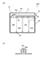
- FIG. 2( a ) is a cross-sectional view schematically illustrating a battery module of the first embodiment.
- FIG. 2( b ) is an enlarged view illustrating a part of FIG. 2( a ).
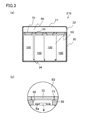
- FIG. 3( a ) is a cross-sectional view schematically illustrating a configuration of a battery module according to a variation of the first embodiment.
- FIG. 3( b ) is an enlarged view illustrating a part of the FIG. 3( a ).
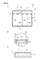
- FIG. 4( a ) is a cross-sectional view schematically illustrating a configuration of a battery module according to another variation of the first embodiment.
- FIG. 4( b ) is an enlarged view of a part of FIG. 4( a ).
- FIG. 4( c ) is a cross-sectional view taken along the line A-A in FIG. 4( a ).
- FIG. 5( a ) is a cross-sectional view illustrating a one-way open valve of FIG. 4( a ) in an opened state.
- FIG. 5( b ) is a side view of the one-way open valve of FIG. 4( a ) in an opened state.
- FIG. 6 is a cross-sectional view schematically illustrating a configuration of a battery module according to another variation of the first embodiment.
- FIG. 7 is a cross-sectional view schematically illustrating a configuration of a battery module according to another variation of the first embodiment.
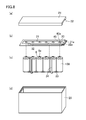
- FIGS. 8( a )- 8 ( d ) are exploded perspective views illustrating a configuration of a battery module having a flat plate made of a circuit board.
- FIG. 9 is a perspective view illustrating the battery module of FIGS. 8( a )- 8 ( d ) after assembly.
- FIGS. 10( a )- 10 ( e ) are exploded perspective views illustrating another configuration of the battery module having the flat plate made of a circuit board.
- FIG. 11 is a perspective view illustrating the battery module of FIGS. 10( a )- 10 ( e ) after assembly.
- FIG. 1 is a cross-sectional view schematically illustrating a configuration of a battery 100 to be used in a battery module according to a first embodiment of the present disclosure.
- a cylindrical lithium ion secondary battery as illustrated in FIG. 1 can be employed as the battery 100 to be used in the battery module of this embodiment.
- a lithium ion secondary battery includes a safety mechanism to release gas to outside the battery when the pressure in the battery increases due to occurrence of, for example, an internal short circuit.
- a specific configuration of the battery 100 will be described below with reference to FIG. 1 .
- an electrode group 4 formed by winding a positive electrode 1 and a negative electrode 2 with a separator 3 interposed between the electrodes 1 and 2 is accommodated in a battery case 7 together with a nonaqueous electrolyte (not shown). Insulating plates 9 and 10 are disposed above and under the electrode group 4 , respectively.
- the positive electrode 1 is joined to a filter 12 via a positive electrode lead 5
- the negative electrode 2 is joined to a bottom portion of the battery case 7 via a negative electrode lead 6 .
- the bottom portion of the battery case 7 also serves as a negative electrode terminal.
- the filter 12 is connected to an inner cap 13 , and a projection of the inner cap 13 is joined to a metallic release valve 14 .
- the release valve 14 is connected to a terminal plate 8 also serving as a positive electrode terminal.
- the terminal plate 8 , the release valve 14 , the inner cap 13 , and the filter 12 collectively seal an opening of the battery case 7 via a gasket 11 .
- the release valve 14 expands toward the terminal plate 8 , and the inner cap 13 and the release valve 14 are disjoined, resulting in an interruption of a current path.
- the release valve 14 ruptures.
- gas produced in the battery 100 is caused to pass via a through hole 12 a of the filter 12 , a through hole 13 a of the inner cap 13 , the ruptured part of the release valve 14 , and an opening portion 8 a of the terminal plate 8 , to be expelled to the outside.
- the safety mechanism for releasing the gas produced in the battery 100 to the outside is not limited to the structure illustrated in FIG. 1 , and may have other structures.
- the position of the opening portion 8 a configured to release the gas produced in the battery 100 to outside the battery 100 is not limited to the position illustrated in FIG. 1 .
- the opening portion 8 a may be located at the center of a protrusion of the terminal plate 8 .
- FIG. 2( a ) is a cross-sectional view schematically illustrating a battery module 200 of this embodiment.
- FIG. 2( b ) is an enlarged view illustrating a part of FIG. 2( a ).
- the battery module 200 has a configuration in which a plurality of the batteries 100 are accommodated in a case 20 .
- Each of the batteries 100 is fixed by ribs 24 formed on a bottom portion 23 of the case 20 at a predetermined position.
- the batteries 100 each include the opening portion 8 a configured to release the gas produced in the associated battery 100 to outside the battery 100 .
- the case 20 is partitioned by a flat plate 30 provided at one side of the batteries 100 (in this embodiment, at the side near the positive electrode terminal 8 ) into an accommodation section 50 configured to accommodate a plurality of the batteries 100 and an exhaust passage 60 configured to expel the gas released from at least one of the opening portions 8 a of the batteries 100 to outside the case 20 .
- each of the opening portions 8 a of the batteries 100 is allowed to communicate with the exhaust passage 60 via a sealed connection passage 40 .
- the opening portions 8 a are each formed in the protrusion 8 (i.e. the terminal plate 8 ) of the battery 100 , and the flat plate 30 is placed in such a manner that each of the protrusions 8 of the batteries 100 is inserted into an associated one of through holes formed in the flat plate 30 and the battery cases are in contact with the flat plate 30 at portions surrounding the protrusions 8 of the batteries 100 .
- Each of the through holes of the flat plate 30 forms an associated one of the connection passages 40 , and a one-way open valve 70 configured to open only along the direction from the opening portion 8 a of the battery 100 to the exhaust passage 60 is provided in each of the connection passages 40 .
- each of the connection passages 40 configured to allow communication between the opening portions 8 a of the batteries 100 and the exhaust passage 60 is blocked by the associated one-way open valve 70 .
- the one-way open valve 70 is opened by a release of gas from the associated one of the opening portions 8 a of the batteries 100 . Since the flat plate 30 is in contact with the one side of the batteries 100 , the connection passages 40 are sealed by the flat plate 30 .
- the accommodation section 50 is also sealed by the flat plate 30 . Therefore, the high-temperature gas having flowed from the opening portion 8 a of the battery 100 into the exhaust passage 60 through the connection passage 40 is not allowed to flow into the accommodation section 50 again.
- a configuration of the one-way open valve 70 of this embodiment will be described below with reference to FIG. 2( b ).
- connection passage 40 configured to connect the opening portion 8 a to the exhaust passage 60 is blocked by the one-way open valve 70 .
- the one-way open valve 70 in a blocking state interrupts the communication between a portion of the connection passage 40 facing the battery 100 and a portion of the connection passage 40 facing the exhaust passage 60 .
- each of the connection passages 40 is constituted of an associated one of through holes formed in the flat plate 30 , and includes a tapered part which is located in a portion of the inner surface and conically tapered toward the battery 100 .
- Each of the one-way open valves 70 has a conical shape corresponding to the shape of the tapered part of the connection passages 40 , and is placed in contact with or pressed into the tapered part. This configuration allows the one-way open valves 70 to open only toward the exhaust passage 60 .
- the one-way open valve 70 provided in the connection passage 40 of the battery 100 releasing the gas is opened toward the exhaust passage 60 , and the gas released from the battery 100 experiencing the failure flows into the exhaust passage 60 through the connection passage 40 .
- the one-way open valves 70 provided in the connection passages 40 of the neighboring batteries remain in blocking states, the gas having flowed into the exhaust passage 60 is expelled to outside the case 20 through the vent 22 without coming into contact with the neighboring batteries 100 . In this manner, a thermal influence which the gas released from the battery 100 experiencing the failure exerts on the neighboring batteries 100 can be reduced.
- the “one-way open valve 70 ” refers to an open valve which is configured to open only along the direction from the opening portion 8 a to the exhaust passage 60 depending on a pressure difference between the portion facing the battery 100 and the portion facing the exhaust passage 60 of the connection passage 40 in which the one-way open valve 70 is provided, and the configuration of the one-way open valve 70 is not limited to a specific one.
- a pressure in the portion facing the battery 100 and a pressure in the portion facing the exhaust passage 60 depend on a pressure of gas released from an associated one of the opening portions 8 a of the batteries 100 when a failure occurs.
- the position at which the one-way open valves 70 is provided in the connection passage 40 is not particularly limited.
- the valve 70 may be provided in an end (an end facing the battery 100 or an end facing the exhaust passage 60 ) of the connection passage 40 , instead of the intermediate portion as illustrated in FIG. 2( b ).
- connection passages 40 is not particularly limited, and any configuration may be applicable as long as each of the connection passages 40 is sealed and allows independent communication between the associated one of the opening portions 8 a of the batteries 100 and the exhaust passage 60 on a battery-by-battery basis.
- the connection passages 40 may be formed integrally with the exhaust passage 60 or the bodies of the batteries 100 .
- the flat plate 30 which is placed in such a manner that the battery cases are in contact with the flat plate 30 at portions surrounding the protrusions 8 (i.e. the positive electrode terminals 8 ) of the batteries 100 , separates the accommodation section 50 configured to accommodate the batteries 100 from the exhaust passage 60 .
- the through holes of the flat plate 30 into which the protrusions 8 of the batteries 100 are inserted serve as the connection passages 40 .
- the flat plate 30 can hermetically isolate the accommodation section 50 from the exhaust passage 60 and seal the connection passages 40 .
- FIG. 3( a ) is a cross-sectional view schematically illustrating a configuration of a battery module 210 according to a variation of the first embodiment.
- FIG. 3( b ) is an enlarged view illustrating a part of the FIG. 3( a ).
- This variation exemplifies a different form of the one-way open valves 70 illustrated in FIG. 2( a ), and has the same configuration as that of the battery module 200 except for the one-way open valves.
- the case 20 is partitioned by the flat plate 30 provided at one side of a plurality of the batteries 100 into the accommodation section 50 configured to accommodate a plurality of the batteries 100 and the exhaust passage 60 configured to expel the gas released from at least one of the opening portions 8 a of the batteries 100 .
- the flat plate 30 is placed in such a manner that each of the protrusions 8 of the batteries 100 is inserted into an associated one of the through holes formed in the flat plate 30 and the battery cases are in contact with the flat plate 30 at portions surrounding the protrusions 8 of the batteries 100 .
- the through holes of the flat plate 30 form the connection passages 40 which allow the communication between the opening portions 8 a of the batteries 100 and the exhaust passage 60 .
- a plate member 70 is placed in contact with the surface of the flat plate 30 facing the exhaust passage 60 so as to close the through holes of the flat plate 30 .
- the plate member 70 has thinner portions 71 formed in regions which are located near the through holes and in contact with the flat plate 30 .
- the thinner portions 71 constitute the one-way open valves.
- a pressure in the portion facing the exhaust passage 60 exceeds a pressure in the portion facing the batteries 100 .
- the thinner portions 71 associated with the neighboring batteries do not rupture even when the predetermined pressure is applied to the plate member 70 .
- the thinner portions 71 formed in this manner can constitute the one-way open valves which can be opened only along the direction from the opening portion 8 a of the battery 100 to the exhaust passage 60 .
- the thinner portions 71 may be formed on both surfaces or one surface of the plate member 70 as long as the thinner portions 71 are located in regions being in contact with the flat plate 30 .
- the shape (for example, a ring shape or a linear shape) and the number of the thinner portions 71 are not particularly limited.
- FIG. 4( a ) is a cross-sectional view schematically illustrating a configuration of a battery module 220 according to another variation of the first embodiment.
- FIG. 4( b ) is an enlarged view of a part of FIG. 4( a ).
- FIG. 4( c ) is a cross-sectional view taken along the line A-A in FIG. 4( a ).
- This variation exemplifies another form of the one-way open valves 70 illustrated in FIG. 3( a ), and has the same configuration as that of the battery module 210 except for the one-way open valves.
- Each of the one-way open valves of this variation further includes a non-rupturable portion 72 formed in a part of the associated one of the thinner portions 71 illustrated in FIGS. 3( a ) and 3 ( b ).
- thinner portions 71 formed on the plate member 70 have, in its part, the non-rupturable portion 72 .
- the non-rupturable portion 72 can be formed, for example, by forming a thinner portion 71 in a ring shape on the surface of the plate member 70 facing the battery 100 and forming another thinner portion 71 in a semi-ring shape lacking a part of its circumference on the surface of the plate member 70 facing the exhaust passage 60 .
- the one-way open valve constituted of the thinner portions 71 having the above described shapes functions in the following manner.
- the associated thinner portions 71 rupture, i.e., the one-way open valve is opened toward the exhaust passage 60 , whereas the non-rupturable portion 72 formed in a part of the thinner portion 71 causes, as illustrated in FIG. 5( a ), the one-way open valve to stay in an opened state with an inclination in a specific direction without being completely separated from the plate member 70 .
- the gas released from the opening portion 8 a of the battery 100 to the exhaust passage 60 through the connection passage 40 can be quickly expelled to outside the case 20 by adjusting the inclination of the opened state such that flow of the gas is directed toward the vent 22 of the exhaust passage 60 .
- the thermal influence exerted on the neighboring batteries 100 can be further reduced.
- the inclination of the opened state can be controlled by modifying, for example, the shapes and/or positions of the thinner portion 71 and the non-rupturable portion 72 .
- FIG. 5( b ) illustrates a member 70 b (for example, a rib) provided on the plate member 70 .
- the member 70 b is formed on a surface 70 a of a region serving as the one-way open valve, and the surface 70 a faces the battery 100 .
- the member 70 b extends parallel to the direction toward the vent 22 of the exhaust passage 60 .
- the one-way open valve including the member 70 b which effectively directs flow of the gas, can cause the gas to be further quickly expelled to outside the case 20 .
- FIG. 6 is a cross-sectional view schematically illustrating a configuration of a battery module 230 according to another variation of the first embodiment.
- This variation exemplifies another form of the connection passages 40 illustrated in FIG. 3( a ), and has the same configuration as that of the battery module 210 except for the connection passages.
- the flat palate 30 has a plurality of hollow members 30 a formed thereon.
- the inner periphery of each of the hollow member 30 a is engaged with the outer periphery of the battery case of an associated one of the batteries 100 .
- the hollow members 30 a form the connection passages 40 .
- the hollow members 30 a may be formed integrally with the flat plate 30 , or may be joined to the flat plate 30 having through holes.
- FIG. 7 is a cross-sectional view schematically illustrating a configuration of a battery module 240 according to another variation of the first embodiment.
- This variation exemplifies another form of the connection passages 40 illustrated in FIG. 3( a ), and has the same configuration as that of the battery module 210 except for the connection passages.
- each of the batteries 100 has a protrusion 8 b extending with an end opened and engaged with the inner surface of an associated one of the through holes of the flat plate 30 .
- the protrusions 8 b form the connection passages 40 .
- the protrusions 8 b may also serve as the positive electrode terminal. In such a case, since each of the protrusions 8 b has an opened end, it is not necessary to provide the opening portions 8 a as illustrated FIG. 1 .
- the flat plate 30 provided in the case 20 separates the accommodation section 50 configured to accommodate the batteries 100 from the exhaust passage 60 configured to expel the gas released from at least one of the opening portions 8 a of the batteries 100 .
- the flat plate 30 may be made of a circuit board having a function of electrically connecting the batteries 100 to one another.
- FIGS. 8( a )- 8 ( d ) are exploded perspective views illustrating a configuration of a battery module having the flat plate 30 made of a circuit board.
- FIG. 9 is a perspective view illustrating an assembled battery module 300 . Note that the connecting structure of the batteries 100 which is described in this variation imposes no limitation on the mechanism for expelling gas described in the first embodiment.
- the circuit board 30 has through holes 40 formed therein, and a positive electrode connector 31 and a negative electrode connector 32 are formed on a surface of the circuit board 30 .
- the positive electrode connector 31 has openings 40 a formed at the positions corresponding to the through holes 40 .
- Each of protrusions of the positive electrode terminals 8 of the batteries 100 is inserted into an associated one of the through holes 40 of the circuit board 30 to be connected to the positive electrode connector 31 formed on the circuit board 30 .
- the negative electrode terminals of the batteries 100 are connected in parallel by a negative electrode bus bar 33 , and conductor parts 34 extending from portions of the negative electrode bus bar 33 connect the negative electrode terminals to the positive electrode connector 32 formed on the circuit board 30 .
- the batteries 100 are connected in parallel via the positive and negative electrode connecters 31 and 32 formed on the circuit board 30 .
- an end 31 a of the positive electrode connecter 31 and an end 32 a of the negative electrode connector 32 protrude outside from the vent 22 formed on a lid 21 of the case 20 to serve as external terminals of the battery module 300 .
- connection passages 40 are constituted of the through holes 40 of the circuit board 30 and the openings 40 a of the positive electrode connector 31 .
- FIGS. 10( a )- 10 ( e ) are exploded perspective views illustrating another configuration of a battery module having the flat plate 30 made of a circuit board.
- FIG. 11 is a perspective view illustrating an assembled battery module 310 .
- a plurality of battery assemblies 110 each of which includes a plurality of batteries 100 arranged in a line, are connected in parallel.
- the connecting structure of the batteries 100 is the same as the structure illustrated in FIGS. 8( a ) and 8 ( b ), except that adjacent ones of the battery assemblies 110 are connected in series by connecting the positive and negative electrode connectors 31 and 32 illustrated in FIG. 10( b ) to each other.
- the present disclosure has been described with the above preferred embodiment. Note that the descriptions of the embodiment are not to limit the present disclosure, and various changes and modifications may be made.
- lithium ion secondary batteries are used as the batteries 100 constituting the battery modules in the above embodiment, other types of secondary batteries (e.g., nickel-hydrogen batteries) may also be used.
- the battery 100 may be a cylindrical battery, a rectangular battery, or a laminated battery.
- the one-way open valve may be a restorable valve.
- the open valve may be made of an elastic body such as resin, rubber or a metallic coil such that the open valve restores a sealing state when a pressure applied to the valve falls below a predetermined value.
- the valve may be made of a shape-memory alloy such that the valve restores a predetermined shape when the valve is cooled after the high-temperature gas has passed therethrough.
- the battery module of the present disclosure can be suitably used, for example, as power supplies for mobile electronic devices such as personal computers and cellular phones, or as power supplies for driving power tools or electric vehicles.
Landscapes
- Chemical & Material Sciences (AREA)
- Chemical Kinetics & Catalysis (AREA)
- Electrochemistry (AREA)
- General Chemical & Material Sciences (AREA)
- Gas Exhaust Devices For Batteries (AREA)
- Battery Mounting, Suspending (AREA)
- Connection Of Batteries Or Terminals (AREA)
Applications Claiming Priority (3)
| Application Number | Priority Date | Filing Date | Title |
|---|---|---|---|
| JP2010-177639 | 2010-08-06 | ||
| JP2010177639 | 2010-08-06 | ||
| PCT/JP2011/003047 WO2012017586A1 (ja) | 2010-08-06 | 2011-05-31 | 電池モジュール |
Publications (2)
| Publication Number | Publication Date |
|---|---|
| US20130095356A1 US20130095356A1 (en) | 2013-04-18 |
| US9231237B2 true US9231237B2 (en) | 2016-01-05 |
Family
ID=45559112
Family Applications (1)
| Application Number | Title | Priority Date | Filing Date |
|---|---|---|---|
| US13/807,672 Active 2031-07-09 US9231237B2 (en) | 2010-08-06 | 2011-05-31 | Cell module |
Country Status (5)
| Country | Link |
|---|---|
| US (1) | US9231237B2 (ja) |
| JP (1) | JP5589078B2 (ja) |
| KR (1) | KR20130043154A (ja) |
| CN (1) | CN103081164B (ja) |
| WO (1) | WO2012017586A1 (ja) |
Cited By (5)
| Publication number | Priority date | Publication date | Assignee | Title |
|---|---|---|---|---|
| US10193113B2 (en) | 2013-07-25 | 2019-01-29 | Johnson Controls Techology Company | Vent adapter for lead-acid battery systems |
| USD886060S1 (en) | 2018-01-19 | 2020-06-02 | Cps Technology Holdings, Llc | Battery vent adapter |
| WO2022028857A1 (en) | 2020-08-07 | 2022-02-10 | Jt International Sa | Electronic cigarette device with temperature-activated battery vent port |
| EP4224603A4 (en) * | 2020-09-30 | 2024-04-24 | Panasonic Intellectual Property Management Co., Ltd. | Battery pack |
| US12278387B2 (en) | 2019-11-08 | 2025-04-15 | Contemporary Amperex Technology (Hong Kong) Limited | Battery pack and apparatus |
Families Citing this family (107)
| Publication number | Priority date | Publication date | Assignee | Title |
|---|---|---|---|---|
| US20150125720A1 (en) * | 2012-08-09 | 2015-05-07 | Sanyo Electric Co., Ltd. | Power source device, electric vehicle provided with same, and electricity storage device |
| JP2014139705A (ja) * | 2013-01-21 | 2014-07-31 | Kubota Corp | 自動販売機 |
| CN104995762A (zh) * | 2013-02-14 | 2015-10-21 | 三洋电机株式会社 | 电池块 |
| DE102013207356A1 (de) * | 2013-04-23 | 2014-10-23 | Elringklinger Ag | Verfahren zum Herstellen eines Zellkontaktierungssystems für eine elektrochemische Vorrichtung und Zellkontaktierungssystem |
| JP2015018706A (ja) * | 2013-07-11 | 2015-01-29 | 株式会社豊田自動織機 | 蓄電装置モジュール |
| US10347894B2 (en) | 2017-01-20 | 2019-07-09 | Tesla, Inc. | Energy storage system |
| AT515312B1 (de) * | 2014-01-28 | 2015-08-15 | Avl List Gmbh | Batteriemodul |
| JP6283964B2 (ja) | 2014-02-07 | 2018-02-28 | パナソニックIpマネジメント株式会社 | 電池モジュール |
| DE102014207403A1 (de) * | 2014-04-17 | 2015-10-22 | Robert Bosch Gmbh | Batterieeinheit mit einer Aufnahmeeinrichtung und einer Mehrzahl von elektrochemischen Zellen sowie Batteriemodul mit einer Mehrzahl von solchen Batterieeinheiten |
| US9614210B2 (en) | 2014-09-30 | 2017-04-04 | Johnson Controls Technology Company | Battery module vent system and method |
| US10141554B2 (en) * | 2015-02-10 | 2018-11-27 | Vertiv Energy Systems, Inc. | Enclosures and methods for removing hydrogen gas from enclosures |
| US10601002B2 (en) * | 2015-03-27 | 2020-03-24 | Sanyo Electric Co., Ltd. | Cylindrical battery and method for producing the same |
| KR101954043B1 (ko) * | 2015-10-05 | 2019-03-04 | 닛산 지도우샤 가부시키가이샤 | 배터리 팩의 압력 개방 기구 |
| CN108604653B (zh) * | 2016-01-26 | 2021-11-12 | 三洋电机株式会社 | 电池组 |
| US20180138478A1 (en) * | 2016-11-14 | 2018-05-17 | Anhui Xinen Technology Co., Ltd. | Alleviating explosion propagation in a battery module |
| CN114824608B (zh) * | 2016-11-30 | 2024-10-25 | 松下知识产权经营株式会社 | 电池模块 |
| KR102085343B1 (ko) * | 2016-12-05 | 2020-03-05 | 주식회사 엘지화학 | 원통형 이차전지 모듈 |
| DE102016225057A1 (de) | 2016-12-15 | 2018-06-21 | Bayerische Motoren Werke Aktiengesellschaft | Batterieeinheit für eine Traktionsbatterie und Traktionsbatterie |
| JP6920661B2 (ja) * | 2016-12-27 | 2021-08-18 | パナソニックIpマネジメント株式会社 | 電池モジュール |
| CN106654114A (zh) * | 2017-01-22 | 2017-05-10 | 北京新能源汽车股份有限公司 | 一种动力电池结构及汽车 |
| CN107093686B (zh) * | 2017-04-28 | 2020-04-14 | 北京新能源汽车股份有限公司 | 电池包和车辆 |
| DE102017214289A1 (de) * | 2017-08-16 | 2019-02-21 | Robert Bosch Gmbh | Batteriemodul und Fahrzeug mit dem Batteriemodul |
| JP7010671B2 (ja) * | 2017-11-15 | 2022-01-26 | スカッドエレクトロニクスジャパン株式会社 | リチウムイオン電池モジュール |
| JP6965446B2 (ja) * | 2018-06-20 | 2021-11-10 | ビークルエナジージャパン株式会社 | 電池モジュールおよび電池パック |
| DE102018210152A1 (de) | 2018-06-21 | 2019-12-24 | Bayerische Motoren Werke Aktiengesellschaft | Fahrzeug mit einem Hochvoltspeicher |
| DE102018210151A1 (de) | 2018-06-21 | 2019-12-24 | Bayerische Motoren Werke Aktiengesellschaft | Fahrzeug mit einem Hochvoltspeicher |
| JP6676705B2 (ja) * | 2018-06-25 | 2020-04-08 | 株式会社Subaru | バッテリモジュール |
| DE102018211316A1 (de) * | 2018-07-09 | 2020-01-09 | Bayerische Motoren Werke Aktiengesellschaft | Fahrzeug mit einem Hochvoltspeicher |
| DE102018122080A1 (de) * | 2018-09-11 | 2020-03-12 | Webasto SE | Batteriemodul und Verfahren zum Herstellen eines Batteriemoduls |
| DE102018125446A1 (de) * | 2018-10-15 | 2020-04-16 | Webasto SE | Batteriegehäuse mit Funkenfalle |
| CN113273024A (zh) * | 2018-11-13 | 2021-08-17 | 瑞维安知识产权控股有限责任公司 | 电池单元组热失控缓解 |
| DE102018132292A1 (de) * | 2018-12-14 | 2020-06-18 | Webasto SE | Batteriegehäuse für ein Kraftfahrzeug |
| US12266809B2 (en) * | 2019-02-15 | 2025-04-01 | Panasonic Holdings Corporation | Power supply device |
| EP3959756B8 (en) | 2019-04-25 | 2024-02-28 | SoftBank Corp. | Battery pack design with protection from thermal runaway |
| CN110148692A (zh) * | 2019-05-10 | 2019-08-20 | 北京新能源汽车股份有限公司 | 电池模组及具有其的车辆 |
| JP7461723B2 (ja) * | 2019-07-30 | 2024-04-04 | パナソニックエナジー株式会社 | 電源装置 |
| JP7461722B2 (ja) * | 2019-07-30 | 2024-04-04 | パナソニックエナジー株式会社 | 電源装置 |
| US11283121B1 (en) | 2019-11-27 | 2022-03-22 | Zoox, Inc. | Battery thermal mitigation using coolant |
| US12194887B1 (en) | 2019-11-27 | 2025-01-14 | Zoox, Inc. | Control of cooling system for battery thermal mitigation |
| US11316230B1 (en) * | 2019-11-27 | 2022-04-26 | Zoox, Inc. | Battery thermal mitigation venting |
| US20230006302A1 (en) * | 2019-12-03 | 2023-01-05 | Sanyo Electric Co., Ltd. | Battery pack |
| CN211404606U (zh) * | 2020-03-20 | 2020-09-01 | 中航锂电(洛阳)有限公司 | 一种电池模组的安全结构及电池包 |
| US11605861B2 (en) * | 2020-04-08 | 2023-03-14 | Sk On Co., Ltd. | Battery module with flame or gas discharge path |
| KR102665192B1 (ko) * | 2020-04-29 | 2024-05-09 | 주식회사 엘지에너지솔루션 | 전지 팩 및 이를 포함하는 디바이스 |
| EP3910699A1 (en) * | 2020-05-12 | 2021-11-17 | Samsung SDI Co., Ltd. | Battery system and vehicle including the battery system |
| US20210359374A1 (en) * | 2020-05-12 | 2021-11-18 | Samsung Sdi Co., Ltd. | Battery system and vehicle including the battery system |
| DE102020113086A1 (de) * | 2020-05-14 | 2021-11-18 | Kautex Textron Gmbh & Co. Kg | Traktionsbatterie aufweisend ein Leitmittel für einen Fluidvolumenstrom und Kraftfahrzeug |
| CN111584978A (zh) * | 2020-06-22 | 2020-08-25 | 昆山宝创新能源科技有限公司 | 电池模组 |
| JP7543005B2 (ja) * | 2020-06-22 | 2024-09-02 | パナソニックエナジー株式会社 | 電池パック |
| CN111584791A (zh) * | 2020-06-22 | 2020-08-25 | 昆山宝创新能源科技有限公司 | 电池模组 |
| CN111584979A (zh) * | 2020-06-22 | 2020-08-25 | 昆山宝创新能源科技有限公司 | 电池模组 |
| CN113871789A (zh) * | 2020-06-30 | 2021-12-31 | 福特全球技术公司 | 用于电气化车辆的电池组通风组件及系统 |
| CN114175363B (zh) | 2020-07-10 | 2024-02-20 | 宁德时代新能源科技股份有限公司 | 电池及其相关装置、制备方法和制备设备 |
| CN114175350B (zh) * | 2020-07-10 | 2023-12-22 | 宁德时代新能源科技股份有限公司 | 热失控检测的方法和电池管理系统 |
| EP3958378B1 (en) | 2020-07-10 | 2023-12-13 | Contemporary Amperex Technology Co., Limited | Battery, electric device, and method and device for preparing battery |
| EP3965211B1 (en) | 2020-07-10 | 2023-11-29 | Contemporary Amperex Technology Co., Limited | Box body for battery, battery, electric device, and method and device for preparing battery |
| JP7429719B2 (ja) | 2020-07-10 | 2024-02-08 | 寧徳時代新能源科技股▲分▼有限公司 | 電池、電力消費機器、電池の製造方法及び装置 |
| WO2022006894A1 (zh) * | 2020-07-10 | 2022-01-13 | 宁德时代新能源科技股份有限公司 | 电池及其相关装置、制备方法和制备设备 |
| KR102908425B1 (ko) * | 2020-07-20 | 2026-01-06 | 에스케이온 주식회사 | 배터리 모듈 |
| TWI890834B (zh) * | 2020-08-04 | 2025-07-21 | 南韓商Lg新能源股份有限公司 | 電池模組、包括其之電池組以及車輛 |
| CN112054145B (zh) * | 2020-09-27 | 2022-10-28 | 无锡铃派科技有限公司 | 一种电动车用电池盒定位机构 |
| FR3114917B1 (fr) * | 2020-10-06 | 2023-05-12 | Commissariat Energie Atomique | Carter de batterie |
| EP3982473A1 (de) | 2020-10-12 | 2022-04-13 | Andreas Stihl AG & Co. KG | Akkupack, bearbeitungssystem und verfahren zur herstellung eines akkupacks |
| FR3115935B1 (fr) * | 2020-10-29 | 2023-07-14 | Commissariat Energie Atomique | Dispositif de sécurité adaptable sur une cellule électrochimique |
| DE102020128756A1 (de) | 2020-11-02 | 2022-05-05 | Bayerische Motoren Werke Aktiengesellschaft | Batterie mit einem Schutzelement und Kraftfahrzeug |
| CN112688019B (zh) * | 2020-12-25 | 2022-10-14 | 中国第一汽车股份有限公司 | 一种动力电池热流泄放装置及动力电池热流泄放方法 |
| CN114765296A (zh) * | 2021-01-13 | 2022-07-19 | 福特全球技术公司 | 包括排气通道的电池组 |
| KR102718427B1 (ko) * | 2021-02-02 | 2024-10-16 | 주식회사 엘지에너지솔루션 | 셀 단위 가스계 소화약제 가이드 날개를 적용한 배터리 모듈 및 이를 포함하는 배터리 랙과 에너지 저장장치 |
| US12431560B2 (en) * | 2021-02-17 | 2025-09-30 | Samsung Sdi Co., Ltd. | Battery system and vehicle including the battery system |
| BE1029162B1 (nl) * | 2021-03-04 | 2022-10-03 | Bebat Vzw | Vat voor het transport en/of de opslag van batterijen en het gebruik van een dergelijk vat |
| CN115398721B (zh) * | 2021-03-15 | 2023-11-03 | 宁德时代新能源科技股份有限公司 | 电池、用电装置、制备电池的方法和装置 |
| CN115668613B (zh) * | 2021-03-31 | 2024-01-19 | 宁德时代新能源科技股份有限公司 | 电池的箱体、电池、用电设备、制备箱体的方法和装置 |
| KR102861602B1 (ko) * | 2021-06-21 | 2025-09-17 | 주식회사 엘지에너지솔루션 | 전지 모듈 및 이를 포함하는 전지 팩 |
| DE102021116122A1 (de) | 2021-06-22 | 2022-12-22 | Bayerische Motoren Werke Aktiengesellschaft | Elektrochemischer Energiespeicher |
| DE102021116353A1 (de) | 2021-06-24 | 2022-12-29 | Bayerische Motoren Werke Aktiengesellschaft | Gehäuseteil zur Entgasung einer Speicherzelle eines Energiespeichers |
| US20220416359A1 (en) * | 2021-06-24 | 2022-12-29 | Rivian Ip Holdings, Llc | Directional venting cover for a battery system |
| DE102021118068A1 (de) | 2021-07-13 | 2023-01-19 | Elringklinger Ag | Abdeckung für ein Batteriemodul oder für einen Batteriespeicher |
| DE102021208346A1 (de) | 2021-08-02 | 2023-02-02 | Volkswagen Aktiengesellschaft | Akkumulator für ein Kraftfahrzeug und Kraftfahrzeug mit Akkumulator |
| US20240356130A1 (en) | 2021-09-28 | 2024-10-24 | Panasonic Intellectual Property Management Co., Ltd. | Battery pack |
| KR102757170B1 (ko) * | 2021-09-30 | 2025-01-21 | 에스케이온 주식회사 | 배터리 모듈 또는 이를 포함하는 배터리 팩 |
| EP4411956A4 (en) * | 2021-09-30 | 2025-01-15 | Panasonic Intellectual Property Management Co., Ltd. | ELECTRICAL ENERGY STORAGE MODULE |
| CN113644360B (zh) * | 2021-10-19 | 2021-12-28 | 嘉兴模度新能源有限公司 | 一种具有热疏导功能的电池箱、热疏导结构及方法 |
| CN216850203U (zh) * | 2021-11-08 | 2022-06-28 | 宁德时代新能源科技股份有限公司 | 电池箱、电池及用电装置 |
| DE102021214245A1 (de) * | 2021-12-13 | 2023-06-15 | Audi Aktiengesellschaft | Abdeckelement in Sandwichbauweise mit aufschmelzbarer Zwischenlage für ein Batteriegehäuse, Batteriegehäuse und Kraftfahrzeug |
| JPWO2023136282A1 (ja) * | 2022-01-17 | 2023-07-20 | ||
| EP4475313A4 (en) * | 2022-01-31 | 2025-04-30 | Panasonic Intellectual Property Management Co., Ltd. | Electricity storage pack |
| EP4228073A1 (de) * | 2022-02-10 | 2023-08-16 | MAGNA STEYR Fahrzeugtechnik GmbH & Co KG | Kraftfahrzeugbatterie mit gasableitelementen |
| KR20230123695A (ko) * | 2022-02-17 | 2023-08-24 | 주식회사 엘지에너지솔루션 | 전지 모듈 및 이를 포함하는 전지 팩 |
| CN118975030A (zh) * | 2022-03-14 | 2024-11-15 | 松下知识产权经营株式会社 | 电池组 |
| CN116937046B (zh) * | 2022-03-31 | 2026-02-06 | 宁德新能源科技有限公司 | 一种电池组及用电装置 |
| CN119174041A (zh) * | 2022-06-15 | 2024-12-20 | 株式会社 Lg新能源 | 二次电池组 |
| KR102913957B1 (ko) * | 2022-07-19 | 2026-01-16 | 주식회사 엘지에너지솔루션 | 배터리, 이를 포함하는 배터리 팩, 그리고 배터리 팩을 포함하는 자동차 |
| CN119174039A (zh) * | 2022-07-19 | 2024-12-20 | 株式会社Lg新能源 | 电池、包括电池的电池组以及包括电池组的车辆 |
| JP7749816B2 (ja) * | 2022-07-20 | 2025-10-06 | エルジー エナジー ソリューション リミテッド | バッテリパックおよびこれを含むデバイス |
| US20240063465A1 (en) * | 2022-08-19 | 2024-02-22 | GM Global Technology Operations LLC | Cold-plate design for thermal runaway mitigation in a battery module |
| NL2033231B1 (en) * | 2022-10-04 | 2024-04-16 | Storm Group B V | Passive safety system for a battery module |
| US12068498B1 (en) * | 2022-10-07 | 2024-08-20 | Archer Aviation Inc. | Systems and methods for improved battery assemblies for EVTOL aircraft |
| US20240204342A1 (en) * | 2022-12-15 | 2024-06-20 | Polestar Performance Ab | Methods and systems for burst valve battery cell ventilation |
| US12603380B2 (en) * | 2023-02-01 | 2026-04-14 | Ford Global Technologies, Llc | Battery pack including hinged flap for release of vent gas |
| DE102023104810B4 (de) * | 2023-02-28 | 2025-05-15 | Man Truck & Bus Se | Elektrischer Energiespeicher aufweisend eine Abdeckplatte mit strukturgeschwächten Plattenbereichen |
| CN119731859A (zh) * | 2023-06-23 | 2025-03-28 | 日本汽车能源株式会社 | 电池 |
| KR20250054581A (ko) * | 2023-10-16 | 2025-04-23 | 주식회사 엘지에너지솔루션 | 배터리 팩 |
| US12592450B2 (en) * | 2023-12-06 | 2026-03-31 | GM Global Technology Operations LLC | Battery system with diverter assembly for thermal propagation protection |
| KR20250106021A (ko) * | 2024-01-02 | 2025-07-09 | 주식회사 엘지에너지솔루션 | 배터리 팩 및 이를 포함하는 자동차 |
| DE102024102031A1 (de) * | 2024-01-24 | 2025-07-24 | Bayerische Motoren Werke Aktiengesellschaft | Batteriemodul für eine Traktionsbatterie eines Kraftfahrzeugs sowie Kraftfahrzeug |
| EP4606626A1 (en) * | 2024-02-22 | 2025-08-27 | Volvo Truck Corporation | Battery module with gas venting channel |
| CN121149569A (zh) * | 2024-06-13 | 2025-12-16 | 宁德时代新能源科技股份有限公司 | 一种电池、用电设备和箱体 |
Citations (10)
| Publication number | Priority date | Publication date | Assignee | Title |
|---|---|---|---|---|
| US2294427A (en) * | 1940-11-29 | 1942-09-01 | Arthur E Spicer | Battery |
| JP2002008603A (ja) | 2000-04-21 | 2002-01-11 | Toyota Motor Corp | 電源装置 |
| JP2003100267A (ja) | 2001-09-25 | 2003-04-04 | Yazaki Corp | 電源装置 |
| JP2004039582A (ja) | 2002-07-08 | 2004-02-05 | Toyota Motor Corp | 集合電池 |
| US20040091769A1 (en) * | 2002-10-31 | 2004-05-13 | Katsuhiko Kawabata | Battery pack |
| JP2007027011A (ja) | 2005-07-20 | 2007-02-01 | Sanyo Electric Co Ltd | 電源装置 |
| WO2008026854A1 (en) * | 2006-08-28 | 2008-03-06 | Lg Chem, Ltd. | Secondary battery including one-way exhaust valve |
| WO2009110167A1 (ja) * | 2008-03-04 | 2009-09-11 | パナソニック株式会社 | 電池モジュールおよびそれらを用いた電池パック |
| JP2010287514A (ja) | 2009-06-12 | 2010-12-24 | Sanyo Electric Co Ltd | 電源装置及びこれを備える車両 |
| JP2011065906A (ja) | 2009-09-18 | 2011-03-31 | Panasonic Corp | 電池モジュール |
-
2011
- 2011-05-31 US US13/807,672 patent/US9231237B2/en active Active
- 2011-05-31 JP JP2012527568A patent/JP5589078B2/ja active Active
- 2011-05-31 CN CN201180038947.6A patent/CN103081164B/zh active Active
- 2011-05-31 KR KR1020137000937A patent/KR20130043154A/ko not_active Ceased
- 2011-05-31 WO PCT/JP2011/003047 patent/WO2012017586A1/ja not_active Ceased
Patent Citations (12)
| Publication number | Priority date | Publication date | Assignee | Title |
|---|---|---|---|---|
| US2294427A (en) * | 1940-11-29 | 1942-09-01 | Arthur E Spicer | Battery |
| JP2002008603A (ja) | 2000-04-21 | 2002-01-11 | Toyota Motor Corp | 電源装置 |
| JP2003100267A (ja) | 2001-09-25 | 2003-04-04 | Yazaki Corp | 電源装置 |
| JP2004039582A (ja) | 2002-07-08 | 2004-02-05 | Toyota Motor Corp | 集合電池 |
| US20040091769A1 (en) * | 2002-10-31 | 2004-05-13 | Katsuhiko Kawabata | Battery pack |
| JP2007027011A (ja) | 2005-07-20 | 2007-02-01 | Sanyo Electric Co Ltd | 電源装置 |
| WO2008026854A1 (en) * | 2006-08-28 | 2008-03-06 | Lg Chem, Ltd. | Secondary battery including one-way exhaust valve |
| WO2009110167A1 (ja) * | 2008-03-04 | 2009-09-11 | パナソニック株式会社 | 電池モジュールおよびそれらを用いた電池パック |
| US20100266880A1 (en) * | 2008-03-04 | 2010-10-21 | Panasonic Corporation | Battery module and battery pack using said battery module |
| JP2010287514A (ja) | 2009-06-12 | 2010-12-24 | Sanyo Electric Co Ltd | 電源装置及びこれを備える車両 |
| JP2011065906A (ja) | 2009-09-18 | 2011-03-31 | Panasonic Corp | 電池モジュール |
| US20120164490A1 (en) | 2009-09-18 | 2012-06-28 | Toshiki Itoi | Battery module |
Non-Patent Citations (1)
| Title |
|---|
| International Search Report issued in International Application No. PCT/JP2011/003047 dated Aug. 30, 2011. |
Cited By (6)
| Publication number | Priority date | Publication date | Assignee | Title |
|---|---|---|---|---|
| US10193113B2 (en) | 2013-07-25 | 2019-01-29 | Johnson Controls Techology Company | Vent adapter for lead-acid battery systems |
| US11799165B2 (en) | 2013-07-25 | 2023-10-24 | Cps Technology Holdings Llc | Vent adapter for lead-acid battery systems |
| USD886060S1 (en) | 2018-01-19 | 2020-06-02 | Cps Technology Holdings, Llc | Battery vent adapter |
| US12278387B2 (en) | 2019-11-08 | 2025-04-15 | Contemporary Amperex Technology (Hong Kong) Limited | Battery pack and apparatus |
| WO2022028857A1 (en) | 2020-08-07 | 2022-02-10 | Jt International Sa | Electronic cigarette device with temperature-activated battery vent port |
| EP4224603A4 (en) * | 2020-09-30 | 2024-04-24 | Panasonic Intellectual Property Management Co., Ltd. | Battery pack |
Also Published As
| Publication number | Publication date |
|---|---|
| JP5589078B2 (ja) | 2014-09-10 |
| CN103081164A (zh) | 2013-05-01 |
| WO2012017586A1 (ja) | 2012-02-09 |
| CN103081164B (zh) | 2015-11-25 |
| US20130095356A1 (en) | 2013-04-18 |
| JPWO2012017586A1 (ja) | 2013-09-19 |
| KR20130043154A (ko) | 2013-04-29 |
Similar Documents
| Publication | Publication Date | Title |
|---|---|---|
| US9231237B2 (en) | Cell module | |
| CN103247817B (zh) | 可再充电电池 | |
| EP2445032B1 (en) | Battery module | |
| EP2860787B1 (en) | Battery module comprising venting guidance portion | |
| US9178191B2 (en) | Battery module | |
| EP2482361B1 (en) | Battery pack | |
| EP2339672B1 (en) | Battery module and battery pack using same | |
| CN100544068C (zh) | 电池模块 | |
| US20120225335A1 (en) | Battery module | |
| CN102484235A (zh) | 电池模块 | |
| KR20150066077A (ko) | 배터리 모듈 | |
| US10290852B2 (en) | Battery pack including an interlock switch | |
| KR19990031352A (ko) | 전지의 안전장치 | |
| US20090233169A1 (en) | Battery module and battery pack | |
| US10720621B2 (en) | Battery module | |
| JP2021052020A (ja) | 二次電池および二次電池集合体 | |
| KR101307386B1 (ko) | 전지팩 안전장치 | |
| CN222940163U (zh) | 电池单体、电池模组和用电设备 | |
| KR100788558B1 (ko) | 팩 전지 | |
| KR20250165026A (ko) | 커넥터 및 이를 포함하는 배터리 팩 | |
| CN120073169A (zh) | 蓄电设备模块 |
Legal Events
| Date | Code | Title | Description |
|---|---|---|---|
| AS | Assignment |
Owner name: PANASONIC CORPORATION, JAPAN Free format text: ASSIGNMENT OF ASSIGNORS INTEREST;ASSIGNORS:SHIMIZU, KEISUKE;YOKOYAMA, TOMOHIKO;FUJIKAWA, MASATO;AND OTHERS;SIGNING DATES FROM 20121122 TO 20121123;REEL/FRAME:030073/0648 |
|
| AS | Assignment |
Owner name: PANASONIC INTELLECTUAL PROPERTY MANAGEMENT CO., LTD., JAPAN Free format text: ASSIGNMENT OF ASSIGNORS INTEREST;ASSIGNOR:PANASONIC CORPORATION;REEL/FRAME:034194/0143 Effective date: 20141110 Owner name: PANASONIC INTELLECTUAL PROPERTY MANAGEMENT CO., LT Free format text: ASSIGNMENT OF ASSIGNORS INTEREST;ASSIGNOR:PANASONIC CORPORATION;REEL/FRAME:034194/0143 Effective date: 20141110 |
|
| STCF | Information on status: patent grant |
Free format text: PATENTED CASE |
|
| MAFP | Maintenance fee payment |
Free format text: PAYMENT OF MAINTENANCE FEE, 4TH YEAR, LARGE ENTITY (ORIGINAL EVENT CODE: M1551); ENTITY STATUS OF PATENT OWNER: LARGE ENTITY Year of fee payment: 4 |
|
| AS | Assignment |
Owner name: PANASONIC INTELLECTUAL PROPERTY MANAGEMENT CO., LTD., JAPAN Free format text: CORRECTIVE ASSIGNMENT TO CORRECT THE ERRONEOUSLY FILED APPLICATION NUMBERS 13/384239, 13/498734, 14/116681 AND 14/301144 PREVIOUSLY RECORDED ON REEL 034194 FRAME 0143. ASSIGNOR(S) HEREBY CONFIRMS THE ASSIGNMENT;ASSIGNOR:PANASONIC CORPORATION;REEL/FRAME:056788/0362 Effective date: 20141110 |
|
| MAFP | Maintenance fee payment |
Free format text: PAYMENT OF MAINTENANCE FEE, 8TH YEAR, LARGE ENTITY (ORIGINAL EVENT CODE: M1552); ENTITY STATUS OF PATENT OWNER: LARGE ENTITY Year of fee payment: 8 |