WO2009110167A1 - 電池モジュールおよびそれらを用いた電池パック - Google Patents
電池モジュールおよびそれらを用いた電池パック Download PDFInfo
- Publication number
- WO2009110167A1 WO2009110167A1 PCT/JP2009/000194 JP2009000194W WO2009110167A1 WO 2009110167 A1 WO2009110167 A1 WO 2009110167A1 JP 2009000194 W JP2009000194 W JP 2009000194W WO 2009110167 A1 WO2009110167 A1 WO 2009110167A1
- Authority
- WO
- WIPO (PCT)
- Prior art keywords
- battery
- partition member
- battery module
- casing
- module according
- Prior art date
Links
Images


Classifications
-
- H—ELECTRICITY
- H01—ELECTRIC ELEMENTS
- H01M—PROCESSES OR MEANS, e.g. BATTERIES, FOR THE DIRECT CONVERSION OF CHEMICAL ENERGY INTO ELECTRICAL ENERGY
- H01M50/00—Constructional details or processes of manufacture of the non-active parts of electrochemical cells other than fuel cells, e.g. hybrid cells
- H01M50/20—Mountings; Secondary casings or frames; Racks, modules or packs; Suspension devices; Shock absorbers; Transport or carrying devices; Holders
- H01M50/204—Racks, modules or packs for multiple batteries or multiple cells
- H01M50/207—Racks, modules or packs for multiple batteries or multiple cells characterised by their shape
- H01M50/213—Racks, modules or packs for multiple batteries or multiple cells characterised by their shape adapted for cells having curved cross-section, e.g. round or elliptic
-
- H—ELECTRICITY
- H01—ELECTRIC ELEMENTS
- H01M—PROCESSES OR MEANS, e.g. BATTERIES, FOR THE DIRECT CONVERSION OF CHEMICAL ENERGY INTO ELECTRICAL ENERGY
- H01M50/00—Constructional details or processes of manufacture of the non-active parts of electrochemical cells other than fuel cells, e.g. hybrid cells
- H01M50/40—Separators; Membranes; Diaphragms; Spacing elements inside cells
-
- Y—GENERAL TAGGING OF NEW TECHNOLOGICAL DEVELOPMENTS; GENERAL TAGGING OF CROSS-SECTIONAL TECHNOLOGIES SPANNING OVER SEVERAL SECTIONS OF THE IPC; TECHNICAL SUBJECTS COVERED BY FORMER USPC CROSS-REFERENCE ART COLLECTIONS [XRACs] AND DIGESTS
- Y02—TECHNOLOGIES OR APPLICATIONS FOR MITIGATION OR ADAPTATION AGAINST CLIMATE CHANGE
- Y02E—REDUCTION OF GREENHOUSE GAS [GHG] EMISSIONS, RELATED TO ENERGY GENERATION, TRANSMISSION OR DISTRIBUTION
- Y02E60/00—Enabling technologies; Technologies with a potential or indirect contribution to GHG emissions mitigation
- Y02E60/10—Energy storage using batteries
Definitions
- the present invention relates to a battery module that does not affect other batteries even if a problem such as heat generation occurs in the battery, and a battery pack using them.
- Lithium-ion secondary batteries are lightweight, have high electromotive force, and high energy density, so they can be used in various types of mobile phones, digital cameras, video cameras, and notebook computers.
- power sources for driving portable electronic devices and mobile communication devices There is an increasing demand for power sources for driving portable electronic devices and mobile communication devices.
- battery modules that can obtain desired voltages and capacities by combining them as power sources for driving motors of automobiles and the like have also been developed. ing.
- Batteries such as those described above may be overcharged, or gas generated by an internal short circuit or an external short circuit may increase the internal pressure of the battery, and in some cases, the battery case may burst. Therefore, in general, these batteries are provided with a vent mechanism for venting gas or an exhaust hole.
- a battery that can be charged and discharged a filter unit that adsorbs a flammable substance, a battery and a filter unit, which can prevent smoke and ignition of the battery, are provided.
- An example of a battery pack is disclosed that includes an outer member provided with a discharge hole that covers and discharges the contents purified by passing through the filter unit to the outside (see, for example, Patent Document 1).
- the battery module shown in patent document 2 can perform the connection between batteries stably by accommodating a battery in a battery accommodating part separately. Further, even when subjected to vibration or impact, the battery can be held in the battery housing portion without rattling. Further, it is shown that a cooling passage is secured by a heat radiating hole provided in the height direction of the battery and uniform cooling can be performed. However, there is no description about preventing an influence on the surrounding batteries when one battery abnormally generates heat and ignites or ruptures. JP 2006-228610 A JP 2003-162993 A
- the battery module of the present invention includes a plurality of batteries having a first casing, a second casing, and an exhaust hole accommodated between the first casing and the second casing, and at least one of the first casing and the second casing.
- it has the structure which provided the 1st partition member which accommodates a battery separately in the position facing the exhaust hole of a battery.
- This configuration prevents flames caused by the ignition of gas ejected from the exhaust hole of the defective battery from being caught by the first partition member and preventing direct flames from hitting the surrounding batteries. As a result, it is possible to prevent the surrounding batteries from being overfired or abnormally overheated, and to realize a battery module with excellent reliability and safety.
- the present invention has a configuration in which the battery modules are connected in tandem or in parallel. Thereby, even if it laminates
- the battery pack of the present invention has a configuration in which the battery module is housed in an outer casing. Thereby, a highly versatile battery pack can be realized.
- FIG. 1 is a cross-sectional view of a battery housed in a battery module according to Embodiment 1 of the present invention.
- FIG. 2A is an exploded perspective view of the battery module according to Embodiment 1 of the present invention.
- FIG. 2B is a perspective view of the battery module according to Embodiment 1 of the present invention.
- FIG. 3A is an exploded perspective view of another example of the battery module according to Embodiment 1 of the present invention.
- FIG. 3B is a perspective view of another example of the battery module according to Embodiment 1 of the present invention.
- FIG. 4A is an exploded perspective view of the battery module according to Embodiment 2 of the present invention.
- FIG. 4B is a perspective view of the battery module according to Embodiment 2 of the present invention.
- FIG. 5A is an exploded perspective view of another example of the battery module according to Embodiment 2 of the present invention.
- FIG. 5B is a perspective view of another example of the battery module according to Embodiment 2 of the present invention.
- FIG. 6A is an exploded perspective view of the battery module according to Embodiment 3 of the present invention.
- FIG. 6B is a perspective view of the battery module according to Embodiment 3 of the present invention.
- FIG. 7A is an exploded perspective view of the battery module according to Embodiment 4 of the present invention.
- FIG. 7B is a perspective view of the battery module according to Embodiment 4 of the present invention.
- FIG. 8A is an exploded perspective view of another example of the battery module according to Embodiment 4 of the present invention.
- FIG. 8B is a perspective view of another example of the battery module according to Embodiment 4 of the present invention.
- FIG. 9A is an exploded perspective view of the battery module according to Embodiment 5 of the present invention.
- FIG. 9B is a perspective view of the battery module according to Embodiment 5 of the present invention.
- FIG. 10A is an exploded perspective view of another example of the battery module according to Embodiment 5 of the present invention.
- FIG. 10B is a perspective view of another example of the battery module according to Embodiment 5 of the present invention.
- FIG. 11A is an exploded perspective view of the battery module according to Embodiment 6 of the present invention.
- FIG. 11B is a perspective view of the battery module according to Embodiment 6 of the present invention.
- FIG. 12A is an exploded perspective view of another example of the battery module according to Embodiment 6 of the present invention.
- FIG. 12B is a perspective view of another example of the battery module according to Embodiment 6 of the present invention.
- FIG. 13A is a plan view of the battery module according to Embodiment 7 of the present invention as viewed from the direction in which the battery is stored, and is a diagram illustrating a state in which the battery modules are connected in two columns.
- FIG. 13B is a plan view of the battery module according to Embodiment 7 of the present invention as viewed from the direction in which the battery is stored, and illustrates a state in which the battery modules are connected in parallel in two rows and in two columns.
- FIG. 14 is a perspective plan view of the battery pack according to Embodiment 8 of the present invention.
- battery non-aqueous electrolyte secondary battery such as lithium ion
- (Embodiment 1) 1 is a cross-sectional view of a battery housed in a battery module according to Embodiment 1 of the present invention.
- a cylindrical battery has, for example, a positive electrode 1 provided with a positive electrode lead 8 made of aluminum, and a negative electrode 2 provided with one end of a negative electrode lead 9 made of copper, for example, facing the positive electrode 1. 3, the electrode group 4 is wound. Then, the insulating plates 10a and 10b are mounted on the upper and lower sides of the electrode group 4 and inserted into the battery case 5, the other end of the positive electrode lead 8 is used as the sealing plate 6, and the other end of the negative electrode lead 9 is used as the battery case 5. Weld to the bottom.
- a non-aqueous electrolyte (not shown) that conducts lithium ions is injected into the battery case 5, and the open end of the battery case 5 is connected to the positive electrode cap 16, the current blocking member 18 such as a PTC element, and the like via the gasket 7 and The sealing plate 6 is caulked.
- the positive electrode cap 16 is provided with an exhaust hole 17 for extracting gas generated by opening the vent mechanism 19 due to a failure of the electrode group 4.
- the positive electrode 1 is comprised from the positive electrode collector 1a and the positive electrode layer 1b containing a positive electrode active material.
- the positive electrode layer 1b includes, for example, lithium-containing composite oxide such as LiCoO 2 , LiNiO 2 , Li 2 MnO 4 , or a mixture or composite compound thereof as a positive electrode active material.
- the positive electrode layer 1b further includes a conductive agent and a binder.
- the conductive agent include natural graphite and artificial graphite graphite, acetylene black, ketjen black, channel black, furnace black, lamp black, thermal black, and other carbon blacks
- binders include, for example, PVDF, poly Including tetrafluoroethylene, polyethylene, polypropylene, aramid resin, polyamide, polyimide and the like.
- the positive electrode current collector 1a used for the positive electrode aluminum (Al), carbon, conductive resin, or the like can be used.
- non-aqueous electrolyte an electrolyte solution in which a solute is dissolved in an organic solvent, or a so-called polymer electrolyte layer containing these and non-fluidized with a polymer can be applied.
- solute of the non-aqueous electrolyte LiPF 6 , LiBF 4 , LiClO 4 , LiAlCl 4 , LiSbF 6 , LiSCN, LiCF 3 SO 3 , LiN (CF 3 CO 2 ), LiN (CF 3 SO 2 ) 2, etc. should be used. Can do.
- ethylene carbonate (EC), propylene carbonate, butylene carbonate, vinylene carbonate, dimethyl carbonate (DMC), diethyl carbonate, ethyl methyl carbonate (EMC), etc. can be used, for example.
- the negative electrode current collector 11 of the negative electrode 2 is made of a metal foil such as stainless steel, nickel, copper, or titanium, or a thin film of carbon or conductive resin.
- the negative electrode layer 15 of the negative electrode 2 has a theoretical capacity density of 833 mAh / cm 3 for reversibly occluding and releasing lithium ions such as carbon materials such as graphite, silicon (Si), tin (Sn), and the like. More negative electrode active materials can be used.
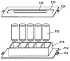
- FIG. 2A is an exploded perspective view of the battery module according to Embodiment 1 of the present invention
- FIG. 2B is a perspective view of the battery module according to Embodiment 1 of the present invention.
- the battery is shown in a transparent state to help understanding.
- the battery module 100 is assembled between the first casing 110 and the second casing 120 made of an insulating resin material such as polycarbonate resin, and between the first casing 110 and the second casing 120. It is composed of a plurality of batteries 130.
- the first casing 110 includes a first partition member 115 at a position facing the exhaust hole of the battery 130.
- the battery module 100 is configured by a battery arrangement in which a plurality of batteries 130 are connected in parallel, for example.
- a first connection terminal (not shown) and a second connection terminal 122 for electrically connecting a plurality of batteries 130 are connected to the first casing 110 and the second casing 120 by, for example, spot welding.
- the first connecting part 114 and the second connecting part 124 are provided in the first casing 110 and the second casing 120.
- the 1st connection part 114 and the 2nd connection part 124 are electrically connected with the 1st connection terminal and the 2nd connection terminal 122, and may be used as an electrical connection part at the time of connecting with another battery module.
- the exhaust hole side of the plurality of batteries 130 is housed in the first partition member 115 of the first casing 110, and the first connection terminal (not shown) is connected to the positive electrode cap of the battery 130.
- the battery module 100 is configured by connecting the second connection terminal 122 of the second casing 120 and the battery case (specifically, the minus side) of the battery 130.
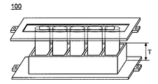
- the height (depth) T of the first partition member 115 may be at least the height at which the exhaust hole portion of the battery 130 can be accommodated and not more than the height of the battery 130. For example, in the case of a battery having an outer diameter of 18 mm and a height of 65 mm, 2 mm ⁇ T ⁇ 65 mm.
- the first partition member can prevent the high temperature gas from directly hitting the surrounding battery. As a result, it is possible to effectively prevent the surrounding batteries from being chain-heated. Further, the higher the height of the first partition member, the more radiant heat that is radiated from the side surface of the battery case of the battery can be surely shielded, so that the influence on the surrounding batteries can be further suppressed.
- the first casing, the second casing, and the first partition member have been described as an example made of a heat-resistant member such as a polycarbonate resin having a heat resistance of about 200 ° C., but is not limited thereto.
- a heat-resistant member is used only for the first housing including the first partition member, and a resin member such as polypropylene (PP) or polyethylene (PE) having a low heat resistance of, for example, about 100 ° C. is used for the second housing. May be. Thereby, production cost can be reduced.
- the heat-resistant member for example, polyphenylene sulfide (PPS) resin, polycarbonate (PC) resin, polyether ether ketone (PEEK) resin, phenol resin, unilate, glass epoxy resin, ceramic or foamed resin may be used.
- fillers such as carbon fiber and glass fiber
- a metal material such as aluminum (Al), copper (Cu), iron (Fe), or nickel (Ni) coated with an insulating resin may be used.
- the metal material may be a plate shape or a mesh (mesh shape). If it is a mesh shape, high mechanical strength and weight reduction of a housing can be achieved.
- the insulating resin a heat-resistant member is not necessarily used, and an insulating resin that is inexpensive and easy to form may be used.
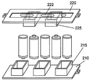
- FIG. 3A is an exploded perspective view of another example of the battery module according to Embodiment 1 of the present invention
- FIG. 3B is a perspective view of another example of the battery module according to Embodiment 1 of the present invention.
- the battery is shown in a transparent state.
- the battery module 200 has a configuration in which the exhaust holes of the plurality of batteries 130 are housed in the first casing 210 and the second casing 220 in different positions.
- the battery module 100 is different from the battery module 100 of the above embodiment in that the first partition member 215 and the second partition member 225 are provided in the first casing 210 and the second casing 220 at positions facing the exhaust holes of the battery. That is, the battery module 200 is an example of a configuration when a plurality of batteries are connected in series. Therefore, adjacent batteries are connected by a first connection terminal (not shown) and a second connection terminal 222.
- the first casing 210, the second casing 220, the first partition member 215, and the second partition member 225 are formed of the same heat-resistant members as the first casing 110 and the first partition member 115 of the battery module 100. Since other components are the same as those of the battery module 100, description thereof is omitted.
- the first partition member and the second partition member cause It is possible to prevent direct hitting of gas. As a result, it is possible to effectively prevent the surrounding batteries from being chain-heated.
- Embodiment 2 the battery module according to Embodiment 2 of the present invention will be described in detail with reference to FIGS. 4A and 4B.
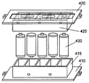
- FIG. 4A is an exploded perspective view of the battery module according to Embodiment 2 of the present invention
- FIG. 4B is a perspective view of the battery module according to Embodiment 2 of the present invention.
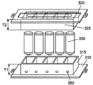
- the battery module 300 is provided with a first partition member 315 in the first casing 310 and a second partition member 325 in the second casing 320 corresponding to all of the plurality of batteries 330 to be housed.
- the first embodiment is different from the first embodiment in that a vent hole 350 is provided on the outer peripheral wall surface of either the first partition member 315 or the second partition member 325 in the vicinity of the position of the exhaust hole of the battery 330.
- the total of the battery 330 is accommodated by setting the sum of the height T1 (depth) of the first partition member 315 and the height T2 (depth) of the second partition member 325 to at least the height of the battery 330.
- FIGS. 4A and 4B show an example in which a plurality of batteries 330 are connected in parallel, and the exhaust hole side of the battery 330 is disposed to face the first partition member 315 of the first casing 310. Therefore, the first casing 310 and the first partition member 315 need to use heat resistant members such as polyphenylene sulfide resin having heat resistance of about 200 ° C., for example. On the other hand, for the second casing and the second partition member 325, a member having low heat resistance of about 100 ° C. such as polyethylene resin may be used.
- the battery becomes hot due to an abnormal situation, and even if high temperature gas is ejected from the exhaust hole, the battery is discharged from the vent hole, and the surrounding battery is separated by the first partition member and the second partition member. It is possible to prevent direct contact with high-temperature gas. Further, since the battery is completely accommodated by the first partition member and the second partition member, the radiant heat radiated from the side surface of the battery case of the battery can be reliably shielded, so that the influence on the surrounding batteries can be further suppressed.
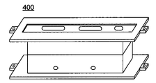
- a battery module in which a plurality of batteries are connected in parallel has been described as an example.
- the present invention is not limited to this.
- a plurality of batteries 430 may be connected in series to constitute the battery module 400 shown in FIG. 5B.
- a heat-resistant member such as a polycarbonate resin having a heat resistance of about 200 ° C., for example. Since other components are the same as those of the battery module 300, description thereof is omitted.
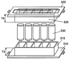
- FIG. 6A is an exploded perspective view of the battery module according to Embodiment 3 of the present invention
- FIG. 6B is a perspective view of the battery module according to Embodiment 3 of the present invention.
- the sum of the height T3 (depth) of the first partition member 515 and the height T4 (depth) of the second partition member 525 is made smaller than the height of the battery, and the difference ( It differs from the battery module of Embodiment 2 in that the gap portion is a vent hole.
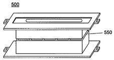
- the battery module 500 is provided with a first partition member 515 on the first casing 510 and a second partition member 525 on the second casing 520 corresponding to all of the plurality of batteries 530 to be housed.
- the sum of the height T3 (depth) of the first partition wall member 515 and the height T4 (depth) of the second partition wall member 525 is at least equal to or less than the height of the battery 530, and the difference between them is the air hole 550. It is used as
- the height of the first partition member or the second partition member facing the exhaust hole of the battery is at least higher than the height at which the exhaust hole of the battery is accommodated.
- the first partition member and the second partition member can prevent the high-temperature gas from directly hitting the surrounding battery. As a result, a battery module with excellent reliability and safety can be realized.
- the gap portion that is the vent hole 550 is described as being formed all around the battery.
- the present invention is not limited to this.
- the sum of the wall surfaces of the first partition member or the second partition member between adjacent batteries may be set to the height of the battery.
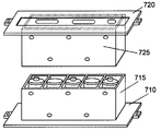
- Embodiment 4 the battery module according to Embodiment 4 of the present invention will be described in detail with reference to FIGS. 7A and 7B.
- FIG. 7A is an exploded perspective view of the battery module according to Embodiment 4 of the present invention
- FIG. 7B is a perspective view of the battery module according to Embodiment 4 of the present invention.
- the battery module 600 includes a second partition member 625 of the second casing 620 provided corresponding to the first partition member 615 of the first casing 610 that individually accommodates the plurality of batteries 630. ing.
- the second partition member 625 is different from the second embodiment in that the second partition member 625 has a structure that accommodates the entire first partition member 615. At this time, the sum total of the height of the 1st partition member 615 and the 2nd partition member 625 is more than the height of a battery. That is, the battery 630 is accommodated in a state where the first partition member 615 and the second partition member 625 partially overlap.
- the height (depth) of the second partition member 625 is about the height of the battery, it is preferable to provide a vent at the same position where the first partition member and the second partition member overlap.
- the gap can be used as a vent hole. It is not necessary to provide a vent hole in each partition member.
- the first partition member and the second partition member are provided with the partition walls, a battery module with further improved reliability and safety can be realized.
- a battery module 700 may be configured by connecting a plurality of batteries in series, and the same effect can be obtained.
- the first casing 710, the first partition member 715, the second casing 720, and the second partition member 725 need to be made of a heat-resistant member having excellent heat resistance.
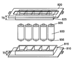
- Embodiment 5 the battery module according to Embodiment 5 of the present invention will be described in detail with reference to FIGS. 9A and 9B.
- FIG. 9A is an exploded perspective view of the battery module according to Embodiment 5 of the present invention
- FIG. 9B is a perspective view of the battery module according to Embodiment 5 of the present invention.
- FIG. 9A and FIG. 9B it is composed of a first casing 810 and a second casing 820 made of an insulating resin material such as polycarbonate resin, and a plurality of batteries 830 incorporated in those casings.
- the battery 830 has an exhaust hole on the plus side, and further includes an explosion-proof valve 835 made of, for example, a C-shaped mark on the minus side, and is configured by a battery arrangement in which a plurality of batteries 830 are connected in parallel. Yes.
- the first partition member 815 of the first casing 810 is provided at a position facing the exhaust hole of the battery 830
- the second partition member 825 of the second casing 820 is provided at a position facing the explosion-proof valve 835 of the battery 830.
- the height T5 of the first partition member 815 and the height T6 of the second partition member 825 facing the exhaust hole of the battery 830 and the explosion-proof valve 835 are at least the height at which the exhaust hole of the battery 830 and the explosion-proof valve 835 open. That is important.
- first casing 810, the second casing 820, the first partition member 815, and the second partition member 825 are formed of the same heat-resistant members as the first casing 110 and the first partition member 115 of the battery module 100.
- Other constituent elements, constituent materials, and the like are the same as those of the battery module 100, and thus description thereof is omitted.
- the high-temperature gas is supplied to the surrounding battery by the first partition member and the second partition member. Can be prevented directly. As a result, it is possible to prevent the surrounding batteries from being chain-heated and to realize a safe and reliable battery module.
- FIG. 10A is an exploded perspective view of another example of the battery module according to Embodiment 5 of the present invention
- FIG. 10B is a perspective view of another example of the battery module according to Embodiment 5 of the present invention.
- the battery module 900 is different from the battery module 800 described above in that both the positive side and the negative side of the battery 930 are caulked through a sealing plate. And at least to the position of the exhaust hole 935 provided at both ends of the battery, the first partition member 815 of the first casing 810 and the second partition member 825 of the second casing 820 are accommodated.
- the same effect as described above can be obtained for batteries having different structures.
- the present invention is not limited to this.
- the sum of the height of the first partition member and the height of the second partition member may be made equal to the height of the battery.
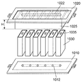
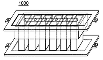
- FIG. 11A is an exploded perspective view of the battery module according to Embodiment 6 of the present invention
- FIG. 11B is a perspective view of the battery module according to Embodiment 6 of the present invention.
- the battery module 1000 is different from the first embodiment in that a rectangular battery 1030 is used as a battery to be stored.
- the battery 1030 has a vent mechanism 1035 in the vicinity of the center thereof.
- the vent mechanism 1035 side of the plurality of batteries 1030 is housed in the second partition member 1025 of the second housing 1020 and connected in parallel with the second connection terminal 1022, and the first housing 1010
- the battery module 1000 is configured by connecting the first connection terminal 1012 and the battery case of the battery 1030.
- the height (depth) H of the second partition wall member 1025 may be at least the height that can accommodate the vent mechanism 1035 of the battery 1030 and not more than the height of the battery 1030. For example, in the case of a battery having a width of 34 mm and a height of 50 mm, 2 mm ⁇ H ⁇ 52 mm.
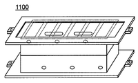
- FIG. 12A is an exploded perspective view of another example of the battery module according to Embodiment 6 of the present invention
- FIG. 12B is a perspective view of another example of the battery module according to Embodiment 6 of the present invention.
- the battery module 1100 has a configuration in which a bent mechanism 1135 is connected in series with a rectangular battery 1130 provided at a position away from the central portion of the sealing plate 1132.
- a first partition member 1115 and a second partition member 1125 are provided on the first casing 1110 and the second casing 1120 at positions facing the vent mechanism 1135 of the battery 1130.
- the sum of the height T7 of the first partition member 1115 facing the vent mechanism 1135 of the battery 1130 and the height T8 of the second partition member 1125 is equal to or higher than the height of the battery 1130.
- a vent hole 1150 is provided in the vicinity of the position of the vent mechanism 1135 at least on the outer surface of the first partition member 1115 or the second partition member 1125 that is not adjacent to the battery 1130.
- the same effect as described above can be obtained for a battery having a vent mechanism at a different position. Therefore, a safe and highly reliable battery module can be realized regardless of the arrangement of the batteries.
- the present invention is not limited thereto.
- the sum of the height of the first partition member and the height of the second partition member may be made lower than the height of the battery. In this case, there is no need to provide a vent hole in the first partition member or the second partition member.
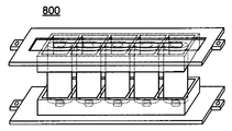
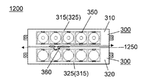
- Embodiment 7 the battery module according to Embodiment 7 of the present invention will be described in detail with reference to FIGS. 13A and 13B.
- FIG. 13A is a plan view of the battery module according to Embodiment 7 of the present invention as viewed from the direction in which the battery is stored, and is a diagram illustrating a state in which the battery modules are connected in two columns.
- FIG. 13B is a plan view of the battery module according to Embodiment 7 of the present invention as viewed from the direction in which the battery is stored, and illustrates a state in which the battery modules are connected in parallel in two rows and in two columns.
- the battery, each partition member, and the like are shown in a transparent state for easy understanding.
- the battery module 1200 is configured by stacking the battery modules 300 described in the second embodiment in two stages in cascade through the outer shapes of the first casing 310 and the second casing 320. Yes. And the exhaust flow path 1250 formed in the space of the 1st housing 310 and the 2nd housing 320 of the battery module 300, the 1st partition member 315, and the 2nd partition member 325 is formed.
- the battery module 300 is provided with the ventilation hole 350, it is preferable to provide the ventilation hole between the battery modules laminated
- the battery becomes hot due to an abnormal situation, and the high temperature gas 360 ejected from the vent hole 350 can be discharged to the outside through the exhaust passage 1250 as indicated by the arrow in the drawing.
- the high-temperature gas 360 it is possible to prevent the high-temperature gas 360 from directly hitting the batteries in the battery module and the surrounding batteries facing each other between the battery modules.
- the battery module 1200 shown in FIG. 13A may be connected in parallel to form the battery module 1300.
- a battery module satisfying the required voltage and capacity can be configured by arbitrarily connecting battery modules in tandem or in parallel.
- the battery module 300 of the second embodiment has been described as an example.
- the present invention is not limited to this, and the battery module may be configured by arbitrarily combining the battery modules of the above-described embodiments.
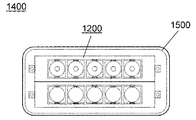
- FIG. 14 is a perspective plan view of the battery pack according to Embodiment 8 of the present invention.
- the battery pack 1400 has a configuration in which, for example, the battery module 1200 according to the seventh embodiment is housed in an exterior casing 1500.
- the exterior casing 1500 has at least an external connection terminal (not shown) for connecting to an external device or device, and the external connection terminal is connected to the connection terminal of the battery module 1200.
- a battery pack having excellent reliability and safety and high versatility can be realized.
- the first casing and the second casing have been described by taking the outer shape of the first partition member and the outer shape of the second partition member as an example.
- the present invention is not limited to this. Absent.
- the outer shape of the first housing and the first partition member and the outer shape of the second housing and the second partition member may be equal. Thereby, a smaller and lighter battery module can be realized.
- the configuration can be applied to each other.
- the present invention is useful in technical fields such as battery modules and battery packs that require high reliability and safety as power sources for automobiles, bicycles, electric tools, and the like.
Abstract
Description
1a 正極集電体
1b 正極層
2 負極
3 セパレータ
4 電極群
5 電池ケース
6,1132 封口板
7 ガスケット
8 正極リード
9 負極リード
10a,10b 絶縁板
11 負極集電体
15 負極層
16 正極キャップ
17,935 排気孔
18 電流遮断部材
19,1035,1135 ベント機構
100,200,300,400,500,600,700,800,900,1000,1100,1200,1300 電池モジュール
110,210,310,410,510,610,710,810,1010,1110 第1筺体
114 第1連結部
115,215,315,415,515,615,715,815,1115 第1隔壁部材
120,220,320,420,520,620,720,820,1020,1120 第2筺体
122,222,1022 第2接続端子
124 第2連結部
130,330,430,530,630,830,930,1030,1130 電池
225,325,425,525,625,725,825,1025,1125 第2隔壁部材
350,550,1150 通気孔
360 ガス
835 防爆弁
1012 第1接続端子
1250 排気流路
1400 電池パック
1500 外装筺体
図1は、本発明の実施の形態1における電池モジュールに収納される電池の横断面図である。
以下、本発明の実施の形態2における電池モジュールについて、図4Aと図4Bを用いて詳細に説明する。
以下、本発明の実施の形態3における電池モジュールについて、図6Aと図6Bを用いて詳細に説明する。
以下、本発明の実施の形態4における電池モジュールについて、図7Aと図7Bを用いて詳細に説明する。
以下、本発明の実施の形態5における電池モジュールについて、図9Aと図9Bを用いて詳細に説明する。
以下、本発明の実施の形態6における電池モジュールについて、図11Aと図11Bを用いて詳細に説明する。
以下、本発明の実施の形態7における電池モジュールについて、図13Aと図13Bを用いて詳細に説明する。
以下、本発明の実施の形態8における電池パックについて、図14を用いて詳細に説明する。
Claims (10)
- 第1筺体と、
第2筺体と、
前記第1筺体と前記第2筺体との間に収納される排気孔を有する複数の電池を備え、
前記第1筺体および前記第2筺体の少なくとも一方で前記電池の前記排気孔と対向する位置に、前記電池を個別に収納する第1隔壁部材を設けたことを特徴とする電池モジュール。 - 前記第1隔壁部材の高さが、前記電池の排気孔を収納する高さ以上で、前記電池の高さ以下であることを特徴とする請求項1に記載の電池モジュール。
- 前記第1筺体および前記第2筺体の少なくとも一方で前記電池の前記排気孔の反対側と対向する位置に、前記第1隔壁部材に対応して、前記電池を個別に収納する第2隔壁部材を設けたことを特徴とする請求項1に記載の電池モジュール。
- 前記第1筺体および前記第2筺体の少なくとも一方で前記電池の前記排気孔の反対側と対向する位置に、前記第1隔壁部材に対応して、前記第1隔壁部材を収納する第2隔壁部材を設けたことを特徴とする請求項1に記載の電池モジュール。
- 前記第1隔壁部材および前記第2隔壁部材の少なくとも一方に、通気孔を設けたことを特徴とする請求項3または請求項4に記載の電池モジュール。
- 前記第1隔壁部材と前記第2隔壁部材の高さの和が、前記電池の高さ以下で、前記電池の高さと、前記第1隔壁部材と前記第2隔壁部材の高さの和との差を通気孔とすることを特徴とする請求項3に記載の電池モジュール。
- 前記第1筺体および前記第2筺体の少なくとも一方は、耐熱部材からなることを特徴とする請求項1に記載の電池モジュール。
- 前記耐熱部材が、金属材料を絶縁性樹脂で被覆した構成からなることを特徴とする請求項7に記載の電池モジュール。
- 請求項1に記載の前記電池モジュールを、縦列または並列に接続したことを特徴とする電池モジュール。
- 請求項1に記載の前記電池モジュールを、外装筺体に収納したことを特徴とする電池パック。
Priority Applications (4)
| Application Number | Priority Date | Filing Date | Title |
|---|---|---|---|
| CN200980100425A CN101803063A (zh) | 2008-03-04 | 2009-01-21 | 电池组件及使用该电池组件的电池组 |
| KR1020107004661A KR101160400B1 (ko) | 2008-03-04 | 2009-01-21 | 전지 모듈 및 그들을 이용한 전지 팩 |
| US12/747,833 US20100266880A1 (en) | 2008-03-04 | 2009-01-21 | Battery module and battery pack using said battery module |
| EP09717152A EP2202824A4 (en) | 2008-03-04 | 2009-01-21 | BATTERY MODULE AND BATTERY PACK USING THE BATTERY MODULE |
Applications Claiming Priority (2)
| Application Number | Priority Date | Filing Date | Title |
|---|---|---|---|
| JP2008-052998 | 2008-03-04 | ||
| JP2008052998A JP2009211907A (ja) | 2008-03-04 | 2008-03-04 | 電池モジュールおよびそれらを用いた電池パック |
Publications (1)
| Publication Number | Publication Date |
|---|---|
| WO2009110167A1 true WO2009110167A1 (ja) | 2009-09-11 |
Family
ID=41055736
Family Applications (1)
| Application Number | Title | Priority Date | Filing Date |
|---|---|---|---|
| PCT/JP2009/000194 WO2009110167A1 (ja) | 2008-03-04 | 2009-01-21 | 電池モジュールおよびそれらを用いた電池パック |
Country Status (6)
| Country | Link |
|---|---|
| US (1) | US20100266880A1 (ja) |
| EP (1) | EP2202824A4 (ja) |
| JP (1) | JP2009211907A (ja) |
| KR (1) | KR101160400B1 (ja) |
| CN (1) | CN101803063A (ja) |
| WO (1) | WO2009110167A1 (ja) |
Cited By (4)
| Publication number | Priority date | Publication date | Assignee | Title |
|---|---|---|---|---|
| WO2012014418A1 (ja) * | 2010-07-30 | 2012-02-02 | パナソニック株式会社 | 電池モジュール |
| US20120164490A1 (en) * | 2009-09-18 | 2012-06-28 | Toshiki Itoi | Battery module |
| WO2013021573A1 (ja) * | 2011-08-10 | 2013-02-14 | パナソニック株式会社 | 電池ブロック及び該電池ブロックを有する電池モジュール |
| US20130095356A1 (en) * | 2010-08-06 | 2013-04-18 | Panasonic Corporation | Cell module |
Families Citing this family (29)
| Publication number | Priority date | Publication date | Assignee | Title |
|---|---|---|---|---|
| JP2013214354A (ja) * | 2010-07-30 | 2013-10-17 | Panasonic Corp | 電池モジュール |
| KR101283347B1 (ko) * | 2010-09-07 | 2013-07-10 | 주식회사 엘지화학 | 고출력 대용량의 전지팩 |
| CN101944638B (zh) * | 2010-09-08 | 2013-06-12 | 奇瑞汽车股份有限公司 | 一种电动汽车用锂离子电池组的制造方法 |
| US20120094541A1 (en) * | 2010-10-13 | 2012-04-19 | Braille Battery, Inc. | Direct-Connect High-Rate Battery Connector |
| KR101326196B1 (ko) * | 2010-11-22 | 2013-11-07 | 주식회사 엘지화학 | 콤팩트한 구조의 전지팩 |
| US9472791B2 (en) * | 2011-08-11 | 2016-10-18 | Johnson Controls Technology Company | Battery system, housing and vehicle including battery system |
| JP6103856B2 (ja) * | 2012-08-20 | 2017-03-29 | ホーチキ株式会社 | 電気自動車向け消火システム |
| DE102012223518A1 (de) * | 2012-12-18 | 2014-06-18 | Robert Bosch Gmbh | Energiespeicher mit Isolationselement |
| US10044077B2 (en) * | 2013-02-26 | 2018-08-07 | The Boeing Company | Rechargeable battery including battery cell separators |
| CN104377335B (zh) * | 2013-08-12 | 2017-07-07 | 深圳市沃特玛电池有限公司 | 大容量锂离子电池包 |
| JP6245038B2 (ja) | 2014-03-31 | 2017-12-13 | 株式会社Gsユアサ | 蓄電装置 |
| DE102014206646A1 (de) | 2014-04-07 | 2015-10-08 | Robert Bosch Gmbh | Energiespeichereinheit, insbesondere Batteriemodul, und Energiespeichersystem mit einer Mehrzahl von Energiespeichereinheiten |
| DE102014206903A1 (de) | 2014-04-10 | 2015-10-15 | Robert Bosch Gmbh | Energiespeichereinheit umfassend eine Mehrzahl von Energiespeichersubeinheiten sowie Energiespeichersystem mit einer Mehrzahl von Energiespeichereinheiten |
| DE102014207403A1 (de) | 2014-04-17 | 2015-10-22 | Robert Bosch Gmbh | Batterieeinheit mit einer Aufnahmeeinrichtung und einer Mehrzahl von elektrochemischen Zellen sowie Batteriemodul mit einer Mehrzahl von solchen Batterieeinheiten |
| DE102014210097A1 (de) | 2014-05-27 | 2015-12-17 | Robert Bosch Gmbh | Batterieeinheit mit einer Mehrzahl von Batteriezellen sowie Batteriemodul mit einer Mehrzahl solcher Batterieeinheiten |
| CN105322113B (zh) | 2014-07-30 | 2019-09-27 | 株式会社杰士汤浅国际 | 蓄电装置 |
| EP3410512B1 (en) * | 2016-01-26 | 2022-02-16 | Sanyo Electric Co., Ltd. | Battery pack |
| TWI587560B (zh) * | 2016-08-08 | 2017-06-11 | A battery module with a high temperature gas channel structure | |
| CN107768578A (zh) * | 2016-08-16 | 2018-03-06 | 原道电子股份有限公司 | 具有高温气体通道结构的电池模块 |
| DE102016116729B4 (de) * | 2016-09-07 | 2020-12-31 | Kirchhoff Automotive Deutschland Gmbh | Batteriegehäuse für ein elektromotorisch angetriebenes Fahrzeug |
| JP6925245B2 (ja) * | 2017-12-01 | 2021-08-25 | タイガースポリマー株式会社 | 組電池の耐火断熱構造用の樹脂組成物及び組電池の耐火断熱部材 |
| KR102263763B1 (ko) | 2018-01-17 | 2021-06-09 | 주식회사 엘지에너지솔루션 | 방열 및 연쇄발화 방지 구조를 구비한 멀티 레이어 원통형 전지모듈 및 이를 포함하는 전지팩 |
| US11600879B2 (en) * | 2018-11-07 | 2023-03-07 | Sk On Co., Ltd. | Battery module |
| JP7346057B2 (ja) * | 2019-03-28 | 2023-09-19 | パナソニックエナジー株式会社 | 電池パック |
| JP7301271B2 (ja) * | 2019-03-28 | 2023-07-03 | パナソニックエナジー株式会社 | 電池パック |
| US11850956B2 (en) | 2021-05-14 | 2023-12-26 | Deere & Company | Battery arrangement of a compact electric tractor |
| KR20230046463A (ko) * | 2021-09-30 | 2023-04-06 | 에스케이온 주식회사 | 배터리 모듈 또는 이를 포함하는 배터리 팩 |
| KR20230055046A (ko) | 2021-10-18 | 2023-04-25 | 주식회사 엘지에너지솔루션 | 화재 방지용 배터리모듈 및 이의 제작방법 |
| KR20240043384A (ko) | 2022-09-27 | 2024-04-03 | 주식회사 엘지에너지솔루션 | 연쇄 발화 방지용 배터리모듈 및 이의 제조 방법 |
Citations (3)
| Publication number | Priority date | Publication date | Assignee | Title |
|---|---|---|---|---|
| JP2002015716A (ja) * | 2000-06-30 | 2002-01-18 | Sanyo Electric Co Ltd | バッテリーパック |
| JP2003346749A (ja) * | 2002-05-30 | 2003-12-05 | Japan Storage Battery Co Ltd | 組電池及びこの組電池用の枠体 |
| JP2008218210A (ja) * | 2007-03-05 | 2008-09-18 | Lenovo Singapore Pte Ltd | 電池パックおよび携帯式電子機器 |
Family Cites Families (6)
| Publication number | Priority date | Publication date | Assignee | Title |
|---|---|---|---|---|
| JP3741359B2 (ja) * | 1999-11-11 | 2006-02-01 | 株式会社マキタ | バッテリーパック |
| JP3848565B2 (ja) * | 2001-11-27 | 2006-11-22 | 松下電器産業株式会社 | 電池間接続構造および電池モジュール並びに電池パック |
| US8632898B2 (en) * | 2003-10-28 | 2014-01-21 | Johnson Controls Technology Company | Battery system including batteries that have a plurality of positive terminals and a plurality of negative terminals |
| EP1878085B1 (en) * | 2005-03-14 | 2016-04-20 | Johnson Controls Technology Company | Lithium battery system |
| JP2007059170A (ja) * | 2005-08-24 | 2007-03-08 | Matsushita Electric Ind Co Ltd | 電池パック |
| CN101627490B (zh) * | 2006-12-14 | 2012-10-03 | 江森自控帅福得先进能源动力系统有限责任公司 | 电池模块 |
-
2008
- 2008-03-04 JP JP2008052998A patent/JP2009211907A/ja not_active Withdrawn
-
2009
- 2009-01-21 US US12/747,833 patent/US20100266880A1/en not_active Abandoned
- 2009-01-21 CN CN200980100425A patent/CN101803063A/zh active Pending
- 2009-01-21 WO PCT/JP2009/000194 patent/WO2009110167A1/ja active Application Filing
- 2009-01-21 EP EP09717152A patent/EP2202824A4/en not_active Withdrawn
- 2009-01-21 KR KR1020107004661A patent/KR101160400B1/ko not_active IP Right Cessation
Patent Citations (3)
| Publication number | Priority date | Publication date | Assignee | Title |
|---|---|---|---|---|
| JP2002015716A (ja) * | 2000-06-30 | 2002-01-18 | Sanyo Electric Co Ltd | バッテリーパック |
| JP2003346749A (ja) * | 2002-05-30 | 2003-12-05 | Japan Storage Battery Co Ltd | 組電池及びこの組電池用の枠体 |
| JP2008218210A (ja) * | 2007-03-05 | 2008-09-18 | Lenovo Singapore Pte Ltd | 電池パックおよび携帯式電子機器 |
Non-Patent Citations (1)
| Title |
|---|
| See also references of EP2202824A4 * |
Cited By (10)
| Publication number | Priority date | Publication date | Assignee | Title |
|---|---|---|---|---|
| US20120164490A1 (en) * | 2009-09-18 | 2012-06-28 | Toshiki Itoi | Battery module |
| US8956747B2 (en) | 2009-09-18 | 2015-02-17 | Panasonic Intellectual Property Management Co., Ltd. | Battery module |
| WO2012014418A1 (ja) * | 2010-07-30 | 2012-02-02 | パナソニック株式会社 | 電池モジュール |
| CN102484235A (zh) * | 2010-07-30 | 2012-05-30 | 松下电器产业株式会社 | 电池模块 |
| JP4973824B2 (ja) * | 2010-07-30 | 2012-07-11 | パナソニック株式会社 | 電池モジュール |
| US8399114B2 (en) | 2010-07-30 | 2013-03-19 | Panasonic Corporation | Battery module |
| US20130095356A1 (en) * | 2010-08-06 | 2013-04-18 | Panasonic Corporation | Cell module |
| CN103081164A (zh) * | 2010-08-06 | 2013-05-01 | 松下电器产业株式会社 | 电池模块 |
| US9231237B2 (en) * | 2010-08-06 | 2016-01-05 | Panasonic Intellectual Property Management Co., Ltd. | Cell module |
| WO2013021573A1 (ja) * | 2011-08-10 | 2013-02-14 | パナソニック株式会社 | 電池ブロック及び該電池ブロックを有する電池モジュール |
Also Published As
| Publication number | Publication date |
|---|---|
| CN101803063A (zh) | 2010-08-11 |
| JP2009211907A (ja) | 2009-09-17 |
| EP2202824A4 (en) | 2012-12-12 |
| US20100266880A1 (en) | 2010-10-21 |
| EP2202824A1 (en) | 2010-06-30 |
| KR20100070322A (ko) | 2010-06-25 |
| KR101160400B1 (ko) | 2012-06-26 |
Similar Documents
| Publication | Publication Date | Title |
|---|---|---|
| WO2009110167A1 (ja) | 電池モジュールおよびそれらを用いた電池パック | |
| JP4935802B2 (ja) | 電池モジュールとそれを用いた集合電池モジュール | |
| US8399112B2 (en) | Battery module and battery pack using the same | |
| KR101370238B1 (ko) | 전지 모듈과 이를 이용한 전지 팩 | |
| JP4900534B2 (ja) | 電池モジュールとそれを用いた電池モジュール集合体 | |
| JP5507173B2 (ja) | 電池モジュールとそれを用いた電池パック | |
| JP5338331B2 (ja) | 電池パック、それを備えた電子機器 | |
| JP4815016B2 (ja) | 電池接続部材とそれを用いた電池モジュール | |
| JP4973824B2 (ja) | 電池モジュール | |
| WO2012014398A1 (ja) | 電池モジュール及びそれを用いた電池パック | |
| KR20120049839A (ko) | 전지모듈과 이를 이용한 전지 팩 | |
| JP2009211908A (ja) | 電池およびそれを用いた電池パック | |
| JP2011070872A (ja) | 電池モジュール | |
| JP2011023260A (ja) | 二次電池 |
Legal Events
| Date | Code | Title | Description |
|---|---|---|---|
| WWE | Wipo information: entry into national phase |
Ref document number: 200980100425.7 Country of ref document: CN |
|
| 121 | Ep: the epo has been informed by wipo that ep was designated in this application |
Ref document number: 09717152 Country of ref document: EP Kind code of ref document: A1 |
|
| WWE | Wipo information: entry into national phase |
Ref document number: 2009717152 Country of ref document: EP |
|
| ENP | Entry into the national phase |
Ref document number: 20107004661 Country of ref document: KR Kind code of ref document: A |
|
| WWE | Wipo information: entry into national phase |
Ref document number: 12747833 Country of ref document: US |
|
| NENP | Non-entry into the national phase |
Ref country code: DE |