US9048024B2 - Solid electrolytic capacitor and method for producing the same - Google Patents
Solid electrolytic capacitor and method for producing the same Download PDFInfo
- Publication number
- US9048024B2 US9048024B2 US13/614,594 US201213614594A US9048024B2 US 9048024 B2 US9048024 B2 US 9048024B2 US 201213614594 A US201213614594 A US 201213614594A US 9048024 B2 US9048024 B2 US 9048024B2
- Authority
- US
- United States
- Prior art keywords
- electroconductive polymer
- polymer layer
- layer
- solid electrolytic
- electrolytic capacitor
- Prior art date
- Legal status (The legal status is an assumption and is not a legal conclusion. Google has not performed a legal analysis and makes no representation as to the accuracy of the status listed.)
- Active, expires
Links
Images


Classifications
-
- H—ELECTRICITY
- H01—ELECTRIC ELEMENTS
- H01G—CAPACITORS; CAPACITORS, RECTIFIERS, DETECTORS, SWITCHING DEVICES OR LIGHT-SENSITIVE DEVICES, OF THE ELECTROLYTIC TYPE
- H01G9/00—Electrolytic capacitors, rectifiers, detectors, switching devices, light-sensitive or temperature-sensitive devices; Processes of their manufacture
- H01G9/004—Details
- H01G9/04—Electrodes or formation of dielectric layers thereon
-
- H—ELECTRICITY
- H01—ELECTRIC ELEMENTS
- H01G—CAPACITORS; CAPACITORS, RECTIFIERS, DETECTORS, SWITCHING DEVICES OR LIGHT-SENSITIVE DEVICES, OF THE ELECTROLYTIC TYPE
- H01G9/00—Electrolytic capacitors, rectifiers, detectors, switching devices, light-sensitive or temperature-sensitive devices; Processes of their manufacture
- H01G9/004—Details
- H01G9/022—Electrolytes; Absorbents
- H01G9/025—Solid electrolytes
-
- H—ELECTRICITY
- H01—ELECTRIC ELEMENTS
- H01G—CAPACITORS; CAPACITORS, RECTIFIERS, DETECTORS, SWITCHING DEVICES OR LIGHT-SENSITIVE DEVICES, OF THE ELECTROLYTIC TYPE
- H01G11/00—Hybrid capacitors, i.e. capacitors having different positive and negative electrodes; Electric double-layer [EDL] capacitors; Processes for the manufacture thereof or of parts thereof
- H01G11/54—Electrolytes
- H01G11/56—Solid electrolytes, e.g. gels; Additives therein
-
- H—ELECTRICITY
- H01—ELECTRIC ELEMENTS
- H01G—CAPACITORS; CAPACITORS, RECTIFIERS, DETECTORS, SWITCHING DEVICES OR LIGHT-SENSITIVE DEVICES, OF THE ELECTROLYTIC TYPE
- H01G9/00—Electrolytic capacitors, rectifiers, detectors, switching devices, light-sensitive or temperature-sensitive devices; Processes of their manufacture
- H01G9/004—Details
- H01G9/022—Electrolytes; Absorbents
- H01G9/025—Solid electrolytes
- H01G9/028—Organic semiconducting electrolytes, e.g. TCNQ
-
- H—ELECTRICITY
- H01—ELECTRIC ELEMENTS
- H01G—CAPACITORS; CAPACITORS, RECTIFIERS, DETECTORS, SWITCHING DEVICES OR LIGHT-SENSITIVE DEVICES, OF THE ELECTROLYTIC TYPE
- H01G9/00—Electrolytic capacitors, rectifiers, detectors, switching devices, light-sensitive or temperature-sensitive devices; Processes of their manufacture
- H01G9/15—Solid electrolytic capacitors
Definitions
- the present invention relates to a solid electrolytic capacitor and a method producing the same.
- FIG. 3 is a schematic cross-sectional view for explaining the configuration of the conventional solid electrolytic capacitor.
- Anode body 21 is a sintered body having a lot of fine pores (porous layer) obtained by forming and sintering fine particles of a valve action metal such as tantalum or aluminum.
- Anode lead 28 which comes to be an anode part, as well as anode body 21 , includes a wire or the like of a valve action metal, and is led from the anode lead leading surface (leading surface) of anode body 21 .
- Dielectric layer 22 of an oxide film is formed on the surface of anode body 21 and on the surface inside the polar layer.
- Solid electrolyte layer 23 is formed on the surface of dielectric layer 22 .
- Insulation part 30 includes an epoxy resin and is placed at the base part of anode lead 28 so as to prevent an electrical short circuit by connecting solid electrolyte layer 23 to anode lead 28 .
- Graphite layer 24 and silver paste layer 25 as a cathode part are formed on the surface of solid electrolyte layer 23 to configure a capacitor element.
- Anode lead 28 and the cathode part of the capacitor element are electrically connected to lead frame 31 and lead frame 32 that are external electrode terminals by welding or with electroconductive adhesive 26 .
- an outer package including outer resin 29 is formed to obtain a solid electrolytic capacitor.
- the solid electrolyte layer has a function to electrically connect the dielectric layer and the cathode part and to extract an electrostatic capacity of the dielectric layer.
- the solid electrolyte layer is one of the important constituents for obtaining electrical characteristic of the solid electrolytic capacitor, and the configuration, the production method and the like are studied. In the late years, a solid electrolytic capacitor using an electroconductive polymer layer including an electroconductive polymer as the solid electrolyte layer is produced.
- chemical oxidative polymerization method is conventionally used, in which the anode body (anode body element) where the dielectric layer is formed is immersed in a solution obtained by adding a monomer, a catalyst, oxidant that is a dopant and the like to a solvent, and in which it is polymerized on the surface of the dielectric layer.
- a solvent with a low viscosity which has a good permeability and easily permeates the detail of the porous layer is generally used to obtain an electroconductive polymer layer having a characteristic that the adhesion between the dielectric layer and a layer formed as the cathode part is made good, etc.
- the method with an electroconductive polymer suspension is a method in which the anode body element is immersed and impregnated to an electroconductive polymer suspension containing an electroconductive polymer which is preliminary polymerized and to which a dopant is added, and it is pulled up, and it is then dried by heating to form an electroconductive polymer layer.
- the electroconductive polymer layer obtained by this method has characteristics that the density is high and the heat resistance is good in comparison with the electroconductive polymer layer obtained by chemical oxidative polymerization method or the like, and that the electroconductive polymer layer can be quickly formed.
- the electroconductive polymer suspension used in this method and the production method is disclosed in claims 2 and 3, and paragraphs 0014 to 0028 of JP 11-121281 A.
- the electroconductive polymer layer obtained by chemical oxidative polymerization method easily permeates the detail of the porous layer because a solution with a low viscosity is used, the electroconductive polymer layer formed has a low density due to the solution character. Therefore, there is a concern that the electroconductive polymer layer is compressed by the mold forming of the outer resin, and that the dielectric layer is connected to the graphite layer, these result in occurring an electrical short circuit or increasing LC. Also, there is a concern that a gas (oxygen) easily permeates it because of the low density, and that the increase of ESR occurs by the oxidation inside the anode body.
- oxygen oxygen
- an electroconductive polymer layer by electroconductive polymer suspension method by which an electroconductive polymer layer with a high density is obtained.
- an electroconductive polymer layer with a desired thickness can uniformly be formed on the surface of the anode body element, high reliability against the oxygen permeation and the pressure in mold forming can be realized. Therefore, a solid electrolytic capacitor obtained by forming an electroconductive polymer layer by using an electroconductive polymer suspension on the surface of the electroconductive polymer layer by chemical oxidative polymerization method is studied.
- the electroconductive polymer layer with a high density is formed by using electroconductive polymer suspension method on the whole surface of the anode body element having the electroconductive polymer layer with a low density
- a residual air or solvent inside the pore of the anode body element may be trapped. If the heating such as drying is carried out in this situation, there is a problem that the air or solvent may be expand to generate small delamination at the interface of the electroconductive polymer layer and the dielectric layer, and that the product yield is lowered by the increase of ESR or the like.
- the object of the present invention is, by solving the above-mentioned problem, to provide a solid electrolytic capacitor and a method for producing the same, in which the increase of ESR is suppressed, in which high reliability is realized, and further in which the electrical short circuit or the like is suppressed and in which the product yield is improved.
- a solid electrolytic capacitor and a method for producing the same are found, in which a second electroconductive polymer layer covers a bottom surface and side surfaces of an anode body element where a first electroconductive polymer layer is formed with opening at least a part of a leading surface of the first electroconductive polymer layer, by using an electroconductive polymer suspension with a high viscosity by electroconductive polymer suspension method, and in which high reliability is realized, and further in which the electrical short circuit or the like is suppressed and in which the product yield is improved.
- the solid electrolytic capacitor of the present invention includes:
- a capacitor element which is electrically connected to an external electrode terminal, including
- the solid electrolytic capacitor of the present invention may include the first electroconductive polymer layer formed by chemical oxidative polymerization method or by electroconductive polymer suspension method, and the second electroconductive polymer layer formed by electroconductive polymer suspension method by which an electroconductive polymer layer with a higher density than that of the first electroconductive polymer layer can be obtained.
- the solid electrolytic capacitor of the present invention may include an antioxidant layer between the second electroconductive polymer layer and the graphite layer and on at least a part of the leading surface on which the first electroconductive polymer layer is formed.
- the method for producing a solid electrolytic capacitor of the present invention includes:
- a dielectric layer on a surface of an anode body including a valve action metal containing a polar layer which has a leading surface for leading an anode lead, a bottom surface opposed to the leading surface, and side surfaces next to the leading surface and the bottom surface;
- anode lead and the cathode part electrically connecting the anode lead and the cathode part to an external electrode terminal, and forming an outer package with an insulating material.
- the first electroconductive polymer layer may be formed by chemical oxidative polymerization method or by electroconductive polymer suspension method
- the second electroconductive polymer layer may be formed by using an electroconductive polymer suspension with a higher viscosity than that of a solution used for forming the first electroconductive polymer layer.
- the method for producing a solid electrolytic capacitor of the present invention may include forming an antioxidant layer by immersion or application of an antioxidant containing solution on the leading surface on which the first electroconductive polymer layer is formed and on a surface of the second electroconductive polymer layer and by drying.
- the viscosity of the electroconductive polymer suspension with a higher viscosity is preferably 100 mPa ⁇ S or higher and 500 mPa ⁇ S or lower.
- the first electroconductive polymer layer is formed on the surface of the dielectric layer by chemical oxidative polymerization method or by electroconductive polymer suspension method, using an electroconductive polymer suspension with a low viscosity, and further the second electroconductive polymer layer covers the bottom surface and the side surfaces of the first electroconductive polymer layer formed with opening at least a part of the leading surface of the first electroconductive polymer layer, by using an electroconductive polymer suspension with a high viscosity.
- the solid electrolytic capacitor and the method producing the same can be provided, in which the increase of ESR is suppressed by preventing oxygen permeation from outside, in which it becomes easy to release residual air or the like at the time of heating, in which high reliability is realized, and further in which the electrical short circuit or the like is suppressed and in which the product yield is improved.
- FIG. 1 is a schematic cross-sectional view for explaining the configuration of the solid electrolytic capacitor of Embodiment 1 of the present invention.
- FIG. 2 is a schematic cross-sectional view for explaining the configuration of the solid electrolytic capacitor of Embodiment 2 of the present invention.
- FIG. 3 is a schematic cross-sectional view for explaining the configuration of the conventional solid electrolytic capacitor.
- FIG. 1 is a schematic cross-sectional view for explaining the configuration of the solid electrolytic capacitor of Embodiment 1 of the present invention.
- the solid electrolytic capacitor of the present invention has anode body 1 including a sintered body of a valve action metal containing a polar layer, and it has a leading surface for leading anode lead 8 .
- Dielectric layer 2 is formed on the surface of anode body 1 containing the polar layer.
- Anode body 1 is formed with a sintered body including a valve action metal fine particle, a valve action metal which is subjected to a surface area enlargement treatment by etching to be polar layer, or the like.
- the valve action metal is appropriately selected from tantalum, aluminum, titanium, niobium, zirconium, or an alloy of these, or the like.
- Dielectric layer 2 is a film by electrolytic oxidation of the surface of the valve action metal and is formed on the leading surface, side surfaces and bottom surface of anode body 1 , and on the surface inside the polar layer.
- the thickness of dielectric layer 2 can be appropriately adjusted by the voltage of the electrolytic oxidation.
- Insulation part 11 is formed at the base part of anode lead 28 by applying an epoxy resin or the like.
- first electroconductive polymer layer 3 is formed on the surface of dielectric layer 2 .
- First electroconductive polymer layer 3 is formed by either chemical oxidative polymerization method or electroconductive polymer suspension method, and it is formed so that it covers the surface of dielectric layer 2 .
- first electroconductive polymer layer 3 shows a high conductivity, it contains, for example, a polymer of a monomer containing at least one or more selected from pyrrole, thiophene, aniline and derivatives thereof, and, in particular, it preferably contains pyrrole, 3,4-ethylenedioxy thiophene or derivatives thereof.
- a sulfone acid compound is preferably contained as a dopant because it develops a high conductivity.
- first electroconductive polymer layer 3 is formed by electroconductive polymer suspension method
- electroconductive polymer suspension method in order to make it easy to permeate the detail of the porous layer, it is desirable to use an electroconductive polymer suspension with a low viscosity of 1 mPa ⁇ S or higher and 90 mPa ⁇ S or lower.
- second electroconductive polymer layer 10 is formed on the surface of first electroconductive polymer layer 3 .
- Second electroconductive polymer layer 10 is formed by electroconductive polymer suspension method, and covers the bottom surface and side surfaces of the anode body element where first electroconductive polymer layer 3 is formed with opening at least a part of the leading surface. In other words, the leading surface is not covered or the area other than the circumference of the base part which leads anode lead 8 is covered. This makes it easy to release a residual air or the like at the time of heating. Therefore, the solid electrolytic capacitor and the method producing the same can be provided, in which high reliability is realized, and further in which the electrical short circuit or the like is suppressed and in which the product yield is improved.
- an electroconductive polymer suspension with a high viscosity of 100 mPa ⁇ S or higher and 500 mPa ⁇ S or lower is preferably used for forming second electroconductive polymer layer 10 .
- the electroconductive polymer suspension used in the present invention is mainly composed of a polymer containing at least one or more selected from pyrrole, thiophene, aniline and derivatives thereof and of a solvent containing a dopant.
- the polymer preferably contains pyrrole, 3,4-ethylenedioxy thiophene or derivatives thereof because it shows high electroconductivity.
- the dopant is preferably, for example, a sulfone acid compound such as naphthalenesulfonic acid, benzenesulfonic acid, styrenesulfonic acid and derivatives thereof because it shows high electroconductivity.
- a sulfone acid compound such as naphthalenesulfonic acid, benzenesulfonic acid, styrenesulfonic acid and derivatives thereof because it shows high electroconductivity.
- the solvent may be water only and may be a mixed solvent containing an organic solvent which is soluble to water.
- the organic solvent is preferably a polar solvent such as dimethylformamide, dimethylacetamide, dimethylsulfoxide, ethyleneglycol, glycerin and sorbitol. This organic solvent is preferably added in an appropriate amount because it promotes the dissolution of the polymer in no small part and improves the film forming property.
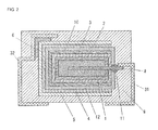
- FIG. 2 is a schematic cross-sectional view for explaining the configuration of the solid electrolytic capacitor of Embodiment 2 of the present invention.
- antioxidant layer 12 may also be formed to the leading surface which leads anode lead 8 by immersing or applying an antioxidant containing solution to the leading surface and by drying after second electroconductive polymer layer 10 is formed.
- the configuration of anode body 1 , dielectric layer 2 , first electroconductive polymer layer 3 , second electroconductive polymer layer 10 and insulation part 11 is the same as that of Embodiment 1, and thereby the explanation is omitted.
- an antioxidant which is generally used for plastic can be used, but it preferably contains at least one compound selected from the group consisting of phenolic compounds, benzophenone compounds, salicylic acid compounds and benzotriazole compounds because of the high antioxidant property.
- a pressed body in which a tantalum wire with a diameter of 0.4 mm as an anode lead was embedded in a cuboid using a tantalum powder (approximately 30,000 CV/g) with a length of 3.5 mm, a width of 3.0 mm and a height of 1.5 mm, was sintered at approximately 1,500° C. to produce an anode body having a polar layer which led the anode lead.
- Electrolytic oxidation was carried out by applying a voltage of 30 V to this anode lead in a phosphoric acid aqueous solution to form a dielectric layer.
- the anode body coated with the dielectric layer was immersed in an aqueous solution containing ammonium peroxodisulfate and 1,3,6-naphthalene trisulfonic acid as an oxidant and was dried at room temperature. After that, it was immersed in 3,4-ethylenedioxy thiophene and was further kept at room temperature to polymerize 3,4-ethylenedioxy thiophene. A series of these polymerization operations were repeated 4 times to form a first electroconductive polymer layer including an electroconductive poly-3,4-ethylenedioxy thiophene by chemical oxidative polymerization method. The thickness of the first electroconductive polymer layer was set to be 12 ⁇ m. The first electroconductive polymer layer was compressed after carrying out a mold forming, and the thickness became approximately 1 ⁇ 3.
- anode body element where the first electroconductive polymer layer was formed was washed with ethanol and was dried. After that, the bottom surface and the side surfaces of the anode body element was immersed in an electroconductive polymer suspension in which the leading surface was controlled not to be immersed in the electroconductive polymer suspension, and it was pulled up. This operation was carried out once.
- an electroconductive polymer suspension an aqueous solution obtained by mixing a poly-3,4-ethylenedioxy thiophene and polystyrene sulfonic acid in a concentration of 4% by mass with a viscosity of approximately 200 mPa ⁇ S (hereinafter, electroconductive polymer suspension A) was used. Then, it was dried at 125° C. for 1 hour to obtain a finished second electroconductive polymer layer by electroconductive polymer suspension method. The thickness of the second electroconductive polymer layer was set to be 15 ⁇ m.
- a graphite layer and a silver paste layer were formed using electroconductive pastes such as a graphite paste and a silver paste. Then, lead frames were connected respectively to the silver paste layer and the anode lead, and an outer package was formed around the whole with an outer resin by forming to obtain a solid electrolytic capacitor.
- Example 2 electroconductive polymer suspension method was also used for forming a first electroconductive polymer layer.
- the anode body element was immersed in an electroconductive polymer suspension until the solution reached the insulation part and was dried at 125° C. for 20 minutes. The operations were repeated 3 times to form a first electroconductive polymer layer.
- the thickness of the first electroconductive polymer layer was set to be 5 ⁇ m.
- Example 2 as an electroconductive polymer suspension, an aqueous solution obtained by mixing a poly-3,4-ethylenedioxy thiophene and polystyrene sulfonic acid in a concentration of 2% by mass with a viscosity of approximately 30 mPa ⁇ S was used. The following processes were the same as those in Example 1.
- Example 3 of the present invention is concretely explained.
- 3,4-ethylenedioxy thiophene was used as a monomer and an electroconductive polymer layer was formed only by chemical oxidative polymerization method. That is, the anode body element was immersed in an aqueous solution containing ammonium peroxodisulfate and 1,3,6-naphthalene trisulfonic acid as an oxidant and was then dried at room temperature. After that, it was immersed in a liquid containing 3,4-ethylenedioxy thiophene and was further kept at room temperature to polymerize 3,4-ethylenedioxy thiophene. These polymerization operations were repeated 10 times to form an electroconductive polymer layer including an electroconductive poly-3,4-ethylenedioxy thiophene.
- the operations except for the formation of the electroconductive polymer layer were the same as those in Example 1.
- the thickness of the electroconductive polymer layer was set to be 30 ⁇ m.
- the electroconductive polymer layer of Comparative Example 1 was compressed after carrying out a mold forming, and the thickness became approximately 1 ⁇ 3.
- a first electroconductive polymer layer was formed in the same manner as in Example 1. Subsequently, the anode body element obtained by forming the first electroconductive polymer layer was immersed in electroconductive polymer suspension A until the solution reached the insulation part and was then dried at 125° C. for 20 minutes. That is, the second electroconductive polymer layer was formed on a surface including the anode lead and the insulation part.
- the other configuration was the same as those in Example 1.
- the product yield was improved more than that in the solid electrolytic capacitor obtained in Comparative Example 2, in which the second electroconductive polymer layer was formed in the whole area.
- the increase of ESR was suppressed more than that in the solid electrolytic capacitor obtained in Comparative Example 1, in which the electroconductive polymer layer was formed only by chemical oxidative polymerization method.
- the present invention was explained using the Examples in the above, but the present invention is not limited to the Examples and includes an embodiment after changing a design within a scope of the present invention. That is, the present invention includes an embodiment after various changings or modifications which can be made by a person ordinarily skilled in the art.
Applications Claiming Priority (2)
| Application Number | Priority Date | Filing Date | Title |
|---|---|---|---|
| JP2011214770A JP5788282B2 (ja) | 2011-09-29 | 2011-09-29 | 固体電解コンデンサおよびその製造方法 |
| JP2011-214770 | 2011-09-29 |
Publications (2)
| Publication Number | Publication Date |
|---|---|
| US20130083455A1 US20130083455A1 (en) | 2013-04-04 |
| US9048024B2 true US9048024B2 (en) | 2015-06-02 |
Family
ID=47992376
Family Applications (1)
| Application Number | Title | Priority Date | Filing Date |
|---|---|---|---|
| US13/614,594 Active 2033-01-31 US9048024B2 (en) | 2011-09-29 | 2012-09-13 | Solid electrolytic capacitor and method for producing the same |
Country Status (5)
| Country | Link |
|---|---|
| US (1) | US9048024B2 (ko) |
| JP (1) | JP5788282B2 (ko) |
| KR (1) | KR101442339B1 (ko) |
| CN (1) | CN103035412B (ko) |
| TW (1) | TWI453778B (ko) |
Families Citing this family (7)
| Publication number | Priority date | Publication date | Assignee | Title |
|---|---|---|---|---|
| CN103489656B (zh) * | 2013-10-17 | 2016-06-22 | 中国振华(集团)新云电子元器件有限责任公司 | 制备固体电解电容器阴极的方法 |
| TWI474354B (zh) * | 2013-10-25 | 2015-02-21 | Apaq Technology Co Ltd | 固態電解電容器封裝結構及其製作方法、及導電單元 |
| CN104637688B (zh) * | 2013-11-06 | 2017-11-10 | 钰邦电子(无锡)有限公司 | 固态电解电容器封装结构及其制作方法、及导电单元 |
| US9959980B2 (en) | 2014-12-09 | 2018-05-01 | Showa Denko K.K. | Solid electrolytic capacitor element and method for manufacturing solid electrolytic capacitor element |
| CN107430938B (zh) * | 2015-03-31 | 2019-06-28 | 松下知识产权经营株式会社 | 电解电容器及其制造方法 |
| WO2017002351A1 (ja) * | 2015-06-30 | 2017-01-05 | パナソニックIpマネジメント株式会社 | 電解コンデンサおよびその製造方法 |
| TWI695396B (zh) * | 2020-03-16 | 2020-06-01 | 鈺邦科技股份有限公司 | 電容器單元及其製造方法 |
Citations (10)
| Publication number | Priority date | Publication date | Assignee | Title |
|---|---|---|---|---|
| US5586000A (en) * | 1993-12-28 | 1996-12-17 | Nec Corporation | Solid electrolytic capacitor and process for production thereof |
| EP0768686A2 (en) | 1995-09-28 | 1997-04-16 | Nec Corporation | Solid electrolytic capacitor and fabrication method thereof |
| JPH11121281A (ja) | 1997-10-21 | 1999-04-30 | Nec Toyama Ltd | 固体電解コンデンサの製造方法 |
| JP2003059763A (ja) | 2001-08-20 | 2003-02-28 | Sanyo Electric Co Ltd | 固体電解コンデンサの製造方法 |
| TW200832468A (en) | 2006-11-28 | 2008-08-01 | Nec Tokin Corp | Solid electrolytic capacitor and forming method for the same |
| JP2010003772A (ja) | 2008-06-19 | 2010-01-07 | Nec Tokin Corp | 固体電解コンデンサ |
| US20100302714A1 (en) * | 2009-05-27 | 2010-12-02 | Nec Tokin Corporation | Conductive polymer suspension and method for producing the same, conductive polymer material, and solid electrolytic capacitor and method for producing the same |
| US20110133546A1 (en) | 2009-12-07 | 2011-06-09 | Gm Global Technology Operations, Inc. | Systems and methods for discharging bus voltage using semiconductor devices |
| JP2011111521A (ja) | 2009-11-26 | 2011-06-09 | Nec Tokin Corp | 導電性高分子懸濁液およびその製造方法、導電性高分子材料、電解コンデンサ、ならびに固体電解コンデンサおよびその製造方法 |
| TW201131601A (en) | 2009-11-02 | 2011-09-16 | Japan Carlit Co Ltd | Solid electrolytic capacitor and method for producing same |
Family Cites Families (6)
| Publication number | Priority date | Publication date | Assignee | Title |
|---|---|---|---|---|
| JP2001126959A (ja) * | 1999-10-29 | 2001-05-11 | Matsushita Electric Ind Co Ltd | 固体電解コンデンサおよびその製造方法 |
| JP2010182426A (ja) * | 2009-02-03 | 2010-08-19 | Nec Tokin Corp | 導電性高分子組成物およびその製造方法、並びに導電性高分子組成物を用いた固体電解コンデンサ |
| JP5062770B2 (ja) * | 2009-02-20 | 2012-10-31 | Necトーキン株式会社 | 固体電解コンデンサおよびその製造方法 |
| JP5461110B2 (ja) * | 2009-08-28 | 2014-04-02 | 三洋電機株式会社 | 固体電解コンデンサおよびその製造方法 |
| JP5276566B2 (ja) * | 2009-10-28 | 2013-08-28 | Avxタンタルアジア株式会社 | 固体電解コンデンサおよびその製造方法 |
| JP5850658B2 (ja) * | 2011-07-05 | 2016-02-03 | Necトーキン株式会社 | 固体電解コンデンサおよびその製造方法 |
-
2011
- 2011-09-29 JP JP2011214770A patent/JP5788282B2/ja active Active
-
2012
- 2012-09-10 KR KR1020120099902A patent/KR101442339B1/ko active IP Right Grant
- 2012-09-13 US US13/614,594 patent/US9048024B2/en active Active
- 2012-09-26 TW TW101135422A patent/TWI453778B/zh active
- 2012-09-26 CN CN201210363969.6A patent/CN103035412B/zh active Active
Patent Citations (12)
| Publication number | Priority date | Publication date | Assignee | Title |
|---|---|---|---|---|
| US5586000A (en) * | 1993-12-28 | 1996-12-17 | Nec Corporation | Solid electrolytic capacitor and process for production thereof |
| EP0768686A2 (en) | 1995-09-28 | 1997-04-16 | Nec Corporation | Solid electrolytic capacitor and fabrication method thereof |
| KR100208869B1 (ko) | 1995-09-28 | 1999-07-15 | 가네꼬 히사시 | 고체 전해 캐패시터 및 그 제조방법 |
| JPH11121281A (ja) | 1997-10-21 | 1999-04-30 | Nec Toyama Ltd | 固体電解コンデンサの製造方法 |
| JP2003059763A (ja) | 2001-08-20 | 2003-02-28 | Sanyo Electric Co Ltd | 固体電解コンデンサの製造方法 |
| US7125764B2 (en) | 2001-08-20 | 2006-10-24 | Sanyo Electric Co., Ltd. | Method of producing solid electrolytic capacitor |
| TW200832468A (en) | 2006-11-28 | 2008-08-01 | Nec Tokin Corp | Solid electrolytic capacitor and forming method for the same |
| JP2010003772A (ja) | 2008-06-19 | 2010-01-07 | Nec Tokin Corp | 固体電解コンデンサ |
| US20100302714A1 (en) * | 2009-05-27 | 2010-12-02 | Nec Tokin Corporation | Conductive polymer suspension and method for producing the same, conductive polymer material, and solid electrolytic capacitor and method for producing the same |
| TW201131601A (en) | 2009-11-02 | 2011-09-16 | Japan Carlit Co Ltd | Solid electrolytic capacitor and method for producing same |
| JP2011111521A (ja) | 2009-11-26 | 2011-06-09 | Nec Tokin Corp | 導電性高分子懸濁液およびその製造方法、導電性高分子材料、電解コンデンサ、ならびに固体電解コンデンサおよびその製造方法 |
| US20110133546A1 (en) | 2009-12-07 | 2011-06-09 | Gm Global Technology Operations, Inc. | Systems and methods for discharging bus voltage using semiconductor devices |
Non-Patent Citations (1)
| Title |
|---|
| Office Action mailed Mar. 13, 2014 in related Taiwanese application No. 101135422 with partial English-language translation (7 pgs.). |
Also Published As
| Publication number | Publication date |
|---|---|
| TW201314719A (zh) | 2013-04-01 |
| US20130083455A1 (en) | 2013-04-04 |
| CN103035412A (zh) | 2013-04-10 |
| JP5788282B2 (ja) | 2015-09-30 |
| KR101442339B1 (ko) | 2014-09-17 |
| CN103035412B (zh) | 2016-05-18 |
| TWI453778B (zh) | 2014-09-21 |
| JP2013074282A (ja) | 2013-04-22 |
| KR20130035179A (ko) | 2013-04-08 |
Similar Documents
| Publication | Publication Date | Title |
|---|---|---|
| US9048024B2 (en) | Solid electrolytic capacitor and method for producing the same | |
| US9105399B2 (en) | Method of manufacturing a solid electrolytic capacitor having solid electrolytic layers and an amine compound layer | |
| KR101554049B1 (ko) | 고체 전해 콘덴서 및 그 제조방법 | |
| JP4983744B2 (ja) | 固体電解コンデンサの製造方法 | |
| JP2009505413A (ja) | 固体コンデンサおよびその製造方法 | |
| KR102104424B1 (ko) | 고체전해콘덴서의 제조방법 및 고체전해콘덴서 | |
| JPWO2015198547A1 (ja) | 電解コンデンサの製造方法 | |
| US8513123B2 (en) | Method of manufacturing solid electrolytic capacitor | |
| WO2007013456A1 (ja) | 固体電解コンデンサ素子及びそれを用いた固体電解コンデンサ | |
| JP2012069788A (ja) | 固体電解コンデンサ | |
| WO2017163724A1 (ja) | 固体電解コンデンサ | |
| JP4803741B2 (ja) | 固体電解コンデンサの製造方法 | |
| JP2006261438A (ja) | 固体電解コンデンサおよびその製造方法 | |
| JP4900851B2 (ja) | 固体電解コンデンサ素子及び固体電解コンデンサ | |
| JP4891140B2 (ja) | 固体電解コンデンサの製造方法 | |
| JP2007281268A (ja) | 固体電解コンデンサおよびその製造方法 | |
| JP5850658B2 (ja) | 固体電解コンデンサおよびその製造方法 | |
| JP4632134B2 (ja) | 固体電解コンデンサの製造方法 | |
| CN115240985A (zh) | 固体电解电容器及制造固体电解电容器的方法 | |
| JP2012243856A (ja) | 固体電解コンデンサの製造方法 | |
| JP2008109070A (ja) | 固体電解コンデンサ素子およびその製造方法 | |
| US20100065434A1 (en) | Method of manufacturing a solid electrolytic capacitor with a sufficiently low impedance in a high frequency range | |
| JP2009130285A (ja) | 固体電解コンデンサ |
Legal Events
| Date | Code | Title | Description |
|---|---|---|---|
| AS | Assignment |
Owner name: NEC TOKIN CORPORATION, JAPAN Free format text: ASSIGNMENT OF ASSIGNORS INTEREST;ASSIGNORS:TAKAHASHI, MASANORI;IWAI, SATOSHI;REEL/FRAME:028977/0828 Effective date: 20120907 |
|
| STCF | Information on status: patent grant |
Free format text: PATENTED CASE |
|
| FEPP | Fee payment procedure |
Free format text: PAYOR NUMBER ASSIGNED (ORIGINAL EVENT CODE: ASPN); ENTITY STATUS OF PATENT OWNER: LARGE ENTITY |
|
| AS | Assignment |
Owner name: TOKIN CORPORATION, JAPAN Free format text: CHANGE OF NAME;ASSIGNOR:NEC TOKIN CORPORATION;REEL/FRAME:042879/0135 Effective date: 20170419 |
|
| MAFP | Maintenance fee payment |
Free format text: PAYMENT OF MAINTENANCE FEE, 4TH YEAR, LARGE ENTITY (ORIGINAL EVENT CODE: M1551); ENTITY STATUS OF PATENT OWNER: LARGE ENTITY Year of fee payment: 4 |
|
| MAFP | Maintenance fee payment |
Free format text: PAYMENT OF MAINTENANCE FEE, 8TH YEAR, LARGE ENTITY (ORIGINAL EVENT CODE: M1552); ENTITY STATUS OF PATENT OWNER: LARGE ENTITY Year of fee payment: 8 |