US8992861B2 - Bioparticle capture device, and use thereof - Google Patents
Bioparticle capture device, and use thereof Download PDFInfo
- Publication number
- US8992861B2 US8992861B2 US13/056,743 US200913056743A US8992861B2 US 8992861 B2 US8992861 B2 US 8992861B2 US 200913056743 A US200913056743 A US 200913056743A US 8992861 B2 US8992861 B2 US 8992861B2
- Authority
- US
- United States
- Prior art keywords
- tube
- filter membrane
- cells
- liquid medium
- piston
- Prior art date
- Legal status (The legal status is an assumption and is not a legal conclusion. Google has not performed a legal analysis and makes no representation as to the accuracy of the status listed.)
- Active, expires
Links
Images


Classifications
-
- G—PHYSICS
- G01—MEASURING; TESTING
- G01N—INVESTIGATING OR ANALYSING MATERIALS BY DETERMINING THEIR CHEMICAL OR PHYSICAL PROPERTIES
- G01N1/00—Sampling; Preparing specimens for investigation
- G01N1/28—Preparing specimens for investigation including physical details of (bio-)chemical methods covered elsewhere, e.g. G01N33/50, C12Q
- G01N1/40—Concentrating samples
- G01N1/4077—Concentrating samples by other techniques involving separation of suspended solids
-
- B—PERFORMING OPERATIONS; TRANSPORTING
- B01—PHYSICAL OR CHEMICAL PROCESSES OR APPARATUS IN GENERAL
- B01L—CHEMICAL OR PHYSICAL LABORATORY APPARATUS FOR GENERAL USE
- B01L3/00—Containers or dishes for laboratory use, e.g. laboratory glassware; Droppers
- B01L3/50—Containers for the purpose of retaining a material to be analysed, e.g. test tubes
- B01L3/502—Containers for the purpose of retaining a material to be analysed, e.g. test tubes with fluid transport, e.g. in multi-compartment structures
-
- C—CHEMISTRY; METALLURGY
- C12—BIOCHEMISTRY; BEER; SPIRITS; WINE; VINEGAR; MICROBIOLOGY; ENZYMOLOGY; MUTATION OR GENETIC ENGINEERING
- C12M—APPARATUS FOR ENZYMOLOGY OR MICROBIOLOGY; APPARATUS FOR CULTURING MICROORGANISMS FOR PRODUCING BIOMASS, FOR GROWING CELLS OR FOR OBTAINING FERMENTATION OR METABOLIC PRODUCTS, i.e. BIOREACTORS OR FERMENTERS
- C12M47/00—Means for after-treatment of the produced biomass or of the fermentation or metabolic products, e.g. storage of biomass
- C12M47/02—Separating microorganisms from the culture medium; Concentration of biomass
-
- B—PERFORMING OPERATIONS; TRANSPORTING
- B01—PHYSICAL OR CHEMICAL PROCESSES OR APPARATUS IN GENERAL
- B01L—CHEMICAL OR PHYSICAL LABORATORY APPARATUS FOR GENERAL USE
- B01L2300/00—Additional constructional details
- B01L2300/06—Auxiliary integrated devices, integrated components
- B01L2300/0681—Filter
-
- B—PERFORMING OPERATIONS; TRANSPORTING
- B01—PHYSICAL OR CHEMICAL PROCESSES OR APPARATUS IN GENERAL
- B01L—CHEMICAL OR PHYSICAL LABORATORY APPARATUS FOR GENERAL USE
- B01L2400/00—Moving or stopping fluids
- B01L2400/04—Moving fluids with specific forces or mechanical means
- B01L2400/0475—Moving fluids with specific forces or mechanical means specific mechanical means and fluid pressure
- B01L2400/0478—Moving fluids with specific forces or mechanical means specific mechanical means and fluid pressure pistons
-
- B—PERFORMING OPERATIONS; TRANSPORTING
- B01—PHYSICAL OR CHEMICAL PROCESSES OR APPARATUS IN GENERAL
- B01L—CHEMICAL OR PHYSICAL LABORATORY APPARATUS FOR GENERAL USE
- B01L3/00—Containers or dishes for laboratory use, e.g. laboratory glassware; Droppers
- B01L3/50—Containers for the purpose of retaining a material to be analysed, e.g. test tubes
- B01L3/508—Containers for the purpose of retaining a material to be analysed, e.g. test tubes rigid containers not provided for above
- B01L3/5082—Test tubes per se
-
- G—PHYSICS
- G01—MEASURING; TESTING
- G01N—INVESTIGATING OR ANALYSING MATERIALS BY DETERMINING THEIR CHEMICAL OR PHYSICAL PROPERTIES
- G01N1/00—Sampling; Preparing specimens for investigation
- G01N1/28—Preparing specimens for investigation including physical details of (bio-)chemical methods covered elsewhere, e.g. G01N33/50, C12Q
- G01N1/40—Concentrating samples
- G01N1/4077—Concentrating samples by other techniques involving separation of suspended solids
- G01N2001/4088—Concentrating samples by other techniques involving separation of suspended solids filtration
-
- Y—GENERAL TAGGING OF NEW TECHNOLOGICAL DEVELOPMENTS; GENERAL TAGGING OF CROSS-SECTIONAL TECHNOLOGIES SPANNING OVER SEVERAL SECTIONS OF THE IPC; TECHNICAL SUBJECTS COVERED BY FORMER USPC CROSS-REFERENCE ART COLLECTIONS [XRACs] AND DIGESTS
- Y10—TECHNICAL SUBJECTS COVERED BY FORMER USPC
- Y10T—TECHNICAL SUBJECTS COVERED BY FORMER US CLASSIFICATION
- Y10T436/00—Chemistry: analytical and immunological testing
- Y10T436/25—Chemistry: analytical and immunological testing including sample preparation
- Y10T436/25375—Liberation or purification of sample or separation of material from a sample [e.g., filtering, centrifuging, etc.]
Definitions
- the present invention relates to the field of cell preparation analysis intended to be used for medical diagnosis.
- Such automated systems adapted to the treatment of cell samples to analyze, suspended in a liquid medium are described for example in the application PCT n° WO 2008/076623, or in the application PCT n° WO 03/091704.
- These systems comprise a filter through which all or part of the liquid medium is sucked-in, together with the cells that are first carried away and subsequently retained on the filter. Cells retained on the filter are then recovered and used for cytological tests, according to suitable methods.
- the suction of the liquid medium containing the cells to be analyzed is performed by applying a negative pressure on the compartment downstream the filter, by means of a vacuum chamber.
- a sufficient amount of cells should be retained on the filter to obtain a cell sample which would be representative of the previously collected cell population.
- it should be avoided to retain on the filter an excessive number of cells which would lead to the production of a cell sample wherein cells do form clusters and/or packings, that is to say a sample from which the subsequent cytological analysis could practically not be carried out.
- the interesting cells might be substantially hidden in a cell layer which cannot be accessed through cytological analysis.
- the device described in the application PCT n° WO 2008/076623 provides a system for regulating the strength of the generated vacuum so as to suck-in a suitable amount of cells onto the filter.
- the amount of cells retained on the filter is indirectly evaluated in real time, by a means measuring the air flow rate between the filter and the vacuum source.
- a device for capturing suspended biological particles in a liquid medium comprising:
- the invention also relates to a method for capturing suspended biological particles in a liquid medium, wherein the hereabove described device is implemented.
- the present invention also relates to a method for making a cytological preparation from a liquid medium containing suspended biological particles, wherein the hereabove described device is implemented.
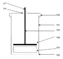
- FIG. 1 is a diagram illustrating a vertical cross-section along the symmetry axis of one embodiment of the bioparticle capture device, before use.
- FIG. 2 is a diagram illustrating a vertical cross-section along the symmetry axis of one embodiment of the bioparticle capture device, when the device has been dipped, without being totally immersed, in a container containing the bioparticle suspension to be treated for a time sufficient for retaining the bioparticles on the surface of the filter membrane.
- FIG. 3 is a diagram illustrating a vertical cross-section along the symmetry axis of one embodiment of the bioparticle capture device, after retention of the bioparticles on the filter membrane, when the piston rod is actuated for exerting a pressure on the absorbent block, so as to generate a liquid flow to the outside of the device aiming at removing the bioparticles from the filter membrane.
- the arrows represent the direction to which the piston is actuated.
- FIG. 4 shows photon microscopy images of a cytological preparation transferred onto a glass slide, provided by a biological sample obtained from cervical cytology sample.
- the cytological preparation has then been fixed in a liquid medium of the PRESERVCYT® type, and thereafter submitted to a staining step according to the PARANICOLAOU method.
- FIG. 4A illustrates a cytological preparation obtained with the device of the invention.
- FIG. 4B illustrates a cytological preparation obtained with an automated system provided with a suction chamber under vacuum. Samples presented on FIGS. 4A and 4B are derived from the same cervical cytology sample.
- FIG. 5 is a diagram illustrating a vertical cross-section along the symmetry axis of one embodiment of the bioparticle capture device, immediately after having dipped said device in a container containing the biological fluid to be analyzed.
- FIG. 6 is a diagram illustrating a vertical cross-section along the symmetry axis of one embodiment of the bioparticle capture device, when the device has been dipped, without being totally immersed, in a container containing the bioparticle suspension to be treated, for a time sufficient to retain the bioparticles on the surface of the filter membrane.
- FIG. 7 is a diagram illustrating a vertical cross-section along the symmetry axis of one embodiment of the bioparticle capture device, after retention of the bioparticles on the filter membrane, when the piston rod is actuated for exerting a pressure on the absorbent block, so as to generate a liquid flow to the outside of the device aiming at removing the bioparticles from the filter membrane.
- the bioparticles previously adsorbed onto the surface of the filter membrane are transferred from the filter membrane onto the surface of a cytological analysis support, for example onto the surface of a microscope slide.
- the arrows represent the direction to which the piston is actuated.
- FIG. 8 is a diagram illustrating a particular embodiment of the rod ( 107 ).
- FIG. 9 is a diagram illustrating a view of the upper part of one embodiment of the tube ( 101 ), which geometry has been specially adapted to receive the rod ( 107 ) according to the embodiment illustrated on FIG. 8 .
- FIG. 10 is a diagram illustrating a partial view of a multi-assay platform in vertical cross-section along the symmetry axis, immediately after having dipped the devices included in said platform into a plurality of containers containing a biological fluid to be analyzed.
- the applicant focused on developing a new device for capturing suspended biological particles in a liquid medium, essentially in order to prepare biological samples for cytological analysis.
- the applicant sought to develop a new device of the hereabove type, which would be less expensive than the known devices and would simultaneously enable to obtain biological samples which quality would be at least equivalent to that of biological samples prepared with the known devices.
- the applicant Upon researching, the applicant demonstrated that it was possible to obtain biological samples of a very high quality, in particular for a subsequent cytological analysis, with a filter membrane device wherein a liquid flow going through the filter is generated due to the absorption of said liquid by a hydrophilic absorbent agent placed immediately downstream the filter membrane, in the liquid flow direction.
- a hydrophilic absorbent agent of the type having a suitable absorbency a liquid flow is produced which force or flow rate is sufficient for carrying away the bioparticles contained in a sample to be tested towards the filter membrane of the device in a stationary condition, therefore without requiring any displacement related to the stationary device immersed into the test sample, with respect to said sample.
- FIGS. 1 to 4 a first embodiment of which is illustrated on FIGS. 1 to 4 and a second embodiment of which is illustrated on FIGS. 5 to 7 .
- a specific embodiment of the device is more especially illustrated on FIGS. 8 and 9 .
- the device of the invention for capturing suspended biological particles in a liquid medium is first of all described hereafter by referring to the drawings on FIGS. 1 and 5 .
- a “biological particle” is intended to mean any solid particle insoluble in an aqueous liquid medium which might be present in a biological material collected on the body of an animal or a plant multicellular living organism, advantageously an animal multicellular living organism, preferably a mammal, including humans.
- the bioparticles encompass tissue micro-fragments, possible microorganisms, living cells, dead cells, anucleated cell bodies such as erythrocytes and platelets (thrombocytes), fragments, cell debris, as well as possible crystals and light solid foreign bodies.
- the biological particles thus encompass any substance insoluble in an aqueous liquid medium, including insoluble protein substances, such as pectin or protein substances derived from fibronectin, for example protein substances derived from fetal fibronectin which represent a clinical parameter indicating a risk for preterm delivery.
- insoluble protein substances such as pectin or protein substances derived from fibronectin
- protein substances derived from fetal fibronectin which represent a clinical parameter indicating a risk for preterm delivery.
- the device of the invention is described hereafter in more detail, in particular through the description of a plurality of specific structural characteristics and, if applicable, of technical effects resulting from those structural characteristics.
- Various embodiments of the device of the invention are described hereafter, referring especially to the illustration of the miscellaneous structural characteristics shown on the figures.
- a particular embodiment of the device of the invention may comprise only one of the numerous specific technical characteristics that will be detailed hereunder, or many combined specific characteristics.
- the figures illustrate embodiments of the device of the invention wherein several of the specific technical characteristics detailed hereafter are combined, each of which may be present individually or in combination with one or more other specific characteristics, in the device of the invention.
- capturing biological particles by means of the device of the invention is performed (i) by dipping at least the filter membrane containing-end of the device into the liquid medium containing suspended bioparticles, without the upper end of the device being itself immersed, and (ii) by maintaining the device in said liquid, preferably in a fully stationary position within said liquid, for a time sufficient for capturing the particles on the filter membrane thanks to a liquid flow resulting from the absorption of said liquid by the block of absorbent agent.
- the absorbent agent consists in a hydrophilic absorbent agent which progressively swells as increases the volume of absorbed liquid, as is shown for example on each of FIGS. 2 and 6 .
- the applicant observed that the swelling of the absorbent agent goes on, even after the device has been withdrawn from the liquid containing the suspended bioparticles therein.
- the applicant believes that after the device has been withdrawn from the liquid containing the particles suspended therein, the persistence of the absorbent agent swelling enables the reduced volume of liquid to be absorbed upon contacting the filter membrane, in particular upon contacting the outer surface of the filter membrane, said reduced volume of liquid being taken away together with the device, in particular due to surface tension force as well as to the force of the liquid flow generated by the block of absorbent material.
- the swelling of the block of absorbent material which can be observed after withdrawal of the device of the invention from the liquid medium comprising the bioparticles is able to generate a residual suction pull towards the tube inside ( 101 ), which goes through the filter membrane ( 102 ), and which helps retaining efficiently the bioparticles on the outer surface of said filter membrane ( 102 ), without simultaneously altering the physical integrity of said biological particles.
- the block ( 103 ) of absorbent agent is made of a hydrophilic material that swells when contacting a liquid medium, in particular an aqueous liquid medium.
- the block of absorbent agent has an absorption capacity of aqueous liquid media of at least twice its own dry weight and more preferably up to at least three or four times its own dry weight.
- the block of absorbent agent can swell to a two-fold increase in volume through absorption of a liquid medium, and more preferably to an at least three- or four-fold increase in volume, as compared to its initial dry volume.
- the dimensions of the block ( 103 ) of absorbent material are adapted for enabling an easy insertion of the block ( 103 ) into the tube ( 101 ).
- the dimensions of the block ( 103 ) are adapted so that the block ( 103 ) can be easily displaced along the tube ( 101 ).
- the block ( 103 ) of absorbent material is inserted at the end of the tube ( 101 ) intended to receive the plug ( 105 ) and gets positioned upon contacting the filter membrane ( 102 ) simply due to gravity.
- the swelling properties of the block ( 103 ) of absorbent material are such that the outer wall of the block ( 103 ) does not quickly come in contact with the inner wall of the tube ( 101 ), but rather swells in the direction of its vertical axis by pushing the piston back towards the upper part of the tube ( 101 ), generally after 15 to 20 seconds following the immersion of the lower end of the device provided with the filter membrane ( 102 ).
- the dimensions of the block ( 103 ) are such that they require forced insertion and displacement of the block ( 103 ) in the tube ( 101 ) until the block ( 103 ) be positioned at the other end of the tube ( 101 ) in contact with the filter membrane ( 102 ).
- the time required once the lower end of the device has been dipped may vary.
- a block ( 103 ) of absorbent material For manufacturing a block ( 103 ) of absorbent material, the person skilled in the art may use any type of hydrophilic absorbent agent having the swelling properties described hereabove, which is commonly commercially available.
- the one skilled in the art may use an absorbent agent made of viscose, preferably of a compressed viscose material.
- an absorbent agent made of viscose, preferably of a compressed viscose material.
- a viscose material in the form of a textile “non woven” lap of viscose, folded on itself again and again, so as to form a suitably sized laminated block of viscose.
- said laminated viscose block is submitted to a compression step so as to obtain a compressed, laminated viscose block with outstanding absorbance properties due to (i) the viscose's high capacity to absorb aqueous liquid media and (ii) the liquid suction force resulting from the high increase in volume of the compressed viscose when contacting an aqueous liquid medium.
- a super-absorbent agent for obtaining a block ( 103 ) of absorbent agent, one may use a super-absorbent agent, well known from the one skilled in the art.
- the person skilled in the art may use a super-absorbent agent of the hydrogel type.
- a hydrophilic absorbent agent a polymer of the crosslinked sodium polyacrylate polymer type, which may be obtained through a polymerization reaction of acrylic acid combined with sodium hydroxide in the presence of a polymerization initiator.
- Crosslinked sodium polyacrylate-based super-absorbent agents are known per se and are broadly commercially available.
- an absorbent agent of the super-absorbent type it may also be used a copolymer of polyacrylamide, a copolymer of maleic anhydride and ethylene, crosslinked carboxymethyl cellulose, copolymers of polyvinyl alcohol, or crosslinked polyethylene oxide.
- the swelling capacity of the hereabove mentioned super-absorbent agents is variable but corresponds to at least 10 or at least 20 times the dry volume thereof.
- the swelling capacity of a super-absorbent agent of the crosslinked sodium polyacrylate type may reach 30 to 60 times the dry volume thereof.
- the tube ( 101 ), the plug ( 105 ), the piston ( 104 ) and the filter membrane ( 102 ) are of a conventional type.
- the tube ( 101 ) fitted with the filter membrane ( 102 ) may be of the type of those which are commonly used as filters for use in biological sample treatment automated systems for cytological analysis.
- the filter membrane simply adheres to or is welded to the thickness of the wall of one of the ends of the tube ( 101 ).
- the tube ( 101 ), as well as the rod ( 107 ) and the piston ( 104 ) bearing means ( 108 ) may be made of any type of plastics, including polyvinyl chloride (PVC), polystyrene or polyethylene.
- PVC polyvinyl chloride
- polystyrene polystyrene
- the tube ( 101 ) comes as a monoblock, which may be made for example through a molding process.
- piston ( 104 ) bearing means ( 108 ) may be made of another material, for example elastomer, latex or silicone.
- the filter membrane consists in a filter for cell filtration of a known type in the field of cytology, for example a polyester filter or a polycarbonate filter.
- a filter for cell filtration of a known type in the field of cytology
- a polyester filter or a polycarbonate filter for example a polyester filter or a polycarbonate filter.
- suitable filter membranes marketed by the Millipore company (Billerica, Mass., United States).
- a filter membrane may be used, having a given pore size, selected in the range from 1 ⁇ m to 25 ⁇ m.
- a filter membrane having a given pore size selected in the range from 1.5 ⁇ m to 2.5 ⁇ m, preferably of 2 ⁇ m.
- the filter membrane reference n° 7060-2511 marketed by the Whatman-GE Healthcare company may be used for example.
- the device of the invention can capture all the interesting bioparticles for a subsequent cytological analysis, whatever the tissue nature or origin of the initial biological sample that was collected.
- a filter membrane having a given pore size selected in the range from 3 ⁇ m to 10 ⁇ m, preferably of 5 ⁇ m or 7 ⁇ m or 8 ⁇ m.
- the filter membrane reference n° TMTP-02500 marketed by the Millipore company may be used for example.
- the filter membrane reference n° TTT-P02500 marketed by the Millipore company may also be used.
- Filter membranes Cyclopore® PC marketed by the Whatman-GE Healthcare company may also be used, such as 5 ⁇ m membranes (Ref. 7060-2513; 7060-4713), 8 ⁇ m membranes (Ref.
- the device of the invention can only retain cells with a large size, for example of the type of epithelial cells contained in an initial biological sample from a vaginal sample or a cervico-vaginal smear.
- the device of the invention enables the capture of bioparticles which are carried away towards the filter membrane ( 102 ) exclusively by the liquid flow generated by the suction pull force resulting from the swelling of the block ( 103 ) of absorbent material contained in the device in a stationary condition, in order to subsequently carry out the cytological preparations which quality is at least as good as that of the cytological preparations obtained with the known devices.
- the device of the invention may be performed a large diversity of cytological preparations according to methods that are known per se, for example by transferring the bioparticles adsorbed onto the surface of the filter membrane into an analysis medium or onto a suitable analysis support.
- the bioparticles adsorbed onto the surface of the filter membrane may be for example transferred to an analysis liquid medium, for example of the type comprising a substance for fixing biological particles, including a cell fixation agent.
- said bioparticles may be transferred onto the surface of a biological analysis support, for example onto the surface of a glass slide.
- the cytological preparations obtained with the device of the invention enable to preserve the physical or biological integrity of the bioparticles contained in the test sample.
- the preservation of the physical or biological integrity of the bioparticles present in the final cytological preparation is also due to the fact that the bioparticles adsorbed onto the surface of the filter membrane ( 102 ) are then simply transferred to the surface of the cytological analysis support, generally a glass plate, by contacting the surface of the filter membrane with the surface of the cytological analysis support and by transferring the bioparticles of the first to the second surface by just exerting a short pressure onto the piston, for example for 0.5 to 5 seconds.
- the transfer of the bioparticles from the filter membrane of the device to the analysis medium, for example to the surface of the cytological analysis support may thus be effected by a simple contact, without requiring any pressure of the filter membrane ( 102 ) to the surface of the cytological analysis support. Indeed, pressing the filter membrane ( 102 ) onto the cytological analysis support, so as to transfer the biological particles from said filter membrane to the surface of said support, would cause at least part of the bioparticles to collapse, where such physical damaging of the bioparticles might produce poor quality final cytological preparations and, at worst might substantially alter diagnosis results.
- the piston ( 104 ) of the device of the invention slides inside the tube ( 101 ) along an axis which is parallel to the axis of the cylinder wall of said tube ( 101 ).
- the device of the invention does not comprise any special means to force the sliding of the piston ( 104 ) along the expected axis, because the sliding axis of the piston ( 104 ) is determined as being perpendicular to the upper surface of the block ( 103 ) of absorbent material.
- the device of the invention comprises at least one special means to force the sliding of the piston ( 104 ) along the expected axis, as for examples in the embodiments of the device illustrated respectively on FIGS. 1 and 5 .
- the second end of the tube ( 101 ) is closed by a plug ( 105 ) comprising a central hole ( 106 ).
- the rod ( 107 ) of the piston ( 104 ) slides, through the central hole ( 106 ), from either side of the plug wall ( 105 ).
- the central hole ( 106 ) acts as a sliding guide for the rod ( 107 ) so as to ensure a vertical sliding of the latter, along an axis parallel to the wall of tube ( 101 ).
- the rod ( 107 ) of the piston ( 104 ) slides vertically, along an axis which is parallel to the axis of the walls of the tube ( 101 ) thanks to the presence of a disk ( 110 ) fixed on the rod ( 107 ).
- This particular embodiment of the device will be described in more detail further in the present description.
- the geometry of the device of the invention and in particular the geometry of the horizontal cross-section of the tube ( 101 ), may be very varied.
- the tube ( 101 ) has a horizontal circular cross-section and as such the tube ( 101 ) is cylindrical.
- the block ( 103 ) of absorbent material also has preferably a cylindrical form.
- the diameter of the block ( 103 ) of absorbent material is slightly lower than the tube ( 101 ) inner wall diameter, so that the outer wall of the block ( 103 ) of absorbent material be not in contact with the inner wall of the tube ( 101 ), once the lower end of the device is immersed in the container containing the bioparticle suspension.
- the block ( 103 ) of absorbent material is fixed at the end of the tube ( 101 ) fitted with the filter membrane ( 102 ) without requiring any special fixing means.
- the block ( 103 ) is fixed by simple gravity.
- the positioning of the block ( 103 ) is further improved through the piston ( 104 ) weight, the bearing means ( 108 ) of which may be initially positioned to contact the upper surface of the block ( 103 ).
- the positioning of the block ( 103 ) may also be ensured through a gentle, direct manual or mechanical pressure on the rod ( 107 ).
- the block ( 103 ) is fixed due to the combined gravitational force and to the bearing force of the block ( 103 ) wall onto the inner surface of the tube ( 101 ) wall.
- the horizontal cross-section of the tube ( 101 ) may be oval, square, rectangular or other. It goes without saying that for simply practicity's sake as regards ease of construction and use, the preferred embodiment of the device of the invention is that with the circular tube ( 101 ) cross-section, the tube ( 101 ) being therefore of cylindrical form.
- a tube ( 101 ) having a cylindrical form includes embodiments wherein the tube ( 101 ) is strictly cylindrical just on part of height thereof, where said tube ( 101 ) may have a composite form and further comprise, in addition to a cylindrical section, also at least one tapered section. It should be noted that a tube ( 101 ) having, like the one illustrated on FIG. 5 , a cylindrical section topped by a tapered section has, on all the height thereof, and whatever the section considered, a horizontal circular cross-section.
- the dimensions of the piston ( 104 ) bearing means ( 108 ) are chosen so that the piston ( 104 ) moves freely along the vertical axis of the tube ( 101 ).
- the edges of the piston ( 104 ) bearing means ( 108 ) are not continuously contacting the surface of the inner wall of the tube ( 101 ).
- This particular characteristic of the device of the invention means that a gas or a liquid flow can freely flow between (i) the lower compartment of the tube ( 101 ) delimited by the filter membrane ( 102 ) and the lower surface of the piston ( 104 ) bearing means ( 108 ), (ii) the upper compartment of the tube ( 101 ) delimited by the upper surface of the piston ( 104 ) bearing means ( 108 ) and the upper end of the tube ( 101 ) located at the plug ( 105 ) and (iii) the outer atmosphere with which the inner volume communicates through the central hole ( 106 ) of the plug ( 105 ).
- the piston ( 104 ) bearing means ( 108 ) is advantageously circular and its diameter is slightly lower than the inner wall diameter of the tube ( 101 ), so as to ensure an easy displacement of the piston along the vertical axis of the tube ( 101 ).
- the present invention includes the embodiment wherein the tube ( 101 ) inner wall diameter is 21 mm and the piston ( 104 ) bearing means ( 108 ) diameter is 20 mm.
- FIGS. 5 to 7 Another particular embodiment of the device of the invention for capturing suspended bioparticles in a liquid medium is illustrated, during the different steps of a method for implementing the same, on FIGS. 5 to 7 .
- this particular embodiment of the device of the invention comprises an upper part expanded as a funnel, which promotes the stability thereof within the liquid in which said device is dipped when used for an analysis, for example a cytological analysis of a biological tissue sample.
- the tube ( 101 ) comprises two sections forming a continuous outer surface, respectively:
- the device of the invention was placed in a container ( 120 ) filled with a liquid ( 121 ) to be analyzed.
- a liquid ( 121 ) to be analyzed.
- the outer surface of the tapered section (S 2 ) of the tube ( 101 ) comes to rest, because of the gravitational force, leaning on the container ( 120 ) edges ( 122 ), so as to block the vertical movement of the tube ( 101 ) at a given position within the container ( 120 ).
- the containers adapted for analyzing biological samples possess determined standard dimensions.
- the dimensions of the device of the invention, and in particular those of the tapered section S 2 as well as those of the tube ( 101 ) total height may be determined beforehand to be adapted to each conventionally used biological analysis container.
- the height H 1 of the section S 1 represents at least two thirds of the total height H of the tube ( 101 ).
- said tube comprises in addition an annular shoulder at its upper end.
- the end with the largest diameter of the section S 2 of the tube ( 101 ) comprises a flat, annular shoulder ( 111 ) which plane lies perpendicularly to the edges of the section S 1 of said tube ( 101 ).
- the shoulder ( 11 ) forms a flat section, that is to say an annular surface which plane lies perpendicularly to the vertical axis of the tube ( 101 ) and which inner diameter coincides with the largest diameter of the tapered section S 2 .
- the end of the section S 2 and the shoulder ( 115 ) form a continuous outer surface.
- the dimensions of the tube ( 101 ) are chosen so that (i) the external diameter of the end with the largest diameter of the section S 2 be lower than the inner diameter of the vertical walls of the container ( 120 ) and so that (ii) the external diameter of the annular shoulder ( 115 ) be higher than the inner diameter of the vertical walls of the container ( 120 ).
- the surface of the shoulder ( 115 ) is in contact with the upper edges of the container ( 120 ) (not shown on FIG. 5 ).
- the distance between the outer surface of the membrane ( 102 ) of the tube ( 101 ) and the surface of the bottom of the container ( 120 ) is determined by the difference between (i) the height H which is the sum of heights H 1 and H 2 respectively of sections S 1 and S 2 , and (ii) the height between (ii- 1 ) the junction of the container ( 120 ) vertical wall with the inner surface of the bottom of said container and (ii- 2 ) the upper edges of the container ( 120 ) walls.
- the rod ( 107 ) of the piston ( 104 ) is fitted with a disk ( 110 ) which is placed in an intermediate position between the bearing means ( 108 ) and the upper end of the rod ( 107 ).
- a disk ( 110 ) which is placed in an intermediate position between the bearing means ( 108 ) and the upper end of the rod ( 107 ).
- FIG. 8 One embodiment of this type of piston ( 104 ) is shown in detail on FIG. 8 .
- said device is characterized in that a disk ( 110 ) is fixed on the rod ( 107 ), the diameter of said disk ( 110 ) being determined so that it enables the guiding of the rod ( 107 ) along an axis parallel to the walls of the tube ( 101 ).
- the disk ( 110 ) enables the piston ( 104 ) to slide along an axis which is maintained vertical for all the stroke of said piston.
- some embodiments of the device of the invention have the rod ( 107 ) of the piston ( 104 ) fitted with a disk ( 110 ).
- said piston comprises a plunger means ( 111 ) intended to transmit a vertical supporting force, from the top to the bottom of the piston, so as to transfer the bioparticles adsorbed onto the filter membrane to the medium or to the cytological analysis support, or even to release part of the liquid that may be contained in the tube ( 101 ), in particular in the block of absorbent material.
- the vertical supporting force which is exerted through the plunger means ( 111 ) is transmitted in a substantially uniform manner to the whole surface of the pusher means ( 108 ), thanks to one or more reinforcements ( 113 ).
- Each reinforcement ( 113 ) (i) forms an integral part, on one of sides thereof, of the rod ( 107 ) wall, and (ii) forms an integral part, on a third side, of the upper surface of the pusher means ( 108 ).
- a reinforcement ( 113 ) is triangular with one of the three sides thereof fixed to the outer wall of the rod ( 107 ) and another of the three sides thereof fixed to the upper surface of the pusher means ( 108 ).
- a reinforcement ( 113 ) comes as a square.
- the length of the reinforcement ( 113 ) side which forms an integral part of the pusher means ( 108 ) represents at least half the distance, more preferably at least two thirds thereof, separating (i) the outer edge of the pusher means ( 108 ) from (ii) the wall of the end of the rod ( 107 ) which is fixed to the pusher means ( 108 ).
- the piston ( 104 ), when fitted with reinforcements ( 113 ), comprises preferably at least two, and more preferably at least four, reinforcements ( 113 ).
- the number of reinforcements ( 113 ) may be 2, 3, 4, 5 or 6 reinforcements.
- the presence of the reinforcements ( 113 ) ensures the transmission of an upper pressure substantially uniformly to the whole surface of the block ( 103 ) of hydrophilic absorbent material when using the device, and enables therefore to release the liquid contained in the device, through the filter membrane ( 102 ), with a pressure substantially uniformly distributed on the whole surface of the filter membrane ( 102 ).
- the detachment of the bioparticles that may have been previously adsorbed on the surface of the filter membrane ( 102 ), to be transferred to the medium or to the cytological analysis support is also effected in a substantially uniformly manner, from the whole outer surface of said filter membrane ( 102 ), generally to the surface of the cytological analysis support.
- FIG. 9 is a diagram of the upper end of the tube ( 101 ) of FIG. 5 , facing the end on which the filter membrane ( 102 ) is fixed.
- FIG. 9 shows the upper end of the tube ( 101 ) which includes:
- a series of protruding elements or pins is arranged in the central part of the section 51 of the tube ( 101 ).
- This specific series of protruding elements or pins may aim at stopping the piston ( 104 ) in an intermediate height position, which makes possible to stop the volume expansion of the block of absorbent material at the desired height, and therefore at a desired volume level, in the tube ( 101 ). Stopping the volume expansion of the block of absorbent material causes the sample liquid flow towards the device of the invention to be discontinued and thus stops the adsorption of additional bioparticles on the surface of the filter membrane.
- the piston ( 104 ) is inserted into the inside of the tube ( 101 ), if applicable by applying an angle between the axis of the rod ( 107 ) and the vertical axis of the tube ( 101 ), so as to engage the pusher means ( 108 ) without difficulty.
- This embodiment which includes the combination of (i) a piston ( 104 ) comprising a disk ( 110 ) provided with one or more slots ( 112 ) and (ii) a tube ( 101 ) comprising a shoulder ( 116 ) provided with one or more corresponding protruding elements ( 117 ), enables an easy engagement of the piston ( 104 ) into the inside of the tube ( 101 ), and simultaneously prevents any unwanted disengagement of said piston ( 104 ).
- the probability is low that once the piston ( 104 ) is engaged into the inside of the tube ( 101 ), the one or more slots ( 112 ) and the one or more corresponding protruding elements ( 117 ) coincide again, which would cause the disengagement of said piston.
- the device of the invention is provided with a series of protruding elements or pins on the central part of the Section S 1 of the tube ( 101 ), the vertical movement of the piston ( 104 ) resulting from the volume expansion of the block of absorbent material is stopped because of the piston disk ( 110 ) contacting said protruding elements or pins.
- the pusher means ( 108 ) also comprises one or more slots ( 112 ), generally which size and position are the same as those of the slots ( 112 ) present on the disk ( 110 ).
- the one or more slot(s) ( 112 ) of the disk ( 110 ) and the one or more slot(s) of the pusher means ( 108 ) are each vertically aligned to one another, along the main axis of the rod ( 107 ).
- the one or more slot(s) of the pusher means ( 108 ) are offset from each other, along the main axis of the rod ( 107 ), which further reduces the risk of disengagement of the piston ( 104 ).
- the engagement of the piston ( 104 ) into the inside of the tube ( 101 ) is easy, without increasing the risk of disengagement of said piston.
- the device of the invention such as configured at the beginning of step a) of the hereabove method is illustrated respectively on each of FIGS. 1 and 5 .
- the container containing the bioparticle suspension is of a known type, for example a flask traditionally used for conditioning cell or tissue samples for biological analyses, including cytological and histological analyses.
- the liquid medium containing the suspended biological particles is of a known type.
- said liquid consists in an aqueous buffered liquid containing a substance for fixing suspended cells or cell bodies.
- a fixation agent are alcohol based mixtures.
- said liquid may consist in a saline buffer medium, preferably in a suitable cell culture medium.
- said liquid may consist in a natural body fluid such as urine, or in a pathologically secreted body fluid, like an ascite, an effusion, a cyst or a flow.
- the time duration of step a) is variable. It corresponds to the time required for the device of the invention to move from its store position to the position contacting the bioparticle suspension to be treated.
- step b) generally the end of the tube ( 101 ) provided with the filter membrane ( 102 ) only needs to be in contact with the liquid medium and the totality of the outer surface of the filter membrane be immersed in said liquid medium.
- a liquid medium flow is then generated through the filter membrane ( 102 ) to the inside of the tube ( 101 ), and more particularly towards the block ( 103 ) of absorbent material which is positioned at this end of the tube ( 101 ).
- the incoming liquid medium flow is generated both (i) through the surface tension force resulting from the surface energy characteristics of the block ( 103 ) of absorbent material and (ii) through the suction mechanical action of the liquid medium resulting from the gradual increase in volume of the absorbent material that constitutes the block ( 103 ).
- step b) the incoming liquid medium flow carries bioparticles away to the inside of the tube ( 101 ), the particles being, depending on the nature of the initial biological sample and on the pore size of the filter membrane ( 102 ), for all or for part only retained on the outer surface of the filter membrane ( 102 ) in contact with the liquid medium.
- step b) may be easily adapted by the person skilled in the art, by taking all the various criteria into account, such as (i) the expected final density of the bioparticles retained on the filter membrane, (ii) the concentration of suspended bioparticles in the initial liquid medium and (iii) the absorption capacity of the block ( 103 ) of absorbent material.
- the time duration of step a) is of at least 5 seconds, a time required for generating the incoming liquid flow towards the inner volume of the tube ( 101 ) causing the capture of a minimal number of sufficient bioparticles on the surface of the filter membrane ( 102 ).
- step b) a time duration of step b) ranging from 5 seconds to several minutes, depending on the nature of the initial biological sample, and in particular on the concentration of suspended bioparticles in the initial liquid medium.
- the time duration of step b) may be conditioned by the clogging of the filter membrane pores by the particles, which causes the absorption to be almost completely stopped and the particles to come as thin layers, without requiring any sophisticated measuring device.
- step b) the position of the device is as illustrated on the drawing of each of FIGS. 2 and 6 .
- the device of the invention is presented immersed in the container containing the suspended bioparticles in a liquid medium.
- the block ( 103 ) of absorbent material increased in volume, with respect to its dry state initial volume illustrated on each of FIGS. 1 and 5 .
- the bioparticles ( 109 ), initially suspended in the liquid medium and thereafter retained, are illustrated on the outer surface of the filter membrane ( 102 ) on FIG. 2 .
- the piston ( 104 ) which bearing means ( 108 ) still contacts the upper surface of the block ( 103 ) of absorbent material, moved to its upper position as a consequence of the absorbent material swelling.
- the bioparticles retained on the outer surface of the filter membrane ( 102 ) may be recovered and treated according to traditional methods of cytological analysis, for example transfer through replica plating, by applying a pressure of the piston on the block ( 103 ), from the filter membrane ( 102 ) towards the surface of a micro slide, then optionally subsequent implementation of a preparation staining step, prior to performing the cytological analysis, such analysis being generally carried out through photon microscopy.
- analyzing a cell preparation obtained by means of the device of the invention shows that the cell integrity is often equally or even better preserved than compared with a preparation made using a known device.
- the particles stopped by the filter membrane lead to a lower deceleration of the particles and simultaneously to a lower alteration, or even no alteration, of their physical integrity.
- the use of the device of the invention has other advantages, in particular when the initial biological sample consists in a sample said to be “hemorrhagic”, in which large amounts of fibrinous concretions are present.
- cytological preparations are typically obtained that are difficult to analyze on micro slides due to the presence of numerous fibrinous concretions that are carried away towards the filter together with the interesting biological particles.
- the use of the device of the invention is also advantageous during a surgery, for example during an ultrasound-guided fine-needle aspiration biopsy in an extemporaneous examination. It will be possible to indicate to the operator if the collected liquid sample is satisfying, making it possible to repeat the procedure if the quality of the collected sample was insufficient.
- Aspiration biopsies include those for mammary nodules, hepatic metastases or tumors in deep organs. Such a use of the device of the invention enables to reduce the risk of repeated surgical procedures, which invasive aspect causes unnecessary traumatisms in patients.
- the device of the invention is used in methods for making cytological preparations.
- the present invention also relates to a method for making a cytological preparation from a liquid medium containing suspended bioparticles, comprising the following steps of:
- step d) of the hereabove method for making cytological preparations a pressure is exerted onto the block ( 103 ) by actuating the piston ( 104 ), so as to generate a liquid flow coming out from the inside of the device ( 101 ) to the outside, said liquid flow causing the bioparticles initially retained on the filter membrane to be carried away.
- This particular embodiment of the method is illustrated on each of FIGS. 3 and 7 .
- the interesting bioparticles are recovered and thereafter submitted to one or more steps so as to be pre-treated before their cytological analysis.
- the particles retained on the filter membrane ( 102 ) of the device of the invention, in step d), are recovered according to a method traditionally used by the anatomical pathologists, such as a transfer through replica plating from the filter membrane to the surface support of a micro slide, such as the micro slide ( 200 ) illustrated on FIG. 7 .
- the biological preparation generally the cell preparation, which adheres to the surface of the micro slide may then be submitted to one or more steps so as to be pre-treated prior to observation, for example one or more steps of specific or non-specific staining, including staining steps with May-Gr ⁇ umlaut over (m) ⁇ wald Giemsa, the so called “Papanicolaou” staining, staining with alum carmine, eosine, erythrosine, Schorr staining, basic fuschin, Mayer's hemalum, haematein, haematoxylin, Sudan black, mucicarmin, nigrosin, orcein, phloxin b, xylidine Ponceau, Schiff's reagent, Congo red, etc.
- specific or non-specific staining including staining steps with May-Gr ⁇ umlaut over (m) ⁇ wald Giemsa, the so called “Papanicolaou” staining, staining with alum carmine, e
- step d) of the method of the invention for making a cytological preparation at least part of the bioparticles are transferred from the filter membrane of the device to the surface of a cytological analysis support, by contacting said filter membrane with the surface of said cytological analysis support.
- said method comprises the following additional step: e) performing the staining of the biological particles transferred onto the surface of said cytological analysis support.
- step d) of the method of the invention for making a cytological preparation at least part of the bioparticles are transferred from the filter membrane of the device to a suitable container, for example a cell culture tube, so as to obtain a cytological preparation in the form of a cell concentrated suspension.
- a suitable container for example a cell culture tube
- the cell concentrated suspension obtained at the end of step d) may then be submitted to one or more subsequent treatment steps, prior to the cytological analysis.
- the cell concentrated suspension obtained at the end of step d) may be incubated in the presence of detectable antibodies, specific to membrane markers or to intracellular markers, prior to the cytological analysis which may be carried out for example using a flow cytometry method, if applicable after an additional incubation with the labeled antibodies.
- the cell concentrated suspension obtained at the end of step d) may then be treated using molecular biology methods, for example through in situ hybridization using specific nucleic probes or through RNA extraction, then quantization of the expression level of one or more interesting genes, or through DNA extraction, then detection of the mutations within the sequence of one or more interesting genes.
- molecular biology methods for example through in situ hybridization using specific nucleic probes or through RNA extraction, then quantization of the expression level of one or more interesting genes, or through DNA extraction, then detection of the mutations within the sequence of one or more interesting genes.
- step d) of the method of the invention for making a cytological preparation at least part of the bioparticles retained on the filter membrane are recovered by scraping said filter membrane.
- the filter membrane ( 102 ) it is possible to separate the filter membrane ( 102 ) from the rest of the device, and to perform the embedding of the whole filter membrane/bioparticles retained in the paraffin.
- Scraping the filter membrane may be effected by any suitable device of a known type.
- any suitable device of a known type such as one may use spatulas traditionally used in cell culture for suspending cultured cells which adhere to the culture support, these spatulas being also called “cell scrapers”.
- tissue micro-fragments have to be recovered so as to be analyzed.
- micro-fragments thus recovered may then be embedded in paraffin, or in any other type of suitable resin, for making histological sections which will be studied through microscopy techniques, if applicable after having been submitted to one or more suitable histochemical staining or immunohistochemical staining steps.
- These embodiments of the method of the invention are very especially implemented for performing cytological analyses of bioparticles collected from mucous tissue by scraping.
- the device of the invention enables to recover tissue and cell micro-fragments to be later histologically analyzed.
- This aspect of the device is particularly useful, in view of the increasing development of sampling techniques by needle biopsy or scraping or cytological brushing of tissues, with methods using automated guiding procedures in endoscopies assisted with medical imaging systems.
- this kind of sampling which is nowadays more and more practiced enables to collect sample materials said to be “mixed”, also called “cyto-biopsical” materials.
- cyto-biopsical There are composite biological materials comprising both full size cells and tissue micro-fragments.
- a multi-assay platform comprising a plurality of devices of the invention, said multi-assay platform having been conceived for simultaneously making a plurality of cytological preparations from initial biological samples.
- FIG. 10 which is a vertical cross-section of a partial view of a multi-assay platform of the invention, said platform comprises a plurality of bioparticle capture devices which are arranged in a determined manner on the surface of said platform.
- FIG. 10 shows a series of three aligned devices of the invention in the multi-assay platform.
- said multi-assay platform comprises a plurality of bioparticle capture devices which are aligned.
- the multi-assay platform advantageously comprises a number of bioparticle capture devices of at least 2 and of not more than 100.
- “Of at least 2” is intended to include at least 3, 4, 5, 6, 7, 8, 9, 10, 11, 12, 13, 14, 15, 16, 17, 18, 19, or 20. “Of not more than 100” is intended to include at most 99, 98, 97, 96, 95, 94, 93, 92, 91, 90, 85, 80, 75, 70, 65, 60, 55, 50, 45, 40, 35, 30, 25, 24, 23, 22, 21 or 20.
- said platform comes in the form of an array comprising a plurality of bioparticle capture devices arranged to each other along a single linear axis.
- the plurality of bioparticle capture devices are arranged both along a plurality of lines that are parallel to each other and along a plurality of columns that are parallel to each other and perpendicular to the lines.
- Each line and each column comprises a plurality of bioparticle capture devices.
- the multi-assay platform may have a square form.
- each line or each column advantageously comprises a number of bioparticle capture devices of minimum 2 and of maximum 100.
- the bioparticle capture devices are all included in a structure of the monoblock type.
- the wall of a first tube ( 101 ) and the wall of a second tube ( 101 ) near to the first tube are connected to each other through the upper surface of the platform.
- (a) the wall of a first tube ( 101 ), (b) the wall of a second tube ( 101 ) near to the first tube and (b) the surface of the platform connecting both walls to each other form a continuous outer surface, which materializes the structure of the monoblock type of said platform.
- the structure of the multi-assay platform including the walls of each of the tubes ( 101 ) included therein may be made by simply molding a polymer material such as polyethylene, polystyrene or polypropylene, using methods that are well known from the person skilled in the art.
- a filter membrane ( 102 ) is then mounted, supported by both tubes ( 101 ).
- each of the tubes ( 101 ) is then fitted with a block ( 103 ) of absorbent material, prior to positioning a piston ( 104 ).
- the structure of the platform comes in the form of a plate in which a plurality of recesses have been arranged in a well-ordered manner, each recess being intended to receive a bioparticle capture device, according to its general embodiment described in details hereabove in the present description.
- the number and the space arrangement of the recesses in the multi-assay platform structure includes the possibilities described previously for the space arrangement of tubes ( 101 ) included in the platform of the monoblock type.
- each bioparticle capture device included in the multi-assay platform is intended to be introduced into a container containing a biological sample to be tested.
- the arrangement of the containers should be compatible with the arrangement of the devices included in the multi-assay platform.
- the containers containing the biological samples to be tested are advantageously installed beforehand in a sample rack, making it possible to arrange said containers in a compatible position with respect to the devices within the multi-assay platform.
- the positioning of the tubes as sampling containers in the sample rack is “compatible” with the arrangement of the devices included in the multi-assay platform when each of said devices contained in the platform can be introduced into each of the containers arranged in said sample rack.
- the multi-assay platform may comprise a higher number of bioparticle capture devices as compared to the number of containers actually arranged in the sample rack. In such a situation, a cytological analysis of all the samples contained in said containers may be performed, even if all the devices contained in the multi-assay platform are not used.
- bioparticle capture devices in the multi-assay platform as containers in the corresponding sample rack.
- the multi-assay platform of the invention can be used in the same way as a bioparticle capture device, which has already been detailed hereabove in the present description.
- the present invention further relates to a multi-assay platform comprising a plurality of bioparticle capture devices such as defined in the present description.
- said multi-assay platform comes in the form of a monoblock structure.
- the present invention further relates to a system for capturing suspended bioparticles in a liquid medium, said system comprising the combination of two elements:
- the present invention also relates to a method for making a cytological preparation from a liquid medium containing suspended bioparticles, comprising the following steps of:
Landscapes
- Health & Medical Sciences (AREA)
- Chemical & Material Sciences (AREA)
- Life Sciences & Earth Sciences (AREA)
- General Health & Medical Sciences (AREA)
- Engineering & Computer Science (AREA)
- Biotechnology (AREA)
- Bioinformatics & Cheminformatics (AREA)
- Analytical Chemistry (AREA)
- Organic Chemistry (AREA)
- Wood Science & Technology (AREA)
- Zoology (AREA)
- Biochemistry (AREA)
- Genetics & Genomics (AREA)
- Chemical Kinetics & Catalysis (AREA)
- Sustainable Development (AREA)
- Microbiology (AREA)
- Biomedical Technology (AREA)
- Hematology (AREA)
- Clinical Laboratory Science (AREA)
- General Engineering & Computer Science (AREA)
- Physics & Mathematics (AREA)
- General Physics & Mathematics (AREA)
- Immunology (AREA)
- Pathology (AREA)
- Sampling And Sample Adjustment (AREA)
- Apparatus Associated With Microorganisms And Enzymes (AREA)
- Separation Using Semi-Permeable Membranes (AREA)
- Investigating Or Analysing Biological Materials (AREA)
Applications Claiming Priority (3)
| Application Number | Priority Date | Filing Date | Title |
|---|---|---|---|
| FR0855210A FR2934681B1 (fr) | 2008-07-29 | 2008-07-29 | Dispositif pour la capture de particules biologiques et utilisation. |
| FR0855210 | 2008-07-29 | ||
| PCT/FR2009/051497 WO2010012941A2 (fr) | 2008-07-29 | 2009-07-24 | Dispositif pour la capture de particules biologiques et utilisation |
Publications (2)
| Publication Number | Publication Date |
|---|---|
| US20110159533A1 US20110159533A1 (en) | 2011-06-30 |
| US8992861B2 true US8992861B2 (en) | 2015-03-31 |
Family
ID=40532519
Family Applications (1)
| Application Number | Title | Priority Date | Filing Date |
|---|---|---|---|
| US13/056,743 Active 2030-09-29 US8992861B2 (en) | 2008-07-29 | 2009-07-24 | Bioparticle capture device, and use thereof |
Country Status (12)
| Country | Link |
|---|---|
| US (1) | US8992861B2 (zh) |
| EP (1) | EP2310826B1 (zh) |
| JP (1) | JP5425200B2 (zh) |
| CN (1) | CN102165303B (zh) |
| AU (1) | AU2009275747B2 (zh) |
| BR (1) | BRPI0916650A2 (zh) |
| CA (1) | CA2732553C (zh) |
| ES (1) | ES2650249T3 (zh) |
| FR (1) | FR2934681B1 (zh) |
| IL (1) | IL210794A0 (zh) |
| RU (1) | RU2516522C2 (zh) |
| WO (1) | WO2010012941A2 (zh) |
Cited By (1)
| Publication number | Priority date | Publication date | Assignee | Title |
|---|---|---|---|---|
| US20140110356A1 (en) * | 2012-10-19 | 2014-04-24 | Warsaw Orthopedic, Inc. | Filtration device |
Families Citing this family (19)
| Publication number | Priority date | Publication date | Assignee | Title |
|---|---|---|---|---|
| US8313644B2 (en) * | 2010-01-13 | 2012-11-20 | OZOlab | Bottle with an integrated filtration assembly that is manually operated using a plunger |
| CN103813845B (zh) * | 2011-07-22 | 2016-08-17 | 生物梅里埃有限公司 | 从培养物离析微生物的方法和试剂盒 |
| CN103063500B (zh) * | 2011-10-19 | 2015-06-17 | 封江南 | 悬浮细胞染色装置 |
| EP2912458B1 (en) | 2012-10-24 | 2018-07-18 | NYU Winthrop Hospital | Non-invasive biomarker to identify subjects at risk of preterm delivery |
| WO2014202957A1 (en) * | 2013-06-19 | 2014-12-24 | Brightwake Limited | Cell collecting device |
| ES2718069T3 (es) * | 2014-04-30 | 2019-06-27 | Merck Patent Gmbh | Dispositivo para preparación de muestras y método para preparar una muestra para pruebas de esterilidad |
| EP3228249B1 (en) | 2014-10-14 | 2019-02-06 | Becton, Dickinson and Company | Blood mixing and transfer device |
| EP4261523A3 (en) | 2014-10-14 | 2023-12-06 | Becton, Dickinson and Company | Blood sample management using open cell foam |
| CN105388189B (zh) * | 2015-10-15 | 2019-07-09 | 思澜科技(成都)有限公司 | 用于生物组织检测的手动吸附式辅助器皿 |
| CN106323689B (zh) * | 2016-08-22 | 2020-02-21 | 中国食品发酵工业研究院有限公司 | 一种以水质监测为导向的痕量极性有机污染物捕集器 |
| FR3056294B1 (fr) * | 2016-09-20 | 2020-02-14 | Kabcyt | Dispositif de capture de particules biologiques |
| CN109141973B (zh) * | 2017-06-28 | 2021-09-21 | 西安市宇驰检测技术有限公司 | 固定污染源大气中酸雾的收集装置和方法 |
| KR20200109293A (ko) | 2017-09-13 | 2020-09-22 | 프로제너티, 인크. | 자간전증 바이오마커 및 관련된 시스템 및 방법 |
| KR102081509B1 (ko) * | 2018-08-24 | 2020-02-25 | 고려대학교 산학협력단 | 양방향 막 투과 이동 제어를 이용한 다공성막 기반 입자 분리 장치 |
| EP4070113A4 (en) | 2019-12-04 | 2023-12-20 | Biora Therapeutics, Inc. | ASSESSMENT OF PREECAMPSIA USING FREE AND DISSOCIATE PLACENTAL GROWTH FACTOR ASSAYS |
| CN111875092B (zh) * | 2020-07-14 | 2022-03-04 | 北部湾大学 | 一种渔业养殖尾水处理装置 |
| CN113943640A (zh) * | 2021-10-18 | 2022-01-18 | 海南马良师傅网络科技有限公司 | 一种生物粒子捕集实验设备及其用途 |
| CN115290387B (zh) * | 2022-08-06 | 2023-04-14 | 东莞市国丰粮油有限公司 | 一种适用于面粉加工的质量安全控制系统 |
| CN115253377B (zh) * | 2022-08-15 | 2024-04-30 | 三江原子农业科技有限公司 | 一种茶多酚连续分离提取工艺及提取设备 |
Citations (25)
| Publication number | Priority date | Publication date | Assignee | Title |
|---|---|---|---|---|
| US4553553A (en) | 1982-03-13 | 1985-11-19 | Boehringer Mannheim Gmbh | Device for the detection of bacteria, fungi, and viruses in blood |
| US4945921A (en) * | 1987-08-21 | 1990-08-07 | Okimoto Paul M | Body cavity specimen collecting and testing apparatus |
| US4953561A (en) * | 1989-09-18 | 1990-09-04 | Cancer Diagnostics, Inc. | Urine testing module and method of collecting urine antigen |
| JPH02248836A (ja) | 1989-02-17 | 1990-10-04 | Remedia Ag | 医療診断のために流体から粒子を分離・収集するための方法およびその装置 |
| DE3924862A1 (de) | 1989-07-27 | 1991-01-31 | Kuehn Hermann Prof Dr Dr Med | Ausstrichtupfer und diesem angepasstes zentrifugenroehrchen |
| US5139031A (en) | 1989-09-18 | 1992-08-18 | La Mina Ltd. | Method and device for cytology and microbiological testing |
| JPH06501101A (ja) | 1991-04-18 | 1994-01-27 | ラ マイナ リミテッド | 液体試料容器と取付け可能な試験モジュール |
| JPH06300752A (ja) | 1993-04-13 | 1994-10-28 | Showa Yakuhin Kako Kk | 分離用具 |
| JPH076746U (ja) | 1993-06-29 | 1995-01-31 | 武藤化学薬品株式会社 | プレパラート作製用細胞分離器 |
| JPH07103971A (ja) | 1993-10-01 | 1995-04-21 | Taiho Ind Co Ltd | 検体採取方法および検体採取装置 |
| JPH0862210A (ja) | 1994-08-22 | 1996-03-08 | Muto Kagaku Yakuhin Kk | 液状検体細胞塗抹器具及びその使用方法 |
| JPH08508395A (ja) | 1992-07-28 | 1996-09-10 | ラ マイナ インコーポレイテッド | 細胞学検査用単層採取のための方法と装置 |
| JPH11505714A (ja) | 1995-05-25 | 1999-05-25 | セヴァーン トレント ウォーター リミテッド | 濾過及び培養の方法並びに装置 |
| DE29919827U1 (de) | 1999-03-23 | 2000-03-23 | Draeger Sicherheitstech Gmbh | Vorrichtung zur Probenahme von Flüssigkeiten |
| WO2002048681A2 (en) | 2000-12-04 | 2002-06-20 | Molecular Diagnostics, Inc. | Cell transfer device |
| WO2003091704A2 (fr) | 2002-04-24 | 2003-11-06 | Alphagenics International Sarl | Dispositif pour la realisation d'une preparation cytologique sur une lame porte-objet |
| US6774151B2 (en) * | 1999-08-30 | 2004-08-10 | Sca Hygiene Products Ab | Method of producing an absorbent foam material |
| JP2004245831A (ja) | 2003-01-21 | 2004-09-02 | Denka Seiken Co Ltd | メンブレンアッセイ法 |
| US6887681B2 (en) * | 2000-03-31 | 2005-05-03 | Neogen Corporation | Apparatus and methods for chemiluminescent assays |
| FR2869413A1 (fr) | 2004-04-21 | 2005-10-28 | Michel Marie Francois Guiu | Appareil et procede de preparation de lames de cytologie en milieu liquide |
| JP2006006125A (ja) | 2004-06-22 | 2006-01-12 | Nipro Corp | 骨髄単核細胞の調製方法及び細胞調製装置 |
| US20070211563A1 (en) * | 2003-12-01 | 2007-09-13 | Broockeville Corporation N.V. | Two-Component Mixing and Dispensing Device |
| US20070284300A1 (en) | 2006-06-08 | 2007-12-13 | Bidlingmeyer Brian A | Removing material from liquid sample within a sample vessel |
| DE202007017400U1 (de) | 2007-12-13 | 2008-02-28 | Ballnath, Rainer | Vorrichtung zur Gewinnung eines Teilchenkonzentrats aus einer Flüssigkeit |
| WO2008076623A2 (en) | 2006-12-13 | 2008-06-26 | Cytyc Corporation | Method and system for collecting cells of a biological specimen |
Family Cites Families (7)
| Publication number | Priority date | Publication date | Assignee | Title |
|---|---|---|---|---|
| US4653510A (en) * | 1982-03-01 | 1987-03-31 | Accu-Med Corporation | Apparatus for collecting and/or growing protected biological cultures |
| FR2654836B1 (fr) * | 1989-11-17 | 1994-01-28 | Biotrol Sa Laboratoires | Appareil d'execution automatique d'un immunodosage en plusieurs etapes successives d'au moins une substance biologique dans une pluralite d'echantillons biologiques, procede et reactif mettant en óoeuvre ledit appareil. |
| US6149871A (en) * | 1997-08-25 | 2000-11-21 | Lamina, Inc. | System for processing multiple specimens of biological fluid |
| JPH11215979A (ja) * | 1998-02-02 | 1999-08-10 | Daiken Iki Kk | 微生物の検査装置および検査キット |
| DE19820178C2 (de) * | 1998-04-29 | 2000-11-30 | Rainer Ballnath | Vorrichtung zur Anreicherung von Teilchen in Körperflüssigkeit |
| FR2795515B1 (fr) * | 1999-06-08 | 2004-02-20 | Commissariat Energie Atomique | Plate-forme d'analyse chimique ou biologique a microbalances, dispositif et procede d'analyse utilisant la plate-forme |
| SE9904539D0 (sv) * | 1999-12-10 | 1999-12-10 | Alphahelix Ab | Method and device for the handling of samples and reagents |
-
2008
- 2008-07-29 FR FR0855210A patent/FR2934681B1/fr active Active
-
2009
- 2009-07-24 RU RU2011107308/05A patent/RU2516522C2/ru active
- 2009-07-24 ES ES09740383.6T patent/ES2650249T3/es active Active
- 2009-07-24 CA CA2732553A patent/CA2732553C/fr active Active
- 2009-07-24 US US13/056,743 patent/US8992861B2/en active Active
- 2009-07-24 EP EP09740383.6A patent/EP2310826B1/fr active Active
- 2009-07-24 BR BRPI0916650A patent/BRPI0916650A2/pt not_active Application Discontinuation
- 2009-07-24 JP JP2011520565A patent/JP5425200B2/ja not_active Expired - Fee Related
- 2009-07-24 CN CN200980138034.4A patent/CN102165303B/zh active Active
- 2009-07-24 AU AU2009275747A patent/AU2009275747B2/en active Active
- 2009-07-24 WO PCT/FR2009/051497 patent/WO2010012941A2/fr active Application Filing
-
2011
- 2011-01-23 IL IL210794A patent/IL210794A0/en unknown
Patent Citations (30)
| Publication number | Priority date | Publication date | Assignee | Title |
|---|---|---|---|---|
| US4553553A (en) | 1982-03-13 | 1985-11-19 | Boehringer Mannheim Gmbh | Device for the detection of bacteria, fungi, and viruses in blood |
| US4945921A (en) * | 1987-08-21 | 1990-08-07 | Okimoto Paul M | Body cavity specimen collecting and testing apparatus |
| US5160704A (en) | 1989-02-17 | 1992-11-03 | Remedia Ag | Method and apparatus for collecting and separating particles from fluid for medical diagnosis |
| JPH02248836A (ja) | 1989-02-17 | 1990-10-04 | Remedia Ag | 医療診断のために流体から粒子を分離・収集するための方法およびその装置 |
| DE3924862A1 (de) | 1989-07-27 | 1991-01-31 | Kuehn Hermann Prof Dr Dr Med | Ausstrichtupfer und diesem angepasstes zentrifugenroehrchen |
| US5139031A (en) | 1989-09-18 | 1992-08-18 | La Mina Ltd. | Method and device for cytology and microbiological testing |
| US4953561A (en) * | 1989-09-18 | 1990-09-04 | Cancer Diagnostics, Inc. | Urine testing module and method of collecting urine antigen |
| JPH06500403A (ja) | 1991-04-08 | 1994-01-13 | ラ マイナ リミテッド | 生物試料の捕集試験装置及び捕集試験方法 |
| JPH06501101A (ja) | 1991-04-18 | 1994-01-27 | ラ マイナ リミテッド | 液体試料容器と取付け可能な試験モジュール |
| US5429803A (en) | 1991-04-18 | 1995-07-04 | Lamina, Inc. | Liquid specimen container and attachable testing modules |
| JPH08508395A (ja) | 1992-07-28 | 1996-09-10 | ラ マイナ インコーポレイテッド | 細胞学検査用単層採取のための方法と装置 |
| JPH06300752A (ja) | 1993-04-13 | 1994-10-28 | Showa Yakuhin Kako Kk | 分離用具 |
| JPH076746U (ja) | 1993-06-29 | 1995-01-31 | 武藤化学薬品株式会社 | プレパラート作製用細胞分離器 |
| JPH07103971A (ja) | 1993-10-01 | 1995-04-21 | Taiho Ind Co Ltd | 検体採取方法および検体採取装置 |
| US5484572A (en) | 1993-10-01 | 1996-01-16 | Taiho Industries Co., Ltd. | Apparatus for collecting medical test specimens |
| JPH0862210A (ja) | 1994-08-22 | 1996-03-08 | Muto Kagaku Yakuhin Kk | 液状検体細胞塗抹器具及びその使用方法 |
| JPH11505714A (ja) | 1995-05-25 | 1999-05-25 | セヴァーン トレント ウォーター リミテッド | 濾過及び培養の方法並びに装置 |
| DE29919827U1 (de) | 1999-03-23 | 2000-03-23 | Draeger Sicherheitstech Gmbh | Vorrichtung zur Probenahme von Flüssigkeiten |
| US6774151B2 (en) * | 1999-08-30 | 2004-08-10 | Sca Hygiene Products Ab | Method of producing an absorbent foam material |
| US6887681B2 (en) * | 2000-03-31 | 2005-05-03 | Neogen Corporation | Apparatus and methods for chemiluminescent assays |
| WO2002048681A2 (en) | 2000-12-04 | 2002-06-20 | Molecular Diagnostics, Inc. | Cell transfer device |
| WO2003091704A2 (fr) | 2002-04-24 | 2003-11-06 | Alphagenics International Sarl | Dispositif pour la realisation d'une preparation cytologique sur une lame porte-objet |
| US20050169809A1 (en) | 2002-04-24 | 2005-08-04 | Jean-Luc Centeleghe | Device for producing a cytological preparation on an object-carrying slide |
| JP2004245831A (ja) | 2003-01-21 | 2004-09-02 | Denka Seiken Co Ltd | メンブレンアッセイ法 |
| US20070211563A1 (en) * | 2003-12-01 | 2007-09-13 | Broockeville Corporation N.V. | Two-Component Mixing and Dispensing Device |
| FR2869413A1 (fr) | 2004-04-21 | 2005-10-28 | Michel Marie Francois Guiu | Appareil et procede de preparation de lames de cytologie en milieu liquide |
| JP2006006125A (ja) | 2004-06-22 | 2006-01-12 | Nipro Corp | 骨髄単核細胞の調製方法及び細胞調製装置 |
| US20070284300A1 (en) | 2006-06-08 | 2007-12-13 | Bidlingmeyer Brian A | Removing material from liquid sample within a sample vessel |
| WO2008076623A2 (en) | 2006-12-13 | 2008-06-26 | Cytyc Corporation | Method and system for collecting cells of a biological specimen |
| DE202007017400U1 (de) | 2007-12-13 | 2008-02-28 | Ballnath, Rainer | Vorrichtung zur Gewinnung eines Teilchenkonzentrats aus einer Flüssigkeit |
Non-Patent Citations (2)
| Title |
|---|
| International Search Report, dated Feb. 11, 2010, from corresponding PCT application. |
| Translation of Japanese Office Action, dated Jun. 18, 2013, from corresponding JP application. |
Cited By (2)
| Publication number | Priority date | Publication date | Assignee | Title |
|---|---|---|---|---|
| US20140110356A1 (en) * | 2012-10-19 | 2014-04-24 | Warsaw Orthopedic, Inc. | Filtration device |
| US9333447B2 (en) * | 2012-10-19 | 2016-05-10 | Warsaw Orthopedic, Inc. | Filtration device |
Also Published As
| Publication number | Publication date |
|---|---|
| CA2732553A1 (fr) | 2010-02-04 |
| AU2009275747A1 (en) | 2010-02-04 |
| FR2934681B1 (fr) | 2011-09-30 |
| JP5425200B2 (ja) | 2014-02-26 |
| EP2310826A2 (fr) | 2011-04-20 |
| CN102165303B (zh) | 2016-02-17 |
| FR2934681A1 (fr) | 2010-02-05 |
| AU2009275747B2 (en) | 2015-07-30 |
| JP2011529573A (ja) | 2011-12-08 |
| WO2010012941A2 (fr) | 2010-02-04 |
| CN102165303A (zh) | 2011-08-24 |
| US20110159533A1 (en) | 2011-06-30 |
| WO2010012941A3 (fr) | 2010-03-25 |
| CA2732553C (fr) | 2016-08-30 |
| EP2310826B1 (fr) | 2017-09-06 |
| ES2650249T3 (es) | 2018-01-17 |
| BRPI0916650A2 (pt) | 2015-11-17 |
| RU2516522C2 (ru) | 2014-05-20 |
| IL210794A0 (en) | 2011-04-28 |
| RU2011107308A (ru) | 2012-09-10 |
Similar Documents
| Publication | Publication Date | Title |
|---|---|---|
| US8992861B2 (en) | Bioparticle capture device, and use thereof | |
| JP4372322B2 (ja) | 複合生物流体試料の液体成分から成形成分を分離する方法およびアセンブリ | |
| AU645689B2 (en) | Liquid specimen container and attachable testing modules | |
| EP3008162B1 (en) | Method for separation of sporadic cells from body fluids, and apparatus for carrying out said method | |
| US20120196344A1 (en) | Cytoblock preparation system and methods of use | |
| US9557251B2 (en) | Cell pathology tubes and associated cell processing methods | |
| US8137903B2 (en) | Method for magnetic separation of red blood cells from a patient sample | |
| CN111811901B (zh) | 一种细胞块采集装置和细胞块采集方法 | |
| JP6571694B2 (ja) | 生体試料用の試料ホルダ | |
| JPH05501965A (ja) | 羊水サンプルを採取する方法および装置 | |
| US11187631B2 (en) | Device for capturing biological particles | |
| US20020106718A1 (en) | Cell transfer device | |
| KR101840081B1 (ko) | 세포학적 표본 준비장치 | |
| OA19553A (en) | Device for capturing biological particles. | |
| EP3365654A2 (en) | Filtration apparatus |
Legal Events
| Date | Code | Title | Description |
|---|---|---|---|
| STCF | Information on status: patent grant |
Free format text: PATENTED CASE |
|
| AS | Assignment |
Owner name: KABCYT SAS, FRANCE Free format text: ASSIGNMENT OF ASSIGNORS INTEREST;ASSIGNOR:KARKOUCHE, BASTIEN;REEL/FRAME:039481/0904 Effective date: 20160422 |
|
| MAFP | Maintenance fee payment |
Free format text: PAYMENT OF MAINTENANCE FEE, 4TH YR, SMALL ENTITY (ORIGINAL EVENT CODE: M2551); ENTITY STATUS OF PATENT OWNER: SMALL ENTITY Year of fee payment: 4 |
|
| MAFP | Maintenance fee payment |
Free format text: PAYMENT OF MAINTENANCE FEE, 8TH YR, SMALL ENTITY (ORIGINAL EVENT CODE: M2552); ENTITY STATUS OF PATENT OWNER: SMALL ENTITY Year of fee payment: 8 |