US8420203B2 - Surface structure for a working device - Google Patents
Surface structure for a working device Download PDFInfo
- Publication number
- US8420203B2 US8420203B2 US13/218,486 US201113218486A US8420203B2 US 8420203 B2 US8420203 B2 US 8420203B2 US 201113218486 A US201113218486 A US 201113218486A US 8420203 B2 US8420203 B2 US 8420203B2
- Authority
- US
- United States
- Prior art keywords
- elements
- grip area
- height
- surface structure
- grip
- Prior art date
- Legal status (The legal status is an assumption and is not a legal conclusion. Google has not performed a legal analysis and makes no representation as to the accuracy of the status listed.)
- Active
Links
Images


Classifications
-
- B—PERFORMING OPERATIONS; TRANSPORTING
- B25—HAND TOOLS; PORTABLE POWER-DRIVEN TOOLS; MANIPULATORS
- B25G—HANDLES FOR HAND IMPLEMENTS
- B25G1/00—Handle constructions
- B25G1/10—Handle constructions characterised by material or shape
-
- Y—GENERAL TAGGING OF NEW TECHNOLOGICAL DEVELOPMENTS; GENERAL TAGGING OF CROSS-SECTIONAL TECHNOLOGIES SPANNING OVER SEVERAL SECTIONS OF THE IPC; TECHNICAL SUBJECTS COVERED BY FORMER USPC CROSS-REFERENCE ART COLLECTIONS [XRACs] AND DIGESTS
- Y10—TECHNICAL SUBJECTS COVERED BY FORMER USPC
- Y10T—TECHNICAL SUBJECTS COVERED BY FORMER US CLASSIFICATION
- Y10T428/00—Stock material or miscellaneous articles
- Y10T428/24—Structurally defined web or sheet [e.g., overall dimension, etc.]
- Y10T428/24355—Continuous and nonuniform or irregular surface on layer or component [e.g., roofing, etc.]
-
- Y—GENERAL TAGGING OF NEW TECHNOLOGICAL DEVELOPMENTS; GENERAL TAGGING OF CROSS-SECTIONAL TECHNOLOGIES SPANNING OVER SEVERAL SECTIONS OF THE IPC; TECHNICAL SUBJECTS COVERED BY FORMER USPC CROSS-REFERENCE ART COLLECTIONS [XRACs] AND DIGESTS
- Y10—TECHNICAL SUBJECTS COVERED BY FORMER USPC
- Y10T—TECHNICAL SUBJECTS COVERED BY FORMER US CLASSIFICATION
- Y10T428/00—Stock material or miscellaneous articles
- Y10T428/24—Structurally defined web or sheet [e.g., overall dimension, etc.]
- Y10T428/24479—Structurally defined web or sheet [e.g., overall dimension, etc.] including variation in thickness
-
- Y—GENERAL TAGGING OF NEW TECHNOLOGICAL DEVELOPMENTS; GENERAL TAGGING OF CROSS-SECTIONAL TECHNOLOGIES SPANNING OVER SEVERAL SECTIONS OF THE IPC; TECHNICAL SUBJECTS COVERED BY FORMER USPC CROSS-REFERENCE ART COLLECTIONS [XRACs] AND DIGESTS
- Y10—TECHNICAL SUBJECTS COVERED BY FORMER USPC
- Y10T—TECHNICAL SUBJECTS COVERED BY FORMER US CLASSIFICATION
- Y10T74/00—Machine element or mechanism
- Y10T74/20—Control lever and linkage systems
- Y10T74/20576—Elements
- Y10T74/20732—Handles
- Y10T74/2078—Handle bars
- Y10T74/20828—Handholds and grips
Definitions
- the present invention relates to a surface structure for a working device.
- This surface structure is intended to ensure a good gripping of the surface; in particular, the structure is suitable for use as the surface of a handle.
- the following may be considered “working devices” in the sense of the invention described and claimed herein: non-motor-driven and motor-driven devices, craftsmen's tools, household devices, including in particular motor-driven household devices (handheld blenders, hand mixers, immersion blenders), wet razors, electric shavers, hair care devices (hair dryers, curling irons, straightening irons), and devices for removing hair (in particular depilating devices).
- the invention also relates to a working device having such a surface structure.
- U.S. Pat. No. 1,690,557 discloses a wet razor having a metallic handle.
- This handle has the shape of a cylindrical rod, and has raised parts on its surface.
- Such raised parts can be produced by applying a pattern of parallel lines.
- the raised parts then have a diamond-shaped base, and appear as small pyramids.
- the pattern depicted is applied uniformly over the entire gripping surface.
- Such a pattern is primarily suitable for metallic surfaces.
- the grip adhesion is not optimal. Because the raised parts all have the same height, the fingers do not have as much hold, in particular as soon as a finger slides off.
- DE 10 2004 052 681 A1 discloses a handle that is intended to be suitable for a large number of devices.
- This handle has so-called acupressure features that are adapted to fit the inner surface of the hand.
- This handle is therefore intended to be held in a very particular position. If the device is held differently, it is difficult to grasp. In fact, when held differently this device provides an even less secure and comfortable grip than a smooth handle.
- the advantage of proposing a particular way of holding the handle is therefore achieved at the cost of poor suitability of the handle for other ways of holding it.
- EP 1 127 529 A1 discloses a vacuum cleaner having a handle segment.
- This handle segment is produced by the combination of a harder plastic material and a softer, more graspable plastic material.
- the softer plastic material protrudes past the hard plastic surface in the form of knobs.
- the knobs therefore provide a degree of security to the grasping hand.
- grasping comfort is greatest when the vibrations that almost unavoidably occur due to the electrical operation of the device are transferred to the hand only to a limited extent.
- the disclosed surface made of hard plastic which is much larger than the surface of the knobs, will however probably result in a significant transmission of vibration.
- the present invention seeks to improve the prior art and to provide an improved surface structure for a working device.
- This surface structure is intended to enable a secure grip while allowing different holding positions, while nonetheless providing an optimal holding position.
- this surface structure is intended to transmit vibrations of the working device only to a limited extent.
- a surface structure having these advantages is the surface structure claimed in Claim 1 .
- the surface structures in the subclaims offer specific advantages.
- the surface structure has at least three elements, namely a first element, a second element, and a third element.
- Such elements may have any shape, as long as they can be distinguished from the surface structure.
- the elements may be recesses in the surface structure, but as a rule are raised parts.
- the elements have a base surface. To the extent that the elements are formed integrally with the surface structure, the base surface results from extrapolation of the surface in the vicinity of the elements.
- the elements also have at least one side surface.
- an element may have the shape of a segment of a sphere.
- the element then has, in addition to the base surface, only one limiting surface. This surface on the sphere surface is designated here as a side surface.
- the element can also be pyramid-shaped. It then has, for example, four side surfaces.
- the elements have a certain height. This height is measured from the highest point of the element to the base surface. (For elements that represent recesses, the lowest point below the surface would correspondingly be used, but the value obtained should however also be referred to as the height.)
- the surface structure has different grip areas. These grip areas may be adjacent to one another or arranged at a distance from one another.
- the elements are aligned on a dot matrix.
- a dot matrix may for example be determined by the points of intersection of two sets of parallel lines. In this case, four adjacent points enclose a diamond. If the sets of parallel lines are situated perpendicular to one another, four adjacent points enclose a rectangle or square. It is also possible to produce a dot matrix using curved lines.
- the centers of the second elements and the centers of the third elements are now arranged on the points of the dot matrix.
- the center of an element is understood to be the center of gravity of the element, given homogenous mass of the element.
- the element is considered limited by a base surface that may in turn result from extrapolation of the surface in the vicinity of the element.
- the centers of the first elements are not arranged on the dot matrix.
- the centers of the first elements can be arranged on the connecting lines between points of the dot matrix.
- the first grip area contains first elements and second elements, wherein the second grip area predominantly contains second elements and the third grip area predominately contains third elements.
- the dot matrix is produced by parallel lines. This results in a dot matrix that is easy to define, promoting easy realization of the present invention, and also offering cost advantages with regard to machine-based implementation of the invention. Moreover, such a dot matrix can define grip areas in a particularly easily visible manner, thus promoting intuitive grasping in an ergonomically advantageous manner.
- the second grip area contains three times as many second elements as first elements.
- the second grip area is set off particularly clearly from the first grip area.
- the first elements in the first grip area can allow a particularly secure grip.
- the third elements are mathematically similar to the second elements; i.e., the third elements are essentially miniaturizations of the second elements.
- the third elements are essentially miniaturizations of the second elements.
- the development of the invention according to Claim 5 provides that the height of the second elements in the second grip area decreases continuously as the distance from the first grip area becomes greater.
- the continuous decrease in height in turn allows a particularly smooth transition of the grip area, and thus provides a certain degree of tolerance with regard to ways of holding the handle that are not completely ideal. Especially when a working device is grasped quickly, the hand will not always immediately find the ideal holding position.
- the development of the invention according to Claim 6 provides that the height of the first elements (h 1 ) is less than the height of the second elements (h 2 ). According to this development, there is a particularly advantageous transition between the second grip area and the first grip area. The highest elements in the first grip area are then also elements having the height h 2 . The maximum height in the first grip area and in the second grip area will then also equally be determined by the second elements. However, a firmly grasped hand will also contact the first elements. Therefore, even if height h 1 is lower than height h 2 , the first grip area will be the most likely to offer a particularly secure grasp.
- the height (h 1 ) of the first elements is in turn greater than the height (h 3 ) of the third elements.
- the height (h 3 ) of the third elements is lower than the height (h 1 ) of the first elements, and, according to the invention, is also lower than the height (h 2 ) of the second elements. Therefore, these third elements act more as auxiliary elements helping to avoid excess slipperiness of the surface. Intuitively, however, the user of the surface structure will not grasp the handle in the area of the third elements if their height is particularly low.
- the height of the third elements in the third grip area decreases continuously as the distance from the first grip area increases. In this way, an aesthetically pleasing surface can be produced that, however, in order to increase operating safety, does not provide grasping only or predominantly in the third grip area.
- the angle of the first and/or second and/or third elements between the respective base surface of the elements and at least one side surface of the elements is less than 45°.
- this condition is fulfilled by that angle between the base surface and the side surface of the elements that is measured furthest from the center of the first grip area.
- the corresponding angle may also be smaller than 30° or smaller than 20° or smaller than 10°.
- this condition is also met by that angle between the base surface and side surface of the elements, the angle between the base surface and that side surface is measured that is situated farthest from the apex of the curve.
- the corresponding angle may also be smaller than 30° or smaller than 20° or smaller than 10°.
- the first elements are selected such that they are symmetrical to their longitudinal axis. This again results in elements that have a secure grip and that are aesthetically pleasing.
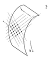
- FIG. 1 shows a three-dimensional top view of a surface that, however, does not have all the features of a surface structure according to the invention
- FIG. 2 shows a view of the type shown in FIG. 1 , which also does not have all the features of a surface structure according to the invention, in which in particular the dot matrix is shown,
- FIG. 3 shows a three-dimensional top view of a surface structure according to the invention
- FIG. 4 shows a cross-section through the structure shown in FIG. 3 .
- FIG. 5 shows a cross-section of an alternative surface structure according to the invention
- FIG. 6 shows a perspective top view providing a good view of the appearance of the invention.
- FIG. 1 shows a surface suitable for the arrangement of first elements ( 11 ), second elements ( 12 ), and third elements ( 13 ) in a first grip area ( 21 ), a second grip area ( 22 ), and a third grip area ( 23 ) (these elements not already being shown in the Figure).
- first a dot matrix is to be provided on the surface.
- This dot matrix can be produced through sets of parallel lines. Depicted is a first set 31 of parallel lines and a second set 32 of parallel lines. The respective lines from the first and second set are perpendicular to one another and are equidistant from one another. In this way, a dot matrix is produced in which each four points enclose a square.
- the depicted surface has a direction W along which it is curved and a direction F in which it is flat.
- FIG. 2 shows the dot matrix 34 , which was obtained using the parallel lines from FIG. 1 , without again showing these lines.
- FIG. 3 shows a surface structure 10 according to the invention.
- This surface structure is arranged on the surface known from FIGS. 1 and 2 , which is curved along the direction W and runs flat along the direction F.
- a first grip area 21 is arranged in the center of the depicted segment.
- a second grip area 22 Adjacent thereto is a second grip area 22 , and adjacent thereto in turn is a third grip area 23 .
- First grip area 21 contains a number of first elements 11 in the form of pyramids on a quadratic base surface. The center of the base surface is situated in each case on a point of the dot matrix. In first grip area 21 , first elements 11 are arranged along the connecting lines between each two points of the dot matrix. The first elements 11 are shorter in height than the second elements 12 . The first elements 11 are symmetrical about their longitudinal axis, and this longitudinal axis is oriented such that in each case it connects two points of the dot matrix.
- the second grip area 22 contains only second elements 12 , and does not contain any first elements 11 .
- the depicted second elements 12 are identical in shape to the second elements 12 in the first grip area 21 .
- the third grip area 23 contains third elements 13 . These elements are also pyramid-shaped. Like the second elements 12 , the third elements 13 are pyramids on a quadratic base surface. Here, the third elements 13 are similar, even in the mathematical sense, to elements 12 , so that they are miniaturizations of the second elements 13 .
- FIG. 4 shows a cross-section through FIG. 3 .
- the surface normal N runs through the center of the first grip area 21 .
- first elements 11 having the height h 1 are arranged, as are second elements 12 having the height h 2 .
- the height h 2 is greater than height h 1 .
- second elements 12 are provided in the adjacent second grip area 22 . They have the same height h 2 as do the second elements in first grip area 21 .
- third elements 13 are provided having the height h 3 .
- the height h 3 is less than height h 2 .
- the height h 2 is constant in the entire second grip area
- the height h 3 is constant in the entire third grip area.
- a continuous decrease in the heights is also conceivable.
- the height of the second elements can continuously decrease already within the first grip area 21 , and this decrease can continue in the second grip area 22 .
- the height of the second elements can also continuously decrease in the direction of the transition to the third grip area 23 in such a way that at the transition between the two grip areas, the third elements 13 have the same height as the adjacent second elements.
- FIG. 5 shows a view of the type shown in FIG. 4 , in which another embodiment of the invention is shown.
- First elements 11 and second elements 12 are arranged in the first grip area 21 . These second elements have an angle ⁇ between the base surface and the side surface. The angle ⁇ is measured in each case at the side surface that is oriented away from the center of the first grip area.
- the second elements 12 are also shown in the second grip area 22 . In these elements, the corresponding angle ( ⁇ 1) is smaller than in the first grip area.
- third elements 13 are shown in the third grip area. In these elements, the corresponding angle ( ⁇ 2) is in turn smaller than in the second grip area.
- the size of angle ⁇ thus decreases as the distance increases from the apex of the angle to the center of the first grip area. This distance can be measured by angle ⁇ . In the context of the present invention, it can be advantageous for the angle ⁇ to decrease by the amount of the corresponding angle ⁇ as the distance from the apex increases.
- FIG. 6 shows a perspective view of a segment of a surface structure according to the invention.
- an area 21 is particularly suitable as a grip area.
- These parts of the hand are situated in areas 22 and 23 , and make the grip more secure.
- the connection between the working device and the grasping hand is however not as secure.
- the depicted grip pattern is intuitive insofar as the thumb will generally always be placed on area 21 in order to exert high pressure there.
- it is also possible to apply another finger or another area of the hand to area 21 so that the surface structure permits a large number of gripping positions.
Landscapes
- Engineering & Computer Science (AREA)
- Mechanical Engineering (AREA)
- Mechanical Control Devices (AREA)
- Golf Clubs (AREA)
- Superstructure Of Vehicle (AREA)
Applications Claiming Priority (4)
| Application Number | Priority Date | Filing Date | Title |
|---|---|---|---|
| DE102009015432 | 2009-03-28 | ||
| DE102009015432.9 | 2009-03-28 | ||
| DE102009015432A DE102009015432A1 (de) | 2009-03-28 | 2009-03-28 | Oberflächenstruktur für ein Arbeitsgerät |
| PCT/IB2010/051240 WO2010113064A1 (en) | 2009-03-28 | 2010-03-22 | Surface structure for a working device |
Related Parent Applications (1)
| Application Number | Title | Priority Date | Filing Date |
|---|---|---|---|
| PCT/IB2010/051240 Continuation WO2010113064A1 (en) | 2009-03-28 | 2010-03-22 | Surface structure for a working device |
Publications (2)
| Publication Number | Publication Date |
|---|---|
| US20110311777A1 US20110311777A1 (en) | 2011-12-22 |
| US8420203B2 true US8420203B2 (en) | 2013-04-16 |
Family
ID=42236660
Family Applications (1)
| Application Number | Title | Priority Date | Filing Date |
|---|---|---|---|
| US13/218,486 Active US8420203B2 (en) | 2009-03-28 | 2011-08-26 | Surface structure for a working device |
Country Status (8)
| Country | Link |
|---|---|
| US (1) | US8420203B2 (ja) |
| EP (1) | EP2411187B1 (ja) |
| JP (1) | JP5405651B2 (ja) |
| CN (1) | CN102361730B (ja) |
| BR (1) | BRPI1012624A2 (ja) |
| DE (1) | DE102009015432A1 (ja) |
| RU (1) | RU2492996C2 (ja) |
| WO (1) | WO2010113064A1 (ja) |
Cited By (10)
| Publication number | Priority date | Publication date | Assignee | Title |
|---|---|---|---|---|
| USD770255S1 (en) | 2015-06-24 | 2016-11-01 | Fiskars Brands, Inc. | Claw hammer |
| USD770257S1 (en) | 2015-06-24 | 2016-11-01 | Fiskars Brands, Inc. | Sledge hammer |
| USD770254S1 (en) | 2015-06-24 | 2016-11-01 | Fiskars Brands, Inc. | Claw hammer |
| USD770256S1 (en) | 2015-06-24 | 2016-11-01 | Fiskars Brands, Inc. | Claw hammer |
| USD770258S1 (en) | 2015-06-24 | 2016-11-01 | Fiskars Brands, Inc. | Splitting maul |
| USD770259S1 (en) | 2015-06-24 | 2016-11-01 | Fiskars Brands, Inc. | Pick axe |
| USD770875S1 (en) | 2015-06-24 | 2016-11-08 | Fiskars Brands, Inc. | Claw hammer |
| USD772671S1 (en) | 2015-06-24 | 2016-11-29 | Fiskars Brands, Inc. | Club hammer |
| US10583549B2 (en) | 2013-11-04 | 2020-03-10 | Fiskars Garden Oy Ab | Handle and a method for manufacturing a handle |
| USRE48180E1 (en) | 2015-06-24 | 2020-09-01 | Fiskars Finland Oy Ab | Sledge hammer |
Families Citing this family (2)
| Publication number | Priority date | Publication date | Assignee | Title |
|---|---|---|---|---|
| US20160288314A1 (en) * | 2015-03-31 | 2016-10-06 | Fiskars Brands, Inc. | Variable friction grip pattern |
| WO2023212600A2 (en) * | 2022-04-26 | 2023-11-02 | Hoowaki, Llc | A gripping surface for manufactured articles |
Citations (20)
| Publication number | Priority date | Publication date | Assignee | Title |
|---|---|---|---|---|
| US1690557A (en) | 1923-05-19 | 1928-11-06 | Western Safety Razor Company | Safety razor |
| US2983512A (en) | 1958-08-20 | 1961-05-09 | Olin Mathieson | Ball bat |
| GB2185209A (en) | 1985-12-30 | 1987-07-15 | John Kelly Fox | A tool handle provided with a resilient sleeve grip |
| US5234740A (en) | 1991-08-28 | 1993-08-10 | Minnesota Mining And Manufacturing Company | Slip control sheeting and articles covered with same |
| DE29515667U1 (de) | 1995-09-30 | 1995-12-07 | Mischka, Björn, 71686 Remseck | Elastische rutschhemmende Griffhilfe |
| US6075221A (en) | 1996-08-06 | 2000-06-13 | Great Neck Saw Manufacturers, Inc. | Mechanism and method of making anti-slip handles |
| US6108870A (en) | 1998-11-14 | 2000-08-29 | Lo; Chi Yu | Tool handle combination |
| EP1127529A1 (de) | 2000-02-19 | 2001-08-29 | AEG Hausgeräte GmbH | Staubsauger |
| US20030088946A1 (en) | 2001-11-09 | 2003-05-15 | 3M Innovative Properties Company | Microreplicated surface |
| WO2004018163A1 (en) | 2002-08-21 | 2004-03-04 | Eveready Battery Company, Inc. | Razor handle with improved grip |
| US20050172492A1 (en) | 2004-02-06 | 2005-08-11 | Ridgewood Industries Llc | Electric shaver |
| US7044020B2 (en) | 2002-11-14 | 2006-05-16 | Renthal Limited | Tapered grip for motorcycle handlebar |
| DE102004052684A1 (de) | 2004-10-29 | 2006-05-24 | Ab Skf | Lageranordnung |
| EP1764191A2 (fr) | 2005-09-14 | 2007-03-21 | G. Participations | Marteau de couvreur multifonctions |
| US20070067960A1 (en) | 2005-09-29 | 2007-03-29 | Youth Lee | Umbrella handle (I) |
| WO2007125222A1 (fr) | 2006-05-02 | 2007-11-08 | Dassaud Fils | Manche d'outil coupant |
| US20080118709A1 (en) | 2006-07-20 | 2008-05-22 | Sims Steven C | Vibration/shock isolators (V/SI's) |
| US20080163500A1 (en) | 2005-02-03 | 2008-07-10 | Bic-Violex Sa | Razor Handle Having Ergonomic Gripping Areas |
| US20090139108A1 (en) | 2007-12-03 | 2009-06-04 | Electrolux Home Products, Inc. | Dryer drum vane |
| US20100248873A1 (en) * | 2009-03-30 | 2010-09-30 | John Scott Cooper | Novelty article with flexible and waterproof display carrying membrane |
Family Cites Families (16)
| Publication number | Priority date | Publication date | Assignee | Title |
|---|---|---|---|---|
| DE2739137C2 (de) * | 1977-08-31 | 1983-07-14 | Braun Ag, 6000 Frankfurt | Gehäuse für von Hand gehaltene Geräte |
| SU895649A1 (ru) * | 1980-01-15 | 1982-01-07 | Институт Горного Дела Со Ан Ссср | Руко тка ручной машины |
| JPS611388U (ja) * | 1984-06-11 | 1986-01-07 | 精一 村田 | 木工用手動錐の柄 |
| JPH045268Y2 (ja) * | 1988-01-29 | 1992-02-14 | ||
| JPH035233U (ja) * | 1989-06-02 | 1991-01-18 | ||
| US5528834A (en) * | 1994-01-12 | 1996-06-25 | Buck Knives, Inc. | Fixed-blade knife for rugged service and its manufacture |
| JP3005233U (ja) * | 1994-06-14 | 1994-12-13 | 厚 網野 | 筆記具の滑り止めチューブ |
| DE19641464A1 (de) * | 1996-10-09 | 1998-04-30 | Pries Alexander | Neue Formen von Griffflächen insbesondere Ballspielschläger/Tennisschläger etc. |
| SE515988E5 (sv) * | 1998-12-22 | 2015-07-07 | Orkla House Care Ab | Ergonomiskt spackelspadehandtag med hål för tummen |
| CN2428376Y (zh) * | 2000-06-16 | 2001-05-02 | 吴丽珠 | 手工具握把套 |
| US6921502B1 (en) * | 2000-09-01 | 2005-07-26 | Milliken & Company | Cushioned rubber floor mat article and method |
| DE10240001A1 (de) * | 2002-08-27 | 2004-03-11 | Coronet-Werke Gmbh | Verfahren zur Herstellung einer griffigkeitsfördernden und/oder rutschhemmenden Beschichtung auf einem Halte- oder Griffabschnitt eines Haushalts-Gebrauchsgegenstandes |
| JP4433711B2 (ja) * | 2003-07-25 | 2010-03-17 | ぺんてる株式会社 | 軸体 |
| CN2668343Y (zh) * | 2003-12-13 | 2005-01-05 | 张锡豪 | 一种防滑把手 |
| DE102004052681B4 (de) | 2004-01-30 | 2010-12-09 | Daniel Choe | Handgriff |
| DE202007008910U1 (de) * | 2007-06-26 | 2007-11-29 | Chen, Teng-Lung, Wu-Jih | Sägegriff |
-
2009
- 2009-03-28 DE DE102009015432A patent/DE102009015432A1/de not_active Ceased
-
2010
- 2010-03-22 RU RU2011136197/02A patent/RU2492996C2/ru not_active IP Right Cessation
- 2010-03-22 CN CN201080013249.6A patent/CN102361730B/zh active Active
- 2010-03-22 WO PCT/IB2010/051240 patent/WO2010113064A1/en active Application Filing
- 2010-03-22 JP JP2012501456A patent/JP5405651B2/ja active Active
- 2010-03-22 EP EP10713519A patent/EP2411187B1/en active Active
- 2010-03-22 BR BRPI1012624A patent/BRPI1012624A2/pt not_active IP Right Cessation
-
2011
- 2011-08-26 US US13/218,486 patent/US8420203B2/en active Active
Patent Citations (20)
| Publication number | Priority date | Publication date | Assignee | Title |
|---|---|---|---|---|
| US1690557A (en) | 1923-05-19 | 1928-11-06 | Western Safety Razor Company | Safety razor |
| US2983512A (en) | 1958-08-20 | 1961-05-09 | Olin Mathieson | Ball bat |
| GB2185209A (en) | 1985-12-30 | 1987-07-15 | John Kelly Fox | A tool handle provided with a resilient sleeve grip |
| US5234740A (en) | 1991-08-28 | 1993-08-10 | Minnesota Mining And Manufacturing Company | Slip control sheeting and articles covered with same |
| DE29515667U1 (de) | 1995-09-30 | 1995-12-07 | Mischka, Björn, 71686 Remseck | Elastische rutschhemmende Griffhilfe |
| US6075221A (en) | 1996-08-06 | 2000-06-13 | Great Neck Saw Manufacturers, Inc. | Mechanism and method of making anti-slip handles |
| US6108870A (en) | 1998-11-14 | 2000-08-29 | Lo; Chi Yu | Tool handle combination |
| EP1127529A1 (de) | 2000-02-19 | 2001-08-29 | AEG Hausgeräte GmbH | Staubsauger |
| US20030088946A1 (en) | 2001-11-09 | 2003-05-15 | 3M Innovative Properties Company | Microreplicated surface |
| WO2004018163A1 (en) | 2002-08-21 | 2004-03-04 | Eveready Battery Company, Inc. | Razor handle with improved grip |
| US7044020B2 (en) | 2002-11-14 | 2006-05-16 | Renthal Limited | Tapered grip for motorcycle handlebar |
| US20050172492A1 (en) | 2004-02-06 | 2005-08-11 | Ridgewood Industries Llc | Electric shaver |
| DE102004052684A1 (de) | 2004-10-29 | 2006-05-24 | Ab Skf | Lageranordnung |
| US20080163500A1 (en) | 2005-02-03 | 2008-07-10 | Bic-Violex Sa | Razor Handle Having Ergonomic Gripping Areas |
| EP1764191A2 (fr) | 2005-09-14 | 2007-03-21 | G. Participations | Marteau de couvreur multifonctions |
| US20070067960A1 (en) | 2005-09-29 | 2007-03-29 | Youth Lee | Umbrella handle (I) |
| WO2007125222A1 (fr) | 2006-05-02 | 2007-11-08 | Dassaud Fils | Manche d'outil coupant |
| US20080118709A1 (en) | 2006-07-20 | 2008-05-22 | Sims Steven C | Vibration/shock isolators (V/SI's) |
| US20090139108A1 (en) | 2007-12-03 | 2009-06-04 | Electrolux Home Products, Inc. | Dryer drum vane |
| US20100248873A1 (en) * | 2009-03-30 | 2010-09-30 | John Scott Cooper | Novelty article with flexible and waterproof display carrying membrane |
Non-Patent Citations (3)
| Title |
|---|
| International Search Report dated Jul. 7, 2010, 7 pages. |
| International Search Report dated Jun. 30, 2010, 7 pages. |
| U.S. Appl. No. 13/218,492, filed Aug. 26, 2011, Bernhard Sikora et al. |
Cited By (11)
| Publication number | Priority date | Publication date | Assignee | Title |
|---|---|---|---|---|
| US10583549B2 (en) | 2013-11-04 | 2020-03-10 | Fiskars Garden Oy Ab | Handle and a method for manufacturing a handle |
| USD770255S1 (en) | 2015-06-24 | 2016-11-01 | Fiskars Brands, Inc. | Claw hammer |
| USD770257S1 (en) | 2015-06-24 | 2016-11-01 | Fiskars Brands, Inc. | Sledge hammer |
| USD770254S1 (en) | 2015-06-24 | 2016-11-01 | Fiskars Brands, Inc. | Claw hammer |
| USD770256S1 (en) | 2015-06-24 | 2016-11-01 | Fiskars Brands, Inc. | Claw hammer |
| USD770258S1 (en) | 2015-06-24 | 2016-11-01 | Fiskars Brands, Inc. | Splitting maul |
| USD770259S1 (en) | 2015-06-24 | 2016-11-01 | Fiskars Brands, Inc. | Pick axe |
| USD770875S1 (en) | 2015-06-24 | 2016-11-08 | Fiskars Brands, Inc. | Claw hammer |
| USD772671S1 (en) | 2015-06-24 | 2016-11-29 | Fiskars Brands, Inc. | Club hammer |
| USRE48180E1 (en) | 2015-06-24 | 2020-09-01 | Fiskars Finland Oy Ab | Sledge hammer |
| USRE48196E1 (en) | 2015-06-24 | 2020-09-08 | Fiskars Finland Oy Ab | Sledge hammer |
Also Published As
| Publication number | Publication date |
|---|---|
| CN102361730B (zh) | 2015-07-15 |
| EP2411187B1 (en) | 2012-12-19 |
| JP2012521304A (ja) | 2012-09-13 |
| WO2010113064A1 (en) | 2010-10-07 |
| DE102009015432A1 (de) | 2010-09-30 |
| CN102361730A (zh) | 2012-02-22 |
| JP5405651B2 (ja) | 2014-02-05 |
| EP2411187A1 (en) | 2012-02-01 |
| BRPI1012624A2 (pt) | 2016-03-29 |
| RU2492996C2 (ru) | 2013-09-20 |
| RU2011136197A (ru) | 2013-05-10 |
| US20110311777A1 (en) | 2011-12-22 |
Similar Documents
| Publication | Publication Date | Title |
|---|---|---|
| US8420203B2 (en) | Surface structure for a working device | |
| US6889405B2 (en) | Dual material tool handle | |
| US7284300B1 (en) | Grip for a handle | |
| JP6480913B2 (ja) | 美容器 | |
| JP5366979B2 (ja) | 鉛筆 | |
| AU2004223912A1 (en) | Ergonomic handle for a shaving implement | |
| JP2012024456A (ja) | 手動利器のハンドル及び剃刀 | |
| EP1479486A3 (en) | Cushion grip handle | |
| US20230085512A1 (en) | Ergonomic Handle Scraper | |
| JP4625537B2 (ja) | 櫛 | |
| US8389102B2 (en) | Gripping area for a working device | |
| JP3809463B1 (ja) | 持ち手部分の構造 | |
| RU2534054C2 (ru) | Устройсвто для формирования прически | |
| JP5232811B2 (ja) | 櫛 | |
| JP3774728B1 (ja) | ブラシ | |
| JP6508696B2 (ja) | 染毛用具 | |
| JP7089712B2 (ja) | クッションブラシ | |
| JP3114881U (ja) | 櫛 | |
| WO2012169233A1 (ja) | 物品の表面構造 | |
| JP2004313239A (ja) | レザーホルダー | |
| TWM445484U (zh) | 防滑人體工學握柄 | |
| WO1998031591A2 (en) | Ergonomic spray package |
Legal Events
| Date | Code | Title | Description |
|---|---|---|---|
| AS | Assignment |
Owner name: BRAUN GMBH, GERMANY Free format text: ASSIGNMENT OF ASSIGNORS INTEREST;ASSIGNORS:SIKORA, BERNHARD;ULLMANN, ROLAND;REEL/FRAME:026812/0289 Effective date: 20091109 |
|
| FEPP | Fee payment procedure |
Free format text: PAYOR NUMBER ASSIGNED (ORIGINAL EVENT CODE: ASPN); ENTITY STATUS OF PATENT OWNER: LARGE ENTITY |
|
| STCF | Information on status: patent grant |
Free format text: PATENTED CASE |
|
| FPAY | Fee payment |
Year of fee payment: 4 |
|
| MAFP | Maintenance fee payment |
Free format text: PAYMENT OF MAINTENANCE FEE, 8TH YEAR, LARGE ENTITY (ORIGINAL EVENT CODE: M1552); ENTITY STATUS OF PATENT OWNER: LARGE ENTITY Year of fee payment: 8 |