US8414433B2 - Continuously variable transmission - Google Patents
Continuously variable transmission Download PDFInfo
- Publication number
- US8414433B2 US8414433B2 US12/616,860 US61686009A US8414433B2 US 8414433 B2 US8414433 B2 US 8414433B2 US 61686009 A US61686009 A US 61686009A US 8414433 B2 US8414433 B2 US 8414433B2
- Authority
- US
- United States
- Prior art keywords
- driving
- driven
- cylinder
- drive shaft
- sheave
- Prior art date
- Legal status (The legal status is an assumption and is not a legal conclusion. Google has not performed a legal analysis and makes no representation as to the accuracy of the status listed.)
- Expired - Fee Related, expires
Links
Images


Classifications
-
- F—MECHANICAL ENGINEERING; LIGHTING; HEATING; WEAPONS; BLASTING
- F16—ENGINEERING ELEMENTS AND UNITS; GENERAL MEASURES FOR PRODUCING AND MAINTAINING EFFECTIVE FUNCTIONING OF MACHINES OR INSTALLATIONS; THERMAL INSULATION IN GENERAL
- F16H—GEARING
- F16H9/00—Gearings for conveying rotary motion with variable gear ratio, or for reversing rotary motion, by endless flexible members
- F16H9/02—Gearings for conveying rotary motion with variable gear ratio, or for reversing rotary motion, by endless flexible members without members having orbital motion
- F16H9/04—Gearings for conveying rotary motion with variable gear ratio, or for reversing rotary motion, by endless flexible members without members having orbital motion using belts, V-belts, or ropes
- F16H9/12—Gearings for conveying rotary motion with variable gear ratio, or for reversing rotary motion, by endless flexible members without members having orbital motion using belts, V-belts, or ropes engaging a pulley built-up out of relatively axially-adjustable parts in which the belt engages the opposite flanges of the pulley directly without interposed belt-supporting members
- F16H9/16—Gearings for conveying rotary motion with variable gear ratio, or for reversing rotary motion, by endless flexible members without members having orbital motion using belts, V-belts, or ropes engaging a pulley built-up out of relatively axially-adjustable parts in which the belt engages the opposite flanges of the pulley directly without interposed belt-supporting members using two pulleys, both built-up out of adjustable conical parts
- F16H9/18—Gearings for conveying rotary motion with variable gear ratio, or for reversing rotary motion, by endless flexible members without members having orbital motion using belts, V-belts, or ropes engaging a pulley built-up out of relatively axially-adjustable parts in which the belt engages the opposite flanges of the pulley directly without interposed belt-supporting members using two pulleys, both built-up out of adjustable conical parts only one flange of each pulley being adjustable
Definitions
- the invention relates to a continuously variable transmission that changes speed ratios continuously (i.e., in a non-stepped manner). More particularly, the invention relates to a continuously variable transmission that is provided with a primary pulley and a secondary pulley that are hydraulically operated, and a drive belt that is wound around those pulleys and transmits power.
- JP-A-2005-249132 describes one related continuously variable transmission that is provided with a primary pulley, a secondary pulley, and a drive belt.
- the primary pulley is formed of a driving-side fixed sheave that is fixed to a drive shaft, a driving-side movable sheave that is provided on the drive shaft so as to be able to move in the axial direction, and a driving-side cylinder member that defines a driving-side cylinder to which hydraulic fluid is supplied.
- the secondary pulley is formed of a driven-side fixed sheave that is fixed to a driven shaft, a driven-side movable sheave that is provided on the driven shaft so as to be able to move in the axial direction, and a driven-side cylinder member that defines a driven-side cylinder to which hydraulic fluid is supplied.
- the driving-side cylinder member includes a partition wall member that is fixed to the drive shaft and divides the driving-side cylinder into a sheave-side cylinder that is defined by a driving-side movable sheave and a member-side air cylinder that is defined by the driving-side cylinder member.
- the driving-side cylinder member also includes a pressing member that divides the member-side cylinder into a member-side hydraulic cylinder that is defined by the driving-side cylinder member and a member-side air cylinder that is defined by the partition wall member inside the member-side cylinder.
- This pressing member is supported by the partition wall member and the driving-side cylinder member so as to be able to move in the axial direction, and pushes the driving-side movable sheave in the axial direction using the hydraulic pressure inside the member-side hydraulic cylinder.
- the drive shaft has a first drive shaft internal fluid passage that is open at the outer peripheral surface of the drive shaft to supply hydraulic fluid to the driving-side cylinder, and a second drive shaft internal fluid passage formed away from the first drive shaft internal fluid passage in the axial direction.
- the driving-side movable sheave has a sheave internal fluid passage that communicates the first drive shaft internal fluid passage with the driving-side cylinder.
- the partition wall member has a partition wall internal fluid passage that communicates the driving side cylinder with the member side hydraulic cylinder.
- hydraulic fluid is supplied from the first drive shaft internal fluid passage of the drive shaft into the driving-side cylinder through the sheave internal fluid passage, and then supplied from the driving-side cylinder into the member-side hydraulic cylinder through the partition wall internal fluid passage.
- the sheave internal fluid passage that communicates the first drive shaft internal fluid passage formed in the drive shaft with the driving side-cylinder is formed in the driving-side movable sheave.
- This driving-side movable sheave has an inner cylinder portion that slides along the outer peripheral surface of a primary shaft that serves as the drive shaft, a radially extending portion that continues from the end portion of the driving-side fixed sheave of that inner cylinder portion and extends toward the outer peripheral side, and an outer cylinder portion that continues on from the outer peripheral end of this radially extending portion and extends axially in the same direction as the inner cylinder portion, just as described in JP-A-2005-249132.
- a drilling tool is set angled toward the radially extending portion from between the inner cylinder portion and the outer cylinder portion, and the sheave internal fluid passage is machined through the inner peripheral surface of the driving-side movable sheave at an angle from the surface of the radially extending portion, so the drilling process is a lot of work. Also, the drilling process produces burrs on the inner peripheral side of the through-hole, and the process to remove these burrs is troublesome.
- annular notch is formed in the outer peripheral surface of the primary shaft in order to reliably communicate the angled sheave internal fluid passage with the first drive shaft internal fluid passage formed in the drive shaft. Therefore, both the process of forming this annular notch and the process of removing the burrs take time and effort.
- the partition wall internal fluid passage that communicates the driving-side cylinder with the member-side hydraulic cylinder is formed in a corner portion of the partition wall member, and the processes of drilling the hole and removing the burrs also take time and effort. As a result, the number of processes for forming the fluid passages that supply hydraulic fluid increases, so the production efficiency decreases.
- the invention provides a continuously variable transmission that enables production efficiency to be improved by forming a fluid passage that communicates a cylinder to which hydraulic fluid is supplied with a fluid passage formed in a drive shaft with a simple structure, and thus reducing the trouble of forming the fluid passage.
- a first aspect of the invention relates to a continuously variable transmission provided with a primary pulley, a secondary pulley, and a drive belt.
- the primary pulley includes a driving-side fixed sheave that is fixed to a drive shaft, a driving-side movable sheave that faces the driving-side fixed sheave in the axial direction and is provided on the drive shaft so as to be able to move in the axial direction, and a driving-side cylinder member that covers the side surface of the driving-side movable sheave on the side opposite the side of the driving-side fixed sheave, is fixed to the drive shaft, and defines a driving-side cylinder to which hydraulic fluid is supplied.
- the secondary pulley includes a driven-side fixed sheave that is fixed to a driven shaft that is parallel to the drive shaft, a driven-side movable sheave that faces the driven-side fixed sheave in the axial direction and is provided on the driven shaft so as to be able to move in the axial direction, and driven-side cylinder member that covers the side surface of the driven-side movable sheave on the side opposite the side of the driven-side fixed sheave, is fixed to the driven shaft, and defines a driven-side cylinder to which hydraulic fluid is supplied.
- the drive belt is wound around the primary pulley and the secondary pulley.
- the drive shaft has a drive shaft internal fluid passage that opens at the outer peripheral surface of the drive shaft to supply hydraulic fluid into the driving-side cylinder, and a driving-side communicating fluid passage that communicates the drive shaft internal fluid passage with the driving-side cylinder is formed in the driving-side cylinder member.
- the structure is simpler than that of the related continuously variable transmission. That is, in the related continuously variable transmission, the fluid passage extending at an angle from the outer periphery toward the inner periphery of the inner cylinder portion is formed using a drilling tool from between the inner cylinder portion and the outer cylinder portion of the driving-side movable sheave.
- the driving-side communicating fluid passage for supplying hydraulic fluid to the sheave-side cylinder and the member-side hydraulic cylinder is formed in the driving-side cylinder member, and thus is a simple structure that is communicated with the drive shaft internal fluid passage.
- this continuously variable transmission improves production efficiency by reducing the trouble that it takes to form the fluid passage compared with the related continuously variable transmission. That is, in the related continuously variable transmission, the drilling tool is set between the inner cylinder portion and the outer cylinder portion of the driving-side movable sheave and the fluid passage is formed at an angle from the outer periphery of the inner cylinder portion toward the inner periphery of the inner cylinder portion.
- the continuously variable transmission according to the invention it is not necessary to form this kind of fluid passage, so forming the fluid passage is less troublesome.
- the driving-side communicating fluid passage can be formed in the driving-side cylinder member at the same time the through-hole is formed in the driving-side cylinder member, in a single press-forming process using a hole-making machine such as a punch press.
- burrs formed in the through-hole and the driving-side communicating fluid passage can be removed at the same time in a single process. As a result, no special forming process is needed to form the driving-side communicating fluid passage, so forming the fluid passage is less troublesome.
- burrs in the driving-side communicating passage are exposed to the outside and therefore can be easily removed, which makes forming the fluid passage less troublesome.
- the driven shaft may have a driven shaft internal fluid passage that opens at the outer peripheral surface of the driven shaft to supply hydraulic fluid into the driven-side cylinder, and a driven-side communicating fluid passage that communicates the driven shaft internal fluid passage with the driven-side cylinder may be formed in the driven-side cylinder member.
- the structure is simpler than that of the related continuously variable transmission. That is, in the related continuously variable transmission, the fluid passage extending at an angle from the outer periphery toward the inner periphery of the inner cylinder portion is formed using a drilling tool from between the inner cylinder portion and the outer cylinder portion of the driving-side movable sheave.
- the driven-side communicating fluid passage for supplying hydraulic fluid to the driven-side cylinder is formed in the driven-side cylinder member, and thus is formed by a simple structure that is communicated with the driven shaft internal fluid passage.
- this continuously variable transmission improves production efficiency by reducing the trouble that it takes to form the fluid passage compared with the related continuously variable transmission. That is, in the related continuously variable transmission, the drilling tool is set between the inner cylinder portion and the outer cylinder portion of the driving-side movable sheave and the fluid passage is formed at an angle from the outer periphery of the inner cylinder portion toward the inner periphery of the inner cylinder portion.
- the continuously variable transmission according to the invention it is not necessary to form this kind of fluid passage, so forming the fluid passage is less troublesome.
- the driven-side communicating fluid passage can be formed in the driven-side cylinder member at the same time the through-hole is formed in the driven-side cylinder member, in a single press-forming process using a hole-making machine such as a punch press.
- burrs formed in the through-hole and the driven-side communicating fluid passage can be removed at the same time in a single process. As a result, no special forming process is needed to form the driven-side communicating fluid passage, so forming the fluid passage is less troublesome.
- burrs in the driven-side communicating passage are exposed to the outside and therefore can be easily removed, which makes forming the fluid passage less troublesome.
- the driving-side cylinder member may include a partition wall member and a pressing member.
- the partition wall member is fixed to the drive shaft and divides the driving-side cylinder into a sheave-side cylinder defined by the driving-side movable sheave and a member-side cylinder defined by the driving-side cylinder member.
- the pressing member divides the member-side cylinder into a member-side hydraulic cylinder defined by the driving-side cylinder member and a member-side air cylinder defined by the partition wall member inside the member-side cylinder, is supported by the partition wall member and the driving-side cylinder member so as to be able to move in the axial direction, and pushes the driving-side movable sheave in the axial direction using hydraulic pressure in the member-side hydraulic cylinder.
- the driving-side communicating fluid passage may be formed in the partition wall member to communicate the member-side hydraulic cylinder, the sheave-side cylinder, and the drive shaft internal fluid passage together.
- the partition wall member divides the driving-side cylinder into the sheave-side cylinder and the member-side cylinder, and the driving-side communicating fluid passage is formed to communicate the member-side hydraulic cylinder, the sheave-side cylinder, and the drive shaft internal fluid passage together. Therefore, the primary pulley has a so-called double piston structure.
- the continuously variable transmission according to the invention is formed with a simple structure, which makes forming the oil passage less troublesome and thus improves production efficiency.
- the primary pulley having the double piston structure improves hydraulic pressure response more than a primary pulley having a single piston structure.
- the primary pulley having the double piston structure has a greater hydraulic pressure receiving area than a primary pulley having a single piston structure does, and is therefore able to transmit more power.
- the driving-side communicating fluid passage may be formed in plurality at equidistant locations on the circumference of the partition wall member.
- hydraulic fluid that is supplied to the drive shaft internal fluid passage is able to be supplied more quickly into the sheave-side cylinder and the member-side hydraulic cylinder than when only a single driving-side communicating fluid passage is formed. Also, that hydraulic fluid is able to be supplied evenly into the annular sheave-side cylinder and the annular member-side hydraulic cylinder. As a result, shift response of the primary pulley can be improved.
- this invention makes it possible to provide a continuously variable transmission that enables production efficiency to be improved by forming a fluid passage that communicates a cylinder to which hydraulic fluid is supplied with a fluid passage formed in a drive shaft with a simple structure, and thus reducing the trouble of forming the fluid passage.
- FIG. 1 is a skeleton view of a vehicle provided with a continuously variable transmission according to a first example embodiment of the invention
- FIG. 2 is a sectional view of the continuously variable transmission according to the first example embodiment of the invention.
- FIG. 3 is a partial enlarged sectional view of one portion of the continuously variable transmission shown in FIG. 2 ;
- FIG. 4A is a sectional view taken along section A-A in FIG. 3 ;
- FIG. 4B is a sectional view taken along section B-B in FIG. 3 ;
- FIG. 5 is a partial enlarged sectional view of another portion of the continuously variable transmission shown in FIG. 2 ;
- FIG. 6 is a sectional view of the continuously variable transmission according to the first example embodiment of the invention when hydraulic fluid is supplied to the primary pulley;
- FIG. 7 is a sectional view of the continuously variable transmission according to the first example embodiment of the invention when hydraulic fluid is drained from the primary pulley;
- FIG. 8 is a sectional view of a continuously variable transmission according to a second example embodiment of the invention.
- FIG. 9 is a partial enlarged sectional view of a portion of the continuously variable transmission shown in FIG. 8 ;
- FIG. 10A is a sectional view of the continuously variable transmission taken along section C-C in FIG. 9 ;
- FIG. 10B is a sectional view taken along section D-D in FIG. 9 ;
- FIG. 11 is a partial enlarged sectional view of a portion of the continuously variable transmission shown in FIG. 8 ;
- FIG. 12 is a sectional view of the continuously variable transmission according to the second example embodiment of the invention when the hydraulic fluid is supplied to the primary pulley;
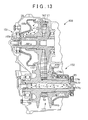
- FIG. 13 is a sectional of the continuously variable transmission according to the second example embodiment of the invention when the hydraulic fluid is drained from the primary pulley;
- FIG. 14 is a sectional view of a continuously variable transmission according to a third example embodiment of the invention.
- FIG. 15 is a partial enlarged sectional view of a portion of the continuously variable transmission shown in FIG. 14 ;
- FIG. 16A is a sectional view taken along section E-E in FIG. 15 ;
- FIG. 16B is a sectional view taken along section F-F in FIG. 15 ;
- FIG. 17 is a sectional view of the continuously variable transmission according to the third example embodiment of the invention.
- FIG. 18 is a sectional view of the continuously variable transmission according to the third example embodiment of the invention when hydraulic fluid is drained from the primary pulley;
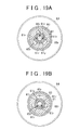
- FIG. 19A is a sectional view of the continuously variable transmission according to a modified example of the first example embodiment of the invention when three driving-side communicating fluid passages are communicated with three drive shaft internal fluid passages;
- FIG. 19B is a sectional view of the continuously variable transmission according to the modified example of the first example embodiment of the invention when two driving-side communicating fluid passages are communicated with two drive shaft internal fluid passages.
- FIG. 1 is a skeleton view of a vehicle provided with a continuously variable transmission according to a first example embodiment of the invention.
- FIG. 2 is a sectional view of the continuously variable transmission
- FIG. 3 is a partial enlarged sectional view of one portion of the continuously variable transmission shown in FIG. 2 .
- FIG. 4A is a sectional view taken along section A-A in FIG. 3
- FIG. 4B is a sectional view taken along section B-B in FIG. 3 .
- FIG. 5 is a partial enlarged sectional view of another portion of the continuously variable transmission shown in FIG. 2 .
- a vehicle according to the first example embodiment is configured as a front-wheel-drive vehicle (i.e., FF: Front engine, Front drive) and is provided with an engine 2 .
- the engine 2 is a transverse-mounted gasoline engine, but the engine 2 is not limited to this. That is, the engine 2 may also be an internal combustion engine that uses a gas fuel or liquid such as gas oil, LPG, hydrogen, or bio-fuel or the like.
- the arrangement of the engine 2 is also not limited. That is, it may be longitudinal mounted or transverse mounted, etc.
- the configuration of the engine also not limited. That is, the engine 2 may be an in-line engine, a horizontally opposed engine, or a V-type engine or the like. Further, the number of cylinders of the engine 2 is also not limited.
- the vehicle 1 includes the engine 2 described above, a transaxle 3 that is arranged to the side of the engine 2 and coupled to a crankshaft 2 a of the engine 2 , an ECU (electronic control unit) 4 that controls the engine 2 and the transaxle 3 , and a hydraulic fluid supply apparatus 5 .
- ECU electronic control unit
- the transaxle 3 includes a torque converter 6 that is coupled to the crankshaft 2 a , a forward-reverse switching mechanism 7 that is coupled to the torque converter 6 via an input shaft 3 n , a continuously variably transmission (CVT) 8 that is coupled to the forward-reverse switching mechanism 7 , a counter drive gear 9 that is coupled to the continuously variable transmission 8 , a counter driven gear 11 that is in mesh with the counter driven gear 9 , and an intermediate shaft 12 that supports the counter driven gear 11 .
- CVT continuously variably transmission
- the transaxle 3 also includes a final drive gear 13 that is supported by the intermediate shaft 12 , a ring gear 14 that is in mesh with the final drive gear 13 , a differential 15 that is coupled to the ring gear 14 , a transaxle housing 16 that houses these constituent elements, and a transaxle case 17 , and a transaxle rear cover 18 .
- the differential 15 is coupled to left and right front drive shafts 21 , which are in turn coupled to left and right front wheels, respectively.
- the torque converter 6 includes a drive plate 32 , a front cover 33 that is fixed to the crankshaft 2 a of the engine 2 via this drive plate 32 , a pump impeller 34 that is mounted to the front cover 33 , and a rotatable turbine runner 35 that is fixed to the input shaft 3 n which extends along generally the same axis as the crankshaft 2 a and is arranged facing the pump impeller 34 .
- the torque converter 6 also includes a stator 37 that is set to be able to rotate in only one direction by a one-way clutch 36 , a damper mechanism, and a lockup clutch 39 that is mounted to the damper mechanism 38 .
- a hollow shaft 31 is fixed to the stator 37 via the one-way clutch 36 , and the input shaft 3 n is inserted through this hollow shaft 31 .
- the stator 37 is designed such that when the difference between the rotation speed of the pump impeller 34 and the rotation speed of the turbine runner 35 is large, the flow of hydraulic fluid changes directions so that it helps the pump impeller 34 rotate.
- the torque converter 6 functions as a torque multiplier when the difference between the rotation speed of the pump impeller 34 and the rotation speed of the turbine runner 35 is large, and functions as a fluid coupling when that difference is small.
- the lockup clutch 39 activates so that power transmitted from the engine 2 to the front cover 33 is transmitted directly to the input shaft 3 n . Also, any fluctuation in the power transmitted from the front cover 33 to the input shaft 3 n is absorbed by the damper mechanism 38 .
- the forward-reverse switching mechanism 7 includes a double pinion planetary gear set 41 .
- This double pinion planetary gear set 41 includes a sun gear 42 that is mounted to the end portion on the continuously variable transmission 8 side of the input shaft 3 n , a ring gear 43 that is concentrically arranged on the outer peripheral side of the sun gear 42 , a plurality of pinions 44 that are in mesh with the sun gear 42 , a plurality of pinions 45 that are in mesh with both the ring gear 43 and the pinions 44 , and a carrier 46 that pivotally supports the pinions 44 and 45 and retains those pinions 44 and 45 so that they are able to revolve together around the sun gear 42 .
- the carrier 46 of the forward-reverse switching mechanism 7 is fixed to the continuously variable transmission 8 .
- the power transmitting path between the carrier 46 and the input shaft 3 n is able to be established or interrupted using a forward clutch CR.
- the forward-reverse switching mechanism 7 has a reverse brake BR that controls whether the ring gear 43 rotates or is held stationary.
- the continuously variable transmission 8 includes a primary pulley 51 , a secondary pulley 52 , and a drive belt 53 .
- the primary pulley 51 is formed with a so-called double piston and includes a drive shaft 61 , a driving-side fixed sheave 62 , a driving-side movable sheave 63 , a driving-side cylinder member 64 , a partition wall member 65 , and a pressing member 66 .
- the drive shaft 61 has a drive shaft internal fluid passage 61 y that is open at one end portion in the axial direction.
- a seal member 18 s provided on the transaxle rear cover 18 is inserted into the open portion 61 k .
- drive shaft internal fluid passages 61 r that open at the outer peripheral surface and are communicated with the drive shaft internal fluid passage 61 y are formed in three equidistant locations on the circumference of the drive shaft 61 , as shown in FIG. 4A .
- a hydraulic fluid supply passage, not shown, that is open at the outer peripheral surface and is communicated with the drive shaft internal fluid passage 61 y is also formed in the drive shaft 61 . Hydraulic fluid is supplied from the fluid supply apparatus 5 into the drive shaft internal fluid passage 61 y via this hydraulic fluid supply passage.
- the driving-side fixed sheave 62 is integrally formed with the drive shaft 61 at the other end portion of the drive shaft 61 in the axial direction. Also, ball spline grooves 61 m are formed in three equidistant locations on the circumference of the outer peripheral portion of the drive shaft 61 , as shown in FIG. 4B .
- the drive shaft 61 is rotatably supported by a bearing 24 provided on the transaxle case 17 and a bearing 23 provided on the transaxle rear cover 18 , both of which are shown in FIG. 1 , and coupled to the carrier 46 of the forward-reverse switching mechanism 7 , such that power is input to the drive shaft 61 from the forward-reverse switching mechanism 7 .
- the driving-side fixed sheave 62 has a belt squeezing portion 62 b and a cylindrical portion 62 e that forms part of the drive shaft 61 , as shown in FIG. 3 .
- the driving-side fixed sheave 62 is arranged facing the driving-side movable sheave 63 in the axial direction.
- An annular pulley groove 67 that has a generally V-shaped cross-section that the drive belt 53 winds around is partially defined by a side portion 62 s of the belt squeezing portion 62 b that faces the driving-side movable sheave 63 .
- This annular pulley groove 67 is supported by the bearing 24 shown in FIG. 1 at the cylindrical portion 62 e.
- the driving-side movable sheave 63 includes a belt squeezing portion 63 b , and an inner cylinder portion 63 n and an outer cylinder portion 63 g that are formed protruding to the side opposite the pulley groove 67 .
- the driving-side movable sheave 63 is arranged facing the driving-side fixed sheave 62 in the axial direction.
- the pulley groove 67 described above is partially defined by a side portion 63 s of the belt squeezing portion 63 b that faces the driving-side fixed sheave 62 .
- the drive belt 53 is sandwiched between this side portion 63 s and the side portion 62 s of the driving-side fixed sheave 62 by a predetermined pressure.
- Ball spline grooves 63 m are formed in three equidistant locations on the circumference of the inner cylinder portion 63 n , as shown in FIG. 4B . Also, ball splines 62 p are interposed between these ball spline grooves 63 m and the ball spline grooves 61 m of the drive shaft 61 , as shown in FIG. 3 , such that the driving-side movable sheave 63 moves smoothly in the axial direction, as well as rotates together with the drive shaft 61 .
- the driving-side cylinder member 64 has a disc-shaped side portion 64 s and a cylindrical portion 64 e formed protruding from the side portion 64 s toward the driving-side movable sheave 63 side.
- a through-hole 64 k is formed in the side portion 64 s .
- the drive shaft 61 is press-fitted into this through-hole 64 k , and the driving-side cylinder member 64 is fixed to the drive shaft 61 such that it rotates together with the drive shaft 61 .
- the cylindrical portion 64 e defines an annular driving-side cylinder 64 c to which hydraulic fluid is supplied by housing part of an outer cylinder portion 63 g of the driving-side movable sheave 63 and covering the side portion 63 f of the driving-side movable sheave 63 on the outer cylinder portion 63 g side.
- the partition wall member 65 has a disc-shaped side portion 65 s , a cylindrical portion 65 e that is formed protruding from the side portion 65 s toward the driving-side movable sheave 63 side, and a flange portion 65 f formed extending radially from the end portion of the cylindrical portion 65 e .
- a through-hole 65 k is formed in this side portion 65 s , and the drive shaft 61 is press-fitted into this through-hole 65 k .
- the partition wall member 65 is fixed to the drive shaft 61 , with the side portion 65 s closely contacting the side portion 64 s of the driving-side cylinder member 64 , such that the partition wall member 65 rotates together with the drive shaft 61 and the driving-side cylinder member 64 .
- driving-side communicating fluid passages 65 r that are communicated with the drive shaft internal fluid passages 61 r of the drive shaft 61 are formed in three equidistant locations on the circumference of the side portion 65 s , as shown in FIG. 4A .
- the inner cylinder portion 63 n of the driving-side movable sheave 63 is housed inside the cylindrical portion 65 e.
- a seal ring 65 g is fitted around the outer periphery of the flange portion 65 f such that when the driving-side movable sheave 63 moves, a liquid-tight seal is maintained between the inner peripheral surface of the outer cylinder portion 63 g of the driving-side movable sheave 63 and the outer peripheral surface of the flange portion 65 f.
- An annular sheave-side cylinder 65 c is defined by the surface of this partition wall member 65 on the driving-side movable sheave 63 side, the surface of the driving-side movable sheave 63 on the partition wall member 65 side, and the outer peripheral surface of the drive shaft 61 . Hydraulic fluid inside the drive shaft internal fluid passage 61 y is supplied into this sheave-side cylinder 65 c from the drive shaft internal fluid passages 61 r and the driving-side communicating passages 65 r.
- the pressing member 66 is formed in a disc shape with a through-hole 66 k that extends in the axial direction formed in it.
- the cylindrical portion 65 e of the partition wall member 65 is inserted into this through-hole 66 k , such that the pressing member 66 rotates together with the partition wall member 65 .
- the pressing member 66 is slidably supported by the cylindrical portion 65 e of the partition wall member 65 and the cylindrical portion 64 e of the driving-side cylinder member 64 , and pushes the outer cylinder portion 63 g of the driving-side movable sheave 63 .
- a seal ring 66 g is fitted on the outer periphery of the pressing member 66
- a seal ring 66 n is fitted on the inner periphery of the pressing member 66 , so that when the pressing member 66 moves, a liquid-tight seal is maintained between the outer peripheral surface of the cylindrical portion 65 e of the partition wall member 65 and the inner peripheral surface of the partition wall member 65 .
- An annular member-side air cylinder 66 e is defined by the surface of this pressing member 66 on the partition wall member 65 side, the surface of the partition wall member 65 on the pressing member 66 side, and the inner peripheral surface of the outer cylinder portion 63 g of the driving-side movable sheave 63 .
- a through-hole 63 k is formed in the end portion of the outer cylindrical portion 63 g of the driving-side movable sheave 63 , such that air in the member-side air cylinder 66 e can be discharged to the outside and outside air can be drawn into the member-side air cylinder 66 e .
- air pressure will not build up inside the member-side air cylinder 66 e so the sliding of the pressing member 66 will not be impeded.
- annular member-side hydraulic cylinder 66 o is defined by the surface of the pressing member 66 on the driving-side cylinder member 64 side, the surface of the driving-side cylinder member 64 on the pressing member 66 side, and the outer peripheral surface of the cylindrical portion 65 e of the partition wall member 65 .
- Hydraulic fluid in the drive shaft internal fluid passage 61 y is supplied to this member-side hydraulic cylinder 66 o from the drive shaft internal fluid passages 61 r and the driving-side communicating fluid passages 65 r .
- the member-side hydraulic cylinder 66 o and the member-side air cylinder 66 e each form a member-side cylinder of the invention.
- the secondary pulley 52 is formed with a so-called single piston and includes a driven shaft 71 that is parallel to the drive shaft 61 , a driven-side fixed sheave 72 , a driven-side movable sheave 73 , a driven-side cylinder member 74 , and a cover member 75 , as shown in FIGS. 2 and 5 .
- the driven shaft 71 has a driven shaft internal fluid passage 71 y that is open at one end portion in the axial direction.
- a seal member 18 j provided on the transaxle rear cover 18 is inserted into the open portion 71 k .
- driven shaft internal fluid passages 71 r that are open at the outer peripheral surface and communicated with the driven shaft internal fluid passage 71 y are formed in three equidistant locations on the circumference of the driven shaft 71 , just like the drive shaft 61 .
- a fluid supply passage, not shown, that is open at the outer peripheral surface and is communicated with the driven shaft internal fluid passage 71 y is also formed in the driven shaft 71 . Hydraulic fluid is supplied from the fluid supply apparatus 5 to the driven shaft internal fluid passage 71 y via this hydraulic supply passage.
- the driven-side fixed sheave 72 is integrally formed in the driven shaft 71 at the open portion 71 k of the driven shaft 71 .
- ball spline grooves 71 m are formed in three equidistant locations on the circumference of the outer peripheral portion of the driven shaft 71 , just as with the drive shaft 61 .
- the driven shaft 71 is rotatably supported by a bearing 25 provided on the transaxle case 17 , a bearing 26 provided on the transaxle rear cover 18 , and a bearing 27 provided on the transaxle housing 16 , all of which are shown in FIG. 1 , such that the power of the drive shaft 61 is transmitted to the driven shaft 71 via the drive belt 53 .
- the driven-side fixed sheave 72 has a belt squeezing portion 72 b just like the driving-side fixed sheave 62 , and is arranged facing the driven-side movable sheave 73 in the axial direction.
- An annular pulley groove 77 that has a generally V-shaped cross-section that the drive belt 53 winds around is partially defined by a side portion 72 s of the belt squeezing portion 72 b that faces the driven-side movable sheave 73 .
- the driven-side movable sheave 73 includes a belt squeezing portion 73 b , and an inner cylinder portion 73 n and an outer cylinder portion 73 g that are formed protruding to the side opposite the pulley groove 77 , just like the driving-side movable sheave 63 .
- the driven-side movable sheave 73 is arranged facing the driven-side fixed sheave 72 in the axial direction.
- the pulley groove 77 described above is partially defined by a side portion 73 s of the belt squeezing portion 73 b that faces the driven-side fixed sheave 72 .
- the drive belt 53 is sandwiched between this side portion 73 s and the side portion 72 s of the driven-side fixed sheave 72 by a predetermined pressure.
- Ball spline grooves 73 m are formed in three equidistant locations on the circumference of the inner cylinder portion 73 n , just like the driving-side movable sheave 63 . Also, ball splines 72 p are interposed between these ball spline grooves 73 m and the ball spline grooves 71 m of the driven shaft 71 , as shown in FIG. 3 , such that the driven-side movable sheave 73 moves smoothly in the axial direction, as well as rotates together with the driven shaft 71 .
- a coil spring 73 p surrounds the outer periphery of the inner cylinder portion 73 n and is interposed between the driven-side movable sheave 73 and the driven-side cylinder member 74 .
- This coil spring 73 p applies urging force that pushes the driven-side movable sheave 73 toward the driven-side fixed sheave 72 side.
- the driven-side cylinder member 74 has a disc-shaped side portion 74 s , a cylindrical portion 74 e formed protruding from the side portion 74 s toward the driven-side movable sheave 73 side, and a flange portion 74 f that extends radially outward from the cylindrical portion 74 e.
- a through-hole 74 k is formed in the side portion 74 s .
- the driven shaft 71 is press-fitted into this through-hole 74 k , and the driven-side cylinder member 74 is fixed to the driven shaft 71 such that it rotates together with the driven shaft 71 .
- the cylindrical portion 74 e houses the coil spring 73 p and part of the inner cylinder portion 73 n of the driven-side movable sheave 73 .
- a seal ring 74 g is fitted around the outer periphery of the flange portion 74 f such that when the driven-side movable sheave 73 moves, a liquid-tight seal is maintained between the inner peripheral surface of the outer cylinder portion 73 g of the driven-side movable sheave 73 and the outer peripheral surface of the flange portion 74 f.
- An annular driven-side cylinder 74 c is defined by the surface of the driven-side cylinder member 74 on the driven-side movable sheave 73 side, the surface of the driven-side movable sheave 73 on the driven-side cylinder member 74 side, and the outer peripheral surface of the driven shaft 71 .
- Driven-side communicating fluid passages 74 r that communicate the driven shaft internal fluid passages 71 r of the driven shaft 71 with the driven-side cylinder 74 c are formed in equidistant locations on the circumference of the driven-side cylinder member 74 , just like the driving-side communicating fluid passages 65 r of the partition wall member 65 . Hydraulic fluid inside the driven shaft internal fluid passage 71 y is supplied to this driven-side cylinder 74 c from the driven shaft internal fluid passages 71 r and the driven-side communicating passages 74 r.
- the cover member 75 has a disc-shaped side portion 75 s and a cylindrical portion 75 e formed protruding toward the driven-side movable sheave 73 side from the side portion 75 s .
- a through-hole 75 k is formed in the side portion 75 s , and the driven shaft 71 is press-fitted into this through-hole 75 k .
- the cover member 75 is fixed to the driven shaft 71 , with the side portion 75 s closely contacting the side portion 74 s of the driven-side cylinder member 74 , such that the cover member 75 rotates together with the driven shaft 71 and the driven-side cylinder member 74 .
- the drive belt 53 is formed of an endless belt that has many metal pieces and a plurality of steel rings to transmit a large amount of power.
- This drive belt 53 is wound around the pulley groove 67 of the primary pulley 51 and the pulley groove 77 of the secondary pulley 52 .
- Power input from the torque converter 6 to the primary pulley 51 via the forward-reverse switching mechanism 7 and the drive shaft 61 is output from the primary pulley 51 to the driven shaft 71 via the secondary pulley 52 at a predetermined speed ratio.
- This output power is transmitted to the differential 15 via the counter drive gear 9 that is spline-coupled to the outer peripheral portion of this driven shaft 71 , as shown in FIG. 1 .
- the differential 15 is provided with a hollow differential case 15 a .
- This differential case 15 a is rotatably supported by a bearing 28 provided on the transaxle case 17 and a bearing 29 provided on the transaxle housing 16 .
- the ring gear 14 is fixed to an outer peripheral portion of the differential case 15 a .
- a pinion shaft 15 p is supported in the differential case 15 a , and a pair of pinions 15 g are rotatably supported on the pinion shaft 15 p.
- This pair of pinions 15 g are in mesh with a pair of side gears 15 s , one of which is connected to a left front drive shaft 21 and the other of which is connected to a right front drive shaft 21 .
- the right front drive shaft 21 is connected to a left front wheel 22 and the right front drive shaft 21 is connected to a right front wheel 22 .
- the ECU 4 includes a CPU (Central Processing Unit), ROM (Read Only Memory), RAM (Random Access Memory) that temporarily stores data, EEPROM (Electronically Erasable and Programmable Read Only Memory) which is electrically rewritable non-volatile memory, an input interface circuit that includes an A/D converter and a buffer and the like, and an output interface circuit that includes drive circuit and the like.
- CPU Central Processing Unit
- ROM Read Only Memory
- RAM Random Access Memory
- EEPROM Electrically Erasable and Programmable Read Only Memory
- Various sensors that detect the operating state of the engine 2 are connected to the input interface circuit of the ECU 4 . Information output from these sensors is then read by the ECU 4 via the input interface circuit. The ECU 4 then controls various parts of the vehicle 1 , such as the engine 2 and the transaxle 3 , based on this information as well as information such as the data stored in the ROM.
- the hydraulic fluid supply apparatus 5 includes an oil pan 81 that collects hydraulic fluid, an oil strainer 82 through which the hydraulic fluid in the oil pan 81 is drawn up, a fluid passage portion 83 that has a passage for supplying hydraulic fluid, an oil pump 84 , a primary regulator valve 85 , a primary shift valve 86 , and a secondary shift valve 87 .
- the primary regulator valve 85 is formed of a regulator valve that regulates the pressure, for example. This primary regulator valve 85 regulates the line pressure generated by the oil pump 84 to a predetermined pressure.
- the primary regulator valve 85 is connected to a solenoid valve, not shown, controlled by the ECU 4 , and is controlled by signal pressure sent from that solenoid valve.
- the primary shift valve 86 is formed of a regulator valve that regulates pressure, just like the primary regulator valve 85 . This primary shift valve 86 supplies shift pressure to execute a shift to the primary pulley 51 . Also, the primary shift valve 86 has a drain 86 d . Hydraulic fluid discharged from the primary pulley 51 is discharged to the fluid passage portion 83 via this drain 86 d.
- the secondary shift valve 87 is also formed of a regulator valve that regulates pressure, just like the primary shift valve 86 .
- This secondary shift valve 87 supplies shift pressure to execute a shift to the secondary pulley 52 .
- the secondary shift valve 87 has a drain 87 d . Hydraulic fluid discharged from the secondary pulley 52 is discharged to the fluid passage portion 83 via this drain 87 d , and circulated into the oil pan 81 .
- Hydraulic fluid in the oil pan 81 is drawn up by the oil pump 84 and flows into the fluid passage portion 83 , where the hydraulic pressure is regulated by the primary regulator valve 85 and the primary shift valve 86 .
- the hydraulic fluid continues to flow through the fluid passage portion 83 and is supplied to the primary pulley 51 .
- the hydraulic fluid also flows through the fluid passage portion 83 and the hydraulic pressure of that hydraulic fluid is regulated by the secondary shift valve 87 .
- the hydraulic fluid then continues to flow through the fluid passage portion 83 and is supplied to the secondary pulley 52 .
- the hydraulic fluid that has been supplied to the primary pulley 51 and used as the hydraulic power medium then flows through the fluid passage portion 83 and is circulated to the oil pan 81 via the drain 86 d of the primary shift valve 86 .
- the hydraulic fluid that has been supplied to the secondary pulley 52 and used as the hydraulic power medium then flows through the fluid passage portion 83 and is circulated to the oil pan 81 via the drain 87 d of the secondary shift valve 87 .
- the primary regulator valve 85 , the primary shift valve 86 , and the secondary shift valve 87 are all connected to the ECU 4 , as indicated by the dotted lines.
- the ECU 4 controls these valves to supply hydraulic fluid at a predetermined hydraulic pressure to the primary pulley 51 and the secondary pulley 52 according to the operation of the driver of the vehicle 1 and the operating state of the vehicle 1 .
- the oil pump 84 is formed of a pump that draws up hydraulic fluid and discharges it, such as a gear pump or a trochoid pump or the like.
- the oil pump 84 includes a main body 84 a that is fixed to the transaxle case 17 and a rotor 84 c that is connected to the pump impeller 34 of the torque converter 6 via a hub 84 b .
- the hub 84 b is spline-engaged with the hollow shaft 31 of the torque converter 6 . Accordingly, the power from the engine 2 is transmitted to the hollow shaft 31 via the pump impeller 34 , and the rotor 84 c rotates together with the hollow shaft 31 , thereby driving the oil pump 84 .
- This oil pump 84 may also has a structure other than the structure shown in FIG. 1 .
- it may also be formed by hydraulic fluid supplying means such as a trochoid pump that is connected to the crankshaft 2 a either directly or indirectly via a transmitting member such as a chain.
- FIG. 6 is a sectional view of the continuously variable transmission according to the first example embodiment when hydraulic fluid is supplied to the primary pulley.
- FIG. 7 is a sectional view of the continuously variable transmission according to the first example embodiment when hydraulic fluid is drained from the primary pulley.
- the drive plate 32 of the torque converter 6 , the front cover 33 , and the pump impeller 34 rotate via the crankshaft 2 a , as shown in FIG. 1 .
- the circulation flowrate of the hydraulic fluid generated inside the torque converter 6 at this time drags the turbine runner 5 so that it rotates, at which time the input shaft 3 n also rotates.
- the sun gear 42 of the planetary gear set 41 of the forward-reverse switching mechanism 7 rotates, causing the pinions 44 and 45 , and thus the carrier 46 , to also rotate.
- the ECU 4 appropriately switches to forward or reverse by appropriately controlling the forward clutch CR and the reverse brake, i.e., applying or releasing the forward clutch CR and applying or releasing the reverse brake BR, according to the operation by the driver and the operating state of the vehicle 1 .
- the rotation of the carrier 46 is transmitted to the primary pulley 51 via the drive shaft 61 , and when the primary pulley 51 rotates, the secondary pulley 52 rotates via the drive belt 53 such that the driven shaft 71 also rotates.
- the counter drive gear 9 rotates, such that the counter driven gear 11 and the final drive gear 13 also rotate, which causes the ring gear 14 to rotate. This activates the differential 15 such that the front drive shafts 21 rotate, ultimately transmitting the power to the front wheels 22 .
- the pump impeller 34 rotates, it causes the hollow shaft 31 as well as the rotor 84 c of the oil pump 34 to rotate, such that hydraulic fluid inside the oil pan 81 is drawn up through the inlet of the oil strainer 82 .
- the hydraulic fluid After being strained by the oil strainer 82 to remove impurities, the hydraulic fluid then flows into the fluid passage portion 83 and into the oil pump 84 .
- the hydraulic fluid is then discharged from the oil pump 84 at a pressure referred to as line pressure and is supplied at this line pressure to the primary regulator valve 85 , the primary shift valve 86 , and the secondary shift valve 87 .
- the ECU 4 controls the primary regulator valve 85 , the primary shift valve 86 , and the secondary shift valve 87 according to an operation of the driver of the vehicle 1 and the operating state of the vehicle 1 , while hydraulic fluid at line pressure is supplied to those valves.
- a predetermined shift pressure that has been regulated is supplied to the sheave-side cylinder 65 c and the member-side hydraulic cylinder 66 o of the primary pulley 51 and the driven-side cylinder 74 c of the secondary pulley 52 , such that the power of the drive shaft 61 is output to the driven shaft 71 at a speed ratio appropriate for the operating state of the vehicle 1 .
- the ECU 4 performs control to establish a high speed ratio in response to the operation of an accelerator pedal, not shown. That is, the hydraulic pressure is increased to a predetermined shift pressure by the primary shift valve 86 .
- the hydraulic fluid at this increased hydraulic pressure is supplied to the drive shaft internal fluid passage 61 y , as shown in FIG. 6 , via the fluid passage portion 83 , passes through the drive shaft internal fluid passages 61 r and the driving-side communicating fluid passages 65 r , and is supplied to the sheave-side cylinder 65 c and the member-side hydraulic cylinder 66 o.
- the hydraulic pressure inside the sheave-side cylinder 65 c increases, such that hydraulic pressure is applied to the side portion 63 f of the driving-side movable sheave 63 inside the sheave-side cylinder 65 c .
- pressure Fa is applied in the direction of the driving-side fixed sheave 62 to the driving-side movable sheave 63 .
- the hydraulic pressure in the member-side hydraulic cylinder 66 o increases the hydraulic pressure applied to the pressing member 66 , such that pressure Pb is applied in the direction of the driving-side fixed sheave 62 to the pressing member 66 .
- the pressing member 66 in turn applies the pressure Fb in the direction of the driving-side fixed sheave 62 to the driving-side movable sheave 63 at the outer cylinder portion 63 g.
- the ECU 4 shown in FIG. 1 opens the drain 87 d of the secondary shift valve 87 and reduces the pressure in the driven-side cylinder 74 c shown in FIG. 6 .
- the hydraulic fluid in the driven-side cylinder 74 c drains into the fluid passage portion 83 of the hydraulic fluid supply apparatus 5 through the driven-side communicating fluid passages 74 r and the driven shaft internal fluid passages 71 r and 71 y .
- the pressures Fa and Fb of the driving-side movable sheave 63 cause the driven-side movable sheave 73 to move away from the driven-side fixed sheave 72 such that the drive belt 53 slides radially inward and the belt radius on the driven side decreases.
- the speed ratio represented by the driven-side belt radius divided by the driving-side belt radius gradually and continuously (i.e., steplessly) becomes a high speed ratio, thereby accelerating the vehicle 1 .
- the ECU 4 performs control to establish a low speed ratio. That is, the secondary shift valve 87 increases the pressure to a predetermined shift pressure, as shown in FIG. 7 .
- the hydraulic fluid at this increased pressure is supplied to the driven shaft internal fluid passage 71 y , as shown in FIG. 7 , via the fluid passage portion 83 , and then supplied to the driven-side cylinder 74 c through the driven shaft internal fluid passages 71 r and the driven-side communicating fluid passages 74 r .
- the pressure in the driven-side cylinder 74 c increases, which increases the pressure applied to the side portion 73 s of the driven-side movable sheave 73 in the driven-side cylinder 74 c , such that pressure Fc is applied in the direction of the driven-side fixed sheave 72 to the driven-side movable sheave 73 .
- This pressure Fc causes the driven-side movable sheave 73 to quickly move toward the driven-side fixed sheave 72 , thereby narrowing the pulley groove 77 such that the drive belt 53 slides radially outward and the belt radius on the driving side increases.
- the ECU 4 shown in FIG. 1 opens the drain 86 d of the primary shift valve 86 and reduces the pressure in the sheave-side cylinder 65 c and the member-side hydraulic cylinder 66 o .
- the hydraulic fluid in the sheave-side cylinder 65 c and the member-side hydraulic cylinder 66 o drains into the fluid passage portion 83 of the hydraulic fluid supply apparatus 5 through the driving-side communicating fluid passages 65 r and the drive shaft internal fluid passages 61 r and 61 y .
- the pressure Fc of the driven-side movable sheave 73 causes the driving-side movable sheave 63 to move away from the driving-side fixed sheave 62 such that the drive belt 53 slides radially inward and the belt radius on the driving side decreases.
- the speed ratio represented by the driven-side belt radius divided by the driving-side belt radius gradually and continuously (i.e., steplessly) becomes a low speed ratio, thereby decelerating the vehicle 1 .
- the continuously variable transmission 8 according to the first example embodiment is structured as described above, which enables the effects described below to be obtained.
- the continuously variable transmission 8 includes the primary pulley 51 that has the driving-side fixed sheave 62 that is fixed to the drive shaft 61 , the driving-side movable sheave 63 , and the driving-side cylinder member 64 that defines the driving-side cylinder 64 c .
- the continuously variable transmission 8 also includes the secondary pulley 52 that has the driven-side fixed sheave 72 that is fixed to the driven shaft 71 , the driven-side movable sheave 73 , and the driven-side cylinder member 74 that defines the driven-side cylinder 74 c .
- the continuously variable transmission 8 also includes the drive belt 53 .
- the driving-side cylinder member 64 is provided with a partition wall member 65 that defines the sheave-side cylinder 65 c , and a pressing member 66 that defines the member-side hydraulic cylinder 66 o and the member-side air cylinder 66 e , and pushes the driving-side movable sheave 63 in the axial direction using the hydraulic pressure in the member-side hydraulic cylinder 66 o .
- the drive shaft internal fluid passages 61 y and 61 r are formed in the drive shaft 61 , and the driving-side communicating fluid passages 65 r that communicate the sheave-side cylinder 65 c , the member-side hydraulic cylinder 66 o , and the drive shaft internal fluid passages 61 r together are formed in the partition wall member 65 .
- hydraulic fluid supplied into the drive shaft internal fluid passage 61 y is supplied to the sheave-side cylinder 65 c and the member-side hydraulic cylinder 66 o through the drive shaft internal fluid passages 61 r and the driving-side communicating fluid passages 65 r . Therefore, the structure is simpler than that of the related continuously variable transmission.
- the fluid passage extending at an angle from the outer periphery toward the inner periphery of the inner cylinder portion is formed using a drilling tool from between the inner cylinder portion and the outer cylinder portion of the driving-side movable sheave.
- the driving-side communicating fluid passages 65 c for supplying hydraulic fluid to the sheave-side cylinder 65 c and the member-side hydraulic cylinder 66 o are formed in the partition wall member 65 , as shown in FIGS. 3 and 4A , and thus provide a simple structure that is communicated with the drive shaft internal fluid passages 61 r.
- the continuously variable transmission according to the first example embodiment improves production efficiency by reducing the trouble that it takes to form the fluid passages compared with the related continuously variable transmission. That is, in the related continuously variable transmission, the drilling tool is set between the inner cylinder portion and the outer cylinder portion of the driving-side movable sheave and the fluid passage is formed at an angle from the outer periphery of the inner cylinder portion toward the inner periphery of the inner cylinder portion. However, in the continuously variable transmission according to the first example embodiment, it is not necessary to form this kind of fluid passage, so forming the fluid passage is less troublesome.
- the driving-side communicating fluid passages 65 r can be easily formed in the partition wall member 65 at the same time the through-hole 65 k is formed in the partition wall member 65 , in a single press-forming process using a hole-making machine such as a punch press.
- burrs formed in the through-hole 65 k and the driving-side communicating fluid passages 65 r can be removed at the same time in a single process. As a result, no special forming process is needed to form the driving-side communicating fluid passages 65 r , so forming the fluid passages is less troublesome.
- burrs in the driving-side communicating passages 65 r are exposed to the outside and therefore can be easily removed, which makes forming the fluid passages less troublesome.
- the hydraulic fluid supply apparatus 5 includes the primary regulator valve 85 that is connected to the oil pump 84 , the primary shift valve 86 that is connected to the primary regulator valve 85 , and the secondary shift valve 87 that is connected to the oil pump 84 , and the primary pulley pressure is controlled as the shift pressure and the secondary pulley pressure is controlled as the line pressure throughout all of the speed ranges.
- the hydraulic fluid supply apparatus may have other constituent elements.
- the hydraulic fluid supply apparatus may also be a so-called double pressure regulating type hydraulic fluid supply apparatus that includes a primary regulator valve that is connected to an oil pump, a primary shift valve that is connected to the primary regulator valve, and a secondary shift valve that is connected to the primary regulator valve.
- the primary pulley pressure in a speed range on the low speed ratio side, the primary pulley pressure may be controlled as the shift pressure and the secondary pulley pressure may be controlled as the line pressure
- the primary pulley pressure in a shift range on the high speed ratio side, the primary pulley pressure may be controlled as the line pressure and the secondary pulley pressure may be controlled as the shift pressure.
- the driving-side communicating fluid passages 65 r are formed in the primary pulley 51 and the driven-side communicating fluid passages 74 r are formed in the secondary pulley 52 .
- only the driving-side communicating fluid passages may be formed in the primary pulley or only the driven-side communicating fluid passages may be formed in the secondary pulley.
- FIG. 8 is a sectional view of a continuously variable transmission according to a second example embodiment of the invention
- FIG. 9 is a partial enlarged sectional view of a portion of the continuously variable transmission shown in FIG. 8
- FIG. 10A is a sectional view of the continuously variable transmission taken along section C-C in FIG. 9
- FIG. 10B is a sectional view taken along section D-D in FIG. 9
- FIG. 11 is a partial enlarged sectional view of a portion of the continuously variable transmission shown in FIG. 8 .
- the continuously variable transmission 108 according to this second example embodiment has the same structure as that of the continuously variable transmission 8 according to the first example embodiment described above, with the exception of the primary pulley 51 and the secondary pulley 52 in the first example embodiment. Therefore, like structures will be described using the same reference numerals used in the first example embodiment shown in FIGS. 1 to 7 , and only the differences from the first example embodiment will be described in detail.
- a vehicle 100 according to the second example embodiment is structured like the vehicle 1 in the first example embodiment, with the exception of the transaxle 103 .
- the transaxle 103 is similar to the transaxle 3 in the first example embodiment, with the exception of the continuously variable transmission 108 .
- the continuously variable transmission 108 includes a primary pulley 151 , a secondary pulley 152 , and the drive belt 53 .
- the primary pulley 151 is formed with a so-called single piston and includes a drive shaft 161 , a driving-side fixed sheave 162 , a driving-side movable sheave 163 , and a driving-side cylinder member 164 .
- the drive shaft 161 has a drive shaft internal fluid passage 161 y that is open at one end portion in the axial direction.
- a seal member 118 s provided on the transaxle rear cover 18 is inserted into the open portion 161 k .
- drive shaft internal fluid passages 161 r that open at the outer peripheral surface and are communicated with the drive shaft internal fluid passage 161 y are formed in three equidistant locations on the circumference of the drive shaft 161 , as shown in FIG. 10A .
- a hydraulic fluid supply passage, not shown, that is open at the outer peripheral surface and is communicated with the drive shaft internal fluid passage 161 y is also formed in the drive shaft 161 . Hydraulic fluid is supplied from the hydraulic fluid supply apparatus 5 into the drive shaft internal fluid passage 161 y via this hydraulic fluid supply passage.
- a driving-side fixed sheave 162 is integrally formed with the drive shaft 161 at the other end portion of the drive shaft 161 in the axial direction. Also, external spline teeth 161 s are formed on the outer peripheral portion of the drive shaft 161 , as shown in FIG. 10B .
- the drive shaft 161 is rotatably supported by the bearing 24 provided on the transaxle case 17 and the bearing 23 provided on the transaxle rear cover 18 , both of which are shown in FIG. 1 , and coupled to the carrier 46 of the forward-reverse switching mechanism 7 , such that power is input to the drive shaft 161 from the forward-reverse switching mechanism 7 .
- the driving-side fixed sheave 162 has a belt squeezing portion 162 b and a cylindrical portion 162 e that forms part of the drive shaft 161 , as shown in FIG. 9 .
- the driving-side fixed sheave 162 is arranged facing the driving-side movable sheave 163 in the axial direction.
- An annular pulley groove 167 that has a generally V-shaped cross-section that the drive belt 53 winds around is partially defined by a side portion 162 s of the belt squeezing portion 162 b that faces the driving-side movable sheave 163 .
- This annular pulley groove 167 is supported by the bearing 24 at the cylindrical portion 162 e.
- the driving-side movable sheave 163 includes a belt squeezing portion 163 b , and an inner cylinder portion 163 n and an outer cylinder portion 163 g that are formed protruding to the side opposite the pulley groove 167 .
- the driving-side movable sheave 163 is arranged facing the driving-side fixed sheave 162 in the axial direction.
- the pulley groove 167 described above is partially defined by a side portion 163 s of the belt squeezing portion 163 b that faces the driving-side fixed sheave 162 .
- the drive belt 53 is sandwiched between this side portion 163 s and the side portion 162 s of the driving-side fixed sheave 162 by a predetermined pressure.
- Internal spline teeth 163 u are formed on the inner cylinder portion 163 n , as shown in FIG. 10B . These inner spline teeth 163 u are spline-engaged with the outer spline teeth 161 s of the drive shaft 161 , such that the driving-side movable sheave 163 moves along the drive shaft 161 , as well as rotates together with the drive shaft 161 .
- the driving-side cylinder member 164 has a disc-shaped side portion 164 s and a cylindrical portion 164 e formed protruding from the side portion 164 s toward the driving-side movable sheave 163 side.
- a through-hole 164 k is formed in the side portion 164 s .
- the drive shaft 161 is press-fitted into this through-hole 164 k , and the driving-side cylinder member 164 is fixed to the drive shaft 161 such that it rotates together with the drive shaft 161 .
- the cylindrical portion 164 e defines an annular driving-side cylinder 164 c to which hydraulic fluid is supplied by housing part of an outer cylinder portion 163 g of the driving-side movable sheave 163 and covering the side portion 163 f of the driving-side movable sheave 163 on the outer cylinder portion 163 g side.
- driving-side communicating fluid passages 164 r that are communicated with the drive shaft internal fluid passages 161 r of the driving-side cylinder 164 c are formed in three equidistant locations on the circumference of the side portion 165 s , as shown in FIG. 10A .
- One end of each of these driving-side communicating fluid passages 164 r is closed off at the side surface of the bearing 23 so that hydraulic fluid does not leak out from those driving-side communicating fluid passages 164 r.
- the secondary pulley 152 is formed with a so-called single piston and includes a driven shaft 171 that is parallel to the drive shaft 161 , a driven-side fixed sheave 172 , a driven-side movable sheave 173 , a driven-side cylinder member 174 , and a cover member 175 , as shown in FIGS. 8 and 11 .
- the driven shaft 171 has a driven shaft internal fluid passage 171 y that is open at one end portion in the axial direction.
- a seal member 118 j provided on the transaxle rear cover 18 is inserted into the open portion 171 k .
- driven shaft internal fluid passages 171 r that are open at the outer peripheral surface and communicated with the driven shaft internal fluid passage 171 y are formed in three equidistant locations on the circumference of the driven shaft 171 , just like the drive shaft 161 .
- a hydraulic fluid supply passage, not shown, that is open at the outer peripheral surface and is communicated with the driven shaft internal fluid passage 171 y is also formed in the driven shaft 171 . Hydraulic fluid is supplied from the hydraulic fluid supply apparatus 5 to the driven shaft internal fluid passage 171 y via this hydraulic fluid supply passage.
- the driven-side fixed sheave 172 is integrally formed in the driven shaft 171 near the open portion 171 k of the driven shaft 171 . Also, external spline teeth 171 s are formed on the outer peripheral portion of the driven shaft 171 , just like the drive shaft 161 .
- the driven shaft 171 is rotatably supported by the bearing 25 provided on the transaxle case 17 , the bearing 26 provided on the transaxle rear cover 18 , and the bearing 27 provided on the transaxle housing 16 , all of which are shown in FIG. 1 , such that power of the drive shaft 161 is transmitted to the driven shaft 171 via the drive belt 53 .
- the driven-side fixed sheave 172 has a belt squeezing portion 172 b just like the driving-side fixed sheave 162 , and is arranged facing the driven-side movable sheave 173 in the axial direction.
- An annular pulley groove 177 that has a generally V-shaped cross-section that the drive belt 53 winds around is partially defined by a side portion 172 s of the belt squeezing portion 172 b that faces the driven-side movable sheave 173 .
- the driven-side movable sheave 173 includes a belt squeezing portion 173 b , and an inner cylinder portion 173 n and an outer cylinder portion 173 g that are formed protruding to the side opposite the pulley groove 177 , just like the driving-side movable sheave 163 .
- the driven-side movable sheave 173 is arranged facing the driven-side fixed sheave 172 in the axial direction.
- the pulley groove 177 described above is partially defined by a side portion 173 s of the belt squeezing portion 173 b that faces the driven-side fixed sheave 172 .
- the drive belt 53 is sandwiched between this side portion 173 s and the side portion 172 s of the driven-side fixed sheave 172 by a predetermined pressure.
- Internal spline teeth 173 u are formed on the inner cylinder portion 173 n , just like the driving-side movable sheave 163 . These inner spline teeth 173 u are spline-engaged with the outer spline teeth 171 s of the driven shaft 171 , such that the driven-side movable sheave 173 moves along the driven shaft 171 , as well as rotates together with the driven shaft 171 .
- a coil spring 173 p surrounds the outer periphery of the inner cylinder portion 173 n and is interposed between the driven-side movable sheave 173 and the driven-side cylinder member 174 .
- This coil spring 173 p applies urging force that pushes the driven-side movable sheave 173 toward the driven-side fixed sheave 172 side.
- the driven-side cylinder member 174 has a disc-shaped side portion 174 s , a cylindrical portion 174 e formed protruding from the side portion 174 s toward the driven-side movable sheave 173 side, and a flange portion 174 f that extends radially outward from the cylindrical portion 174 e.
- a through-hole 174 k is formed in the side portion 174 s .
- the driven shaft 171 is press-fitted into this through-hole 174 k , and the driven-side cylinder member 174 is fixed to the driven shaft 171 such that it rotates together with the driven shaft 171 .
- the cylindrical portion 174 e houses the coil spring 173 p and part of the inner cylinder portion 173 n of the driven-side movable sheave 173 .
- a seal ring 174 g is fitted around the outer periphery of the flange portion 174 f such that when the driven-side movable sheave 173 moves, a liquid-tight seal is maintained between the inner peripheral surface of the outer cylinder portion 173 g of the driven-side movable sheave 173 and the outer peripheral surface of the flange portion 174 f.
- An annular driven-side cylinder 174 c is defined by the surface of the driven-side cylinder member 174 on the driven-side movable sheave 173 side and the surface of the driven-side movable sheave 173 on the driven-side cylinder member 174 side.
- Driven-side communicating fluid passages 174 r that communicate the driven shaft internal fluid passages 171 r of the driven shaft 171 with the driven-side cylinder 174 c are formed in equidistant locations on the circumference of the driven-side cylinder member 174 . Hydraulic fluid inside the driven shaft internal fluid passage 171 y is supplied to this driven-side cylinder 174 c from the driven shaft internal fluid passages 171 r and the driven-side communicating passages 174 r .
- each of these driven-side communicating fluid passages 174 r formed in the side portion 174 s of this driven-side cylinder member 174 is closed off at the side surface of the bearing 25 so that hydraulic fluid does not leak out from those driven-side communicating fluid passages 174 r.
- FIG. 12 is a sectional view of the continuously variable transmission according to the second example embodiment when the hydraulic fluid is supplied to the primary pulley
- FIG. 13 is a sectional of the continuously variable transmission according to the second example embodiment when the hydraulic fluid is drained from the primary pulley.
- the continuously variable transmission 108 according to the second example embodiment operates the same as the continuously variable transmission 108 according to the first example embodiment, with the exception of the operation of the primary pulley 151 and the secondary pulley 152 .
- the ECU 4 controls the primary regulator valve 85 , the primary shift valve 86 , and the secondary shift valve 87 shown in FIG. 1 according to the operation by the driver of the vehicle 100 and the operating state of the vehicle 100 , while hydraulic fluid at line pressure is supplied to those valves.
- hydraulic fluid at a predetermined shift pressure that has been regulated is supplied to the driving-side cylinder 164 c of the primary pulley 151 and the driven-side cylinder 174 c of the secondary cylinder 152 , such that the power of the drive shaft 161 is output to the driven shaft 171 at a speed ratio that is appropriate for the operating state of the vehicle 100 .
- the ECU 4 when the vehicle 100 is accelerated, the ECU 4 performs control to establish a high speed ratio in response to the operation of an accelerator pedal, not shown. That is, the hydraulic pressure is increased to a predetermined shift pressure by the primary shift valve 86 shown in FIG. 1 .
- the hydraulic fluid at this increased hydraulic pressure is supplied to the drive shaft internal fluid passage 161 y via the fluid passage portion 83 , after which it passes through the drive shaft internal fluid passages 161 r and the driving-side communicating fluid passages 164 r and is supplied to the driving-side cylinder 164 c .
- the hydraulic pressure inside the driving-side cylinder 164 c increases, such that hydraulic pressure is applied to the side portion 163 f of the driving-side movable sheave 163 inside the driving-side cylinder 164 c .
- pressure Fd is applied in the direction of the driving-side fixed sheave 162 to the driving-side movable sheave 163 .
- This pressure Fd causes the driving-side movable sheave 163 to move quickly toward the driving-side fixed sheave 162 , thereby narrowing the pulley groove 167 such that the drive belt 53 slides radially outward and the belt radius on the driving side increases.
- the ECU 4 shown in FIG. 1 opens the drain 87 d of the secondary shift valve 87 and reduces the pressure in the driven-side cylinder 174 c .
- the hydraulic fluid in the driven-side cylinder 174 c drains into the fluid passage portion 83 of the hydraulic fluid supply apparatus 5 through the driven-side communicating fluid passages 174 r and the driven shaft internal fluid passages 171 r and 171 y .
- the pressure Fd of the driving-side movable sheave 163 causes the driven-side movable sheave 173 to move away from the driven-side fixed sheave 172 such that the drive belt 53 slides radially inward and the belt radius on the driven side decreases.
- the speed ratio represented by the driven-side belt radius divided by the driving-side belt radius gradually and continuously (i.e., steplessly) becomes a high speed ratio, thereby accelerating the vehicle 100 .
- the ECU 4 performs control to establish a low speed ratio. That is, the secondary shift valve 87 increases the pressure to a predetermined shift pressure, as shown in FIG. 13 .
- the hydraulic fluid at this increased pressure is supplied to the driven shaft internal fluid passage 171 y via the fluid passage portion 83 , and then supplied to the driven-side cylinder 174 c through the driven shaft internal fluid passages 171 r and the driven-side communicating fluid passages 174 r .
- the pressure in the driven-side cylinder 174 c increases, which increases the pressure applied to the side portion 173 s of the driven-side movable sheave 173 in the driven-side cylinder 74 c , such that pressure Fd is applied in the direction of the driven-side fixed sheave 172 to the driven-side movable sheave 173 .
- This pressure Fd causes the driven-side movable sheave 173 to quickly move toward the driven-side fixed sheave 172 , thereby narrowing the pulley groove 177 such that the drive belt 53 slides radially outward and the belt radius on the driving side increases.
- the ECU 4 shown in FIG. 1 opens the drain 86 d of the primary shift valve 86 and reduces the pressure in the driving-side cylinder 164 c .
- the hydraulic fluid in the driving-side cylinder 164 c drains into the fluid passage portion 83 of the hydraulic fluid supply apparatus 5 through the driving-side communicating fluid passages 165 r and the drive shaft internal fluid passages 161 r and 161 y .
- the pressure Fd of the driven-side movable sheave 173 causes the driving-side movable sheave 163 to move away from the driving-side fixed sheave 162 such that the drive belt 53 slides radially inward and the belt radius on the driving side decreases.
- the speed ratio represented by the driven-side belt radius divided by the driving-side belt radius gradually and continuously (i.e., steplessly) becomes a low speed ratio, thereby decelerating the vehicle 100 .
- the continuously variable transmission 108 according to the second example embodiment is structured as described above, which enables the effects described below to be obtained. That is, the continuously variable transmission 108 according to the second example embodiment includes the primary pulley 151 that has the driving-side fixed sheave 62 that is fixed to the drive shaft 161 , the driving-side movable sheave 163 , and the driving-side cylinder member 164 that defines the driving-side cylinder 164 c.
- the continuously variable transmission 108 also includes the secondary pulley 52 that has the driven-side fixed sheave 172 that is fixed to the driven shaft 171 , the driven-side movable sheave 173 , and the driven-side cylinder member 174 that defines the driven-side cylinder 174 c .
- the continuously variable transmission 108 also includes the drive belt 53 .
- the drive shaft internal fluid passages 161 y and 161 r are formed in the drive shaft 161
- the driving-side communicating fluid passages 164 r that communicate the driving-side cylinder 164 c with the drive shaft internal fluid passages 161 r are formed in the driving-side cylinder member 164 .
- hydraulic fluid supplied into the drive shaft internal fluid passage 161 y is supplied to the driving-side cylinder 164 c through the drive shaft internal fluid passages 161 r and the driving-side communicating fluid passages 165 r . Therefore, the structure is simpler than that of the related continuously variable transmission. That is, in the related continuously variable transmission, the fluid passage extending at an angle from the outer periphery toward the inner periphery of the inner cylinder portion is formed using a drilling tool from between the inner cylinder portion and the outer cylinder portion of the driving-side movable sheave. However, in the continuously variable transmission according to the second example embodiment, it is not necessary to form this kind of fluid passage, so the structure is simpler.
- the driving-side communicating fluid passages 165 c for supplying hydraulic fluid to the driving-side cylinder 164 c are formed in the driving-side cylinder member 164 , as shown in FIGS. 9 and 10A , and thus provide a simple structure that is communicated with the drive shaft internal fluid passages 161 r.
- the continuously variable transmission according to the second example embodiment improves production efficiency by reducing the trouble that it takes to form the fluid passages compared with the related continuously variable transmission. That is, in the related continuously variable transmission, the drilling tool is set between the inner cylinder portion and the outer cylinder portion of the driving-side movable sheave and the fluid passage is formed at an angle from the outer periphery of the inner cylinder portion toward the inner periphery of the inner cylinder portion. However, in the continuously variable transmission according to the second example embodiment, it is not necessary to form this kind of fluid passage, so forming the fluid passage is less troublesome.
- the driving-side communicating fluid passages 165 r can be easily formed in the driving-side cylinder member 164 at the same time the through-hole 164 k is formed in the driving-side cylinder member 164 , in a single press-forming process using a hole-making machine such as a punch press.
- burrs formed in the through-hole 164 k and the driving-side communicating fluid passages 165 r can be removed at the same time in a single process. As a result, no special forming process is needed to form the driving-side communicating fluid passages 165 r , so forming the fluid passages is less troublesome.
- burrs in the driving-side communicating passages 165 r are exposed to the outside and therefore can be easily removed, which makes forming the fluid passages less troublesome.
- FIG. 14 is a sectional view of a continuously variable transmission according to a third example embodiment of the invention.
- FIG. 15 is a partial enlarged sectional view of a portion of the continuously variable transmission shown in FIG. 14 .
- FIG. 16A is a sectional view taken along section E-E in FIG. 15
- FIG. 16B is a sectional view taken along section F-F in FIG. 15 .
- the continuously variable transmission 208 according to this third example embodiment has the same structure as that of the continuously variable transmission 8 according to the first example embodiment described above, with the exception of the primary pulley 51 in the first example embodiment. Therefore, like structures will be described using the same reference numerals used in the first example embodiment shown in FIGS. 1 to 7 , and only the differences from the first example embodiment will be described in detail.
- a vehicle 200 according to the third example embodiment is structured like the vehicle 1 in the first example embodiment, with the exception of the transaxle 203 .
- the transaxle 203 is similar to the transaxle 3 in the first example embodiment, with the exception of the continuously variable transmission 208 .
- the continuously variable transmission 208 includes a primary pulley 251 , a secondary pulley 252 , and the drive belt 53 .
- the primary pulley 251 is formed with a so-called double piston and includes a drive shaft 261 , a driving-side fixed sheave 262 , a driving-side movable sheave 263 , a driving-side cylinder member 264 , a partition wall member 265 , and a pressing member 266 .
- the drive shaft 261 has a drive shaft internal fluid passage 261 y that is open at one end portion in the axial direction.
- a seal member 218 s provided on the transaxle rear cover 18 is inserted into the open portion 261 k.
- drive shaft internal fluid passages 261 r that open at the outer peripheral surface and are communicated with the drive shaft internal fluid passage 261 y are formed in three equidistant locations on the circumference of the drive shaft 261 , as shown in FIG. 16A .
- a hydraulic fluid supply passage not shown, that is open at the outer peripheral surface and is communicated with the drive shaft internal fluid passage 261 y is also formed in the drive shaft 261 . Hydraulic fluid is supplied from the hydraulic fluid supply apparatus 5 into the drive shaft internal fluid passage 261 y via this hydraulic fluid supply passage.
- a driving-side fixed sheave 262 is integrally formed with the drive shaft 261 at the other end portion of the drive shaft 261 in the axial direction. Also, ball spline grooves 261 m are formed in three equidistant locations on the circumference of the outer peripheral portion of the drive shaft 261 , as shown in FIG. 16B .
- the drive shaft 261 is rotatably supported by a bearing 24 provided on the transaxle case 17 and a bearing 23 provided on the transaxle rear cover 18 , both of which are shown in FIG. 1 , and coupled to the carrier 46 of the forward-reverse switching mechanism 7 , such that power is input to the drive shaft 261 from the forward-reverse switching mechanism 7 .
- the driving-side fixed sheave 262 has a belt squeezing portion 262 b and a cylindrical portion 262 e that forms part of the drive shaft 261 , as shown in FIG. 15 .
- the driving-side fixed sheave 262 is arranged facing the driving-side movable sheave 263 in the axial direction.
- An annular pulley groove 267 that has a generally V-shaped cross-section that the drive belt 53 winds around is partially defined by a side portion 262 s of the belt squeezing portion 262 b that faces the driving-side movable sheave 263 .
- This annular pulley groove 267 is supported by the bearing 24 at the cylindrical portion 262 e.
- the driving-side movable sheave 263 includes a belt squeezing portion 263 b , and an inner cylinder portion 263 n and an outer cylinder portion 263 g that are formed protruding to the side opposite the pulley groove 267 .
- the driving-side movable sheave 263 is arranged facing the driving-side fixed sheave 262 in the axial direction.
- the pulley groove 267 described above is partially defined by a side portion 263 s of the belt squeezing portion 263 b that faces the driving-side fixed sheave 262 .
- the drive belt 53 is sandwiched between this side portion 263 s and the side portion 262 s of the driving-side fixed sheave 262 by a predetermined pressure.
- driving-side communicating fluid passages (i.e., inner cylinder portion communicating fluid passages) 263 r for supplying hydraulic fluid are formed in three equidistant locations on the circumference of the inner cylinder portion 263 extending from the end surface of the inner cylinder portion 263 n in the axial direction thereof and opening at the outer peripheral surface of the inner cylinder portion 263 n that is near the side portion 263 s , as shown in FIGS. 15 and 16B .
- ball spline grooves 263 m are formed in three equidistant locations in the inner cylinder portion 263 n.
- ball splines 262 p are interposed between these ball spline grooves 263 m and the ball spline grooves 261 m of the drive shaft 261 , as shown in FIG. 15 , such that the driving-side movable sheave 263 moves smoothly in the axial direction, as well as rotates together with the drive shaft 261 .
- the driving-side cylinder member 264 has a disc-shaped side portion 264 s and a cylindrical portion 264 e formed protruding from the side portion 264 s toward the driving-side movable sheave 263 side.
- a through-hole 264 k is formed in the side portion 264 s .
- the drive shaft 261 is press-fitted into this through-hole 264 k , and the driving-side cylinder member 264 is fixed to the drive shaft 261 such that it rotates together with the drive shaft 261 .
- Part of the cylindrical portion 264 e is housed in an outer cylinder portion 263 g of the driving-side movable sheave 263 , such that the driving-side movable sheave 263 moves around the outer peripheral side of the outer cylinder portion 264 e.
- driving-side communicating fluid passages 264 r formed by grooves of a predetermined depth and length are formed in three equidistant locations on the circumference of the side portion 264 s that is on the driving-side movable sheave 263 side, as shown in FIGS. 15 and 16A .
- the partition wall member 265 has a disc-shaped side portion 265 s .
- a through-hole 265 k is formed in this side portion 265 s , and the inner cylinder portion 263 n of the driving-side movable sheave 263 is slidably inserted into this through-hole 265 k.
- a seal ring 265 g is fitted around the outer periphery of the side portion 265 s such that when the driving-side movable sheave 263 moves, a liquid-tight seal is maintained between the inner peripheral surface of the outer cylinder portion 263 g of the driving-side movable sheave 263 and the outer peripheral surface of the side portion 265 s .
- a seal ring 265 n is fitted on the inner periphery surrounding the through hole 265 k of this side portion 265 s such that when the driving-side movable sheave 263 moves, a liquid-tight seal is maintained between the outer peripheral surface of the inner cylinder portion 263 n of the driving-side movable sheave 263 and the inner peripheral surface of the side portion 265 s.
- An annular sheave-side cylinder 265 c is defined by the surface of this partition wall member 265 on the driving-side movable sheave 263 side, the surface of the driving-side movable sheave 263 on the partition wall member 265 side, and the outer peripheral surface of the inner cylinder portion 263 n of the driving-side movable sheave 263 .
- Hydraulic fluid inside the drive shaft internal fluid passage 261 y is supplied to this sheave-side cylinder 265 c through the drive shaft internal fluid passages 261 r , the driving-side communicating fluid passages 264 r , and the driving-side communicating fluid passages 263 r.
- the pressing member 266 is formed in a disc shape with a through-hole 266 k that extends in the axial direction formed in it.
- the cylindrical portion 263 n is press-fitted into this through-hole 266 k , and the pressing member is fixed to the driving-side movable sheave 263 such that it rotates together with the driving-side movable sheave 263 .
- a seal ring 266 g is fitted on the outer periphery of the pressing member 266 such that when the pressing member 266 moves together with the driving-side movable sheave 263 , a liquid-tight seal is maintained between the outer peripheral surface of the pressing member 266 and the inner peripheral surface of the cylindrical portion 264 e of the driving-side cylinder member 264 .
- An annular member-side air cylinder 266 e is defined by the surface of this pressing member 266 on the partition wall member 265 side, the surface of the partition wall member 265 on the pressing member 266 side, the outer peripheral surface of the inner cylinder portion 263 n of the driving-side movable sheave 263 , and the inner peripheral surface of the cylindrical portion 264 e of the driving-side cylinder member 264 .
- annular member-side hydraulic cylinder 266 o is defined by the surface of the pressing member 266 on the driving-side cylinder member 264 side, the surface of the driving-side cylinder member 264 on the pressing member 266 side, the inner peripheral surface of the cylindrical portion 264 e of the driving-side cylinder member 264 , and the outer peripheral surface of the drive shaft 261 .
- Hydraulic fluid inside the drive shaft internal fluid passage 261 y is supplied to this member-side hydraulic cylinder 266 o from the drive shaft internal fluid passages 261 r and the driving-side communicating fluid passages 264 r .
- this member-side hydraulic cylinder 266 o and the member-side air cylinder 266 e are each examples of a member-side cylinder of the invention.
- FIG. 17 is a sectional view of the continuously variable transmission according to the third example embodiment
- FIG. 18 is a sectional view of the continuously variable transmission according to the third example embodiment when hydraulic fluid is drained from the primary pulley.
- the continuously variable transmission 208 according to the third example embodiment operates the same as the continuously variable transmission 8 according to the first example embodiment, with the exception of the operation of the primary pulley 251 .
- the ECU 4 controls the primary regulator valve 85 , the primary shift valve 86 , and the secondary shift valve 87 shown in FIG. 1 according to an operation of the driver of the vehicle 200 and the operating state of the vehicle 200 , while hydraulic fluid at line pressure is supplied to those valves.
- hydraulic fluid at a predetermined shift pressure that has been regulated is supplied to the sheave-side cylinder 265 c and the member-side hydraulic cylinder 266 o of the primary pulley 251 and the driven-side cylinder 74 c of the secondary pulley 52 , such that the power of the drive shaft 261 is output to the driven shaft 71 at a speed ratio appropriate for the operating state of the vehicle 200 .
- the ECU 4 when the vehicle 200 is accelerated, the ECU 4 performs control to establish a high speed ratio in response to the operation of an accelerator pedal, not shown. That is, the hydraulic pressure is increased to a predetermined shift pressure by the primary shift valve 86 shown in FIG. 1 .
- the hydraulic fluid at this increased hydraulic pressure is supplied to the drive shaft internal fluid passage 261 y via the fluid passage portion 83 , and is then supplied into the member-side hydraulic cylinder 266 o through the drive shaft internal fluid passages 261 r and the driving-side communicating fluid passages 264 r . Furthermore, the hydraulic fluid is supplied to the sheave-side cylinder 265 c through the driving-side communicating fluid passages 263 r .
- the hydraulic pressure inside the member-side hydraulic cylinder 266 o increases the hydraulic pressure applied to the pressing member 266 , such that pressure is applied in the direction of the driving-side fixed sheave 262 to the pressing member 266 .
- the pressing member 266 in turn applies pressure Fg in the direction of the driving-side fixed sheave 262 to the driving-side movable sheave 263 at the inner cylinder portion 263 n.
- the hydraulic pressure inside the sheave-side cylinder 265 c increases, such that hydraulic pressure is applied to the side portion 263 f of the driving-side movable sheave 263 inside the sheave-side cylinder 265 c .
- pressure Ff is applied in the direction of the driving-side fixed sheave 262 to the driving-side movable sheave 263 .
- These pressures Fg and Ff cause the driving-side movable sheave 263 to move quickly toward the driving-side fixed sheave 262 , thereby narrowing the pulley groove 267 such that the drive belt 53 slides radially outward and the belt radius on the driving side increases.
- the ECU 4 shown in FIG. 1 opens the drain 87 d of the secondary shift valve 87 and reduces the pressure in the driven-side cylinder 274 c .
- the hydraulic fluid in the driven-side cylinder 74 c drains into the fluid passage portion 83 of the hydraulic fluid supply apparatus 5 through the driven-side communicating fluid passages 74 r and the driven shaft internal fluid passages 71 r and 71 y .
- the pressures Ff and Fg of the driving-side movable sheave 263 cause the driven-side movable sheave 73 to move away from the driven-side fixed sheave 72 such that the drive belt 53 slides radially inward and the belt radius on the driven side decreases.
- the speed ratio represented by the driven-side belt radius divided by the driving-side belt radius gradually and continuously (i.e., steplessly) becomes a high speed ratio, thereby accelerating the vehicle 200 .
- the ECU 4 performs control to establish a low speed ratio. That is, the secondary shift valve 87 increases the pressure to a predetermined shift pressure, as shown in FIG. 13 .
- the hydraulic fluid at this increased pressure is supplied to the driven shaft internal fluid passage 71 y via the fluid passage portion 83 , and then supplied to the driven-side cylinder 74 c through the driven shaft internal fluid passages 71 r and the driven-side communicating fluid passages 74 r .
- the pressure in the driven-side cylinder 74 c increases, which increases the pressure applied to the side portion 73 s of the driven-side movable sheave 73 in the driven-side cylinder 74 c , such that pressure Fh is applied in the direction of the driven-side fixed sheave 72 to the driven-side movable sheave 73 .
- This pressure Fh causes the driven-side movable sheave 73 to quickly move toward the driven-side fixed sheave 72 , thereby narrowing the pulley groove 77 such that the drive belt 53 slides radially outward and the belt radius on the driving side increases.
- the ECU 4 shown in FIG. 1 opens the drain 86 d of the primary shift valve 86 and reduces the pressure in the sheave-side cylinder 265 c and the member-side hydraulic cylinder 266 o .
- the hydraulic fluid in the driving-side cylinder 264 c drains into the fluid passage portion 83 of the hydraulic fluid supply apparatus 5 through the driving-side communicating fluid passages 265 r and 263 r , and the drive shaft internal fluid passages 261 r and 261 y .
- the pressure Fh of the driven-side movable sheave 73 causes the driving-side movable sheave 263 to move away from the driving-side fixed sheave 262 such that the drive belt 53 slides radially inward and the belt radius on the driving side decreases.
- the speed ratio represented by the driven-side belt radius divided by the driving-side belt radius gradually and continuously (i.e., steplessly) becomes a low speed ratio, thereby decelerating the vehicle 200 .
- the continuously variable transmission 208 according to the third example embodiment is structured as described above, which enables the effects described below to be obtained. That is, the continuously variable transmission 208 according to the third example embodiment includes the primary pulley 251 that has the driving-side fixed sheave 262 that is fixed to the drive shaft 261 , the driving-side movable sheave 263 , and the driving-side cylinder member 264 .
- the continuously variable transmission 208 also includes the secondary pulley 52 that has the driven-side fixed sheave 72 that is fixed to the driven shaft 71 , the driven-side movable sheave 73 , and the driven-side cylinder member 74 that defines the driven-side cylinder 74 c .
- the continuously variable transmission 208 also includes the drive belt 53 .
- the drive shaft internal fluid passages 261 y and 261 r are formed in the drive shaft 261
- the driving-side communicating fluid passages 264 r that communicate the member-side hydraulic cylinder 266 o with the sheave-side cylinder 265 c are formed in the driving-side cylinder member 264 .
- hydraulic fluid that is supplied to the drive shaft internal fluid passage 261 y is supplied to the member-side hydraulic cylinder 266 o and the sheave-side cylinder 266 c through the drive shaft internal fluid passages 261 r and the driving-side communicating fluid passages 265 r and 263 r . Therefore, the structure is simpler than that of the related continuously variable transmission.
- the fluid passage extending at an angle from the outer periphery toward the inner periphery of the inner cylinder portion is formed using a drilling tool from between the inner cylinder portion and the outer cylinder portion of the driving-side movable sheave.
- the driving-side communicating fluid passages 263 r for supplying hydraulic fluid are formed extending from the end surface of the inner cylinder portion 263 n in the axial direction thereof and opening at the outer peripheral surface of the inner cylinder portion 263 n that is near the side portion 263 s .
- the driving-side communicating fluid passages 265 c for supplying hydraulic fluid to the member-side hydraulic cylinder 266 o are formed in the driving-side cylinder member 264 , as shown in FIGS. 15 and 16A , and thus provide a simple structure that is communicated with the drive shaft internal fluid passages 261 r.
- the continuously variable transmission according to the third example embodiment improves production efficiency by reducing the trouble that it takes to form the fluid passages compared with the related continuously variable transmission.
- the drilling tool is set between the inner cylinder portion and the outer cylinder portion of the driving-side movable sheave and the fluid passage is formed at an angle from the outer periphery of the inner cylinder portion toward the inner periphery of the inner cylinder portion.
- the driving-side communicating fluid passages 263 r for supplying hydraulic fluid are formed extending from the end surface of the inner cylinder portion 263 n in the axial direction thereof and opening at the outer peripheral surface of the inner cylinder portion 263 n that is near the side portion 263 s .
- the driving-side communicating fluid passages 65 r , 164 r , and 264 r , and the drive shaft internal fluid passages 61 r , 161 r , and 261 r are each formed in three equidistant locations on the circumference.
- the driving-side communicating fluid passages and the drive shaft internal fluid passages may each be formed in one or two locations, or four or more locations.
- wide driving-side communicating fluid passages 65 r may be formed in three equidistant locations on the circumference of the side portion 65 s of the partition wall member 65 shown in FIG. 3
- the drive shaft internal fluid passages 61 r may be formed in four equidistant locations on the circumference of the drive shaft 61 .
- the driving-side communicating fluid passages 65 r are communicated with the drive shaft internal fluid passages 61 r . That is, as shown in FIG.
- the drive shaft internal fluid passages 61 r are formed in four equidistant locations on the circumference of the drive shaft 61 . Therefore, the three driving-side communicating fluid passages 65 r are communicated with three of the drive shaft internal fluid passages 61 r , so hydraulic fluid can be supplied from three locations.
- continuously variable transmissions 8 , 108 , and 208 form part of the transaxles 3 , 103 , and 203 , respectively.
- the continuously variable transmission of the invention may form a transmission that is not part of a transaxle.
- the continuously variable transmission of the invention may simply form a transmission.
- the invention is able to provide a continuously variable transmission that enables production efficiency to be improved by forming a fluid passage that communicates a cylinder to which hydraulic fluid is supplied with a fluid passage formed in a drive shaft with a simple structure, and therefore reducing the trouble of forming the fluid passage.
- the invention is useful for a continuously variable transmission that changes speed ratios using hydraulic pressure.
Landscapes
- Engineering & Computer Science (AREA)
- General Engineering & Computer Science (AREA)
- Mechanical Engineering (AREA)
- Transmissions By Endless Flexible Members (AREA)
Applications Claiming Priority (3)
| Application Number | Priority Date | Filing Date | Title |
|---|---|---|---|
| JPJP2008-290920 | 2008-11-13 | ||
| JP2008290920A JP4725634B2 (ja) | 2008-11-13 | 2008-11-13 | 無段変速機 |
| JP2008-290920 | 2008-11-13 |
Publications (2)
| Publication Number | Publication Date |
|---|---|
| US20100120562A1 US20100120562A1 (en) | 2010-05-13 |
| US8414433B2 true US8414433B2 (en) | 2013-04-09 |
Family
ID=42165763
Family Applications (1)
| Application Number | Title | Priority Date | Filing Date |
|---|---|---|---|
| US12/616,860 Expired - Fee Related US8414433B2 (en) | 2008-11-13 | 2009-11-12 | Continuously variable transmission |
Country Status (2)
| Country | Link |
|---|---|
| US (1) | US8414433B2 (ja) |
| JP (1) | JP4725634B2 (ja) |
Cited By (7)
| Publication number | Priority date | Publication date | Assignee | Title |
|---|---|---|---|---|
| US20120244974A1 (en) * | 2011-03-23 | 2012-09-27 | Jatco Ltd | Belt-drive continuously variable transmission |
| US20170023120A1 (en) * | 2015-07-20 | 2017-01-26 | Dennis Zulawski | Drive clutch |
| US20170114903A1 (en) * | 2015-10-23 | 2017-04-27 | Culligan International Company | Control valve for fluid treatment apparatus |
| US9970516B2 (en) * | 2014-03-24 | 2018-05-15 | Jatco Ltd | Vehicle continuously variable transmission equipped with seal mechanism |
| US10473195B2 (en) * | 2017-06-06 | 2019-11-12 | GM Global Technology Operations LLC | Continuously-variable transmission |
| US20210003203A1 (en) * | 2019-07-01 | 2021-01-07 | Team Industries, Inc. | Uniform clamp actuated shift infinitely variable transmission system |
| US11125306B2 (en) * | 2017-02-20 | 2021-09-21 | Unipres Corporation | Dividing wall for primary pulley in belt-type continuously variable transmission |
Families Citing this family (9)
| Publication number | Priority date | Publication date | Assignee | Title |
|---|---|---|---|---|
| US9567918B2 (en) | 2010-05-10 | 2017-02-14 | Go Natural Cng, Llc | Bi-fuel control systems for automotive vehicles and related methods |
| CN103459889A (zh) * | 2011-03-25 | 2013-12-18 | 丰田自动车株式会社 | 带式无级变速器 |
| JP5968001B2 (ja) * | 2012-03-28 | 2016-08-10 | ダイハツ工業株式会社 | 無段変速機及びその組立方法 |
| US11041558B2 (en) * | 2014-03-14 | 2021-06-22 | ZPE Licensing Inc. | Super charger components |
| US10851884B2 (en) | 2014-03-14 | 2020-12-01 | ZPE Licensing Inc. | Super charger components |
| US10655723B2 (en) * | 2014-03-14 | 2020-05-19 | ZPE Licensing Inc. | Super charger components |
| WO2018098540A1 (en) * | 2016-12-02 | 2018-06-07 | Bemquerer Alexandre Marques | Hydrodynamic continuously variable transmission |
| US10794663B2 (en) | 2017-05-11 | 2020-10-06 | ZPE Licensing Inc. | Laser induced friction surface on firearm |
| CN112639330A (zh) * | 2018-10-22 | 2021-04-09 | 加特可株式会社 | 车辆用的无级变速器 |
Citations (22)
| Publication number | Priority date | Publication date | Assignee | Title |
|---|---|---|---|---|
| US4464145A (en) * | 1979-12-03 | 1984-08-07 | Aisin-Warner Kabushiki Kaisha | Belt type stepless shifter |
| US4753627A (en) * | 1981-02-16 | 1988-06-28 | Aisin Warner Kabushiki Kaisha | Hydraulic control system for a belt drive continuously-variable speed transmission |
| US4767384A (en) * | 1987-04-06 | 1988-08-30 | Ford Motor Company | Fluid pressure amplifier for an infinitely variable drive |
| JPS6420542U (ja) | 1987-07-25 | 1989-02-01 | ||
| JPH0193657A (ja) | 1987-10-02 | 1989-04-12 | Honda Motor Co Ltd | 油圧無段変速機 |
| JPH0222425U (ja) | 1988-07-29 | 1990-02-14 | ||
| JPH0262450A (ja) | 1988-08-29 | 1990-03-02 | Nissan Motor Co Ltd | Vベルト式無段変速機 |
| JPH02138259U (ja) | 1989-04-24 | 1990-11-19 | ||
| JPH0369739A (ja) | 1989-08-08 | 1991-03-26 | Takenaka Komuten Co Ltd | 鉄骨ドームの建方方法およびその装置 |
| US5180339A (en) * | 1991-06-26 | 1993-01-19 | Borg-Warner Automotive, Inc. | Double acting secondary sheave servo for a continuously variable transmission |
| JPH06280063A (ja) | 1993-03-26 | 1994-10-04 | Mitsubishi Heavy Ind Ltd | ステンレス鋼の酸洗方法 |
| US5439419A (en) * | 1993-01-27 | 1995-08-08 | Nissan Motor Co., Ltd. | Pulley device for continuously variable transmission |
| JPH07217715A (ja) | 1994-01-31 | 1995-08-15 | Suzuki Motor Corp | 無段変速機のオイル通路構造 |
| US5803846A (en) * | 1995-01-10 | 1998-09-08 | Nissan Motor Co., Ltd. | Continuously variable transmission with movable flange |
| US5941787A (en) * | 1997-01-24 | 1999-08-24 | Nissan Motor Co., Ltd | Arrangement of pulley working fluid passage in a belt-type continuously variable transmission |
| US6089999A (en) * | 1997-01-24 | 2000-07-18 | Nissan Motor Co., Ltd. | Arrangement of pulley cylinder in a belt-type continuously variable transmission |
| US20020160867A1 (en) * | 2001-04-27 | 2002-10-31 | Jatco Ltd | Belt-type continuously variable transmission |
| JP2003227552A (ja) | 2001-11-28 | 2003-08-15 | Toyota Motor Corp | 巻掛け伝動式無段変速機 |
| US20030232675A1 (en) * | 2002-06-18 | 2003-12-18 | Toyota Jidosha Kabushiki Kaisha | Power transmission interruption apparatus |
| US20050197221A1 (en) * | 2004-03-05 | 2005-09-08 | Toyota Jidosha Kabushiki Kaisha | Continuously variable belt transmission for a vehicle |
| US20060009321A1 (en) * | 2004-07-08 | 2006-01-12 | Carlson Richard W | Hybrid clamping mechanism for belt continuously variable transmission and method of use thereof |
| JP2008223903A (ja) | 2007-03-13 | 2008-09-25 | Toyota Motor Corp | 無段変速機 |
Family Cites Families (3)
| Publication number | Priority date | Publication date | Assignee | Title |
|---|---|---|---|---|
| JPS6420542A (en) * | 1987-07-16 | 1989-01-24 | Fuji Photo Film Co Ltd | Supporting body for photographic printing paper |
| IL88433A0 (en) * | 1987-11-25 | 1989-06-30 | Merck Frosst Canada Inc | Diarylstyrylquinoline diacids and pharmaceutical compositions containing them |
| JPH0222425A (ja) * | 1988-07-08 | 1990-01-25 | Daido Steel Co Ltd | 希土類元素含有合金の再生方法 |
-
2008
- 2008-11-13 JP JP2008290920A patent/JP4725634B2/ja not_active Expired - Fee Related
-
2009
- 2009-11-12 US US12/616,860 patent/US8414433B2/en not_active Expired - Fee Related
Patent Citations (24)
| Publication number | Priority date | Publication date | Assignee | Title |
|---|---|---|---|---|
| US4464145A (en) * | 1979-12-03 | 1984-08-07 | Aisin-Warner Kabushiki Kaisha | Belt type stepless shifter |
| US4753627A (en) * | 1981-02-16 | 1988-06-28 | Aisin Warner Kabushiki Kaisha | Hydraulic control system for a belt drive continuously-variable speed transmission |
| US4767384A (en) * | 1987-04-06 | 1988-08-30 | Ford Motor Company | Fluid pressure amplifier for an infinitely variable drive |
| JPS6420542U (ja) | 1987-07-25 | 1989-02-01 | ||
| JPH0193657A (ja) | 1987-10-02 | 1989-04-12 | Honda Motor Co Ltd | 油圧無段変速機 |
| JPH0222425U (ja) | 1988-07-29 | 1990-02-14 | ||
| JPH0262450A (ja) | 1988-08-29 | 1990-03-02 | Nissan Motor Co Ltd | Vベルト式無段変速機 |
| JPH02138259U (ja) | 1989-04-24 | 1990-11-19 | ||
| JPH0369739A (ja) | 1989-08-08 | 1991-03-26 | Takenaka Komuten Co Ltd | 鉄骨ドームの建方方法およびその装置 |
| US5180339A (en) * | 1991-06-26 | 1993-01-19 | Borg-Warner Automotive, Inc. | Double acting secondary sheave servo for a continuously variable transmission |
| US5439419A (en) * | 1993-01-27 | 1995-08-08 | Nissan Motor Co., Ltd. | Pulley device for continuously variable transmission |
| JPH06280063A (ja) | 1993-03-26 | 1994-10-04 | Mitsubishi Heavy Ind Ltd | ステンレス鋼の酸洗方法 |
| JPH07217715A (ja) | 1994-01-31 | 1995-08-15 | Suzuki Motor Corp | 無段変速機のオイル通路構造 |
| US5803846A (en) * | 1995-01-10 | 1998-09-08 | Nissan Motor Co., Ltd. | Continuously variable transmission with movable flange |
| US5941787A (en) * | 1997-01-24 | 1999-08-24 | Nissan Motor Co., Ltd | Arrangement of pulley working fluid passage in a belt-type continuously variable transmission |
| US6089999A (en) * | 1997-01-24 | 2000-07-18 | Nissan Motor Co., Ltd. | Arrangement of pulley cylinder in a belt-type continuously variable transmission |
| US20020160867A1 (en) * | 2001-04-27 | 2002-10-31 | Jatco Ltd | Belt-type continuously variable transmission |
| JP2002327814A (ja) | 2001-04-27 | 2002-11-15 | Jatco Ltd | ベルト式無段変速機 |
| JP2003227552A (ja) | 2001-11-28 | 2003-08-15 | Toyota Motor Corp | 巻掛け伝動式無段変速機 |
| US20030232675A1 (en) * | 2002-06-18 | 2003-12-18 | Toyota Jidosha Kabushiki Kaisha | Power transmission interruption apparatus |
| US20050197221A1 (en) * | 2004-03-05 | 2005-09-08 | Toyota Jidosha Kabushiki Kaisha | Continuously variable belt transmission for a vehicle |
| JP2005249132A (ja) | 2004-03-05 | 2005-09-15 | Toyota Motor Corp | 車両用ベルト式無段変速機 |
| US20060009321A1 (en) * | 2004-07-08 | 2006-01-12 | Carlson Richard W | Hybrid clamping mechanism for belt continuously variable transmission and method of use thereof |
| JP2008223903A (ja) | 2007-03-13 | 2008-09-25 | Toyota Motor Corp | 無段変速機 |
Cited By (15)
| Publication number | Priority date | Publication date | Assignee | Title |
|---|---|---|---|---|
| US9222579B2 (en) * | 2011-03-23 | 2015-12-29 | Jatco Ltd | Belt-drive continuously variable transmission |
| US20120244974A1 (en) * | 2011-03-23 | 2012-09-27 | Jatco Ltd | Belt-drive continuously variable transmission |
| US9970516B2 (en) * | 2014-03-24 | 2018-05-15 | Jatco Ltd | Vehicle continuously variable transmission equipped with seal mechanism |
| US10816077B2 (en) * | 2015-07-20 | 2020-10-27 | Dennis Zulawski | Drive clutch |
| US10054211B2 (en) * | 2015-07-20 | 2018-08-21 | Dennis Zulawski | Drive clutch |
| US20180320773A1 (en) * | 2015-07-20 | 2018-11-08 | Dennis Zulawski | Drive clutch |
| US20170023120A1 (en) * | 2015-07-20 | 2017-01-26 | Dennis Zulawski | Drive clutch |
| US20170114903A1 (en) * | 2015-10-23 | 2017-04-27 | Culligan International Company | Control valve for fluid treatment apparatus |
| US10612670B2 (en) * | 2015-10-23 | 2020-04-07 | Culligan International Company | Control valve for fluid treatment apparatus |
| US11022222B2 (en) | 2015-10-23 | 2021-06-01 | Culligan International Company | Control valve for fluid treatment apparatus |
| US11365814B2 (en) | 2015-10-23 | 2022-06-21 | Culligan International Company | Control valve for fluid treatment apparatus |
| US11125306B2 (en) * | 2017-02-20 | 2021-09-21 | Unipres Corporation | Dividing wall for primary pulley in belt-type continuously variable transmission |
| US10473195B2 (en) * | 2017-06-06 | 2019-11-12 | GM Global Technology Operations LLC | Continuously-variable transmission |
| US20210003203A1 (en) * | 2019-07-01 | 2021-01-07 | Team Industries, Inc. | Uniform clamp actuated shift infinitely variable transmission system |
| US11592100B2 (en) * | 2019-07-01 | 2023-02-28 | Team Industries, Inc. | Uniform clamp actuated shift infinitely variable transmission system |
Also Published As
| Publication number | Publication date |
|---|---|
| JP2010116985A (ja) | 2010-05-27 |
| US20100120562A1 (en) | 2010-05-13 |
| JP4725634B2 (ja) | 2011-07-13 |
Similar Documents
| Publication | Publication Date | Title |
|---|---|---|
| US8414433B2 (en) | Continuously variable transmission | |
| US8562463B2 (en) | Belt type continuously variable transmission | |
| US8092325B2 (en) | Continuously variable belt transmission for a vehicle | |
| EP1156235B1 (en) | Continuously variable belt transmission | |
| US7753814B2 (en) | Belt type continuously variable transmission | |
| US6491586B1 (en) | Flow passage structure for shaft-press-fitted flange members | |
| JP2010025287A (ja) | 車両のベルト式無段変速装置 | |
| JP4618048B2 (ja) | ベルト式無段変速機 | |
| US6428417B2 (en) | Flow passage structure for shaft-press-fitted flange members | |
| JP2007298139A (ja) | ベルト式無段変速機 | |
| JP2001323998A (ja) | 変速機 | |
| JP4039272B2 (ja) | ベルト式無段変速機 | |
| JP4560769B2 (ja) | ベルト式無段変速機 | |
| JP2008101753A (ja) | ベルト式無段変速機 | |
| JP2005315301A (ja) | ベルト式無段変速機 | |
| JP5045544B2 (ja) | ベルト式無段変速機 | |
| JP2008101730A (ja) | ベルト式無段変速機 | |
| JP2005299804A (ja) | ベルト式無段変速機 | |
| JP2004060702A (ja) | 無段変速装置の軸支持構造 | |
| JP2009275826A (ja) | ベルト式無段変速機 | |
| JP2008101738A (ja) | ベルト式無段変速機 | |
| JP2008101744A (ja) | ベルト式無段変速機 | |
| JP2008101737A (ja) | ベルト式無段変速機 | |
| JPH06221409A (ja) | 無段変速機の製造方法 | |
| JP2006226332A (ja) | ベルト式無段変速機 |
Legal Events
| Date | Code | Title | Description |
|---|---|---|---|
| AS | Assignment |
Owner name: TOYOTA JIDOSHA KABUSHIKI KAISHA,JAPAN Free format text: ASSIGNMENT OF ASSIGNORS INTEREST;ASSIGNORS:KADOKAWA, MASANORI;KIKUKAWA, DAISUKE;REEL/FRAME:023526/0942 Effective date: 20091027 Owner name: TOYOTA JIDOSHA KABUSHIKI KAISHA, JAPAN Free format text: ASSIGNMENT OF ASSIGNORS INTEREST;ASSIGNORS:KADOKAWA, MASANORI;KIKUKAWA, DAISUKE;REEL/FRAME:023526/0942 Effective date: 20091027 |
|
| STCF | Information on status: patent grant |
Free format text: PATENTED CASE |
|
| FEPP | Fee payment procedure |
Free format text: PAYOR NUMBER ASSIGNED (ORIGINAL EVENT CODE: ASPN); ENTITY STATUS OF PATENT OWNER: LARGE ENTITY |
|
| FPAY | Fee payment |
Year of fee payment: 4 |
|
| FEPP | Fee payment procedure |
Free format text: MAINTENANCE FEE REMINDER MAILED (ORIGINAL EVENT CODE: REM.); ENTITY STATUS OF PATENT OWNER: LARGE ENTITY |
|
| LAPS | Lapse for failure to pay maintenance fees |
Free format text: PATENT EXPIRED FOR FAILURE TO PAY MAINTENANCE FEES (ORIGINAL EVENT CODE: EXP.); ENTITY STATUS OF PATENT OWNER: LARGE ENTITY |
|
| STCH | Information on status: patent discontinuation |
Free format text: PATENT EXPIRED DUE TO NONPAYMENT OF MAINTENANCE FEES UNDER 37 CFR 1.362 |
|
| FP | Lapsed due to failure to pay maintenance fee |
Effective date: 20210409 |